EP4244513B1 - Rohrschelle mit spitzwinkligem flansch - Google Patents
Rohrschelle mit spitzwinkligem flansch Download PDFInfo
- Publication number
- EP4244513B1 EP4244513B1 EP21802734.0A EP21802734A EP4244513B1 EP 4244513 B1 EP4244513 B1 EP 4244513B1 EP 21802734 A EP21802734 A EP 21802734A EP 4244513 B1 EP4244513 B1 EP 4244513B1
- Authority
- EP
- European Patent Office
- Prior art keywords
- bow
- flange
- locking
- clamping part
- pipe clamp
- Prior art date
- Legal status (The legal status is an assumption and is not a legal conclusion. Google has not performed a legal analysis and makes no representation as to the accuracy of the status listed.)
- Active
Links
Images
Classifications
-
- F—MECHANICAL ENGINEERING; LIGHTING; HEATING; WEAPONS; BLASTING
- F16—ENGINEERING ELEMENTS AND UNITS; GENERAL MEASURES FOR PRODUCING AND MAINTAINING EFFECTIVE FUNCTIONING OF MACHINES OR INSTALLATIONS; THERMAL INSULATION IN GENERAL
- F16L—PIPES; JOINTS OR FITTINGS FOR PIPES; SUPPORTS FOR PIPES, CABLES OR PROTECTIVE TUBING; MEANS FOR THERMAL INSULATION IN GENERAL
- F16L3/00—Supports for pipes, cables or protective tubing, e.g. hangers, holders, clamps, cleats, clips, brackets
- F16L3/08—Supports for pipes, cables or protective tubing, e.g. hangers, holders, clamps, cleats, clips, brackets substantially surrounding the pipe, cable or protective tubing
- F16L3/10—Supports for pipes, cables or protective tubing, e.g. hangers, holders, clamps, cleats, clips, brackets substantially surrounding the pipe, cable or protective tubing divided, i.e. with two members engaging the pipe, cable or protective tubing
- F16L3/11—Supports for pipes, cables or protective tubing, e.g. hangers, holders, clamps, cleats, clips, brackets substantially surrounding the pipe, cable or protective tubing divided, i.e. with two members engaging the pipe, cable or protective tubing and hanging from a pendant
-
- F—MECHANICAL ENGINEERING; LIGHTING; HEATING; WEAPONS; BLASTING
- F16—ENGINEERING ELEMENTS AND UNITS; GENERAL MEASURES FOR PRODUCING AND MAINTAINING EFFECTIVE FUNCTIONING OF MACHINES OR INSTALLATIONS; THERMAL INSULATION IN GENERAL
- F16L—PIPES; JOINTS OR FITTINGS FOR PIPES; SUPPORTS FOR PIPES, CABLES OR PROTECTIVE TUBING; MEANS FOR THERMAL INSULATION IN GENERAL
- F16L3/00—Supports for pipes, cables or protective tubing, e.g. hangers, holders, clamps, cleats, clips, brackets
- F16L3/08—Supports for pipes, cables or protective tubing, e.g. hangers, holders, clamps, cleats, clips, brackets substantially surrounding the pipe, cable or protective tubing
- F16L3/10—Supports for pipes, cables or protective tubing, e.g. hangers, holders, clamps, cleats, clips, brackets substantially surrounding the pipe, cable or protective tubing divided, i.e. with two members engaging the pipe, cable or protective tubing
- F16L3/1008—Supports for pipes, cables or protective tubing, e.g. hangers, holders, clamps, cleats, clips, brackets substantially surrounding the pipe, cable or protective tubing divided, i.e. with two members engaging the pipe, cable or protective tubing with two members engaging the pipe, cable or tubing, both being made of thin band material completely surrounding the pipe
-
- F—MECHANICAL ENGINEERING; LIGHTING; HEATING; WEAPONS; BLASTING
- F16—ENGINEERING ELEMENTS AND UNITS; GENERAL MEASURES FOR PRODUCING AND MAINTAINING EFFECTIVE FUNCTIONING OF MACHINES OR INSTALLATIONS; THERMAL INSULATION IN GENERAL
- F16L—PIPES; JOINTS OR FITTINGS FOR PIPES; SUPPORTS FOR PIPES, CABLES OR PROTECTIVE TUBING; MEANS FOR THERMAL INSULATION IN GENERAL
- F16L3/00—Supports for pipes, cables or protective tubing, e.g. hangers, holders, clamps, cleats, clips, brackets
- F16L3/08—Supports for pipes, cables or protective tubing, e.g. hangers, holders, clamps, cleats, clips, brackets substantially surrounding the pipe, cable or protective tubing
- F16L3/10—Supports for pipes, cables or protective tubing, e.g. hangers, holders, clamps, cleats, clips, brackets substantially surrounding the pipe, cable or protective tubing divided, i.e. with two members engaging the pipe, cable or protective tubing
- F16L3/1083—Supports for pipes, cables or protective tubing, e.g. hangers, holders, clamps, cleats, clips, brackets substantially surrounding the pipe, cable or protective tubing divided, i.e. with two members engaging the pipe, cable or protective tubing with two members, the two members being hooked in on one side and fastened together on the other side
-
- F—MECHANICAL ENGINEERING; LIGHTING; HEATING; WEAPONS; BLASTING
- F16—ENGINEERING ELEMENTS AND UNITS; GENERAL MEASURES FOR PRODUCING AND MAINTAINING EFFECTIVE FUNCTIONING OF MACHINES OR INSTALLATIONS; THERMAL INSULATION IN GENERAL
- F16L—PIPES; JOINTS OR FITTINGS FOR PIPES; SUPPORTS FOR PIPES, CABLES OR PROTECTIVE TUBING; MEANS FOR THERMAL INSULATION IN GENERAL
- F16L3/00—Supports for pipes, cables or protective tubing, e.g. hangers, holders, clamps, cleats, clips, brackets
- F16L3/08—Supports for pipes, cables or protective tubing, e.g. hangers, holders, clamps, cleats, clips, brackets substantially surrounding the pipe, cable or protective tubing
- F16L3/10—Supports for pipes, cables or protective tubing, e.g. hangers, holders, clamps, cleats, clips, brackets substantially surrounding the pipe, cable or protective tubing divided, i.e. with two members engaging the pipe, cable or protective tubing
- F16L3/1075—Supports for pipes, cables or protective tubing, e.g. hangers, holders, clamps, cleats, clips, brackets substantially surrounding the pipe, cable or protective tubing divided, i.e. with two members engaging the pipe, cable or protective tubing with two members, the two members being joined with a hinge on one side and fastened together on the other side
-
- F—MECHANICAL ENGINEERING; LIGHTING; HEATING; WEAPONS; BLASTING
- F16—ENGINEERING ELEMENTS AND UNITS; GENERAL MEASURES FOR PRODUCING AND MAINTAINING EFFECTIVE FUNCTIONING OF MACHINES OR INSTALLATIONS; THERMAL INSULATION IN GENERAL
- F16L—PIPES; JOINTS OR FITTINGS FOR PIPES; SUPPORTS FOR PIPES, CABLES OR PROTECTIVE TUBING; MEANS FOR THERMAL INSULATION IN GENERAL
- F16L55/00—Devices or appurtenances for use in, or in connection with, pipes or pipe systems
- F16L55/02—Energy absorbers; Noise absorbers
- F16L55/033—Noise absorbers
- F16L55/035—Noise absorbers in the form of specially adapted hangers or supports
Definitions
- the invention relates to a pipe clamp according to the preamble of claim 1.
- Pipe clamps are mechanical devices that are used to grip and to hold the outside diameter of a pipe and to ensure its positioning.
- a common design present on the market comprises two clamping parts, which, when closed together, form a more or less full circle that encloses the pipe.
- One or more of the clamping parts can be provided with flanges for mutual locking of the clamping parts.
- EP0597805 A1 discloses pipe clamps having a quick lock mechanism.
- This quick lock mechanism comprises a toothed rack provided on the first clamping part and a pawl flap provided on a locking flange of the second clamping, wherein the pawl flap catches teeth of the toothed rack when the toothed rack is inserted into said flange.
- the invention provides a pipe clamp comprising
- the load axis is the direction of gravity and usually the primary load direction when the pipe clamp is installed as intended.
- the invention proposes to arrange the locking flange of the second clamping part in a non-perpendicular relationship with respect to said load axis (namely at an acute angle with respect to said load axis) when the pipe is closed, wherein the acute angle opens towards the connector rod receiver bore, i.e. towards the contact area between the pipe clamp and the connector rod.
- the acute arrangement allows that a portion of the load is transferred within the locking flange, i.e. parallel thereto (in particular, said load portion can be received by the pawl flap and transferred to the locking flange via the hinge).
- stress within the material and deformation can be reduced, which can provide for particularly high performance, and in particular, the following advantages can be achieved:
- the pipe clamp is intended for clamping a pipe which is arranged between the first clamping part and the second clamping part.
- the first clamping part and/or the second clamping part are preferably metal parts, in particular steel parts. They might have coatings and/or inlays, e.g. thermally and/or acoustically insulating inserts.
- the first bow and/or the second bow are each curved, so as to clasp around a pipe; in particular, they are generally circular segments.
- the locking pin, the first bow and, if applicable, also a first screw flange are monolithic.
- the locking flange, the second bow and, if applicable, also a second screw flange are monolithic.
- the pawl flap can also be preferably a metal part, in particular a steel part.
- the connector rod receiver bore allows that a connector rod is arranged therein, for connecting, preferably screw-connecting, the first clamping part and thus the pipe clamp to the connector rod.
- the connector rod receiver bore is preferably provided in a nut that is attached to the first bow, in particular if the connector rod receiver bore is internally threaded. However, the connector rod receiver bore could also be provided within the first bow, in particular if the connector rod receiver bore is unthreaded.
- the longitudinal axis of the connector rod receiver bore is the load axis of the pipe clamp. If the connector rod receiver bore is internally threaded, the thread axis is the load axis of the pipe clamp.
- the flange-load intersection angle is an acute angle when the pipe clamp is closed, i.e. in a state in which the first bow and the second bow are connected with each other at their respective second ends, and in which the first bow and the second bow are also connected with each other at their respective first ends, namely by means of the pawl flap engaging the locking tooth.
- the pawl flap is arranged to pivot away from the locking flange and/or from the second bow as the locking pin is inserted into the pin receiver opening.
- the pawl flap is arranged on an underside of the connector flange that faces away from the first bow.
- the pawl flap and the locking pin form a ratchet mechanism, which allows insertion of the locking pin into the connector hole, but prevents withdrawal thereof.
- the hinge is arranged at an end region of the locking flange that is spaced from the first bow, and the pawl flap extends from the hinge towards the second bow.
- the pin receiver opening might be located within the locking flange only, or it may also additionally extend into the second bow to facilitate passage of the locking pin.
- the flange-load intersection angle ⁇ opens towards the connector rod receiver bore.
- the flange-load intersection angle ⁇ is defined as that angle which is open towards the connector rod receiver bore and which faces the connector rod receiver bore (and not its opposite angle, which would be obtuse).
- the flange-load intersection angle ⁇ can be that angle that spans from the locking flange or/and from the flange plane to the connector rod receiver bore.
- the flange-load intersection angle ( ⁇ ) ranges from 35° to 75°, i.e. it is greater than or equal to 35° and smaller than or equal to 75°. More preferably, it ranges from 45° to 65°. In particular, the flange-load intersection angle can be 55° ⁇ 5°. These angle ranges can provide particularly advantageous force distribution whilst effectively preventing geometric conflicts, in particular of the closure mechanism.
- the locking pin can have only a single tooth, i.e. the locking tooth.
- the locking pin can e.g. be a headed bolt, wherein the head provides the locking tooth.
- the locking pin is a toothed rack comprising, in addition to the locking tooth, at least one auxiliary tooth.
- the at least one auxiliary tooth can also be caught by the pawl flap for closure at a different position. This can provide particularly good versatility.
- the locking tooth is a selected tooth of the toothed rack, which provides the discussed flange-load intersection angle.
- the discussed flange-load intersection angle can also be provided when the at least one auxiliary tooth is engaged by the pawl flap, or the flange-load intersection angle might different when the at least one auxiliary tooth is engaged by the pawl flap.
- the connector rod receiver bore is internally threaded for connecting the pipe clamp to a threaded connector rod.
- the internal thread can then define the load axis. Accordingly, a screw connection is provided between the connector rod and the pipe clamp, which can be particularly easy to establish and yet reliable.
- the internally threaded rod receiver bore can be provided on a separate nut, which is attached to the first bow.
- the first clamping part comprises a first screw flange that is connected to the first bow at the second end of the first bow
- the second clamping part comprises a second screw flange that is connected to the second bow at the second end of the second bow
- the first bow and the second bow are connected with each other at their respective second ends by means of a tightening screw which passes through the first screw flange and through the second screw flange.
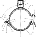
- Figures 1 to 3 show an example of a pipe clamp.
- the pipe clamp comprises a first clamping part 10 and a second clamping part 20, between which a pipe (not shown) is intended to be arranged.
- the first clamping part 10 comprises a first bow 12 intended to encompass the pipe, wherein the first bow 12 has a first end, and at the opposite end of the first bow 12, a second end.
- the first clamping part 10 furthermore comprises a locking pin 11, which projects from the first bow 12 at the first end thereof.
- the first clamping part 10 furthermore comprises a first screw flange 13, which projects from the first bow 12 at the second end thereof.
- the locking pin 11, the first bow 12 and the first screw flange 13 form a monolithic part.
- the first clamping part 10 furthermore comprises a - by way of example internally threaded - rod receiver bore 19.
- the internally threaded rod receiver bore 19 is, by way of example, provided within a nut 18 which is arranged on and connected to the first bow 12.
- the rod receiver bore 19 is intended for receiving, in particular screwingly receiving, a connector rod, in particular a threaded connector rod, for connecting the pipe clamp to a building.
- the rod receiver bore 19 defines a load axis 99 of the pipe clamp - this load axis 99 of the pipe clamp is the thread axis of the internally threaded rod receiver bore 19.
- the rod receiver bore 19 might be unthreaded and/or be provided within the first bow 12.
- the locking pin 11 comprises a locking tooth 30.
- the locking tooth 30 is formed as a notch provided in the limbs of the generally U-shaped locking pin 11.
- the locking pin 11 is a toothed rack, comprising, in addition to the locking tooth 30, at least one auxiliary tooth 31 (two auxiliary teeth 31 in the present example).
- the second clamping part 20 comprises a second bow 22 intended to encompass the pipe, wherein the second bow 22 has a first end, and at the opposite end of the second bow 22, a second end.
- the second clamping part 20 further comprises a locking flange 21, which projects from the second bow 22 at the first end thereof.
- the second clamping part 20 furthermore comprises a second screw flange 23, which projects from the second bow 22 at the second end thereof.
- the locking flange 21, the second bow 22 and the second screw flange 23 form a monolithic part.
- the locking flange 21 has a pin receiver opening 24, which passes through the locking flange 21.
- the second clamping part 20 furthermore comprises a pawl flap 25, which is arranged adjacent to the locking flange 21, and which is pivotably connected to the locking flange 21 via a hinge 28.
- the pawl flap 25 is arranged on an underside of the locking flange 21 that is located adjacent to the second bow 22, and that faces away from the first bow 12. In other words, the pawl flap 25 is arranged adjacent to the second bow 22.
- the pawl flap 25 points from the hinge 28 towards the second bow 22. Thus, the pawl flap 25 extends between the second bow 22 and the hinge 28.
- the second clamping part 20 further comprises a spring 29 that urges the pawl flap 25 into a closed position, i.e. into a position adjoining the locking flange 21.
- the spring 29 is an elastic band that encompasses the locking flange 21 and the pawl flap 25.
- the hinge 28 comprises, by way of example, a hinge tab provided on the pawl flap 25, which hinge flap passes through a hinge opening within the locking flange 21, and a L-structure provided at the end of the locking flange 21.
- the pawl flap 25 provides a catch for catching the locking tooth 30.
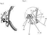
- the pawl flap 25 pivots into an open position (as schematically shown in figure 3 ), and is then, by means of the spring 29, forced back into a closed position, in which the pawl flap 25 is generally parallel with respect to the locking flange 21, in which it partly obstructs the pin receiver opening 24 and engages the locking tooth 30 or the auxiliary tooth 31, respectively.
- Figures 1 and 2 show the pipe clamp in a closed state. In this state, the pawl flap 25 engages into the locking tooth 30. This provides a first connection between the first clamping part 10 and the second clamping part 20 (or a first connection between the first bow 12 and the second bow 22, respectively).
- a headed tightening screw 91 passes through the through bore that is provided within the first screw flange 13 into the internally threaded through bore that is provided in the second screw flange 23, thereby providing a second connection between the first clamping part 10 and the second clamping part 20 (or a second connection between the first bow 12 and the second bow 22, respectively).
- the locking flange 21 of the second clamping part 20 lies on a flange plane 98.
- the flange plane 98 intersects the load axis 99, thereby defining a flange-load intersection angle ⁇ , which opens towards the connector rod receiver bore 19 (and towards the first bow 12).
- This flange-load intersection angle ⁇ is an acute angle of about 55°.
- Figure 2 schematically illustrates the load distribution resulting from this acute-angled arrangement.
- the closure force F divides into normal force Fn and axial force Fa (directed parallel to the locking flange 21), and normal force Fn is thus reduced as compared to a conventional setup where the flange-load intersection angle ⁇ is 90°. Accordingly, load capacity can be increased. In addition, improved self-locking can be achieved.
- the acute orientation of the pawl flap 25 can results in a smaller rotation requirement of the pawl flap 25 when the locking pin 11 is inserted into the pin receiver opening 24.
Landscapes
- Engineering & Computer Science (AREA)
- General Engineering & Computer Science (AREA)
- Mechanical Engineering (AREA)
- Clamps And Clips (AREA)
- Supports For Pipes And Cables (AREA)
Claims (5)
- Rohrschelle, umfassend- ein erstes Klemmteil (10), wobei das erste Klemmteil (10) einen ersten Bogen (12) mit einem ersten Ende und einem gegenüberliegenden zweiten Ende umfasst, wobei das erste Klemmteil (10) ferner eine Verbindungsstabaufnahmebohrung (19) umfasst, die an dem ersten Bogen (12) bereitgestellt ist, um einen Verbindungsstab so aufzunehmen, dass die Rohrschelle mit dem Verbindungsstab verbunden wird, wobei die Verbindungsstabaufnahmebohrung (19) eine Lastachse (99) der Rohrschelle definiert, und wobei das erste Klemmteil (10) ferner einen Verriegelungsstift (11) mit einem Verriegelungszahn (30) umfasst, wobei der Verriegelungsstift (11) an dem ersten Ende des ersten Bogens (12) aus dem ersten Bogen (12) hervorsteht, und- ein zweites Klemmteil (20), wobei das zweite Klemmteil (20) einen zweiten Bogen (22) mit einem ersten Ende und einem gegenüberliegenden zweiten Ende umfasst, wobei das zweite Klemmteil (20) ferner einen Verriegelungsflansch (21) umfasst, der an dem ersten Ende des zweiten Bogens (22) mit dem zweiten Bogen (22) verbunden ist, wobei in dem Verriegelungsflansch (21) eine Stiftaufnahmeöffnung (24) zum Aufnehmen des Verriegelungsstifts (11) bereitgestellt ist, wobei das zweite Klemmteil (20) ferner eine Sperrklinkenklappe (25) und ein Scharnier (28) umfasst, das die Sperrklinkenklappe (25) schwenkbar mit dem Verriegelungsflansch (21) verbindet, wobei die Sperrklinkenklappe (25) aus dem Scharnier (28) in Richtung des zweiten Bogens (22) hervorsteht, und wobei die Sperrklinkenklappe (25) das Einführen des Verriegelungsstifts (11) in die Stiftaufnahmeöffnung (24) ermöglicht und das Herausziehen des Verriegelungsstifts (11) aus der Stiftaufnahmeöffnung (24) verhindert, indem sie den Verriegelungszahn (30) des Verriegelungsstifts (11) auffängt,- wobei der erste Bogen (12) und der zweite Bogen (22) an ihren jeweiligen zweiten Enden miteinander verbunden sind,- wobei der Verriegelungsflansch (21) des zweiten Klemmteils (20) auf einer Flanschebene (98) liegt, und- wobei, wenn der Verriegelungsstift (11) in der Stiftaufnahmeöffnung (24) angeordnet ist und die Sperrklinkenklappe (25) in den Verriegelungszahn (30) eingreift, die Flanschebene (98) die Lastachse (99) schneidet und dadurch einen Flansch-Last-Schnittwinkel (α) definiert, der sich in Richtung der Verbindungsstabaufnahmebohrung (19) öffnet,
dadurch gekennzeichnet, dass- der Flansch-Last-Schnittwinkel (α) ein spitzer Winkel ist, der zwischen 35° und 75° beträgt. - Rohrschelle nach Anspruch 1,
dadurch gekennzeichnet, dass
der Flansch-Last-Schnittwinkel (a) 55° ± 5° beträgt. - Rohrschelle nach einem der vorstehenden Ansprüche,
dadurch gekennzeichnet, dass
der Verriegelungsstift (11) eine Zahnstange ist, die zusätzlich zum Verriegelungszahn (30) mindestens einen Hilfszahn (31) umfasst. - Rohrschelle nach einem der vorstehenden Ansprüche,
dadurch gekennzeichnet, dass
die Verbindungsstabaufnahmebohrung (19) mit einem Innengewinde zum Verbinden der Rohrschelle mit einem mit Gewinde versehenen Verbindungsstab versehen ist. - Rohrschelle nach einem der vorstehenden Ansprüche,
dadurch gekennzeichnet, dassdas erste Klemmteil (10) einen ersten Schraubflansch (13) umfasst, der am zweiten Ende des ersten Bogens (12) damit verbunden ist,das zweite Klemmteil (20) einen zweiten Schraubflansch (23) umfasst, der am zweiten Ende des zweiten Bogens (22) mit dem zweiten Bogen (22) verbunden ist, undder erste Bügel (12) und der zweite Bügel (22) an ihren jeweiligen zweiten Enden mittels einer Spannschraube (91), die durch den ersten Schraubflansch (13) und durch den zweiten Schraubflansch (23) verläuft, miteinander verbunden sind.
Applications Claiming Priority (2)
| Application Number | Priority Date | Filing Date | Title |
|---|---|---|---|
| EP20207688.1A EP4001722A1 (de) | 2020-11-16 | 2020-11-16 | Rohrschelle mit spitzwinkligem flansch |
| PCT/EP2021/080657 WO2022101085A1 (en) | 2020-11-16 | 2021-11-04 | Pipe clamp with acutely angled flange |
Publications (3)
| Publication Number | Publication Date |
|---|---|
| EP4244513A1 EP4244513A1 (de) | 2023-09-20 |
| EP4244513B1 true EP4244513B1 (de) | 2025-01-01 |
| EP4244513C0 EP4244513C0 (de) | 2025-01-01 |
Family
ID=73452009
Family Applications (2)
| Application Number | Title | Priority Date | Filing Date |
|---|---|---|---|
| EP20207688.1A Withdrawn EP4001722A1 (de) | 2020-11-16 | 2020-11-16 | Rohrschelle mit spitzwinkligem flansch |
| EP21802734.0A Active EP4244513B1 (de) | 2020-11-16 | 2021-11-04 | Rohrschelle mit spitzwinkligem flansch |
Family Applications Before (1)
| Application Number | Title | Priority Date | Filing Date |
|---|---|---|---|
| EP20207688.1A Withdrawn EP4001722A1 (de) | 2020-11-16 | 2020-11-16 | Rohrschelle mit spitzwinkligem flansch |
Country Status (2)
| Country | Link |
|---|---|
| EP (2) | EP4001722A1 (de) |
| WO (1) | WO2022101085A1 (de) |
Families Citing this family (1)
| Publication number | Priority date | Publication date | Assignee | Title |
|---|---|---|---|---|
| EP4474688A1 (de) | 2023-06-08 | 2024-12-11 | Illinois Tool Works Inc. | Klemmring zur befestigung von rohren |
Citations (1)
| Publication number | Priority date | Publication date | Assignee | Title |
|---|---|---|---|---|
| EP0597805B1 (de) * | 1992-11-07 | 1996-04-24 | HILTI Aktiengesellschaft | Rohrschelle |
Family Cites Families (1)
| Publication number | Priority date | Publication date | Assignee | Title |
|---|---|---|---|---|
| DE102015112936A1 (de) * | 2015-08-06 | 2017-02-09 | Fischerwerke Gmbh & Co. Kg | Rohrschelle |
-
2020
- 2020-11-16 EP EP20207688.1A patent/EP4001722A1/de not_active Withdrawn
-
2021
- 2021-11-04 EP EP21802734.0A patent/EP4244513B1/de active Active
- 2021-11-04 WO PCT/EP2021/080657 patent/WO2022101085A1/en not_active Ceased
Patent Citations (1)
| Publication number | Priority date | Publication date | Assignee | Title |
|---|---|---|---|---|
| EP0597805B1 (de) * | 1992-11-07 | 1996-04-24 | HILTI Aktiengesellschaft | Rohrschelle |
Also Published As
| Publication number | Publication date |
|---|---|
| EP4244513A1 (de) | 2023-09-20 |
| EP4001722A1 (de) | 2022-05-25 |
| WO2022101085A1 (en) | 2022-05-19 |
| EP4244513C0 (de) | 2025-01-01 |
Similar Documents
| Publication | Publication Date | Title |
|---|---|---|
| US6443403B1 (en) | Cable routing clamp and method of application | |
| US7441311B2 (en) | T-bolt clamp quick attach latch | |
| US20160003288A1 (en) | Tapered Flange Nut With Locking Insert | |
| US20080005876A1 (en) | Snap lock carabiner | |
| US20090026766A1 (en) | Pipe clip | |
| EP2241766A1 (de) | Rohrschelle | |
| US4563119A (en) | Hook cutout for tangless helically coiled insert | |
| US9791061B2 (en) | Valve | |
| US8439616B2 (en) | Locking threaded fastener | |
| US6971925B1 (en) | Rotatable connector for a battery cable clamp | |
| EP4001722A1 (de) | Rohrschelle mit spitzwinkligem flansch | |
| US20200248737A1 (en) | Positive locking fastener | |
| EP0419555A1 (de) | Nietloser mutternhalter und befestigungselement. | |
| JP2023171411A (ja) | ルーフマウントアンテナ取付構造 | |
| US7338241B2 (en) | Fastener receptacle | |
| US20080080928A1 (en) | Universal end fitting and fastener assembly comprising such an end fitting | |
| US20040141828A1 (en) | Device for mounting a component such as a pipe on a stud | |
| US12151603B1 (en) | Load binder apparatus | |
| KR20100009746A (ko) | 풀림방지용 너트캡 | |
| US10495133B2 (en) | Captive bolt and retainer | |
| CA1212223A (en) | Locking fastener | |
| US6726419B2 (en) | Retention pin redundancy system | |
| JPH028498A (ja) | コンクリート部材の締結装置 | |
| CZ372499A3 (cs) | Trubní objímka | |
| US5050275A (en) | Hose clamp |
Legal Events
| Date | Code | Title | Description |
|---|---|---|---|
| STAA | Information on the status of an ep patent application or granted ep patent |
Free format text: STATUS: UNKNOWN |
|
| STAA | Information on the status of an ep patent application or granted ep patent |
Free format text: STATUS: THE INTERNATIONAL PUBLICATION HAS BEEN MADE |
|
| PUAI | Public reference made under article 153(3) epc to a published international application that has entered the european phase |
Free format text: ORIGINAL CODE: 0009012 |
|
| STAA | Information on the status of an ep patent application or granted ep patent |
Free format text: STATUS: REQUEST FOR EXAMINATION WAS MADE |
|
| 17P | Request for examination filed |
Effective date: 20230616 |
|
| AK | Designated contracting states |
Kind code of ref document: A1 Designated state(s): AL AT BE BG CH CY CZ DE DK EE ES FI FR GB GR HR HU IE IS IT LI LT LU LV MC MK MT NL NO PL PT RO RS SE SI SK SM TR |
|
| DAV | Request for validation of the european patent (deleted) | ||
| DAX | Request for extension of the european patent (deleted) | ||
| GRAP | Despatch of communication of intention to grant a patent |
Free format text: ORIGINAL CODE: EPIDOSNIGR1 |
|
| STAA | Information on the status of an ep patent application or granted ep patent |
Free format text: STATUS: GRANT OF PATENT IS INTENDED |
|
| GRAS | Grant fee paid |
Free format text: ORIGINAL CODE: EPIDOSNIGR3 |
|
| INTG | Intention to grant announced |
Effective date: 20240919 |
|
| GRAA | (expected) grant |
Free format text: ORIGINAL CODE: 0009210 |
|
| STAA | Information on the status of an ep patent application or granted ep patent |
Free format text: STATUS: THE PATENT HAS BEEN GRANTED |
|
| AK | Designated contracting states |
Kind code of ref document: B1 Designated state(s): AL AT BE BG CH CY CZ DE DK EE ES FI FR GB GR HR HU IE IS IT LI LT LU LV MC MK MT NL NO PL PT RO RS SE SI SK SM TR |
|
| REG | Reference to a national code |
Ref country code: GB Ref legal event code: FG4D |
|
| REG | Reference to a national code |
Ref country code: CH Ref legal event code: EP |
|
| REG | Reference to a national code |
Ref country code: DE Ref legal event code: R096 Ref document number: 602021024348 Country of ref document: DE |
|
| REG | Reference to a national code |
Ref country code: IE Ref legal event code: FG4D |
|
| U01 | Request for unitary effect filed |
Effective date: 20250117 |
|
| U07 | Unitary effect registered |
Designated state(s): AT BE BG DE DK EE FI FR IT LT LU LV MT NL PT RO SE SI Effective date: 20250123 |
|
| PG25 | Lapsed in a contracting state [announced via postgrant information from national office to epo] |
Ref country code: PL Free format text: LAPSE BECAUSE OF FAILURE TO SUBMIT A TRANSLATION OF THE DESCRIPTION OR TO PAY THE FEE WITHIN THE PRESCRIBED TIME-LIMIT Effective date: 20250101 |
|
| PG25 | Lapsed in a contracting state [announced via postgrant information from national office to epo] |
Ref country code: ES Free format text: LAPSE BECAUSE OF FAILURE TO SUBMIT A TRANSLATION OF THE DESCRIPTION OR TO PAY THE FEE WITHIN THE PRESCRIBED TIME-LIMIT Effective date: 20250101 |
|
| PG25 | Lapsed in a contracting state [announced via postgrant information from national office to epo] |
Ref country code: NO Free format text: LAPSE BECAUSE OF FAILURE TO SUBMIT A TRANSLATION OF THE DESCRIPTION OR TO PAY THE FEE WITHIN THE PRESCRIBED TIME-LIMIT Effective date: 20250401 Ref country code: IS Free format text: LAPSE BECAUSE OF FAILURE TO SUBMIT A TRANSLATION OF THE DESCRIPTION OR TO PAY THE FEE WITHIN THE PRESCRIBED TIME-LIMIT Effective date: 20250501 |
|
| PG25 | Lapsed in a contracting state [announced via postgrant information from national office to epo] |
Ref country code: HR Free format text: LAPSE BECAUSE OF FAILURE TO SUBMIT A TRANSLATION OF THE DESCRIPTION OR TO PAY THE FEE WITHIN THE PRESCRIBED TIME-LIMIT Effective date: 20250101 |
|
| PG25 | Lapsed in a contracting state [announced via postgrant information from national office to epo] |
Ref country code: GR Free format text: LAPSE BECAUSE OF FAILURE TO SUBMIT A TRANSLATION OF THE DESCRIPTION OR TO PAY THE FEE WITHIN THE PRESCRIBED TIME-LIMIT Effective date: 20250402 |
|
| PG25 | Lapsed in a contracting state [announced via postgrant information from national office to epo] |
Ref country code: CZ Free format text: LAPSE BECAUSE OF FAILURE TO SUBMIT A TRANSLATION OF THE DESCRIPTION OR TO PAY THE FEE WITHIN THE PRESCRIBED TIME-LIMIT Effective date: 20250101 |
|
| PG25 | Lapsed in a contracting state [announced via postgrant information from national office to epo] |
Ref country code: SM Free format text: LAPSE BECAUSE OF FAILURE TO SUBMIT A TRANSLATION OF THE DESCRIPTION OR TO PAY THE FEE WITHIN THE PRESCRIBED TIME-LIMIT Effective date: 20250101 |
|
| PG25 | Lapsed in a contracting state [announced via postgrant information from national office to epo] |
Ref country code: SK Free format text: LAPSE BECAUSE OF FAILURE TO SUBMIT A TRANSLATION OF THE DESCRIPTION OR TO PAY THE FEE WITHIN THE PRESCRIBED TIME-LIMIT Effective date: 20250101 |
|
| PLBE | No opposition filed within time limit |
Free format text: ORIGINAL CODE: 0009261 |
|
| STAA | Information on the status of an ep patent application or granted ep patent |
Free format text: STATUS: NO OPPOSITION FILED WITHIN TIME LIMIT |
|
| REG | Reference to a national code |
Ref country code: CH Ref legal event code: L10 Free format text: ST27 STATUS EVENT CODE: U-0-0-L10-L00 (AS PROVIDED BY THE NATIONAL OFFICE) Effective date: 20251112 |
|
| REG | Reference to a national code |
Ref country code: CH Ref legal event code: U11 Free format text: ST27 STATUS EVENT CODE: U-0-0-U10-U11 (AS PROVIDED BY THE NATIONAL OFFICE) Effective date: 20251201 |
|
| 26N | No opposition filed |
Effective date: 20251002 |
|
| U20 | Renewal fee for the european patent with unitary effect paid |
Year of fee payment: 5 Effective date: 20251127 |
|
| PGFP | Annual fee paid to national office [announced via postgrant information from national office to epo] |
Ref country code: GB Payment date: 20251121 Year of fee payment: 5 |
|
| PGFP | Annual fee paid to national office [announced via postgrant information from national office to epo] |
Ref country code: CH Payment date: 20251201 Year of fee payment: 5 |
|
| PG25 | Lapsed in a contracting state [announced via postgrant information from national office to epo] |
Ref country code: MC Free format text: LAPSE BECAUSE OF FAILURE TO SUBMIT A TRANSLATION OF THE DESCRIPTION OR TO PAY THE FEE WITHIN THE PRESCRIBED TIME-LIMIT Effective date: 20250101 |
|
| PG25 | Lapsed in a contracting state [announced via postgrant information from national office to epo] |
Ref country code: RS Free format text: LAPSE BECAUSE OF FAILURE TO SUBMIT A TRANSLATION OF THE DESCRIPTION OR TO PAY THE FEE WITHIN THE PRESCRIBED TIME-LIMIT Effective date: 20250101 |