EP4244430B1 - Snow removal device with continuously rotatable discharge chute - Google Patents
Snow removal device with continuously rotatable discharge chute Download PDFInfo
- Publication number
- EP4244430B1 EP4244430B1 EP21802461.0A EP21802461A EP4244430B1 EP 4244430 B1 EP4244430 B1 EP 4244430B1 EP 21802461 A EP21802461 A EP 21802461A EP 4244430 B1 EP4244430 B1 EP 4244430B1
- Authority
- EP
- European Patent Office
- Prior art keywords
- chute
- deflector
- assembly
- motor
- removal device
- Prior art date
- Legal status (The legal status is an assumption and is not a legal conclusion. Google has not performed a legal analysis and makes no representation as to the accuracy of the status listed.)
- Active
Links
Images


Classifications
-
- E—FIXED CONSTRUCTIONS
- E01—CONSTRUCTION OF ROADS, RAILWAYS, OR BRIDGES
- E01H—STREET CLEANING; CLEANING OF PERMANENT WAYS; CLEANING BEACHES; DISPERSING OR PREVENTING FOG IN GENERAL CLEANING STREET OR RAILWAY FURNITURE OR TUNNEL WALLS
- E01H5/00—Removing snow or ice from roads or like surfaces; Grading or roughening snow or ice
- E01H5/04—Apparatus propelled by animal or engine power; Apparatus propelled by hand with driven dislodging or conveying levelling elements, conveying pneumatically for the dislodged material
- E01H5/08—Apparatus propelled by animal or engine power; Apparatus propelled by hand with driven dislodging or conveying levelling elements, conveying pneumatically for the dislodged material dislodging essentially by driven elements
- E01H5/09—Apparatus propelled by animal or engine power; Apparatus propelled by hand with driven dislodging or conveying levelling elements, conveying pneumatically for the dislodged material dislodging essentially by driven elements the elements being rotary or moving along a closed circular path, e.g. rotary cutter, digging wheels
- E01H5/098—Apparatus propelled by animal or engine power; Apparatus propelled by hand with driven dislodging or conveying levelling elements, conveying pneumatically for the dislodged material dislodging essentially by driven elements the elements being rotary or moving along a closed circular path, e.g. rotary cutter, digging wheels about horizontal or substantially horizontal axises perpendicular or substantially perpendicular to the direction of clearing
-
- E—FIXED CONSTRUCTIONS
- E01—CONSTRUCTION OF ROADS, RAILWAYS, OR BRIDGES
- E01H—STREET CLEANING; CLEANING OF PERMANENT WAYS; CLEANING BEACHES; DISPERSING OR PREVENTING FOG IN GENERAL CLEANING STREET OR RAILWAY FURNITURE OR TUNNEL WALLS
- E01H5/00—Removing snow or ice from roads or like surfaces; Grading or roughening snow or ice
- E01H5/04—Apparatus propelled by animal or engine power; Apparatus propelled by hand with driven dislodging or conveying levelling elements, conveying pneumatically for the dislodged material
- E01H5/045—Means per se for conveying or discharging the dislodged material, e.g. rotary impellers, discharge chutes
-
- E—FIXED CONSTRUCTIONS
- E01—CONSTRUCTION OF ROADS, RAILWAYS, OR BRIDGES
- E01H—STREET CLEANING; CLEANING OF PERMANENT WAYS; CLEANING BEACHES; DISPERSING OR PREVENTING FOG IN GENERAL CLEANING STREET OR RAILWAY FURNITURE OR TUNNEL WALLS
- E01H5/00—Removing snow or ice from roads or like surfaces; Grading or roughening snow or ice
- E01H5/04—Apparatus propelled by animal or engine power; Apparatus propelled by hand with driven dislodging or conveying levelling elements, conveying pneumatically for the dislodged material
- E01H5/08—Apparatus propelled by animal or engine power; Apparatus propelled by hand with driven dislodging or conveying levelling elements, conveying pneumatically for the dislodged material dislodging essentially by driven elements
Definitions
- Example embodiments generally relate to snow removal devices and, more particularly, relate to a snow removal device (e.g., a robotic vehicle) that has a discharge chute capable of rotating 360 degrees.
- a snow removal device e.g., a robotic vehicle
- a discharge chute capable of rotating 360 degrees.
- Grounds maintenance tasks are commonly performed using various tools and/or machines that are configured for the performance of corresponding specific tasks. Certain tasks, like snow or ice removal, are typically performed using manually operated tools or vehicles. More recently, robotic devices and/or remote controlled devices have also become options for consumers to consider. Moreover, the use of a robotic vehicle that operates either autonomously or via remote control may create a number of unique design and operational considerations that are normally not possible for manually operated devices.
- WO 2019/038695 A1 discloses a manual snow removal device, which may include an engine assembly operably coupled at least in part to a frame of the snow removal device.
- the snow removal device may further include a mobility assembly operably coupled to the frame and the engine assembly to provide mobility of the snow removal device responsive at least in part to operation of the engine assembly, an ejection assembly that includes a chute for ejecting material from the snow removal device, and a handle assembly that includes a lever assembly.
- the snow removal device may also include a chute rotation assembly operably coupled to the chute of the ejection assembly.
- the chute rotation assembly may include a cable system, the cable system operably coupling the lever assembly to the chute rotation assembly.
- the chute rotation assembly may also include a disc clutch assembly configured to move between an engaged position and a disengaged position in response to actuation of the lever assembly, where when the disc clutch assembly is in the disengaged position, the chute is enabled to rotate between a plurality of positions.
- US 2019/048544 A1 describes a chute control assembly for a snow thrower having a housing, handle, and a chute, which includes a control mechanism, a connecting mechanism, and a guide mechanism.
- the control mechanism may include an actuator mechanism that allows an operator to manually control the orientation of the chute from a position spaced apart from the chute.
- the connecting mechanism may transfer the rotation of the actuator mechanism to the guide mechanism, which is attached to the chute and rotates and adjust the orientation of the chute in response to rotation of the actuator mechanism in order to change the direction that snow is thrown from the snow thrower.
- WO 2013/173338 A1 shows a snow thrower which comprises an auger housing, a chute extending from the auger housing, a first snow engaging blade rotatably supported within the auger housing opposite the chute and a second snow engaging blade rotatably supported within the auger housing on a first side of the first snow engaging blade.
- the first snow engaging blade and the second snow engaging blade may be rotatable at different speeds relative to one another.
- the snow removal device may include a chassis supporting a power unit, a mobility assembly operably coupled to the chassis to provide mobility for the snow removal device responsive to power provision from the power unit, a working assembly configured to move snow to an ejection path responsive to power provision from the power unit, and a chute assembly forming a portion of the ejection path, the chute assembly comprising a chute and a deflector.
- the chute may be rotatable via a chute rotator configured to provide at least 360 degree automated rotation of the chute.
- An orientation of the deflector may be changeable via automated pivoting of the deflector via an electrically operable deflector adjuster.
- the chute rotator may comprise a contact plate assembly configured to rotate with the chute and interface with a brush assembly to provide power from the power unit to the deflector adjuster.
- a chute assembly for a snow removal device may be provided.
- the chute assembly may include a chute forming a portion of an ejection path from a working assembly of the snow removal device, and a deflector disposed at a distal end of the chute.
- the chute may be rotatable via a chute rotator configured to provide at least 360 degree automated rotation of the chute responsive to power provision from a power unit.
- An orientation of the deflector is changeable via automated pivoting of the deflector via an electrically operable deflector adjuster.
- the chute rotator may comprise a contact plate assembly configured to rotate with the chute and interface with a brush assembly to provide power from the power unit to the deflector adjuster.
- robotic snow removal machines may enable new design options that had not previously been needed or considered helpful.
- the location at which the operator engages with the machine e.g., the operator station
- the location at which the operator engages with the machine is essentially disqualified as a possible direction to which the discharge chute may be selected for discharging snow being ejected from the machine.
- the operator station is eliminated, and the possibility of having a snow removal device that can eject snow to any selectable direction, 360 degrees around the device becomes possible.
- Some of the design features of conventional snow removal devices for providing rotation of the discharge chute, and for controlling a deflector (e.g., at the distal end of the chute) involve cables or wires, and are therefore incompatible with a chute that can rotate continuously over a 360 degree range. In this regard, the wires or cables would become wrapped around components at some point and limit movement, or even be damaged.
- Some example embodiments may provide a snow removal device (e.g., a remotely controllable or autonomous robotic vehicle) that employs a rotator (or rotation assembly) that is capable of continuously rotating over more than 360 degrees.
- a rotator or rotation assembly
- Example embodiments may provide such a rotator that also has a deflector that is operable to change position without manual interaction by the operator and instead under electrically operable controls.
- FIG. 1 illustrates an example of a remotely operable or autonomously operable robotic vehicle in the form of a snow removal device 10
- FIG. 2 illustrates a block diagram of the snow removal device 10.
- the snow removal device 10 e.g., a snow blower or snow thrower
- FIGS. 1 and 2 illustrate a block diagram of the snow removal device 10.
- the snow removal device 10 e.g., a snow blower or snow thrower
- FIGS. 1 and 2 illustrates a block diagram of the snow removal device 10.
- the snow removal device 10 e.g., a snow blower or snow thrower
- example embodiments could be employed in connection with other devices that are not robotic as well.
- walk behind power equipment may use example embodiments as well.
- the operator station is movable, or the device may convert between manual and remote/autonomous operation. But in any case, it should be appreciated that example embodiments can be implemented on any snow removal device and not just on robotic vehicles.
- the snow removal device 10 may include a chassis 15 or frame to which various components of the snow removal device 10 may be attached.
- the chassis 15 may support a power unit housing 20 inside which a power unit 22 such as an engine (e.g., a gasoline powered engine) or an electric motor and corresponding battery may be housed.
- the power unit 22 may be operably coupled to a mobility assembly 30 (which is a track assembly 32 in this example) and a working assembly 40 to power either or both of the mobility assembly 30 and the working assembly 40.
- the snow removal device 10 may include a track assembly 32 (or continuous tracks), wheels or any other suitable means for moving the snow removal device 10 as the mobility assembly 30.
- the mobility assembly 30 may support a substantial portion of the weight of the snow removal device 10 when the snow removal device 10 is stationary.
- the mobility assembly 30 may also provide for mobility of the snow removal device 10. In some cases, the mobility assembly 30 may be driven via power from the power unit 22 based on remote or autonomous control inputs.
- the working assembly 40 may be a single or dual stage snow thrower.
- the working assembly 40 may include a rotatable auger (or auger blade) that is configured to work (e.g., spin, rotate, turn, and/or the like) in order to direct snow toward an impeller (or impeller blade) that also works (e.g., spins, rotates, turns, and/or the like) to direct snow toward a discharge path to be ejected from the snow removal device 10.
- a rotatable auger or auger blade
- the working assembly 40 may include a rotatable auger (or auger blade) that is configured to work (e.g., spin, rotate, turn, and/or the like) in order to direct snow toward an impeller (or impeller blade) that also works (e.g., spins, rotates, turns, and/or the like) to direct snow toward a discharge path to be ejected from the snow removal device 10.
- Single stage versions may only include only the auger.
- the working assembly 40 of some embodiments could include a power brush or other implement used to move snow toward a second stage device (e.g., the impeller) for ejection from the working assembly 40.
- the working assembly 40 may be powered via operable coupling to the power unit 22.
- the operable coupling of the working assembly 40 to the power unit 22 may be selectively engaged and/or disengaged (e.g., via a clutch, one or more selectively engageable chains/belts/pulleys, a friction wheel or other similar devices).
- Components of the working assembly 40 e.g., the auger and the impeller
- the bucket assembly 32 prevents escape of snow and directs the snow into the ejection path.
- the bucket assembly 32 also protects the operator from blowback and allows for a somewhat orderly disposal of the snow that is ejected by the snow removal device 10.
- the ejection path of the snow removal device 10 may be formed at least in part by the bucket assembly 32 and a discharge chute or chute assembly 50.
- the ejection path may begin proximate to an input of the impeller, at which point snow is imparted with momentum at an output of the impeller to be pushed toward, and ultimately through, the chute assembly 50.
- the chassis 15 may also support the chute assembly 50.
- the chute assembly 50 may include a chute 52 and a deflector 54.
- the chute 52 may define an ejection path for snow propelled by or from the working assembly 40.
- the chute 52 may, in some cases, be an elongated sheet (or sheets) of metal or other rigid material that may be formed to partially or fully enclose the lateral sides of the ejection path. In the example shown, the chute 52 encloses only three sides of the ejection path in order to minimize the material required to form the chute 52. However, all four sides may be enclosed in some alternatives.
- the deflector 54 may be disposed at a distal end of the chute 52 to provide an adjustable deflection surface for direction snow ejected from the distal end of the chute 52 at a desired angle relative to the direction of travel of the snow in the chute 52.
- the deflector 54 may be a sheet (or sheets) of metal or other rigid material that can be rotated relative to the distal end of the chute 52 in order to change the deflection angle for ejected snow.
- the chute 52 and the deflector 54 may be adjustable.
- the chute 52 may therefore be adjustable to another chute orientation 52', and the deflector 54 may also be adjustable to other deflector orientations 54' and 54". While these adjustments of orientation are known in general terms, they are typically conducted in a context in which there are physical limits to the adjustability of the chute 52 (e.g., over a range of angles). The physical limits tend to facilitate (or allow) use of cables and wires for pulling and turning components for adjustment of the chute 52 and/or deflector 54.
- example embodiments may allow the adjustment of the chute 52 to the other chute orientation 52' to pass through a continuous range of 360 degrees.
- the chute 52 could be directly adjusted from the position shown in FIG. 1 to the other chute orientation 52' in either direction.
- any number of full circles of 360 degrees could be conducted prior to reaching the other chute orientation 52'.
- This continuous adjustment capability for the chute 52 not only renders the use of cables and wires impossible for the adjustment of the chute 52, but remote adjustment of the deflector 54 is also disrupted by this significant modification.
- the chute assembly 50 of example embodiments may also include a chute rotator 56 and a deflector adjuster 58 as described in greater detail below.
- the chute rotator 56 may be configured to enable continuous adjustment of the chute 52 over greater than 360 degrees
- the defector adjuster 58 may allow remote adjustment of the deflector 54 in the context of a fully rotatable (i.e., greater than 360 degrees) chute 52.
- FIG. 2 illustrates various structures of the chute rotator 56 and the deflector adjuster 58 of an example embodiment.
- the chute rotator 56 may include a gear assembly 70 and a chute motor 72 (e.g., an electric motor such as a brushless DC (BLDC) motor).
- the gear assembly 70 may include a drive gear that receives power from the chute motor 72 and a driven gear that is affixed to the chute 52 so that when the driven gear turns, the chute 52 turns with the driven gear.
- BLDC brushless DC
- the chute motor 72 may receive power from the power unit 22 (e.g., responsive to receipt of a rotation instruction from a local controller or remote controller of the snow removal device 10) and may turn the drive gear according to the rotation instruction received (e.g., in the direction and perhaps also at the speed instructed).
- the drive gear may correspondingly engage the driven gear and turn the driven gear accordingly.
- the chute 52 may then be carried with the driven gear to rotate in accordance with the rotation instruction.
- Some embodiments may further include one or more instances of an idler gear between the drive gear and the driven gear.
- the chute rotator 56 may solve this problem by providing a contact plate assembly 80 that is configured to provide power to the deflector adjuster 58 even when the chute rotator 56 enables full continuous 360 degree rotation of the chute 52.
- the contact plate assembly 80 may include substantially circular electrically conductive plates that have a central opening that corresponds to the ejection path defined through the chute 52.
- the plates of the contact plate assembly 80 may rotate with the chute 52 and the driven gear, and provide consistent power connections to a deflector motor 90 (e.g., another electric motor such as a Brushed DC motor) of the deflector adjuster 58.
- the deflector adjuster 58 may therefore receive an adjustment instruction, which may provide power to the deflector motor 90 via the contact plate assembly 80.
- the deflector motor 90 may in turn operate to drive a linear actuator 92, which may extend between the deflector 54 and the chute 52.
- the driving of the linear actuator 92 may change the orientation angle of the deflector 54 relative to the distal end of the chute 52.
- the deflector motor 90 may pull a cable or wire that is attached to the deflector 54 (e.g., via a pulley) to change the orientation of the deflector 54.
- the linear actuator 92 may be a threaded lead screw, a device capable of pulling the cable linearly in one direction or the other to actuate the deflector, or any other device that creates motion in a straight line.
- controls for operation of the working assembly 40, the mobility assembly 30, the power unit 22, and/or the chute assembly 50 may be handled by control circuitry 24 of the snow removal device 10.
- the rotation instruction for rotating the chute 52 and/or the adjustment instruction or pivoting the deflector 54 may be provided by control circuitry 24.
- the control circuitry 24 may be configurable for autonomous operation of the snow removal device 10, or the control circuitry 24 may include or otherwise be in communication with wireless communication equipment that enable remote operation of the snow removal device 10.
- the contact plate assembly 80 (and therefore the chute rotator 56) provide power for remote operation of the deflector 54 even though the chute 52 is allowed to continuously rotate over 360 degrees.
- FIGS. 3 and 4 each illustrate a partially isolated perspective view of the components of the chute rotator 56 of an example embodiment.
- FIGS. 3 and 4 show the chute motor 72, which is operably coupled to drive gear 100.
- Drive gear 100 is in turn operably coupled to driven gear 110.
- the driven gear 110 is concentrically formed along with a first plate 120 and a second plate 122 of the contact plate assembly 80.
- the driven gear 110 is, like the first and second plates 120 and 122, hollow in its center to define part of ejection path 112, which extends into the chute 52.
- the first plate 120 and the second plate 122 may, for example, be positive and negative plates, respectively (or vice versa) that are separated by an insulator 124.
- Other insulators 126 may also be provided on opposing axial sides of the first and second plates 120 and 122 to further isolate the first and second plates 120 and 122 electrically.
- a third metallic plate 128 may be provided for additional structural robustness, and the chute 52 may be operably coupled to the third metallic plate 128.
- Pins 129 may pass through the driven gear 110, the first and second plates 120 and 122, the insulators 124 and 126 and the third metallic plate 128 to keep all such components affixed relative to each other such that the rotation of the driven gear 110 (responsive to operation of the chute motor 72) causes corresponding rotation of the chute 52.
- the first plate 120 may be operably coupled to a first brush 130 and the second plate 122 may be operably coupled to a second brush 132.
- the first and second brushes 130 and 132 may form a brush assembly that provides electrical power from the power unit 22 through the contact plate assembly 80 to the deflector motor 90.
- a first conductive roll pin 140 may extend from the first plate 120 through the third metallic plate 128 and the insulators 124 and 126 that are disposed between the first plate 120 and the chute 52.
- An electrical wire, cable, or other conductor may extend from the first conductive roll pin 140 to the deflector motor 90.
- a second conductive roll pin 142 may extend from the second plate 122 through the third metallic plate 128 and the insulator 126 that is disposed between the second plate 122 and the chute 52.
- An electrical wire, cable, or other conductor may extend from the second conductive roll pin 142 to the deflector motor 90.
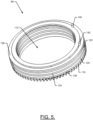
- the first and second conductive roll pins 140 and 142 which are shown in FIG. 5 , may represent positive and negative terminals for powering the deflector motor 90.
- FIG. 6 shows a distal end of the chute 52 with the deflector 54 positioned substantially aligned with walls of the chute 52 to avoid deflecting snow in the ejection path.
- the deflector 54 includes a deflector bracket 200 and a support bracket 210 is disposed proximate to the distal end of the chute 52.
- the support bracket 210 may support the deflector motor 90 of FIG. 2 , and the linear actuator 92 may operate to move the deflector bracket 200 along a line shown by arrow 220 in order to tilt the deflector 54 as shown by arrow 230.
- a robotic vehicle such as a snow removal device
- the snow removal device may include a chassis supporting a power unit, a mobility assembly operably coupled to the chassis to provide mobility for the snow removal device responsive to power provision from the power unit, a working assembly configured to move snow to an ejection path responsive to power provision from the power unit, and a chute assembly forming a portion of the ejection path, the chute assembly comprising a chute and a deflector.
- the chute may be rotatable via a chute rotator configured to provide at least 360 degree automated rotation of the chute.
- An orientation of the deflector may be changeable via automated pivoting of the deflector via an electrically operable deflector adjuster.
- the snow removal device of some embodiments may include additional features, modifications, augmentations and/or the like to achieve further objectives or enhance performance of the device.
- the additional features, modifications, augmentations and/or the like may be added in any combination with each other.
- the chute rotator may include a contact plate assembly configured to rotate with the chute and interface with a brush assembly to provide power from the power unit to the deflector adjuster.
- the deflector adjuster may include a deflector motor and a linear actuator.
- the linear actuator may be operably coupled to a deflector bracket on the deflector, and responsive to operation of the deflector motor, the linear actuator may move the deflector bracket to pivot the deflector relative to a distal end of the chute.
- the deflector motor may be disposed at a support bracket proximate to a distal end of the chute.
- the contact plate assembly may include a first conductive plate and a second conductive plate separated from each other by an insulator. The first and second conductive plates may be operably coupled to the chute to rotate with the chute.
- the first conductive plate may be operably coupled to a first conductive roll pin
- the second conductive plate may be operably coupled to a second conductive roll pin.
- the first and second conductive pins may provide positive and negative power terminals for operation of the deflector motor.
- the chute rotator may include drive gear and a driven gear.
- the drive gear may be operably coupled to a chute motor
- the driven gear may be operably coupled to the chute.
- the chute may be rotated responsive to operation of the chute motor to turn the driven gear via rotation of the drive gear.
- the driven gear, the first conductive plate and the second conductive plate may each be concentric with respect to each other and surround a portion of the ejection path.
- one or more holding members e.g., pins, screws, rivets, etc.
- the working assembly may be a single stage or dual stage snow thrower.
- the deflector adjuster may include a deflector motor
- the chute rotator may include a chute motor.
- the chute motor and the deflector motor may each be brushed DC motors.
Landscapes
- Engineering & Computer Science (AREA)
- Architecture (AREA)
- Civil Engineering (AREA)
- Structural Engineering (AREA)
- Cleaning Of Streets, Tracks, Or Beaches (AREA)
- Buildings Adapted To Withstand Abnormal External Influences (AREA)
Description
- Example embodiments generally relate to snow removal devices and, more particularly, relate to a snow removal device (e.g., a robotic vehicle) that has a discharge chute capable of rotating 360 degrees.
- Grounds maintenance tasks are commonly performed using various tools and/or machines that are configured for the performance of corresponding specific tasks. Certain tasks, like snow or ice removal, are typically performed using manually operated tools or vehicles. More recently, robotic devices and/or remote controlled devices have also become options for consumers to consider. Moreover, the use of a robotic vehicle that operates either autonomously or via remote control may create a number of unique design and operational considerations that are normally not possible for manually operated devices.
- Some of these design of operational considerations may require new solutions to be developed that had not previously been needed or considered helpful. Accordingly, it may be desirable to provide additional capabilities and corresponding devices or component assemblies that are designed to provide such additional capabilities.
-
WO 2019/038695 A1 , of the same applicant, discloses a manual snow removal device, which may include an engine assembly operably coupled at least in part to a frame of the snow removal device. The snow removal device may further include a mobility assembly operably coupled to the frame and the engine assembly to provide mobility of the snow removal device responsive at least in part to operation of the engine assembly, an ejection assembly that includes a chute for ejecting material from the snow removal device, and a handle assembly that includes a lever assembly. The snow removal device may also include a chute rotation assembly operably coupled to the chute of the ejection assembly. The chute rotation assembly may include a cable system, the cable system operably coupling the lever assembly to the chute rotation assembly. The chute rotation assembly may also include a disc clutch assembly configured to move between an engaged position and a disengaged position in response to actuation of the lever assembly, where when the disc clutch assembly is in the disengaged position, the chute is enabled to rotate between a plurality of positions. -
US 2019/048544 A1 describes a chute control assembly for a snow thrower having a housing, handle, and a chute, which includes a control mechanism, a connecting mechanism, and a guide mechanism. The control mechanism may include an actuator mechanism that allows an operator to manually control the orientation of the chute from a position spaced apart from the chute. The connecting mechanism may transfer the rotation of the actuator mechanism to the guide mechanism, which is attached to the chute and rotates and adjust the orientation of the chute in response to rotation of the actuator mechanism in order to change the direction that snow is thrown from the snow thrower. -
WO 2013/173338 A1 shows a snow thrower which comprises an auger housing, a chute extending from the auger housing, a first snow engaging blade rotatably supported within the auger housing opposite the chute and a second snow engaging blade rotatably supported within the auger housing on a first side of the first snow engaging blade. The first snow engaging blade and the second snow engaging blade may be rotatable at different speeds relative to one another. - Some example embodiments may therefore provide a snow removal device. The snow removal device may include a chassis supporting a power unit, a mobility assembly operably coupled to the chassis to provide mobility for the snow removal device responsive to power provision from the power unit, a working assembly configured to move snow to an ejection path responsive to power provision from the power unit, and a chute assembly forming a portion of the ejection path, the chute assembly comprising a chute and a deflector. The chute may be rotatable via a chute rotator configured to provide at least 360 degree automated rotation of the chute. An orientation of the deflector may be changeable via automated pivoting of the deflector via an electrically operable deflector adjuster. The chute rotator may comprise a contact plate assembly configured to rotate with the chute and interface with a brush assembly to provide power from the power unit to the deflector adjuster.
- In another example embodiment, a chute assembly for a snow removal device may be provided. The chute assembly may include a chute forming a portion of an ejection path from a working assembly of the snow removal device, and a deflector disposed at a distal end of the chute. The chute may be rotatable via a chute rotator configured to provide at least 360 degree automated rotation of the chute responsive to power provision from a power unit. An orientation of the deflector is changeable via automated pivoting of the deflector via an electrically operable deflector adjuster. The chute rotator may comprise a contact plate assembly configured to rotate with the chute and interface with a brush assembly to provide power from the power unit to the deflector adjuster.
- Having thus described the invention in general terms, reference will now be made to the accompanying drawings, which are not necessarily drawn to scale, and wherein:
-
FIG. 1 illustrates an side view of a snow removal device in accordance with an example embodiment; -
FIG. 2 illustrates a block diagram of various components of the snow removal device of an example embodiment; -
FIG. 3 illustrates a perspective view of a chute rotator in accordance with an example embodiment; -
FIG. 4 illustrates another perspective view of the chute rotator in accordance with an example embodiment; -
FIG. 5 illustrates a perspective view of a contact plate assembly of the chute rotator in isolation according to an example embodiment; and -
FIG. 6 illustrates a perspective view of a deflector according to an example embodiment. - Some example embodiments now will be described more fully hereinafter with reference to the accompanying drawings, in which some, but not all example embodiments are shown. Indeed, the examples described and pictured herein should not be construed as being limiting as to the scope, applicability or configuration of the present disclosure. Rather, these example embodiments are provided so that this disclosure will satisfy applicable legal requirements. Like reference numerals refer to like elements throughout. Furthermore, as used herein, the term "or" is to be interpreted as a logical operator that results in true whenever one or more of its operands are true. As used herein, operable coupling should be understood to relate to direct or indirect connection that, in either case, enables functional interconnection of components that are operably coupled to each other.
- As noted above, robotic snow removal machines may enable new design options that had not previously been needed or considered helpful. For example, since a manually operated snow removal machine necessarily has an operator, the location at which the operator engages with the machine (e.g., the operator station) is essentially disqualified as a possible direction to which the discharge chute may be selected for discharging snow being ejected from the machine. Thus, even though it has long been recognized that it is desirable for operators to select the direction to which the snow should be ejected from the machine, there has always been at least one direction to which ejection would simply never be desirable.
- By providing autonomous or remotely operated snow removal devices, the operator station is eliminated, and the possibility of having a snow removal device that can eject snow to any selectable direction, 360 degrees around the device becomes possible. Some of the design features of conventional snow removal devices for providing rotation of the discharge chute, and for controlling a deflector (e.g., at the distal end of the chute) involve cables or wires, and are therefore incompatible with a chute that can rotate continuously over a 360 degree range. In this regard, the wires or cables would become wrapped around components at some point and limit movement, or even be damaged.
- Some example embodiments may provide a snow removal device (e.g., a remotely controllable or autonomous robotic vehicle) that employs a rotator (or rotation assembly) that is capable of continuously rotating over more than 360 degrees. Example embodiments may provide such a rotator that also has a deflector that is operable to change position without manual interaction by the operator and instead under electrically operable controls.
-
FIG. 1 illustrates an example of a remotely operable or autonomously operable robotic vehicle in the form of asnow removal device 10, andFIG. 2 illustrates a block diagram of thesnow removal device 10. Although the snow removal device 10 (e.g., a snow blower or snow thrower) ofFIGS. 1 and2 is shown as a robotic vehicle, it should be appreciated that example embodiments could be employed in connection with other devices that are not robotic as well. Thus, for example, walk behind power equipment may use example embodiments as well. In such cases, it may be the case that the operator station is movable, or the device may convert between manual and remote/autonomous operation. But in any case, it should be appreciated that example embodiments can be implemented on any snow removal device and not just on robotic vehicles. - In some embodiments, the
snow removal device 10 may include achassis 15 or frame to which various components of thesnow removal device 10 may be attached. For example, thechassis 15 may support apower unit housing 20 inside which apower unit 22 such as an engine (e.g., a gasoline powered engine) or an electric motor and corresponding battery may be housed. Thepower unit 22 may be operably coupled to a mobility assembly 30 (which is atrack assembly 32 in this example) and aworking assembly 40 to power either or both of themobility assembly 30 and theworking assembly 40. - The
snow removal device 10 may include a track assembly 32 (or continuous tracks), wheels or any other suitable means for moving thesnow removal device 10 as themobility assembly 30. Themobility assembly 30 may support a substantial portion of the weight of thesnow removal device 10 when thesnow removal device 10 is stationary. Themobility assembly 30 may also provide for mobility of thesnow removal device 10. In some cases, themobility assembly 30 may be driven via power from thepower unit 22 based on remote or autonomous control inputs. - In an example embodiment, the working
assembly 40 may be a single or dual stage snow thrower. As such, for example, if dual stage, the workingassembly 40 may include a rotatable auger (or auger blade) that is configured to work (e.g., spin, rotate, turn, and/or the like) in order to direct snow toward an impeller (or impeller blade) that also works (e.g., spins, rotates, turns, and/or the like) to direct snow toward a discharge path to be ejected from thesnow removal device 10. Single stage versions may only include only the auger. However, it should be appreciated that the workingassembly 40 of some embodiments could include a power brush or other implement used to move snow toward a second stage device (e.g., the impeller) for ejection from the workingassembly 40. In an example embodiment, the workingassembly 40 may be powered via operable coupling to thepower unit 22. The operable coupling of the workingassembly 40 to thepower unit 22 may be selectively engaged and/or disengaged (e.g., via a clutch, one or more selectively engageable chains/belts/pulleys, a friction wheel or other similar devices). Components of the working assembly 40 (e.g., the auger and the impeller) may be housed in abucket assembly 42. - As can be appreciated from
FIG. 1 , thebucket assembly 32 prevents escape of snow and directs the snow into the ejection path. Thus, thebucket assembly 32 also protects the operator from blowback and allows for a somewhat orderly disposal of the snow that is ejected by thesnow removal device 10. The ejection path of thesnow removal device 10 may be formed at least in part by thebucket assembly 32 and a discharge chute orchute assembly 50. As such, for example, the ejection path may begin proximate to an input of the impeller, at which point snow is imparted with momentum at an output of the impeller to be pushed toward, and ultimately through, thechute assembly 50. - In an example embodiment, the
chassis 15 may also support thechute assembly 50. Thechute assembly 50 may include achute 52 and adeflector 54. Thechute 52 may define an ejection path for snow propelled by or from the workingassembly 40. Thechute 52 may, in some cases, be an elongated sheet (or sheets) of metal or other rigid material that may be formed to partially or fully enclose the lateral sides of the ejection path. In the example shown, thechute 52 encloses only three sides of the ejection path in order to minimize the material required to form thechute 52. However, all four sides may be enclosed in some alternatives. - The
deflector 54 may be disposed at a distal end of thechute 52 to provide an adjustable deflection surface for direction snow ejected from the distal end of thechute 52 at a desired angle relative to the direction of travel of the snow in thechute 52. Accordingly, for example, thedeflector 54 may be a sheet (or sheets) of metal or other rigid material that can be rotated relative to the distal end of thechute 52 in order to change the deflection angle for ejected snow. - As noted above, it is not uncommon for either or both of the
chute 52 and thedeflector 54 to be adjustable. Thechute 52 may therefore be adjustable to another chute orientation 52', and thedeflector 54 may also be adjustable toother deflector orientations 54' and 54". While these adjustments of orientation are known in general terms, they are typically conducted in a context in which there are physical limits to the adjustability of the chute 52 (e.g., over a range of angles). The physical limits tend to facilitate (or allow) use of cables and wires for pulling and turning components for adjustment of thechute 52 and/ordeflector 54. - However, example embodiments may allow the adjustment of the
chute 52 to the other chute orientation 52' to pass through a continuous range of 360 degrees. Thus, thechute 52 could be directly adjusted from the position shown inFIG. 1 to the other chute orientation 52' in either direction. Moreover, any number of full circles of 360 degrees could be conducted prior to reaching the other chute orientation 52'. This continuous adjustment capability for thechute 52 not only renders the use of cables and wires impossible for the adjustment of thechute 52, but remote adjustment of thedeflector 54 is also disrupted by this significant modification. - In order to provide for the remote adjustment of the
chute 52 and thedeflector 54, thechute assembly 50 of example embodiments may also include achute rotator 56 and adeflector adjuster 58 as described in greater detail below. In this regard, thechute rotator 56 may be configured to enable continuous adjustment of thechute 52 over greater than 360 degrees, and thedefector adjuster 58 may allow remote adjustment of thedeflector 54 in the context of a fully rotatable (i.e., greater than 360 degrees)chute 52. -
FIG. 2 illustrates various structures of thechute rotator 56 and thedeflector adjuster 58 of an example embodiment. In this regard, thechute rotator 56 may include agear assembly 70 and a chute motor 72 (e.g., an electric motor such as a brushless DC (BLDC) motor). Thegear assembly 70 may include a drive gear that receives power from thechute motor 72 and a driven gear that is affixed to thechute 52 so that when the driven gear turns, thechute 52 turns with the driven gear. Thechute motor 72 may receive power from the power unit 22 (e.g., responsive to receipt of a rotation instruction from a local controller or remote controller of the snow removal device 10) and may turn the drive gear according to the rotation instruction received (e.g., in the direction and perhaps also at the speed instructed). The drive gear may correspondingly engage the driven gear and turn the driven gear accordingly. Thechute 52 may then be carried with the driven gear to rotate in accordance with the rotation instruction. Some embodiments may further include one or more instances of an idler gear between the drive gear and the driven gear. - As noted above, it may not normally be possible to use wires or cables to operate the
deflector 54 under remote control when thechute 52 can rotate 360 degrees since the wires or cables will define movement limits or become tangled or damaged by the movements. In accordance with the invention, thechute rotator 56 may solve this problem by providing acontact plate assembly 80 that is configured to provide power to thedeflector adjuster 58 even when thechute rotator 56 enables full continuous 360 degree rotation of thechute 52. Thecontact plate assembly 80 may include substantially circular electrically conductive plates that have a central opening that corresponds to the ejection path defined through thechute 52. Thus, the plates of thecontact plate assembly 80 may rotate with thechute 52 and the driven gear, and provide consistent power connections to a deflector motor 90 (e.g., another electric motor such as a Brushed DC motor) of thedeflector adjuster 58. Thedeflector adjuster 58 may therefore receive an adjustment instruction, which may provide power to thedeflector motor 90 via thecontact plate assembly 80. Thedeflector motor 90 may in turn operate to drive alinear actuator 92, which may extend between thedeflector 54 and thechute 52. The driving of thelinear actuator 92 may change the orientation angle of thedeflector 54 relative to the distal end of thechute 52. As an alternative, thedeflector motor 90 may pull a cable or wire that is attached to the deflector 54 (e.g., via a pulley) to change the orientation of thedeflector 54. Thus, for example, thelinear actuator 92 may be a threaded lead screw, a device capable of pulling the cable linearly in one direction or the other to actuate the deflector, or any other device that creates motion in a straight line. - In an example embodiment, controls for operation of the working
assembly 40, themobility assembly 30, thepower unit 22, and/or thechute assembly 50 may be handled bycontrol circuitry 24 of thesnow removal device 10. Thus, for example, the rotation instruction for rotating thechute 52 and/or the adjustment instruction or pivoting thedeflector 54 may be provided bycontrol circuitry 24. In an example embodiment, thecontrol circuitry 24 may be configurable for autonomous operation of thesnow removal device 10, or thecontrol circuitry 24 may include or otherwise be in communication with wireless communication equipment that enable remote operation of thesnow removal device 10. - Accordingly, using the hardware described above, no wires or cables may need to pass through the
chute rotator 56, which could otherwise be damaged or inhibit free movement of thechute 52. Instead, the contact plate assembly 80 (and therefore the chute rotator 56) provide power for remote operation of thedeflector 54 even though thechute 52 is allowed to continuously rotate over 360 degrees. -
FIGS. 3 and4 each illustrate a partially isolated perspective view of the components of thechute rotator 56 of an example embodiment. In this regard,FIGS. 3 and4 show thechute motor 72, which is operably coupled to drivegear 100.Drive gear 100 is in turn operably coupled to drivengear 110. The drivengear 110 is concentrically formed along with afirst plate 120 and asecond plate 122 of thecontact plate assembly 80. The drivengear 110 is, like the first andsecond plates ejection path 112, which extends into thechute 52. - The
first plate 120 and thesecond plate 122 may, for example, be positive and negative plates, respectively (or vice versa) that are separated by aninsulator 124.Other insulators 126 may also be provided on opposing axial sides of the first andsecond plates second plates metallic plate 128 may be provided for additional structural robustness, and thechute 52 may be operably coupled to the thirdmetallic plate 128.Pins 129 may pass through the drivengear 110, the first andsecond plates insulators metallic plate 128 to keep all such components affixed relative to each other such that the rotation of the driven gear 110 (responsive to operation of the chute motor 72) causes corresponding rotation of thechute 52. - The
first plate 120 may be operably coupled to afirst brush 130 and thesecond plate 122 may be operably coupled to asecond brush 132. The first andsecond brushes power unit 22 through thecontact plate assembly 80 to thedeflector motor 90. In an example embodiment, a firstconductive roll pin 140 may extend from thefirst plate 120 through the thirdmetallic plate 128 and theinsulators first plate 120 and thechute 52. An electrical wire, cable, or other conductor may extend from the firstconductive roll pin 140 to thedeflector motor 90. Similarly, a secondconductive roll pin 142 may extend from thesecond plate 122 through the thirdmetallic plate 128 and theinsulator 126 that is disposed between thesecond plate 122 and thechute 52. An electrical wire, cable, or other conductor may extend from the secondconductive roll pin 142 to thedeflector motor 90. The first and second conductive roll pins 140 and 142, which are shown inFIG. 5 , may represent positive and negative terminals for powering thedeflector motor 90. -
FIG. 6 shows a distal end of thechute 52 with thedeflector 54 positioned substantially aligned with walls of thechute 52 to avoid deflecting snow in the ejection path. Thedeflector 54 includes adeflector bracket 200 and asupport bracket 210 is disposed proximate to the distal end of thechute 52. In an example embodiment, thesupport bracket 210 may support thedeflector motor 90 ofFIG. 2 , and thelinear actuator 92 may operate to move thedeflector bracket 200 along a line shown byarrow 220 in order to tilt thedeflector 54 as shown byarrow 230. - In an example embodiment, a robotic vehicle such as a snow removal device may be provided. The snow removal device may include a chassis supporting a power unit, a mobility assembly operably coupled to the chassis to provide mobility for the snow removal device responsive to power provision from the power unit, a working assembly configured to move snow to an ejection path responsive to power provision from the power unit, and a chute assembly forming a portion of the ejection path, the chute assembly comprising a chute and a deflector. The chute may be rotatable via a chute rotator configured to provide at least 360 degree automated rotation of the chute. An orientation of the deflector may be changeable via automated pivoting of the deflector via an electrically operable deflector adjuster.
- The snow removal device of some embodiments may include additional features, modifications, augmentations and/or the like to achieve further objectives or enhance performance of the device. The additional features, modifications, augmentations and/or the like may be added in any combination with each other. Below is a list of various additional features, modifications, and augmentations that can each be added individually or in any combination with each other. For example, the chute rotator may include a contact plate assembly configured to rotate with the chute and interface with a brush assembly to provide power from the power unit to the deflector adjuster. In an example embodiment, the deflector adjuster may include a deflector motor and a linear actuator. In some examples, the linear actuator may be operably coupled to a deflector bracket on the deflector, and responsive to operation of the deflector motor, the linear actuator may move the deflector bracket to pivot the deflector relative to a distal end of the chute. In an example embodiment, the deflector motor may be disposed at a support bracket proximate to a distal end of the chute. In some cases, the contact plate assembly may include a first conductive plate and a second conductive plate separated from each other by an insulator. The first and second conductive plates may be operably coupled to the chute to rotate with the chute. The first conductive plate may be operably coupled to a first conductive roll pin, and the second conductive plate may be operably coupled to a second conductive roll pin. The first and second conductive pins may provide positive and negative power terminals for operation of the deflector motor. In an example embodiment, the chute rotator may include drive gear and a driven gear. The drive gear may be operably coupled to a chute motor, and the driven gear may be operably coupled to the chute. The chute may be rotated responsive to operation of the chute motor to turn the driven gear via rotation of the drive gear. In some cases, the driven gear, the first conductive plate and the second conductive plate may each be concentric with respect to each other and surround a portion of the ejection path. In an example embodiment, one or more holding members (e.g., pins, screws, rivets, etc.) may hold the first and second conductive plates, the driven gear and the insulator in fixed positions relative to each other. In some cases, the working assembly may be a single stage or dual stage snow thrower. In an example embodiment, the deflector adjuster may include a deflector motor, and the chute rotator may include a chute motor. The chute motor and the deflector motor may each be brushed DC motors.
- Many modifications and other embodiments of the inventions set forth herein will come to mind to one skilled in the art to which these inventions pertain having the benefit of the teachings presented in the foregoing descriptions and the associated drawings. Therefore, it is to be understood that the inventions are not to be limited to the specific embodiments disclosed and that modifications and other embodiments are intended to be included within the scope of the appended claims. Moreover, although the foregoing descriptions and the associated drawings describe exemplary embodiments in the context of certain exemplary combinations of elements and/or functions, it should be appreciated that different combinations of elements and/or functions may be provided by alternative embodiments without departing from the scope of the appended claims. In this regard, for example, different combinations of elements and/or functions than those explicitly described above are also contemplated as may be set forth in some of the appended claims. In cases where advantages, benefits or solutions to problems are described herein, it should be appreciated that such advantages, benefits and/or solutions may be applicable to some example embodiments, but not necessarily all example embodiments. Thus, any advantages, benefits or solutions described herein should not be thought of as being critical, required or essential to all embodiments or to that which is claimed herein.
Claims (14)
- A snow removal device (10) comprising:a chassis (15) supporting a power unit (22);a mobility assembly (30) operably coupled to the chassis (15) to provide mobility for the snow removal device (10) responsive to power provision from the power unit (22);a working assembly (40) configured to move snow to an ejection path responsive to power provision from the power unit (22); anda chute assembly (50) forming a portion of the ejection path, the chute assembly (50) comprising a chute (52) and a deflector (54),wherein the chute (52) is rotatable via a chute rotator (56) configured to provide at least 360 degree automated rotation of the chute (52), andwherein an orientation of the deflector (54) is changeable via automated pivoting of the deflector (54) via an electrically operable deflector adjuster (58);whereinthe chute rotator (56) comprises a contact plate assembly (80) configured to rotate with the chute (52) and interface with a brush assembly (130, 132) to provide power from the power unit (22) to the deflector adjuster (58).
- The snow removal device (10) of claim 1, wherein the deflector adjuster (58) comprises a deflector motor (90) and a linear actuator (92).
- The snow removal device (10) of claim 2, wherein the linear actuator (92) is operably coupled to a deflector bracket (200) on the deflector (54), andwherein responsive to operation of the deflector motor (90), the linear actuator (92) moves the deflector bracket (200) to pivot the deflector (54) relative to a distal end of the chute (52);optionally, wherein the deflector motor (90) is disposed at a support bracket (210) proximate to a distal end of the chute (52).
- The snow removal device (10) of claim 2, wherein the contact plate assembly (80) comprises a first conductive plate and a second conductive plate separated from each other by an insulator, the first and second conductive plates being operably coupled to the chute (52) to rotate with the chute (52),wherein the first conductive plate is operably coupled to a first conductive pin, and the second conductive plate is operably coupled to a second conductive pin, andwherein the first and second conductive pins provide positive and negative power terminals for operation of the deflector motor (90).
- The snow removal device (10) of claim 4, wherein the chute rotator (56) comprises drive gear (100) and a driven gear (110), the drive gear (100) being operably coupled to a chute motor (72), and the driven gear (110) being operably coupled to the chute (52),
wherein the chute (52) is rotated responsive to operation of the chute motor (72) to turn the driven gear (110) via rotation of the drive gear (100). - The snow removal device (10) of claim 5, wherein the driven gear (110), the first conductive plate and the second conductive plate are each concentric with respect to each other and surround a portion of the ejection path;
optionally, wherein one or more holding members hold the first and second conductive plates, the driven gear (110) and the insulator (124, 126) in fixed positions relative to each other. - The snow removal device (10) of claim 1, wherein the working assembly (40) is a single stage or dual stage snow thrower.
- The snow removal device (10) of claim 1, wherein the deflector adjuster (58) comprises a deflector motor (90), and the chute rotator (56) comprises a chute motor (72), and
wherein chute motor (72) and the deflector motor (90) are each brushed DC motors. - A chute assembly (50) for a snow removal device, the chute assembly (50) comprising:a chute (52) forming a portion of an ejection path from a working assembly (40), in particular of a snow removal device; anda deflector (54) disposed at a distal end of the chute (52),wherein the chute (52) is rotatable via a chute rotator (56) configured to provide at least 360 degree automated rotation of the chute (52) responsive to power provision from a power unit (22), andwherein an orientation of the deflector (54) is changeable via automated pivoting of the deflector via an electrically operable deflector adjuster (58);whereinthe chute rotator (56) comprises a contact plate assembly (80) configured to rotate with the chute (52) and interface with a brush assembly (130, 132) to provide power from the power unit (22) to the deflector adjuster (58).
- The chute assembly (50) of claim 9, wherein the deflector adjuster (58) comprises a deflector motor (90) and a linear actuator (92).
- The chute assembly (50) of claim 10, wherein the linear actuator (92) is operably coupled to a deflector bracket (200) on the deflector (54), andwherein responsive to operation of the deflector motor (90), the linear actuator (92) moves the deflector bracket (200) to pivot the deflector (54) relative to a distal end of the chute (52);optionally, wherein the deflector motor (90) is disposed at a support bracket (210) proximate to a distal end of the chute (52).
- The chute assembly (50) of claim 10, wherein the contact plate assembly (80) comprises a first conductive plate and a second conductive plate separated from each other by an insulator, the first and second conductive plates being operably coupled to the chute (52) to rotate with the chute (52),wherein the first conductive plate is operably coupled to a first conductive pin, and the second conductive plate is operably coupled to a second conductive pin, andwherein the first and second conductive pins provide positive and negative power terminals for operation of the deflector motor (90).
- The chute assembly (50) of claim 12, wherein the chute rotator (56) comprises drive gear (100) and a driven gear (110), the drive gear (100) being operably coupled to a chute motor (72), and the driven gear (110) being operably coupled to the chute (52),
wherein the chute (52) is rotated responsive to operation of the chute motor (72) to turn the driven gear (110) via rotation of the drive gear (100). - The chute assembly (50) of claim 13, wherein the driven gear (110), the first conductive plate and the second conductive plate are each concentric with respect to each other and surround a portion of the ejection path;
optionally, wherein one or more holding members hold the first and second conductive plates, the driven gear (110) and the insulator (124, 126) in fixed positions relative to each other.
Applications Claiming Priority (2)
| Application Number | Priority Date | Filing Date | Title |
|---|---|---|---|
| US202063125608P | 2020-12-15 | 2020-12-15 | |
| PCT/US2021/052341 WO2022132280A1 (en) | 2020-12-15 | 2021-09-28 | Snow removal device with continuously rotatable discharge chute |
Publications (2)
| Publication Number | Publication Date |
|---|---|
| EP4244430A1 EP4244430A1 (en) | 2023-09-20 |
| EP4244430B1 true EP4244430B1 (en) | 2025-04-02 |
Family
ID=78516896
Family Applications (1)
| Application Number | Title | Priority Date | Filing Date |
|---|---|---|---|
| EP21802461.0A Active EP4244430B1 (en) | 2020-12-15 | 2021-09-28 | Snow removal device with continuously rotatable discharge chute |
Country Status (4)
| Country | Link |
|---|---|
| US (1) | US12534862B2 (en) |
| EP (1) | EP4244430B1 (en) |
| CA (1) | CA3203581A1 (en) |
| WO (1) | WO2022132280A1 (en) |
Families Citing this family (2)
| Publication number | Priority date | Publication date | Assignee | Title |
|---|---|---|---|---|
| CN113235503A (en) * | 2021-06-18 | 2021-08-10 | 重庆大学 | Snow shoveling and discharging assembly of snow sweeping robot |
| CN117403583A (en) * | 2023-09-04 | 2024-01-16 | 深圳汉阳科技有限公司 | Snow removal devices and snow removal equipment |
Family Cites Families (24)
| Publication number | Priority date | Publication date | Assignee | Title |
|---|---|---|---|---|
| US3879866A (en) | 1973-03-05 | 1975-04-29 | Ralph R Gunderson | Mechanism for adjusting deflector for discharge chute of snow removal machine |
| US4557535A (en) | 1984-09-17 | 1985-12-10 | Whirlpool Corporation | Electrical hose swivel connector for canister vacuum cleaner |
| JP3827523B2 (en) | 2000-11-24 | 2006-09-27 | Tcm株式会社 | Snowplow and snow removal method using snowplow |
| US20020178622A1 (en) * | 2001-06-05 | 2002-12-05 | Loegering Manufacturing, Inc. | Snow removal apparatus |
| US20030033736A1 (en) | 2001-08-17 | 2003-02-20 | Patrick Fortin | Snowblower powered by the machinery's hydraulic system |
| WO2013173338A1 (en) | 2012-05-15 | 2013-11-21 | Briggs & Stratton Corporation | Snow thrower and accessories |
| US8938894B2 (en) | 2012-01-12 | 2015-01-27 | Briggs & Stratton Corporation | Automatically adjustable snowthrower chute |
| US9353494B2 (en) | 2012-04-13 | 2016-05-31 | Technische Universiteit Eindhoven | Snow removal device |
| WO2013165480A1 (en) | 2012-05-02 | 2013-11-07 | Favorito Paul | Snow plow-blower |
| US10113280B2 (en) | 2012-12-21 | 2018-10-30 | Michael Todd Letsky | Autonomous robot apparatus and method for controlling the same |
| JP6146036B2 (en) | 2013-02-13 | 2017-06-14 | 日本電気株式会社 | Antenna unit of radar device and method for detecting wear amount of friction body |
| US9290897B2 (en) | 2014-02-03 | 2016-03-22 | Ariens Company | Snow thrower chute rotation mechanism |
| JP6601911B2 (en) * | 2016-02-12 | 2019-11-06 | 株式会社ササキコーポレーション | snowblower |
| CN206591481U (en) | 2017-02-22 | 2017-10-27 | 重庆宗申通用动力机械有限公司 | A kind of snowplough |
| CN206591479U (en) | 2017-02-22 | 2017-10-27 | 重庆宗申通用动力机械有限公司 | A kind of snowplough snow output spot |
| CN106638438B (en) | 2017-02-22 | 2018-07-13 | 重庆宗申通用动力机械有限公司 | A kind of snowplough |
| CA3051991C (en) | 2017-04-20 | 2021-05-11 | Husqvarna Ab | Bucket height control system |
| US10433808B2 (en) | 2017-05-22 | 2019-10-08 | Schleifring Gmbh | Rotary joint having a capacitive data link with modular support |
| US10428477B2 (en) | 2017-08-09 | 2019-10-01 | Mtd Products Inc | Chute control assembly for a snow thrower |
| CA3064708C (en) | 2017-08-23 | 2022-06-21 | Husqvarna Ab | Chute rotation assembly for snow removal device |
| CN109487744A (en) | 2017-09-09 | 2019-03-19 | 代国荣 | A kind of preposition snow blower of tractor |
| CN110295569A (en) | 2019-07-24 | 2019-10-01 | 深圳汉阳科技有限公司 | Novel snow throwing device |
| US11732430B2 (en) * | 2020-02-23 | 2023-08-22 | Paul Favorito | Snow plow-blower |
| US12540446B2 (en) * | 2020-09-10 | 2026-02-03 | Globe (jiangsu) Co., Ltd. | Snow thrower |
-
2021
- 2021-09-28 WO PCT/US2021/052341 patent/WO2022132280A1/en not_active Ceased
- 2021-09-28 US US18/011,633 patent/US12534862B2/en active Active
- 2021-09-28 EP EP21802461.0A patent/EP4244430B1/en active Active
- 2021-09-28 CA CA3203581A patent/CA3203581A1/en active Pending
Also Published As
| Publication number | Publication date |
|---|---|
| WO2022132280A1 (en) | 2022-06-23 |
| EP4244430A1 (en) | 2023-09-20 |
| CA3203581A1 (en) | 2022-06-23 |
| US20230228051A1 (en) | 2023-07-20 |
| US12534862B2 (en) | 2026-01-27 |
Similar Documents
| Publication | Publication Date | Title |
|---|---|---|
| EP4244430B1 (en) | Snow removal device with continuously rotatable discharge chute | |
| EP1492646B1 (en) | A system for grinding floor surfaces | |
| WO2006100590B1 (en) | Rotating stripping head for cable stripping apparatus | |
| EP0759337B1 (en) | Cart mounting a welding torch or cutting torch | |
| WO2017027924A1 (en) | Dual motor drive system for a material handling device | |
| US12163341B2 (en) | Concrete trowel | |
| US20240229391A1 (en) | Snow blower | |
| US5584167A (en) | Working vehicle | |
| US4136491A (en) | Floor sanding machine with controllable motion | |
| US11970345B2 (en) | Bucket elevator adjustable guide system | |
| KR100940068B1 (en) | Tilt and Telescopic Steering Column | |
| WO2022011008A1 (en) | Plate compactor | |
| KR20200063787A (en) | Rotor stick drive and indirect hot line job apparatus including the same | |
| EP0984345B1 (en) | Safety lock mechanism for a lever switch | |
| WO2009007505A1 (en) | Electromechanic parking brake arrangement | |
| US6176163B1 (en) | Pipe end machining unit | |
| SE523028C2 (en) | Device for closing a vehicle door, a vehicle with a door and method for mounting a device for opening and closing a door | |
| EP0292460A2 (en) | Electric cable reel | |
| EP0372150A1 (en) | Guideshooter swiveling controller for snowplow | |
| CN114988214A (en) | Cable processing equipment and process with pre-tightening treatment | |
| US6983893B1 (en) | Arc metalizing unit | |
| JP3725309B2 (en) | Connecting device | |
| CN221343304U (en) | Cable-forming uniform-speed paying-off equipment | |
| JP2014091945A (en) | Walking type blade snow remover | |
| US1794446A (en) | Distant control for automotive machines and material-handling machines |
Legal Events
| Date | Code | Title | Description |
|---|---|---|---|
| STAA | Information on the status of an ep patent application or granted ep patent |
Free format text: STATUS: UNKNOWN |
|
| STAA | Information on the status of an ep patent application or granted ep patent |
Free format text: STATUS: THE INTERNATIONAL PUBLICATION HAS BEEN MADE |
|
| PUAI | Public reference made under article 153(3) epc to a published international application that has entered the european phase |
Free format text: ORIGINAL CODE: 0009012 |
|
| STAA | Information on the status of an ep patent application or granted ep patent |
Free format text: STATUS: REQUEST FOR EXAMINATION WAS MADE |
|
| 17P | Request for examination filed |
Effective date: 20230614 |
|
| AK | Designated contracting states |
Kind code of ref document: A1 Designated state(s): AL AT BE BG CH CY CZ DE DK EE ES FI FR GB GR HR HU IE IS IT LI LT LU LV MC MK MT NL NO PL PT RO RS SE SI SK SM TR |
|
| DAV | Request for validation of the european patent (deleted) | ||
| DAX | Request for extension of the european patent (deleted) | ||
| GRAP | Despatch of communication of intention to grant a patent |
Free format text: ORIGINAL CODE: EPIDOSNIGR1 |
|
| STAA | Information on the status of an ep patent application or granted ep patent |
Free format text: STATUS: GRANT OF PATENT IS INTENDED |
|
| INTG | Intention to grant announced |
Effective date: 20241023 |
|
| GRAS | Grant fee paid |
Free format text: ORIGINAL CODE: EPIDOSNIGR3 |
|
| GRAA | (expected) grant |
Free format text: ORIGINAL CODE: 0009210 |
|
| STAA | Information on the status of an ep patent application or granted ep patent |
Free format text: STATUS: THE PATENT HAS BEEN GRANTED |
|
| AK | Designated contracting states |
Kind code of ref document: B1 Designated state(s): AL AT BE BG CH CY CZ DE DK EE ES FI FR GB GR HR HU IE IS IT LI LT LU LV MC MK MT NL NO PL PT RO RS SE SI SK SM TR |
|
| REG | Reference to a national code |
Ref country code: GB Ref legal event code: FG4D |
|
| REG | Reference to a national code |
Ref country code: CH Ref legal event code: EP |
|
| REG | Reference to a national code |
Ref country code: IE Ref legal event code: FG4D |
|
| REG | Reference to a national code |
Ref country code: DE Ref legal event code: R096 Ref document number: 602021028622 Country of ref document: DE |
|
| REG | Reference to a national code |
Ref country code: SE Ref legal event code: TRGR |
|
| P01 | Opt-out of the competence of the unified patent court (upc) registered |
Free format text: CASE NUMBER: APP_31458/2025 Effective date: 20250630 |
|
| REG | Reference to a national code |
Ref country code: NL Ref legal event code: MP Effective date: 20250402 |
|
| PG25 | Lapsed in a contracting state [announced via postgrant information from national office to epo] |
Ref country code: NL Free format text: LAPSE BECAUSE OF FAILURE TO SUBMIT A TRANSLATION OF THE DESCRIPTION OR TO PAY THE FEE WITHIN THE PRESCRIBED TIME-LIMIT Effective date: 20250402 |
|
| REG | Reference to a national code |
Ref country code: AT Ref legal event code: MK05 Ref document number: 1781374 Country of ref document: AT Kind code of ref document: T Effective date: 20250402 |
|
| PG25 | Lapsed in a contracting state [announced via postgrant information from national office to epo] |
Ref country code: FI Free format text: LAPSE BECAUSE OF FAILURE TO SUBMIT A TRANSLATION OF THE DESCRIPTION OR TO PAY THE FEE WITHIN THE PRESCRIBED TIME-LIMIT Effective date: 20250402 Ref country code: ES Free format text: LAPSE BECAUSE OF FAILURE TO SUBMIT A TRANSLATION OF THE DESCRIPTION OR TO PAY THE FEE WITHIN THE PRESCRIBED TIME-LIMIT Effective date: 20250402 Ref country code: PT Free format text: LAPSE BECAUSE OF FAILURE TO SUBMIT A TRANSLATION OF THE DESCRIPTION OR TO PAY THE FEE WITHIN THE PRESCRIBED TIME-LIMIT Effective date: 20250804 |
|
| REG | Reference to a national code |
Ref country code: LT Ref legal event code: MG9D |
|
| PG25 | Lapsed in a contracting state [announced via postgrant information from national office to epo] |
Ref country code: GR Free format text: LAPSE BECAUSE OF FAILURE TO SUBMIT A TRANSLATION OF THE DESCRIPTION OR TO PAY THE FEE WITHIN THE PRESCRIBED TIME-LIMIT Effective date: 20250703 Ref country code: NO Free format text: LAPSE BECAUSE OF FAILURE TO SUBMIT A TRANSLATION OF THE DESCRIPTION OR TO PAY THE FEE WITHIN THE PRESCRIBED TIME-LIMIT Effective date: 20250702 |
|
| PG25 | Lapsed in a contracting state [announced via postgrant information from national office to epo] |
Ref country code: PL Free format text: LAPSE BECAUSE OF FAILURE TO SUBMIT A TRANSLATION OF THE DESCRIPTION OR TO PAY THE FEE WITHIN THE PRESCRIBED TIME-LIMIT Effective date: 20250402 |
|
| PG25 | Lapsed in a contracting state [announced via postgrant information from national office to epo] |
Ref country code: BG Free format text: LAPSE BECAUSE OF FAILURE TO SUBMIT A TRANSLATION OF THE DESCRIPTION OR TO PAY THE FEE WITHIN THE PRESCRIBED TIME-LIMIT Effective date: 20250402 |
|
| PG25 | Lapsed in a contracting state [announced via postgrant information from national office to epo] |
Ref country code: HR Free format text: LAPSE BECAUSE OF FAILURE TO SUBMIT A TRANSLATION OF THE DESCRIPTION OR TO PAY THE FEE WITHIN THE PRESCRIBED TIME-LIMIT Effective date: 20250402 |
|
| PG25 | Lapsed in a contracting state [announced via postgrant information from national office to epo] |
Ref country code: AT Free format text: LAPSE BECAUSE OF FAILURE TO SUBMIT A TRANSLATION OF THE DESCRIPTION OR TO PAY THE FEE WITHIN THE PRESCRIBED TIME-LIMIT Effective date: 20250402 |
|
| PGFP | Annual fee paid to national office [announced via postgrant information from national office to epo] |
Ref country code: SE Payment date: 20250805 Year of fee payment: 5 |
|
| PG25 | Lapsed in a contracting state [announced via postgrant information from national office to epo] |
Ref country code: RS Free format text: LAPSE BECAUSE OF FAILURE TO SUBMIT A TRANSLATION OF THE DESCRIPTION OR TO PAY THE FEE WITHIN THE PRESCRIBED TIME-LIMIT Effective date: 20250702 |
|
| PG25 | Lapsed in a contracting state [announced via postgrant information from national office to epo] |
Ref country code: IS Free format text: LAPSE BECAUSE OF FAILURE TO SUBMIT A TRANSLATION OF THE DESCRIPTION OR TO PAY THE FEE WITHIN THE PRESCRIBED TIME-LIMIT Effective date: 20250802 |
|
| PG25 | Lapsed in a contracting state [announced via postgrant information from national office to epo] |
Ref country code: LV Free format text: LAPSE BECAUSE OF FAILURE TO SUBMIT A TRANSLATION OF THE DESCRIPTION OR TO PAY THE FEE WITHIN THE PRESCRIBED TIME-LIMIT Effective date: 20250402 |
|
| REG | Reference to a national code |
Ref country code: DE Ref legal event code: R097 Ref document number: 602021028622 Country of ref document: DE |
|
| PG25 | Lapsed in a contracting state [announced via postgrant information from national office to epo] |
Ref country code: SM Free format text: LAPSE BECAUSE OF FAILURE TO SUBMIT A TRANSLATION OF THE DESCRIPTION OR TO PAY THE FEE WITHIN THE PRESCRIBED TIME-LIMIT Effective date: 20250402 Ref country code: DK Free format text: LAPSE BECAUSE OF FAILURE TO SUBMIT A TRANSLATION OF THE DESCRIPTION OR TO PAY THE FEE WITHIN THE PRESCRIBED TIME-LIMIT Effective date: 20250402 |
|
| PG25 | Lapsed in a contracting state [announced via postgrant information from national office to epo] |
Ref country code: CZ Free format text: LAPSE BECAUSE OF FAILURE TO SUBMIT A TRANSLATION OF THE DESCRIPTION OR TO PAY THE FEE WITHIN THE PRESCRIBED TIME-LIMIT Effective date: 20250402 |
|
| PG25 | Lapsed in a contracting state [announced via postgrant information from national office to epo] |
Ref country code: EE Free format text: LAPSE BECAUSE OF FAILURE TO SUBMIT A TRANSLATION OF THE DESCRIPTION OR TO PAY THE FEE WITHIN THE PRESCRIBED TIME-LIMIT Effective date: 20250402 |
|
| PG25 | Lapsed in a contracting state [announced via postgrant information from national office to epo] |
Ref country code: SK Free format text: LAPSE BECAUSE OF FAILURE TO SUBMIT A TRANSLATION OF THE DESCRIPTION OR TO PAY THE FEE WITHIN THE PRESCRIBED TIME-LIMIT Effective date: 20250402 |
|
| PG25 | Lapsed in a contracting state [announced via postgrant information from national office to epo] |
Ref country code: IT Free format text: LAPSE BECAUSE OF FAILURE TO SUBMIT A TRANSLATION OF THE DESCRIPTION OR TO PAY THE FEE WITHIN THE PRESCRIBED TIME-LIMIT Effective date: 20250402 |
|
| PLBE | No opposition filed within time limit |
Free format text: ORIGINAL CODE: 0009261 |
|
| STAA | Information on the status of an ep patent application or granted ep patent |
Free format text: STATUS: NO OPPOSITION FILED WITHIN TIME LIMIT |
|
| REG | Reference to a national code |
Ref country code: CH Ref legal event code: L10 Free format text: ST27 STATUS EVENT CODE: U-0-0-L10-L00 (AS PROVIDED BY THE NATIONAL OFFICE) Effective date: 20260211 |
|
| PG25 | Lapsed in a contracting state [announced via postgrant information from national office to epo] |
Ref country code: RO Free format text: LAPSE BECAUSE OF FAILURE TO SUBMIT A TRANSLATION OF THE DESCRIPTION OR TO PAY THE FEE WITHIN THE PRESCRIBED TIME-LIMIT Effective date: 20250402 |
|
| 26N | No opposition filed |
Effective date: 20260105 |