EP4244048B1 - Mould and method for moulding double curved elements of elastomeric material - Google Patents
Mould and method for moulding double curved elements of elastomeric material Download PDFInfo
- Publication number
- EP4244048B1 EP4244048B1 EP21827702.8A EP21827702A EP4244048B1 EP 4244048 B1 EP4244048 B1 EP 4244048B1 EP 21827702 A EP21827702 A EP 21827702A EP 4244048 B1 EP4244048 B1 EP 4244048B1
- Authority
- EP
- European Patent Office
- Prior art keywords
- mould
- cavity
- depressions
- elevation
- depression
- Prior art date
- Legal status (The legal status is an assumption and is not a legal conclusion. Google has not performed a legal analysis and makes no representation as to the accuracy of the status listed.)
- Active
Links
Images



Classifications
-
- B—PERFORMING OPERATIONS; TRANSPORTING
- B29—WORKING OF PLASTICS; WORKING OF SUBSTANCES IN A PLASTIC STATE IN GENERAL
- B29D—PRODUCING PARTICULAR ARTICLES FROM PLASTICS OR FROM SUBSTANCES IN A PLASTIC STATE
- B29D30/00—Producing pneumatic or solid tyres or parts thereof
- B29D30/06—Pneumatic tyres or parts thereof (e.g. produced by casting, moulding, compression moulding, injection moulding, centrifugal casting)
- B29D30/0601—Vulcanising tyres; Vulcanising presses for tyres
- B29D30/0606—Vulcanising moulds not integral with vulcanising presses
-
- B—PERFORMING OPERATIONS; TRANSPORTING
- B29—WORKING OF PLASTICS; WORKING OF SUBSTANCES IN A PLASTIC STATE IN GENERAL
- B29C—SHAPING OR JOINING OF PLASTICS; SHAPING OF MATERIAL IN A PLASTIC STATE, NOT OTHERWISE PROVIDED FOR; AFTER-TREATMENT OF THE SHAPED PRODUCTS, e.g. REPAIRING
- B29C33/00—Moulds or cores; Details thereof or accessories therefor
- B29C33/42—Moulds or cores; Details thereof or accessories therefor characterised by the shape of the moulding surface, e.g. ribs or grooves
- B29C33/424—Moulding surfaces provided with means for marking or patterning
-
- B—PERFORMING OPERATIONS; TRANSPORTING
- B29—WORKING OF PLASTICS; WORKING OF SUBSTANCES IN A PLASTIC STATE IN GENERAL
- B29D—PRODUCING PARTICULAR ARTICLES FROM PLASTICS OR FROM SUBSTANCES IN A PLASTIC STATE
- B29D30/00—Producing pneumatic or solid tyres or parts thereof
- B29D30/06—Pneumatic tyres or parts thereof (e.g. produced by casting, moulding, compression moulding, injection moulding, centrifugal casting)
- B29D30/52—Unvulcanised treads, e.g. on used tyres; Retreading
-
- B—PERFORMING OPERATIONS; TRANSPORTING
- B60—VEHICLES IN GENERAL
- B60C—VEHICLE TYRES; TYRE INFLATION; TYRE CHANGING; CONNECTING VALVES TO INFLATABLE ELASTIC BODIES IN GENERAL; DEVICES OR ARRANGEMENTS RELATED TO TYRES
- B60C11/00—Tyre tread bands; Tread patterns; Anti-skid inserts
- B60C11/0083—Tyre tread bands; Tread patterns; Anti-skid inserts characterised by the curvature of the tyre tread
-
- B—PERFORMING OPERATIONS; TRANSPORTING
- B60—VEHICLES IN GENERAL
- B60C—VEHICLE TYRES; TYRE INFLATION; TYRE CHANGING; CONNECTING VALVES TO INFLATABLE ELASTIC BODIES IN GENERAL; DEVICES OR ARRANGEMENTS RELATED TO TYRES
- B60C11/00—Tyre tread bands; Tread patterns; Anti-skid inserts
- B60C11/03—Tread patterns
-
- B—PERFORMING OPERATIONS; TRANSPORTING
- B29—WORKING OF PLASTICS; WORKING OF SUBSTANCES IN A PLASTIC STATE IN GENERAL
- B29D—PRODUCING PARTICULAR ARTICLES FROM PLASTICS OR FROM SUBSTANCES IN A PLASTIC STATE
- B29D30/00—Producing pneumatic or solid tyres or parts thereof
- B29D30/06—Pneumatic tyres or parts thereof (e.g. produced by casting, moulding, compression moulding, injection moulding, centrifugal casting)
- B29D30/0601—Vulcanising tyres; Vulcanising presses for tyres
- B29D30/0606—Vulcanising moulds not integral with vulcanising presses
- B29D2030/0607—Constructional features of the moulds
-
- B—PERFORMING OPERATIONS; TRANSPORTING
- B29—WORKING OF PLASTICS; WORKING OF SUBSTANCES IN A PLASTIC STATE IN GENERAL
- B29D—PRODUCING PARTICULAR ARTICLES FROM PLASTICS OR FROM SUBSTANCES IN A PLASTIC STATE
- B29D30/00—Producing pneumatic or solid tyres or parts thereof
- B29D30/06—Pneumatic tyres or parts thereof (e.g. produced by casting, moulding, compression moulding, injection moulding, centrifugal casting)
- B29D30/0601—Vulcanising tyres; Vulcanising presses for tyres
- B29D30/0606—Vulcanising moulds not integral with vulcanising presses
- B29D2030/0607—Constructional features of the moulds
- B29D2030/0612—Means for forming recesses or protrusions in the tyres, e.g. grooves or ribs, to create the tread or sidewalls patterns
Definitions
- the present invention relates to a mould and a method for moulding double curved elements of elastomeric material, and an elastomeric element being moulded in the mould according to the preamble of the enclosed claims.
- a tire for a vehicle comprises in general plies; beads; belts; sidewalls; shoulders; tread; and sipes and grooves.
- Sidewalls are the area of rubber that runs from the bead to the treads and gives the tire lateral stability
- treads are the area of the tire where the rubber meets the road, providing both a cushion and grip.
- Sipes and grooves are patterns of the tire tread that allow the tire to disperse water, snow and mud. Sipes are the smaller grooves or cuts to give extra grip, which is especially important in a tire made for snow and ice.
- a tire for bicycles comprises similarly a casing, covered by a rubber and provided with a bead for attachment to a rim.
- the bicycle tire casing provides the necessary resistance against stretching to contain the internal air pressure while remaining flexible enough to conform to the ground surface.
- the tread is a part of the tire that touches the ground during regular use, as described above.
- the profile of the tread is curved both laterally across the tire, a crosswise arc, and longitudinally along the circumference of the tire, matching the shape of the casing inside it and allowing the tire to roll to the side as the bicycle leans for turning or balancing.
- the sidewalls of the casing, i.e. the part on each side extending between the tread and the bead are not being intended to contact the ground. This part of the tire may be referred to as a side of the tire.
- One bicycle may be used for different purposes, and thus several types of treads might be desirable for instance to get improved grip on rough surfaces, and/or to reduce rolling resistance on smooth surfaces. Further, if the bicycle is used during winter, the tread should be provided with spikes, to prevent slipping or skidding. Replaceable tire treads are known for instance from EP 3423296 and from Retyre TM .
- Such treads have double curvature; they are curved laterally to cover the whole tread area of a bicycle tire and to extend from one sidewall across the tread and to the other sidewall, and they are curved longitudinally to fit onto circumference of the tire or wheel. Even if the tire tread is a longitudinal element, and even if it may be stretched to fit onto the tire, it will not give a sufficiently close fit unless it is moulded in a curve corresponding to the tire.
- the inner element of the mould When manufacturing tires, it is traditionally used round moulds utilizing an expandable rubber airbag as the inner element of the mould to press the material into the protrusions and recesses of an outer metal element, to create sipes and grooves in the tire. This gives less precision in the casting process and a higher rate of defects, and the expanding airbag has a low pressure of about 1,3 MPa.
- the outer element of a round mould is commonly comprised of two sections separated longitudinally in the centre of the tread. When these sections are separated, demoulding defects such as tearing may occur. The production normally takes 11 distinct steps where 5 are manual.
- US 8,632,715 describes a flat mould and a method for moulding tire treads, wherein a tread is moulded in a substantially flat or planar manner while still being able to obtain the desired dimensions of the tread pattern when the tire tread is mounted onto a tire.
- the moulded tire treads are, however, only curved longitudinally and will not fit close onto a tire having a laterally curved tread, such as a bicycle or motorbike tire.
- elastomeric materials are elastic, meaning that even if a tire tread is not a perfect fit, it may be stretched while mounting and will behave as a perfect fit. However, stretching requires great strength and a user may not be able to mount the tire tread. Further, the sipes and grooves will be disturbed by the stretching, and the grip of the tire tread may be changed. Further, if a carcass is part of the tire tread, stretching will not be possible.
- the mould should be flat on the outside, that the mould could be arranged on a plane surface, and that the length of the mould can be chosen both shorter and longer than the desired element.
- the invention relates to a mould for forming a longitudinal element of elastomeric material
- the mould comprises a housing including at least one inner longitudinal cavity extending between at least two opposing main walls and two opposing edge walls.
- the element is to be formed inside the cavity.
- the mould is characterized in that the main walls of the cavity have elevations extending and sloping both laterally and longitudinally of the cavity, and depressions extending and sloping laterally and longitudinally of the mould, wherein an elevation of one wall is opposite to a depression of the other wall.
- the element being formed in the mould will be curved in both lateral and longitudinal direction, which is also referred to as double curved.
- longitudinal cavity it is herein meant that the cavity is longer in one direction, and when referring to “longitudinal” it is meant along the longest direction, and when it is referred to “lateral” it is meant along the shortest direction, being perpendicular to the longest direction. This definition of “longitudinal” and “lateral” applies both to the cavity, and to an element being moulded therein.
- the cavity also has a height which is defined by the distance between the main walls, and whereby the thickness of the element to be moulded therein will be equal to the height.
- the height may be constant, whereby the depressions and elevations of the two main plates are opposite yet identical.
- the height is not constant, and the distance between the main walls are larger at the lateral centre than at the lateral sides, and an element being moulded therein will be thicker at the middle, for instance will a tire be thicker at the tire tread.
- the cavity is defined by the main walls and the edge walls being parts of the housing.
- the cavity is limited in lateral direction by the edge walls, which are arranged along the length of the cavity.
- the edge walls may be lower than the height of the cavity, wherein any material added to the cavity may flow out of the cavity, over the edge walls.
- the housing comprises a number of cavities arranged adjacent to each other; the edge wall will be the separation between the cavities. However, if the edge wall is lower than the height of the cavity, then the elements moulded in the cavities will be connected, and needs to be separated from each other after the moulding, preferably in the recess created by the edge wall.
- the cavity or cavities may be closed inside the housing, and in such case the cavities are limited in longitudinal direction by two end walls.
- each elevations/depressions have a slope both in lateral and longitudinal direction.
- depression it is in the context of this application meant a form being concave, that is the wall is moving out of the cavity
- elevation it is meant a form being convex, that is the wall is moving into the cavity.
- the elevations and depressions of one main wall is opposite to the elevations and depressions of the other main wall, meaning that when one wall moves into the cavity, as an elevation, the opposing part of the opposite wall is moving out of the cavity, as a depression, and vice versa, this will give the cavity a wavy shape.
- any depressions in an element formed in a cavity in such a mould may be turned or inverted, and thereby the elevations and inverted depressions will bend the element in longitudinal direction.
- the inverting is known for instance from US 8,632,715 mentioned above.
- the depressions and elevations also extend laterally to the mould, when the depressions are inverted, the element will also bend laterally.
- the element will thus get a double curved shape, which improves the fit to a wheel having a curved tread, such as a bicycle tire.
- an elastic element may be stretched to fit, an element moulded to have the correct shape will not be in a stretched mode, and therefore not have any inner tensions when attached to a tire.
- Parts of an element moulded in a mould according to the invention will be stretched or slightly deformed during the inverting process, but once the depressions are completely inverted, any inner tensions of the element are so small that they do not influence the performance of the element.
- each elevation and depression have a gradual slope and rounded top, leaving no sharp edges or corners. This will both ease the release of the element from the mould and the inverting of the depressions to form the resulting curvatures after demoulding.
- the slope of the elevations / depressions of the main walls will determine the curvatures of a double curved moulded element after the depressions are inverted.
- a lateral radius r of the moulded element being the radius of a crosswise arch of the element after the depressions are inverted, will, amongst others, be determined by the slope of the elevations/ depressions of the main wall in lateral direction.
- a longitudinal radius R of the moulded element being the radius of a circle created by the element after the depressions are inverted, will, amongst others, be determined by the slope of the elevations/depressions of the main wall in longitudinal direction.
- the average gradient of the elevation and/or depression may be different in the longitudinal and lateral direction, giving the element a different curve in longitudinal and lateral direction.
- each lateral elevation and depression are symmetrical along lateral plane, and each longitudinal elevation or depression are symmetrical along a longitudinal plane.
- the lateral plane will also be referred to as an xy-plane, and the longitudinal plane as a yz-plane.
- the elevations and depressions are symmetrical in the lateral plane, the top of the elevation or bottom of depression will be centred in the lateral direction of the cavity.
- the form and size of the elevations and depressions are identical, only extending in opposite directions of a given surface-plane of the mould, hereinafter referred to as a 0-plane or a xz-plane.
- the 0-plane is having in average, equal distance to both main walls.
- the 0-plane is perpendicular to the longitudinal and lateral plane.
- the elevations and depressions are not identical, they may have different shape, wavelength, average gradient and even different amplitude at their extremity.
- the wavelength is defined as the longitudinal length between the transition into the elevation or depression and the transition out of the same elevation or depression.
- Amplitude is defined by the vertical distance from the 0-plane to the highest or lowest point of the elevation or depression, respectively.
- extreme of a depression or elevation it is herein meant at the top of an elevation and bottom of a depression, that is when the gradient is 0. This may also be referred to as minima or maxima, and thus the amplitude will be the distanced from the 0-plane to the minima or maxima.
- the elevations and depressions can be different as long as the distance along the main wall surface between the edge walls is kept constant and the amplitude is kept proportional to the wavelength.
- the shape of the elevations and depressions of a mould are calculated using an algorithm to create a point cloud.
- the shape is then imported into a CAD- software where a series of interconnected models deform a tread pattern to match the shape. Once these calculations are performed, the shape of the elevations and depressions, pattern of protrusions and recesses, and thickness of tire or tire tread to be moulded are given, and the mould may be created.
- the main walls also have elevations and depressions in lateral direction, and may in an alternative embodiment have several elevations and depressions arranged alternating in the lateral direction.
- a main wall only comprise one depression or elevation in lateral direction, and in such embodiment, a lateral cross section along the xy-plane will show the cavity formed as a convex or concave arch, or a straight line if the cross section is taken in the transition between a depression and an elevation.
- the housing comprises at least two parts which may be moved in relation to each other, to create access to the cavity or cavities inside the housing.
- the two parts may for instance move between an open position and a closed position, wherein the element is to be moulded in the cavity when the parts are in closed position.
- material to mould the element is added while the parts are in closed position, and the element is removed when the parts are in open position.
- the parts are arranged on conveyers, wherein the parts are separated at the end of at least one of the conveyers.
- the conveyors may be identical or different, but the mould must be in closed position sufficiently long for the material to set in the cavity. The time will thus also depend on the chosen material.
- Preferred materials are elastomeric materials such as rubber or thermoplastic elastomers (TPEs).
- At least one of the main walls of the cavity has protrusions and recesses to mould a pattern of grooves, knobs and sipes in the element to improve the performance of the element when in use.
- the protrusions and recesses are in addition to the elevations and depressions.
- the protrusions and recesses may create any pattern and have any shape, unique or repeated, gradually sloped or steep, thick or thin as desired by the manufacturer.
- the preferred pattern of protrusions and recesses depends on the intended use of the tire tread.
- spikes, gravel, electronic components such as sensors, light etc, fibres, weavings, wires or the similar may also be added in the mould to be moulded into the element to provide specific characteristics.
- the protrusions and recesses may be in the whole or parts of the main wall.
- the protrusions and recesses are preferably in longitudinal direction, centred crosswise, giving grooves, knobs and sipes along the middle of the element being moulded, more preferably along the tread.
- the parts of the main wall on the sides of the protrusions and recesses may comprise shapes to mould labels into the element, such as size, recommended pressure, trademarks etc.
- the amplitude of the elevation in the main wall having the pattern of protrusions and recesses may be lower than the amplitude of the depression in the same main wall.
- the main walls are identical and both have protrusions and recesses, and thereby two elements may be moulded at the same time, one element facing one main wall, and the other element facing the other main wall, the elements must be separated after moulding.
- An inert sheet or the similar may be added during moulding, to separate the elements once the material is set.
- the distance between the edge walls across the cavity that is the width of the cavity, varies in relation to the position of the elevations and depressions of the main walls, but the distance between the edge walls along the surface of a main wall will be constant.
- the edge walls are closer to each other at the bottom of a depression or top of an elevation of the main walls, and further apart at the transition between elevation and depression.
- the edge wall between two adjacent cavities may thus have thicker and thinner parts.
- the cavity may be designed with sufficient space for adding a reinforcement material along the whole element, such as a mesh or tire carcass, before the element is moulded.
- the reinforcement material may be longer i both lateral and longitudinal direction than the cavity, and thus protrude out of the cavity, between the side edges, and possibly the end walls.
- the reinforcement material may be previously coated with elastomeric material.
- the mould is made of any convenient material sufficiently hard to withstand the pressure and temperature during the moulding of the tire or tire tread, and all other forces acting on the mould during the process. Further it should be sufficiently hard to create recesses and protrusions in at least one of the main walls, to create a pattern on the moulded tire or tire tread. Finally, the mould should be used several times, and thus the material must withstand wear and cleaning.
- a possible material is plastic or metal, more preferably steel.
- the mould comprises two parts, the method comprises the following steps:
- the step for providing an entrance to the cavity comprises a step for moving the parts of the mould apart from each other, and the method comprises an additional step between step b) and c), for moving the parts of the mould towards each other, to close the cavity.
- This additional step must be performed before any steps for pressurizing, heating and/or cooling as mentioned above. Such steps will be common when the element is to be moulded by press moulding.
- the parts of the mould comprising the main walls and edge walls are arranged on conveyors, and moved in relation to each other by running the conveyors.
- the polymeric material may be added on one of the parts, and then the other part is pressed upon, whereby excess material will be forced out of the cavity.
- the method comprises another step before and/or after step b), for adding other materials, such as a mesh, tire carcass and/or inert sheet to the mould.
- the method should further comprise steps between step b) and c) for adding material to the lower main wall, adding an inert sheet for separating the elements after moulding, and then adding more material for moulding the second element. Then yet another step should be added after step d) for removing the inert sheet, and separating the elements.
- the depressions of the element may be inverted to curve the element in both longitudinal and lateral direction. During for instance transportation and storage it may however, be an advantage to keep the depressions non-inverted, as several tire treads may be stacked on top of each other, and demand less space.
- the depressions Upon usage, the depressions are forced upwards beyond the 0-plane, until they flip/invert and become an elevation.
- the elevations and flipped/inverted depressions will form the element and curve it both in longitudinal and lateral direction, having a radius r in lateral direction and radius r in longitudinal direction.
- the length of an element according to the invention is preferably in proportion to the longitudinal slope of the depressions and elevations, to make the element run along the circumference of a circle having the radius R.
- All embodiments of the mould comprise a housing of two parts 1, 2, wherein the two parts may be removed from each other.
- the housing has a flat base and top, and includes a longitudinal cavity 3 extending between two opposing main walls 4, 5 and two opposing edge walls 6, 7, wherein one main wall 4, 5 is arranged on each part 1, 2 of the housing, and thereby access to the cavity 3 is created by moving the parts 1, 2 away from each other.
- the main walls 4, 5 have elevations 8 and depressions 9 extending both laterally and longitudinally of the cavity 3, wherein one elevation 8 or depression 9 is arranged in lateral direction, and several elevations and depressions are arranged alternating adjacent to each other in longitudinal direction.
- the elevations 8 and depressions 9 of one main wall 3 is opposite to the elevations 8 and depressions 9 of the other wall 4, giving the cavity 3 between the main walls a wavy shape in longitudinal direction.
- one of the main walls 4 have recesses and holes 10 to create a pattern 30 on a tire tread 23 being moulded therein, wherein the pattern 30 will improve the grip once the tire tread 23 is mounted on a wheel.
- Figure 1a and b shows a part 2 of the housing of the mould, removed from the other part 1.
- the part is shown in perspective, with the main wall 4 facing upwards.
- the main wall 4 of the shown part 2 includes protrusions and recesses, and will give give the element a pattern 30 of grooves and sipes on one side, for a good grip once the element is mounted on a tire.
- the shown part in figure 1a has one cavity with three elevations 8 and three depressions 9 in longitudinal direction, each elevation and depression extends along the whole lateral direction of the cavity.
- the shown part in Figure 1b have three cavities, each having four elevations 8 and four depressions 9 in longitudinal direction, each elevation and depression extends along the whole lateral direction of the cavity.
- the cavities are separated from each other by edge walls 6, the height of the edge walls 6 correspond in the shown embodiment with the height of the cavity, and any elements formed therein will be removed from the mould as separate elements.
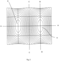
- Figure 2 shows a section of the mould in Figure 1 , from above, and contour lines are added to indicate the gradient of the slope of the elevation 8 and depression 9.
- each elevation and depression has a slope in the lateral direction as well as in the longitudinal direction.
- Depressions and elevations are arranged alternating and adjacent to each other in longitudinal direction, and in the transition from elevation to depression and vice versa, there will be a transition line with no elevation in either direction.
- a transition line is indicated in Figure 2 as C-C.
- the opposing edge walls 6, 7 of the cavity are closer to each other at the bottom of a depression or at the top of an elevation of the main walls, and further from each other at the transition between elevation and depression.
- Figure 1 the walls 6, 7 curves along the longitudinal direction.
- Figure 2 the edges of the section are closer along line B-B which is at the top/bottom of an elevation/depression than along line C-C which is at a transition between an elevation/depression.
- Figure 3 shows a lateral cross section of a mould, wherein the two parts 1, 2 of the housing are arranged in relation to each other and encloses the cavity 3.
- a lateral cross section is also referred to as a cross section in XY plane.
- Each elevation 8 or depression 9 extends along the whole lateral direction of the cavity, that is from edge wall 6 to edge wall 7, and thus the lateral cross section has the form of an arc.
- the main wall 4 of part 2 has a number of recesses and holes 10, to create a pattern on the tire tread.
- Figure 4 shows a longitudinal cross section of a part of a mould, wherein the two parts 1, 2 of the housing are arranged exploded, that is in distance to each other.
- a longitudinal cross section is also referred to as a cross section in YZ plane.
- the cross section has the form of an wave.
- edge wall 6 is a part of a side wall 11 of one part 2 of the housing.
- the other part 1 has a protruding flange 12, to be supported by the side wall 11 once the mould is mounted.
- the height of the edge wall 6, and thus the thickness of the cavity 3, will be given by the design of the side wall 11 and flange 12, as will be obvious to a skilled person.
- Figure 5 shows a cross section along a 0 plane for the cavity, also referred to as the xz plane.
- a cross section in the xz plane shows an elevation 8 of one part 1 of the mould, (the upper part in Figure 5 ) as well as a depression 9 of the other part of the mould 2, wherein the elevation 8 is arranged above , and partly in, the depression 9.
- the depressions 29 should be pressed from the lower side and upwards, as indicated by an arrow in Figure 7 , until they are inverted. Due to elastic properties of the material of the tire tread, this inverting procedure is possible. A small amount of strain energy may still be persistent after inverting, mainly due to the fact that the article does not have zero thickness. Then the tire tread will curve as shown in Figure 8 . For clarity reasons, the tire tread 23 in Figure 8 is shown with an even surface, that is without pattern 30.
- the depressions 29 of the tire tread 23 are inverted, it will be double curved, having a radius r in lateral direction, and radius R in longitudinal direction.
- the radii r and R are determined among other things by the slope of the elevations and depressions in lateral direction and longitudinal direction of the cavity.
- the gradient of the slopes are indicated by the contour lines in Figure 2 .
- the lateral distance from one edge of the element to the other, once the depressions are inverted is constant. This is shown as a constant side edge 27, 27 in Figure 8 .
- any segment Ax with longitudinal length Z of the element yields a corresponding segment Bx of the double curved element with angle W after any depressions are inverted, where angle W and length Z is proportional.
- the shape of the elevations are identical to the depressions.
- the shapes may be different, but the shape of any elevation or depression may be such as to yield a segment of the desired double curved shape, meaning that if a segment Ax is defined as between the transition into an elevation or depression and the transition out of the same elevation or depression, the segment would correspond to any segment Bx of a double curved shape with Angle W proportional to longitudinal length Z of Ax.
- a double curved shape with radius R can as such be obtained with elevations and depressions of varying amplitudes and wavelengths by adjusting the number of elevations and depression on the element in total.
Landscapes
- Engineering & Computer Science (AREA)
- Mechanical Engineering (AREA)
- Moulds For Moulding Plastics Or The Like (AREA)
- Casting Or Compression Moulding Of Plastics Or The Like (AREA)
- Springs (AREA)
- Processing And Handling Of Plastics And Other Materials For Molding In General (AREA)
- Heating, Cooling, Or Curing Plastics Or The Like In General (AREA)
- Tyre Moulding (AREA)
Applications Claiming Priority (2)
| Application Number | Priority Date | Filing Date | Title |
|---|---|---|---|
| NO20201223A NO346344B1 (en) | 2020-11-12 | 2020-11-12 | Mould and method for moulding double curved elements of elastomeric material |
| PCT/NO2021/050236 WO2022103274A1 (en) | 2020-11-12 | 2021-11-12 | Mould and method for moulding double curved elements of elastomeric material |
Publications (3)
| Publication Number | Publication Date |
|---|---|
| EP4244048A1 EP4244048A1 (en) | 2023-09-20 |
| EP4244048C0 EP4244048C0 (en) | 2025-03-05 |
| EP4244048B1 true EP4244048B1 (en) | 2025-03-05 |
Family
ID=78957494
Family Applications (1)
| Application Number | Title | Priority Date | Filing Date |
|---|---|---|---|
| EP21827702.8A Active EP4244048B1 (en) | 2020-11-12 | 2021-11-12 | Mould and method for moulding double curved elements of elastomeric material |
Country Status (18)
| Country | Link |
|---|---|
| US (1) | US20230398754A1 (https=) |
| EP (1) | EP4244048B1 (https=) |
| JP (1) | JP2023552074A (https=) |
| KR (1) | KR20230104925A (https=) |
| CN (1) | CN116600977A (https=) |
| AU (1) | AU2021377412A1 (https=) |
| CA (1) | CA3201473A1 (https=) |
| CL (1) | CL2023001355A1 (https=) |
| ES (1) | ES3032033T3 (https=) |
| HU (1) | HUE071371T2 (https=) |
| IL (1) | IL302829B2 (https=) |
| MA (1) | MA60438B1 (https=) |
| MX (1) | MX2023005573A (https=) |
| NO (1) | NO346344B1 (https=) |
| PH (1) | PH12023551320A1 (https=) |
| PL (1) | PL4244048T3 (https=) |
| WO (1) | WO2022103274A1 (https=) |
| ZA (1) | ZA202305437B (https=) |
Family Cites Families (9)
| Publication number | Priority date | Publication date | Assignee | Title |
|---|---|---|---|---|
| GB191407617A (en) * | 1914-03-26 | 1914-08-20 | John Liddle | Process and Apparatus for Making Rubber Articles and Product of the Process. |
| US4818203A (en) * | 1988-06-02 | 1989-04-04 | The Goodyear Tire & Rubber Company | System for injection molding elongated bodies |
| US7819153B2 (en) * | 2006-11-08 | 2010-10-26 | Bridgestone Americas Tire Operations, Llc | Tire including concave recesses in a circumferential tread |
| US8632715B2 (en) * | 2008-08-31 | 2014-01-21 | Michelin Recherche Et Technique S.A. | Contoured flat mold |
| RU2457950C1 (ru) * | 2008-08-31 | 2012-08-10 | Мишлен Решерш Э Текник С.А. | Плоская пресс-форма со сложным контуром |
| RU2014129805A (ru) * | 2011-12-20 | 2016-02-10 | Мишлен Решерш Э Текник С.А. | Поперечные канавки, обеспечивающие наличие газоотвода в протекторах для восстановленных шин |
| US10596774B2 (en) * | 2014-09-01 | 2020-03-24 | Compagnie Generale Des Etablissements Michelin | Dual mold replace center rib |
| ES2797075T3 (es) * | 2016-02-29 | 2020-12-01 | Technium As | Elemento para neumáticos |
| CN108724778B (zh) * | 2018-07-09 | 2024-05-07 | 常州市羊氏模具有限公司 | 车辆轮胎翻新模具 |
-
2020
- 2020-11-12 NO NO20201223A patent/NO346344B1/en unknown
-
2021
- 2021-11-12 US US18/252,554 patent/US20230398754A1/en active Pending
- 2021-11-12 PH PH1/2023/551320A patent/PH12023551320A1/en unknown
- 2021-11-12 HU HUE21827702A patent/HUE071371T2/hu unknown
- 2021-11-12 JP JP2023528286A patent/JP2023552074A/ja active Pending
- 2021-11-12 ES ES21827702T patent/ES3032033T3/es active Active
- 2021-11-12 EP EP21827702.8A patent/EP4244048B1/en active Active
- 2021-11-12 IL IL302829A patent/IL302829B2/en unknown
- 2021-11-12 WO PCT/NO2021/050236 patent/WO2022103274A1/en not_active Ceased
- 2021-11-12 MA MA60438A patent/MA60438B1/fr unknown
- 2021-11-12 AU AU2021377412A patent/AU2021377412A1/en not_active Abandoned
- 2021-11-12 PL PL21827702.8T patent/PL4244048T3/pl unknown
- 2021-11-12 CN CN202180081871.9A patent/CN116600977A/zh active Pending
- 2021-11-12 MX MX2023005573A patent/MX2023005573A/es unknown
- 2021-11-12 CA CA3201473A patent/CA3201473A1/en active Pending
- 2021-11-12 KR KR1020237019309A patent/KR20230104925A/ko active Pending
-
2023
- 2023-05-10 CL CL2023001355A patent/CL2023001355A1/es unknown
- 2023-05-18 ZA ZA2023/05437A patent/ZA202305437B/en unknown
Also Published As
| Publication number | Publication date |
|---|---|
| EP4244048A1 (en) | 2023-09-20 |
| NO346344B1 (en) | 2022-06-20 |
| AU2021377412A9 (en) | 2024-06-13 |
| ZA202305437B (en) | 2024-11-27 |
| KR20230104925A (ko) | 2023-07-11 |
| HUE071371T2 (hu) | 2025-08-28 |
| MA60438B1 (fr) | 2024-05-31 |
| MX2023005573A (es) | 2023-07-31 |
| PH12023551320A1 (en) | 2024-03-11 |
| WO2022103274A1 (en) | 2022-05-19 |
| NO20201223A1 (en) | 2022-05-13 |
| JP2023552074A (ja) | 2023-12-14 |
| CL2023001355A1 (es) | 2023-12-15 |
| CA3201473A1 (en) | 2022-05-19 |
| ES3032033T3 (en) | 2025-07-15 |
| EP4244048C0 (en) | 2025-03-05 |
| IL302829B1 (en) | 2024-10-01 |
| IL302829A (en) | 2023-07-01 |
| US20230398754A1 (en) | 2023-12-14 |
| IL302829B2 (en) | 2025-02-01 |
| MA60438A1 (fr) | 2023-11-30 |
| AU2021377412A1 (en) | 2023-06-15 |
| CN116600977A (zh) | 2023-08-15 |
| PL4244048T3 (pl) | 2025-07-14 |
Similar Documents
| Publication | Publication Date | Title |
|---|---|---|
| JP4312823B1 (ja) | 空気入りタイヤおよびタイヤ成形金型ならびに空気入りタイヤの製造方法 | |
| CN103732422B (zh) | 具有刀槽花纹密度可变的胎面以及圆形胎冠的轮胎 | |
| US20150013864A1 (en) | Tire With Pre-Formed Tread And Method Of Making Same | |
| KR20010013134A (ko) | 타이어 트래드 패턴 및 몰드 | |
| CN100475561C (zh) | 具有拱形胎肩的弹性体轮胎 | |
| CN109789603A (zh) | 轮胎硫化模具、轮胎硫化装置以及轮胎的制造方法 | |
| EP2517867B1 (en) | Blade for a mold, mold segment or mold comprising such a blade and method of securing a mold blade to a mold segment | |
| KR101917494B1 (ko) | 타이어 가류금형의 커프 성형용 블레이드와 이를 이용한 차량용 타이어 및 타이어 가류장치 | |
| EP4244048B1 (en) | Mould and method for moulding double curved elements of elastomeric material | |
| HK40095992B (en) | Mould and method for moulding double curved elements of elastomeric material | |
| HK40095992A (en) | Mould and method for moulding double curved elements of elastomeric material | |
| EP0305617A1 (en) | Tyre vulcanizing mould | |
| JP5023240B2 (ja) | 異形フラットモールド | |
| JP4518204B2 (ja) | 空気入りタイヤおよびタイヤ成形金型ならびに空気入りタイヤの製造方法 | |
| RU2457950C1 (ru) | Плоская пресс-форма со сложным контуром | |
| CN104602883B (zh) | 帘布层转向效应参数的模内调节 | |
| CN113905866B (zh) | 轮胎成形用模具及充气轮胎 | |
| KR20190073053A (ko) | 차량용 타이어 및 그 제조방법 | |
| WO2026077905A1 (en) | Tire tread for a tire and tire and curing mould to manufacture a tire tread | |
| JP2004034942A (ja) | 二輪車用空気入りタイヤおよびそれの製造方法 |
Legal Events
| Date | Code | Title | Description |
|---|---|---|---|
| STAA | Information on the status of an ep patent application or granted ep patent |
Free format text: STATUS: UNKNOWN |
|
| STAA | Information on the status of an ep patent application or granted ep patent |
Free format text: STATUS: THE INTERNATIONAL PUBLICATION HAS BEEN MADE |
|
| PUAI | Public reference made under article 153(3) epc to a published international application that has entered the european phase |
Free format text: ORIGINAL CODE: 0009012 |
|
| STAA | Information on the status of an ep patent application or granted ep patent |
Free format text: STATUS: REQUEST FOR EXAMINATION WAS MADE |
|
| 17P | Request for examination filed |
Effective date: 20230612 |
|
| AK | Designated contracting states |
Kind code of ref document: A1 Designated state(s): AL AT BE BG CH CY CZ DE DK EE ES FI FR GB GR HR HU IE IS IT LI LT LU LV MC MK MT NL NO PL PT RO RS SE SI SK SM TR |
|
| REG | Reference to a national code |
Ref country code: HK Ref legal event code: DE Ref document number: 40095992 Country of ref document: HK |
|
| DAV | Request for validation of the european patent (deleted) | ||
| DAX | Request for extension of the european patent (deleted) | ||
| GRAP | Despatch of communication of intention to grant a patent |
Free format text: ORIGINAL CODE: EPIDOSNIGR1 |
|
| STAA | Information on the status of an ep patent application or granted ep patent |
Free format text: STATUS: GRANT OF PATENT IS INTENDED |
|
| INTG | Intention to grant announced |
Effective date: 20240802 |
|
| GRAJ | Information related to disapproval of communication of intention to grant by the applicant or resumption of examination proceedings by the epo deleted |
Free format text: ORIGINAL CODE: EPIDOSDIGR1 |
|
| STAA | Information on the status of an ep patent application or granted ep patent |
Free format text: STATUS: REQUEST FOR EXAMINATION WAS MADE |
|
| GRAP | Despatch of communication of intention to grant a patent |
Free format text: ORIGINAL CODE: EPIDOSNIGR1 |
|
| STAA | Information on the status of an ep patent application or granted ep patent |
Free format text: STATUS: GRANT OF PATENT IS INTENDED |
|
| INTC | Intention to grant announced (deleted) | ||
| INTG | Intention to grant announced |
Effective date: 20241212 |
|
| GRAS | Grant fee paid |
Free format text: ORIGINAL CODE: EPIDOSNIGR3 |
|
| GRAA | (expected) grant |
Free format text: ORIGINAL CODE: 0009210 |
|
| STAA | Information on the status of an ep patent application or granted ep patent |
Free format text: STATUS: THE PATENT HAS BEEN GRANTED |
|
| AK | Designated contracting states |
Kind code of ref document: B1 Designated state(s): AL AT BE BG CH CY CZ DE DK EE ES FI FR GB GR HR HU IE IS IT LI LT LU LV MC MK MT NL NO PL PT RO RS SE SI SK SM TR |
|
| REG | Reference to a national code |
Ref country code: GB Ref legal event code: FG4D |
|
| REG | Reference to a national code |
Ref country code: CH Ref legal event code: EP |
|
| REG | Reference to a national code |
Ref country code: IE Ref legal event code: FG4D |
|
| REG | Reference to a national code |
Ref country code: DE Ref legal event code: R096 Ref document number: 602021027279 Country of ref document: DE |
|
| U01 | Request for unitary effect filed |
Effective date: 20250326 |
|
| U07 | Unitary effect registered |
Designated state(s): AT BE BG DE DK EE FI FR IT LT LU LV MT NL PT RO SE SI Effective date: 20250402 |
|
| PG25 | Lapsed in a contracting state [announced via postgrant information from national office to epo] |
Ref country code: RS Free format text: LAPSE BECAUSE OF FAILURE TO SUBMIT A TRANSLATION OF THE DESCRIPTION OR TO PAY THE FEE WITHIN THE PRESCRIBED TIME-LIMIT Effective date: 20250605 |
|
| PG25 | Lapsed in a contracting state [announced via postgrant information from national office to epo] |
Ref country code: NO Free format text: LAPSE BECAUSE OF FAILURE TO SUBMIT A TRANSLATION OF THE DESCRIPTION OR TO PAY THE FEE WITHIN THE PRESCRIBED TIME-LIMIT Effective date: 20250605 |
|
| REG | Reference to a national code |
Ref country code: ES Ref legal event code: FG2A Ref document number: 3032033 Country of ref document: ES Kind code of ref document: T3 Effective date: 20250715 |
|
| PG25 | Lapsed in a contracting state [announced via postgrant information from national office to epo] |
Ref country code: HR Free format text: LAPSE BECAUSE OF FAILURE TO SUBMIT A TRANSLATION OF THE DESCRIPTION OR TO PAY THE FEE WITHIN THE PRESCRIBED TIME-LIMIT Effective date: 20250305 |
|
| PG25 | Lapsed in a contracting state [announced via postgrant information from national office to epo] |
Ref country code: GR Free format text: LAPSE BECAUSE OF FAILURE TO SUBMIT A TRANSLATION OF THE DESCRIPTION OR TO PAY THE FEE WITHIN THE PRESCRIBED TIME-LIMIT Effective date: 20250606 |
|
| REG | Reference to a national code |
Ref country code: SK Ref legal event code: T3 Ref document number: E 46535 Country of ref document: SK |
|
| REG | Reference to a national code |
Ref country code: HU Ref legal event code: AG4A Ref document number: E071371 Country of ref document: HU |
|
| PG25 | Lapsed in a contracting state [announced via postgrant information from national office to epo] |
Ref country code: SM Free format text: LAPSE BECAUSE OF FAILURE TO SUBMIT A TRANSLATION OF THE DESCRIPTION OR TO PAY THE FEE WITHIN THE PRESCRIBED TIME-LIMIT Effective date: 20250305 |
|
| PGFP | Annual fee paid to national office [announced via postgrant information from national office to epo] |
Ref country code: TR Payment date: 20250924 Year of fee payment: 5 Ref country code: PL Payment date: 20250917 Year of fee payment: 5 |
|
| PGFP | Annual fee paid to national office [announced via postgrant information from national office to epo] |
Ref country code: CZ Payment date: 20250915 Year of fee payment: 5 |
|
| PGFP | Annual fee paid to national office [announced via postgrant information from national office to epo] |
Ref country code: SK Payment date: 20250925 Year of fee payment: 5 |
|
| PG25 | Lapsed in a contracting state [announced via postgrant information from national office to epo] |
Ref country code: IS Free format text: LAPSE BECAUSE OF FAILURE TO SUBMIT A TRANSLATION OF THE DESCRIPTION OR TO PAY THE FEE WITHIN THE PRESCRIBED TIME-LIMIT Effective date: 20250705 |
|
| PGFP | Annual fee paid to national office [announced via postgrant information from national office to epo] |
Ref country code: HU Payment date: 20251003 Year of fee payment: 5 |
|
| U20 | Renewal fee for the european patent with unitary effect paid |
Year of fee payment: 5 Effective date: 20251113 |
|
| PGFP | Annual fee paid to national office [announced via postgrant information from national office to epo] |
Ref country code: GB Payment date: 20251114 Year of fee payment: 5 |
|
| PLBE | No opposition filed within time limit |
Free format text: ORIGINAL CODE: 0009261 |
|
| STAA | Information on the status of an ep patent application or granted ep patent |
Free format text: STATUS: NO OPPOSITION FILED WITHIN TIME LIMIT |
|
| REG | Reference to a national code |
Ref country code: CH Ref legal event code: L10 Free format text: ST27 STATUS EVENT CODE: U-0-0-L10-L00 (AS PROVIDED BY THE NATIONAL OFFICE) Effective date: 20260114 |
|
| U1N | Appointed representative for the unitary patent procedure changed after the registration of the unitary effect |
Representative=s name: ACAPO ONSAGERS AS; NO |
|
| PGFP | Annual fee paid to national office [announced via postgrant information from national office to epo] |
Ref country code: ES Payment date: 20251212 Year of fee payment: 5 |
|
| 26N | No opposition filed |
Effective date: 20251208 |