EP4243563B1 - Kernnetzwerkbewusstsein eines benutzergerät-rrc-zustands - Google Patents
Kernnetzwerkbewusstsein eines benutzergerät-rrc-zustands Download PDFInfo
- Publication number
- EP4243563B1 EP4243563B1 EP23188744.9A EP23188744A EP4243563B1 EP 4243563 B1 EP4243563 B1 EP 4243563B1 EP 23188744 A EP23188744 A EP 23188744A EP 4243563 B1 EP4243563 B1 EP 4243563B1
- Authority
- EP
- European Patent Office
- Prior art keywords
- network node
- rrc
- state
- notification
- core network
- Prior art date
- Legal status (The legal status is an assumption and is not a legal conclusion. Google has not performed a legal analysis and makes no representation as to the accuracy of the status listed.)
- Active
Links
Images





Classifications
-
- H—ELECTRICITY
- H04—ELECTRIC COMMUNICATION TECHNIQUE
- H04W—WIRELESS COMMUNICATION NETWORKS
- H04W64/00—Locating users or terminals or network equipment for network management purposes, e.g. mobility management
-
- H—ELECTRICITY
- H04—ELECTRIC COMMUNICATION TECHNIQUE
- H04W—WIRELESS COMMUNICATION NETWORKS
- H04W76/00—Connection management
- H04W76/20—Manipulation of established connections
- H04W76/27—Transitions between radio resource control [RRC] states
-
- H—ELECTRICITY
- H04—ELECTRIC COMMUNICATION TECHNIQUE
- H04W—WIRELESS COMMUNICATION NETWORKS
- H04W92/00—Interfaces specially adapted for wireless communication networks
- H04W92/04—Interfaces between hierarchically different network devices
- H04W92/045—Interfaces between hierarchically different network devices between access point and backbone network device
Definitions
- wireless devices also known as mobile stations, terminals, and/or User Equipment (UE), communicate via a Radio-Access Network (RAN) with one or more core networks.
- the RAN covers a geographical area that is divided into cells. Each cell is served by a base station (e.g., a radio base station (RBS), or network node, which in some networks may also be referred to as, for example, a "NodeB", "eNodeB” or “eNB”).
- RBS radio base station
- a cell is a geographical area where radio coverage is provided by the radio base station at a base station site or an antenna site in case the antenna and the radio base station are not collocated.
- One radio base station may serve one or more cells.
- a Universal Mobile Telecommunications System is a third generation (3G) mobile communication system that evolved from the second generation (2G) Global System for Mobile Communications (GSM).
- the UMTS terrestrial radio-access network is essentially a RAN using wideband code-division multiple access (WCDMA) and/or HighSpeed Packet Access (HSPA) to communicate with user equipment.
- WCDMA wideband code-division multiple access
- HSPA HighSpeed Packet Access
- telecommunications suppliers propose and agree upon standards for third generation networks and UTRAN specifically, and investigate enhanced data rate and radio capacity.
- 3GPP Third Generation Partnership Project
- telecommunications suppliers propose and agree upon standards for third generation networks and UTRAN specifically, and investigate enhanced data rate and radio capacity.
- a controller node such as a radio network controller (RNC) or a base station controller (BSC) that supervises and coordinates various activities of the plural base stations connected thereto.
- RNCs are typically connected to one or more core networks.
- PDCP Packet Data Convergence Protocol
- RRC control plane
- user plane i.e., user data received via GPRS tunneling protocol-user tunneling (GTP-U) signaling
- a main function of the control plane is ciphering/deciphering and integrity protection.
- Main functions of the user plane include: ciphering/deciphering, header compression and decompression using Robust Header Compression (ROHC) and in-sequence delivery, duplicate detection and retransmission.
- ROHC Robust Header Compression
- the Radio Link Control (RLC) layer provides services for the PDCP layer.
- RLC Radio Link Control
- Main functions for both control and user plane include: segmentation/concatenation, retransmission handling, duplicate detection, and in-sequence delivery to higher layers.
- the Medium Access Control provides services to the RLC layer in the form of logical channels, and performs mapping between the logical channels and transport channels.
- Main MAC functions include: uplink and downlink scheduling, scheduling information reporting, Hybrid Automatic Repeat reQuest (HARQ) retransmissions, and multiplexing/de-multiplexing data across multiple component carriers for carrier aggregation.
- HARQ Hybrid Automatic Repeat reQuest
- the Physical Layer provides services to the MAC layer in the form of transport channels and handles mapping of transport channels to physical channels.
- the RAN context information may further include additional information, such as, for example, radio access capabilities of the wireless device, previous mobility or traffic history of the wireless device, etc.
- the above described functionality of the network node may be deployed in different ways.
- all the protocol layers and related functionality are deployed in the same physical node, including the antenna.
- a Pico or Femto eNodeB is another example.
- a Main-Remote split In this case, the eNodeB is divided into a main unit and a remote unit.
- the main unit may also be referred to as a Digital Unit (DU), and the remote unit also referred to as a Remote Radio Unit (RRU).
- the main unit comprises all the protocol layers, except the lower parts of the PHY layer, which are instead placed in the remote unit.
- remote unit and the antenna are co-located. This may be referred to as an Antenna Integrated Radio (AIR) system.
- AIR Antenna Integrated Radio
- a RAN may handle inactive UEs.
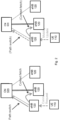
- the 3GPP contribution R3-161290 (available from www.3gpp.org at /ftp/tsg_ran/WG3_Iu/TSGR3_92/Docs/R3-161290.zip) to the 3GPP RAN 3 WG meeting in May 2016 includes a proposal for a RAN controlled inactive state as described below.
- core network node 320 When a packet arrives for delivery to UE 110, core network node 320 contacts network node 120b. Network node 120b pages UE 110. Network node 120b also instructs network nodes 120a and 120b to page UE 110.
- UE 110 When a UE 110 has data to transmit, UE 110 sends a connection request or mobility update to network node 120a, for example.
- Network node 120a sends a path switch request to core network node 320.
- Network node 120a also fetches the context of UE 110 from network node 120b.
- CN 105 850 176 A discloses a congestion control method for a core network node in a mobile communication system including the following method steps: the first information with congestion association is received from at least one base station; a subscriber equipment (UE) information request message is sent to a Mobility Management Entity (MME), to be used for a second information request that associates with at least one UE corresponding to a base station; the UE information response message including the second information request is received from the MME; and the second information request is sent to other core network nodes.
- MME Mobility Management Entity
- a problem with the particular state machine is that the transitions between RRC CONNECTED and RRC CONNECTED INACTIVE are considered to be conducted without signaling to the next generation core network (NGCN).
- NGCN next generation core network
- FIGURES 4-13B of the drawings like numerals being used for like and corresponding parts of the various drawings.
- LTE and NR are used throughout this disclosure as example cellular systems, but the ideas presented herein may apply to other wireless communication systems as well.
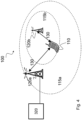
- FIGURE 4 is a block diagram illustrating an example wireless network, according to a particular embodiment.
- Wireless network 100 includes one or more wireless devices 110 (such as mobile phones, smart phones, laptop computers, tablet computers, MTC devices, or any other devices that can provide wireless communication) and a plurality of network nodes 120 (such as base stations or eNodeBs).
- Network node 120 serves coverage area 115 (also referred to as cell 115).
- wireless devices 110 that are within coverage of radio network node 120 (e.g., within cell 115 served by network node 120) communicate with radio network node 120 by transmitting and receiving wireless signals 130.
- wireless devices 110 and radio network node 120 may communicate wireless signals 130 containing voice traffic, data traffic, and/or control signals.
- a network node 120 communicating voice traffic, data traffic, and/or control signals to wireless device 110 may be referred to as a serving network node 120 for the wireless device 110.
- wireless device 110 may be referred to by the non-limiting term "UE_"
- a UE may include any type of wireless device capable of communicating with a network node or another UE over radio signals.
- the UE may comprise radio communication device, target device, device to device (D2D) UE, machine type UE or UE capable of machine to machine communication (M2M), a sensor equipped with UE, iPAD, Tablet, mobile terminals, smart phone, laptop embedded equipped (LEE), laptop mounted equipment (LME), USB dongles, Customer Premises Equipment (CPE), etc.
- D2D device to device
- M2M machine to machine communication
- iPAD machine to machine communication
- Tablet mobile terminals
- smart phone laptop embedded equipped (LEE), laptop mounted equipment (LME), USB dongles, Customer Premises Equipment (CPE), etc.
- LEE laptop embedded equipped
- LME laptop mounted equipment
- CPE Customer Premises Equipment
- network node 120 may include any type of network node such as a base station, radio base station, base transceiver station, base station controller, network controller, evolved Node B (eNB), Node B, multi-RAT base station, Multi-cell/multicast Coordination Entity (MCE), relay node, access point, radio access point, Remote Radio Unit (RRU) Remote Radio Head (RRH), a core network node (e.g., MME, SON node, a coordinating node, etc.), or even an external node (e.g., 3rd party node, a node external to the current network), etc.
- a core network node e.g., MME, SON node, a coordinating node, etc.
- an external node e.g., 3rd party node, a node external to the current network
- Network 100 may include carrier aggregation.
- wireless device 110 may be served by both network node 120a and 120b and communicate wireless signals 130 with both network node 120a and 120b.
- the radio network controller may interface with core network node 320 via an interconnecting wired or wireless network.
- the interconnecting network may refer to any interconnecting system capable of transmitting audio, video, signals, data, messages, or any combination of the preceding.
- the interconnecting network may include all or a portion of a public switched telephone network (PSTN), a public or private data network, a local area network (LAN), a metropolitan area network (MAN), a wide area network (WAN), a local, regional, or global communication or computer network such as the Internet, a wireline or wireless network, an enterprise intranet, or any other suitable communication link, including combinations thereof.
- PSTN public switched telephone network
- LAN local area network
- MAN metropolitan area network
- WAN wide area network
- Internet a local, regional, or global communication or computer network
- wireline or wireless network an enterprise intranet, or any other suitable communication link, including combinations thereof.
- core network node 320 may manage the establishment of communication sessions and various other functionalities for wireless devices 110.
- wireless devices 110 may exchange certain signals with core network node 320 using the non-access stratum layer.
- non-access stratum signaling signals between wireless devices 110 and core network node 320 may be transparently passed through the radio access network.
- network nodes 120 may interface with one or more network nodes 120 over an internode interface, such as, for example, an X2 interface.
- Wireless device 110 may include state information, such as radio resource control (RRC) state information
- RRC radio resource control
- Wireless device 110 may be in one of an IDLE, CONNECTED, or CONNECTED INACTIVE RRC state.
- Network node 120 (or radio node controller) may control the state of wireless device 110.
- network node 120 may send notifications to core network node 320 about the state, or state transitions of, wireless device 110.
- core network node 320 may register or subscribe to a state change notification for wireless device 110.
- network node 120 may notify core network node 320 of the state change.
- the notification may include location information. State notifications are described in more detail below with respect to FIGURES 5-10 .
- each radio network node 120 may use any suitable radio access technology, such as long term evolution (LTE), LTE-Advanced, NR, UMTS, HSPA, GSM, cdma2000, WiMax, WiFi, and/or other suitable radio access technology.
- Wireless network 100 may include any suitable combination of one or more radio access technologies. For purposes of example, various embodiments may be described within the context of certain radio access technologies. However, the scope of the disclosure is not limited to the examples and other embodiments could use different radio access technologies.
- a wireless network may include one or more wireless devices and one or more different types of radio network nodes capable of communicating with the wireless devices.
- the network may also include any additional elements suitable to support communication between wireless devices or between a wireless device and another communication device (such as a landline telephone).
- a wireless device may include any suitable combination of hardware and/or software.
- a wireless device such as wireless device 110
- a network node may include any suitable combination of hardware and/or software.
- a network node, such as network node 120 may include the components described below with respect to FIGURE 12A .
- a core network node may include any suitable combination of hardware and/or software.
- a core network node such as core network node 320, may include the components described below with respect to FIGURE 13A .
- the embodiments disclosed herein are based on the principle that the core network becomes aware of whether a UE is in RRC CONNECTED INACTIVE or might become a subject to RRC CONNECTED INACTIVE.
- Two groups of embodiments are disclosed-subscription-based notification and autonomous RAN-initiated notification. These primary embodiments, including variations thereof, are described in more detail below.
- Particular embodiments include subscription based notification.
- the CN subscribes to the RAN so the RAN provides information about the UE, including whether UE is in RRC CONNECTED or RRC CONNECTED INACTIVE, to the CN.
- the information may be used by the CN to determine how to manage certain functions, e.g., with regards to knowledge about the granularity the UE's location.
- Particular embodiments include a stand-alone subscription procedure that includes a procedure on the CN/RAN interface.
- An example is illustrated in FIGURE 4 .
- FIGURE 5 is a sequence diagram illustrating a core network subscription to the radio access network, according to some embodiments.
- a UE is connected to the network and can receive and transfer user plane data and control plane data.
- the core network sends to the RAN a request to subscribe to UE transitions between RRC CONNECTED and RRC CONNECTED INACTIVE.
- the request may include parameters describing details of the subscription and/or specific data requests (e.g., current location request).
- the RAN provides a response to the core network indicating whether the RAN accepted the subscription request from step 2 and provides details related to the accepted subscription and/or requested data (e.g., current location response).
- the RAN upon the UE transition (e.g., from RRC CONNECTED to RRC CONNECTED INACTIVE), the RAN sends a notification to the core network.
- the notification may include parameters describing UE behavior configured by the network. The parameters may have been requested in step 2.
- Another alternative is to include a subscription mechanism in the Connection Setup procedure, i.e. already in step 1 in Figure 4 .
- the alternative embodiment is detailed below based on Initial UE Context Setup procedure in LTE.
- the new function is shown in relation to current standardized procedure.
- the embodiment may be described in relation to the Connection Setup procedure described in Section 8.3.1 of 3GPP TS 36.413v13.3.0 (the entirety of which is incorporated herein by reference).
- the subscription procedure is embedded in the UE context setup procedure on the CN/RAN interface.
- the purpose of the Initial Context Setup procedure is to establish the necessary overall initial UE Context including E-RAB context, the Security Key, Handover Restriction List, UE Radio capability and UE Security Capabilities etc.
- the procedure uses UE-associated signaling. An example is illustrated in FIGURE 6 .
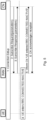
- FIGURE 6 is a signaling diagram illustrating an initial context setup procedure, according to some embodiments.
- the signaling diagram is a reproduction of Figure 8.3.1.2-1 from 3GPP TS 36.413v13.3.0.
- the INITIAL CONTEXT SETUP REQUEST message shall contain within the E-RAB to be Setup List IE the information required by the eNB to build the new E-RAB configuration consisting of at least one additional E-RAB.
- the E-RAB to be Setup Item IE may contain:
- the INITIAL CONTEXT SETUP REQUEST message may contain
- the INITIAL CONTEXT SETUP REQUEST message shall contain the Subscriber Profile ID for RAT/Frequency priority IE, if available in the MME.
- Correlation ID IE is included in the INITIAL CONTEXT SETUP REQUEST message towards the eNB with L-GW function for LIPA operation, then the eNB shall use this information for LIPA operation for the concerned E-RAB.
- the eNB shall use this information for SIPTO@LN operation for the concerned E-RAB.
- Bearer Type IE is included in the INITIAL CONTEXT SETUP REQUEST message and is set to "non IP", then the eNB shall not perform header compression for the concerned E-RAB.
- the target eNB shall, if supported, use it to determine the characteristics of the UE for subsequent handling.
- the eNB shall, if supported, store this information and may use it to determine the RRC connection time.
- the eNB Upon receipt of the INITIAL CONTEXT SETUP REQUEST message the eNB shall
- the eNB shall use the information in the Handover Restriction List IE if present in the INITIAL CONTEXT SETUP REQUEST message to
- the eNB shall consider that no roaming and no access restriction apply to the UE.
- the eNB shall also consider that no roaming and no access restriction apply to the UE when:
- eNB shall, if supported, initiate the requested trace function as described in TS 32.422. In particular, the eNB shall, if supported:
- the CS Fallback Indicator IE is included in the INITIAL CONTEXT SETUP REQUEST message, it indicates that the UE Context to be set-up is subject to CS Fallback.
- the eNB shall reply with the INITIAL CONTEXT SETUP RESPONSE message and then act as defined in TS 23.272.
- the Registered LAI IE is included in the INITIAL CONTEXT SETUP REQUEST message, it indicates that the eNB may take the Registered LAI IE into account when selecting the target cell or frequency and then act as defined in TS 23.272.
- the UE Security Capabilities IE included in the INITIAL CONTEXT SETUP REQUEST message only contains the EIA0 algorithm as defined in TS 33.401 and if this EIA0 algorithm is defined in the configured list of allowed integrity protection algorithms in the eNB (TS 33.401), the eNB shall take it into use and ignore the keys received in the Security Key IE.
- the eNB shall, if supported, store this information in the UE context and use it for subsequent X2 handovers.
- the eNB shall, if supported, store this information in the UE context and use it for subsequent X2 handovers.
- the eNB shall use it, if supported, together with information in the Management Based MDT PLMN List IE, if available in the UE context, to allow subsequent selection of the UE for management based MDT defined in TS 32.422.
- the eNB shall, if supported, consider that User Plane CIoT EPS Optimisation as specified in TS 23.401 is supported for the UE.
- the eNB shall report to the MME, in the INITIAL CONTEXT SETUP RESPONSE message, the successful establishment of the security procedures with the UE, and, the result for all the requested E-RABs in the following way:
- the cause value should be precise enough to enable the MME to know the reason for the unsuccessful establishment, e.g., "Radio resources not available", "Failure in the Radio Interface Procedure".
- the eNB evaluates its contents and reply to the CN in the INITIAL CONTEXT SETUP RESPONSE message with the result of the subscription request, i.e. whether eNB will provide the information subscribed to from the CN and about the way the information (or a subset of it) will be provided.
- This message is sent by the MME to request the setup of a UE context.
- This message is sent by the eNB to confirm the setup of a UE context.
- the CN may send a request to the RAN for a subscription to provide different information.
- Examples include, but are not limited to, subscription to report transitions between active state (i.e., RRC_CONNECTED) and connected inactive state.
- Another example is to report location information (e.g., to report a change of location at cell level, at registration area level, or at tracking area level, etc.).
- Another example is to report both types of information together (i.e., indication of state transition and location information).
- the RAN may respond by acknowledging subscription to the requested information, which will trigger future reporting via new or existing procedures both in acknowledged (Class 1) and unacknowledged (Class2) mode, or by rejecting the subscription.
- Another way to encode the IEs in the request and response messages would be for the CN to list a number of information elements that the RAN is requesting a subscription for reporting.
- the RAN replies with an equivalent list, where the information for which subscription is accepted are included and where the information for which subscription is not acknowledged are not included.
- the CN includes a request for provisioning of certain type of information upon occurrence of specific events at UE context creation. Upon positive response from the eNB to the CN that the information will be provided as per configured rules, the RAN will signal to the CN the requested information when the configured events occur.
- Such signalling may happen in various forms.
- the signalling may happen via a new Class 2 procedure, which includes the requested information.
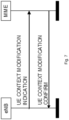
- the signalling may occur via an existing procedure such as the UE Context Modification Indication/Confirm, which is illustrated in FIGURE 7 .
- FIGURE 7 is a signaling diagram illustrating a user equipment context modification indication, according to some embodiments.
- the eNB indicates the information configured for reporting by the CN in the UE Context Modification Indication.
- the CN confirms the correct acceptance of such information in the UE Context Modification Confirm.
- the information exchange between RAN and CN may be supported via procedures that transport NAS PDUs.
- the request from the CN to subscribe to UE transitions between RRC CONNECTED and RRC CONNECTED INACTIVE may be provided via the DL NAS TRANSPORT procedure.
- This procedure may include potential parameters describing details of the subscription and optionally specific data (e.g., current location request) request.
- the RAN may reply to this request via the UL NAS TRANSPORT or other procedures to transport NAS PDUs in uplink.
- This procedure may indicate whether the RAN accepted the subscription request and provides details related to the accepted subscription and data if requested (e.g., current location response). Alternatively, the procedure may only include the requested data if the events triggering data reporting have occurred.
- a second group of embodiments include autonomous RAN initiated core network notification.
- the core network notification procedure may be autonomous, initiated by the RAN without core network subscription.
- Particular embodiments include standalone autonomous RAN initiated core network notification procedure, which may include a procedure on the CN/RAN interface.
- the RAN notifies the core network at any time it considers a UE becomes potentially subject to RRC CONNECTED INACTIVE state.
- An example is illustrated in FIGURE 8 .
- FIGURE 8 is a sequence diagram illustrating an autonomous notification to the core network from the radio access network, according to some embodiments.
- a UE is connected to the network and can receive and transfer user plane data and control plane data.
- the RAN concludes that the UE could potentially be subject to RRC CONNECTED INACTIVE. This determination may be based on a variety of different factors, including but not limited to activity pattern.
- the RAN indicates to the core network that the UE may potentially, e.g. based on its activity pattern, be subject to RRC CONNECTED INACTIVE.
- the CN acknowledges the reception of the notification from step 3.
- the CN used the indication received from RAN in step 3, for example, when managing features that rely on knowledge about the UE location.
- connection Setup procedure i.e. already in step 1 in Figure 6 .
- This is detailed below based on Initial UE Context Setup procedure in LTE.
- Particular embodiments include an embedded autonomous RAN initiated core network notification procedure.
- the subscription procedure is embedded in the UE context setup procedure on the CN/RAN interface.
- the new function is shown in relation to current standardized procedure.
- the embodiment may be described in relation to the Connection Setup procedure described in Section 8.3.1 of 3GPP TS 36.413v13.3.0.
- the purpose of the Initial Context Setup procedure is to establish the necessary overall initial UE Context including E-RAB context, the Security Key, Handover Restriction List, UE Radio capability and UE Security Capabilities etc.
- the procedure uses UE-associated signaling.
- FIGURE 6 An example is illustrated in FIGURE 6 (reproduced from Figure 8.3.1.2-1 of 3GPP TS 36.413v13.3.0).
- the EPC In case of the establishment of an E-RAB the EPC must be prepared to receive user data before the INITIAL CONTEXT SETUP RESPONSE message has been received by the MME. If no UE-associated logical S1-connection exists, the UE-associated logical S1-connection shall be established at reception of the INITIAL CONTEXT SETUP REQUEST message.
- the INITIAL CONTEXT SETUP REQUEST message shall contain within the E-RAB to be Setup List IE the information required by the eNB to build the new E-RAB configuration consisting of at least one additional E-RAB.
- the E-RAB to be Setup Item IE may contain:
- the INITIAL CONTEXT SETUP REQUEST message may contain
- the INITIAL CONTEXT SETUP REQUEST message shall contain the Subscriber Profile ID for RAT/Frequency priority IE, if available in the MME.
- Correlation ID IE is included in the INITIAL CONTEXT SETUP REQUEST message towards the eNB with L-GW function for LIPA operation, then the eNB shall use this information for LIPA operation for the concerned E-RAB.
- the eNB shall use this information for SIPTO@LN operation for the concerned E-RAB.
- Bearer Type IE is included in the INITIAL CONTEXT SETUP REQUEST message and is set to "non IP", then the eNB shall not perform header compression for the concerned E-RAB.
- the target eNB shall, if supported, use it to determine the characteristics of the UE for subsequent handling.
- the eNB shall, if supported, store this information and may use it to determine the RRC connection time.
- the eNB shall use the information in the Handover Restriction List IE if present in the INITIAL CONTEXT SETUP REQUEST message to
- eNB shall, if supported, initiate the requested trace function as described in TS 32.422. In particular, the eNB shall, if supported:
- the CS Fallback Indicator IE is included in the INITIAL CONTEXT SETUP REQUEST message, it indicates that the UE Context to be set-up is subject to CS Fallback.
- the eNB shall reply with the INITIAL CONTEXT SETUP RESPONSE message and then act as defined in TS 23.272.
- the Registered LAI IE is included in the INITIAL CONTEXT SETUP REQUEST message, it indicates that the eNB may take the Registered LAI IE into account when selecting the target cell or frequency and then act as defined in TS 23.272.
- the UE Security Capabilities IE included in the INITIAL CONTEXT SETUP REQUEST message only contains the EIA0 algorithm as defined in TS 33.401 and if this EIA0 algorithm is defined in the configured list of allowed integrity protection algorithms in the eNB (TS 33.401), the eNB shall take it into use and ignore the keys received in the Security Key IE.
- the eNB shall, if supported, store this information in the UE context and use it for subsequent X2 handovers.
- the eNB shall, if supported, store this information in the UE context and use it for subsequent X2 handovers.
- the eNB shall use it, if supported, together with information in the Management Based MDT PLMN List IE, if available in the UE context, to allow subsequent selection of the UE for management based MDT defined in TS 32.422.
- the eNB shall, if supported, consider that User Plane CIoT EPS Optimization as specified in TS 23.401 is supported for the UE.
- the eNB shall report to the MME, in the INITIAL CONTEXT SETUP RESPONSE message, the successful establishment of the security procedures with the UE, and, the result for all the requested E-RABs in the following way:
- the cause value should be precise enough to enable the MME to know the reason for the unsuccessful establishment, e.g., "Radio resources not available", "Failure in the Radio Interface Procedure".
- RAN can indicate to the CN that a UE might become subject to RRC CONNECTED INACTIVE.
- Particular embodiments performed in a network node may be generalized by FIGURE 9 .
- Particular embodiments performed in a core network node may be generalized by FIGURE 10 .
- FIGURE 9 is a flow diagram illustrating an example method in a network node, according to some embodiments. In particular embodiments, one or more steps of FIGURE 9 may be performed by network node 120 of wireless network 100 described with respect to FIGURE 4 .
- the method begins at step 912, where a network node receives a subscription request to receive a notification of a UE transition between a first RRC state and a second RRC state.
- the network node 120 may receive a subscription request from core network node 320 to be notified of a transition of wireless device 110 from a RRC CONNECTED STATE to an RRC CONNECTED INACTIVE state (or, exemplary, vice versa).
- the subscription request may include a request to receive location information of the UE.
- the subscription request includes a periodicity for receiving the notification. The periodicity specifies whether the notification is a one-time notification or a notification for each subsequent transition of the UE between the first RRC state and the second RRC state. In some embodiments, the request may include additional information.
- the network node may receive the subscription request according to any of the embodiments or examples described above with respect to FIGURES 6-8 .
- the network node may optionally send a subscription response indicating that the network node will provide the notification.
- network node 120 may provide a response to core network node 320 that network node 120 accepts the subscription and will provide all or some of the requested information to core network node 320.
- the network node may send a subscription response according to any of the embodiments or examples described above with respect to FIGURES 6-8 .
- network node 120 may not provide a confirmation at all, and the method may continue directly to step 916.
- the network node determines whether the UE transitioned between the first RRC state and the second RRC state. For example, network node 120 may determine that wireless device 110 transitioned, or is about to transition, from a RRC CONNECTED STATE to a RRC CONNECTED INACTIVE state (or vice versa). If the state transition occurred, the method continues to step 918.
- the network node sends the notification of the transition of the UE between the first RRC state and the second RRC state to the core network node
- the network node 120 sends the notification to core network node 320.
- the notification may include information about the state change (e.g., from state and/or to state), location information, or any other suitable information.
- the network node may send the notification in close temporal proximity to the occurrence of the state transition. In some embodiments, the network node may send the notification at scheduled intervals.
- the notification may comprise a one-time notification, or the notifications may continue for every state transition until the network node receives a cancel subscription request.
- the network node may send the notification according to any of the embodiments or examples described above with respect to FIGURES 6-8 .
- FIGURE 10 is a flow diagram illustrating an example method in a core network node, according to some embodiments. In particular embodiments, one or more steps of FIGURE 10 may be performed by core network node 320 of wireless network 100 described with respect to FIGURE 4 .
- a core network node sends a subscription request to receive a notification of a UE transition between a first RRC state and a second RRC state.
- core network node 320 may send a subscription request to network node 120 to be notified of a transition of wireless device 110 from a RRC CONNECTED STATE to an RRC CONNECTED INACTIVE state (or vice versa).
- the subscription request may include a request to receive location information of the UE.
- the subscription request may include a periodicity for receiving the notification. The periodicity specifies whether the notification is a one-time notification or a notification for each subsequent transition of the UE between the first RRC state and the second RRC state. In some embodiments, the request may include additional information.
- the core network node may send the subscription request according to any of the embodiments or examples described above with respect to FIGURES 6-8 .
- the core network node may optionally receive a subscription response indicating that the network node will provide the notification.
- core network node 320 may receive a response from network node 120 that network node 120 accepts the subscription and will provide all or some of the requested information to core network node 320.
- the core network node may receive a subscription response according to any of the embodiments or examples described above with respect to FIGURES 6-8 .
- network node 120 may not provide a confirmation at all, and the method may continue directly to step 1016.
- the core network node receives the notification from the network node. For example, upon network node 120 determining that wireless device 110 transitioned, or is about to transition, from a RRC CONNECTED STATE to a RRC CONNECTED INACTIVE state (or vice versa), core network node 120 may receive the notification from network node 120.
- the core network node may receive the notification according to any of the embodiments or examples described above with respect to FIGURES 6-8 .
- the core network node modifies an operation of the core network node with respect to the UE based on the received notification. For example, core network node 320 may perform an operation dependent on the location of wireless device 110. Core network node 320 may use location information received in the notification to perform the operation. Core network node 320 may modify an operation according to any of the embodiments or examples described above with respect to FIGURES 6-8 .
- FIGURE 11 is a block diagram illustrating an example embodiment of a wireless device.
- the wireless device is an example of the wireless devices 110 illustrated in FIGURE 4 .
- the wireless device is capable of transitioning between RRC states.
- a wireless device include a mobile phone, a smart phone, a PDA (Personal Digital Assistant), a portable computer (e.g., laptop, tablet), a sensor, a modem, a machine type (MTC) device / machine to machine (M2M) device, laptop embedded equipment (LEE), laptop mounted equipment (LME), USB dongles, a device-to-device capable device, a vehicle-to-vehicle device, or any other device that can provide wireless communication.
- the wireless device includes transceiver 1110, processing circuitry 1120, memory 1130, and power source 1140.
- transceiver 1110 facilitates transmitting wireless signals to and receiving wireless signals from wireless network node 120 (e.g., via an antenna), processing circuitry 1120 executes instructions to provide some or all of the functionality described herein as provided by the wireless device, and memory 1130 stores the instructions executed by processing circuitry 1120.
- Power source 1140 supplies electrical power to one or more of the components of wireless device 110, such as transceiver 1110, processing circuitry 1120, and/or memory 1130.
- Processing circuitry 1120 includes any suitable combination of hardware and software implemented in one or more integrated circuits or modules to execute instructions and manipulate data to perform some or all of the described functions of the wireless device.
- processing circuitry 1120 may include, for example, one or more computers, one more programmable logic devices, one or more central processing units (CPUs), one or more microprocessors, one or more applications, and/or other logic, and/or any suitable combination of the preceding.
- Processing circuitry 1120 may include analog and/or digital circuitry configured to perform some or all of the described functions of wireless device 110.
- processing circuitry 1120 may include resistors, capacitors, inductors, transistors, diodes, and/or any other suitable circuit components.
- Memory 1130 is generally operable to store computer executable code and data.
- Examples of memory 1130 include computer memory (e.g., Random Access Memory (RAM) or Read Only Memory (ROM)), mass storage media (e.g., a hard disk), removable storage media (e.g., a Compact Disk (CD) or a Digital Video Disk (DVD)), and/or or any other volatile or non-volatile, non-transitory computer-readable and/or computer-executable memory devices that store information.
- RAM Random Access Memory
- ROM Read Only Memory
- mass storage media e.g., a hard disk
- removable storage media e.g., a Compact Disk (CD) or a Digital Video Disk (DVD)
- CD Compact Disk
- DVD Digital Video Disk
- Power source 1140 is generally operable to supply electrical power to the components of wireless device 110.
- Power source 1140 may include any suitable type of battery, such as lithium-ion, lithium-air, lithium polymer, nickel cadmium, nickel metal hydride, or any other suitable type of battery for supplying power to a wireless device.
- wireless device may include additional components (beyond those shown in FIGURE 11 ) responsible for providing certain aspects of the wireless device's functionality, including any of the functionality described above and/or any additional functionality (including any functionality necessary to support the solution described above).
- FIGURE 12A is a block diagram illustrating an example embodiment of a network node.
- the network node is an example of the network node 120 illustrated in FIGURE 4 .
- the network node is capable of receiving a request to receive a notification of a transition of a UE between a first RRC state and a second RRC state; determining the UE transitioned between the first RRC state and the second RRC state; and sending the notification of the transition of the UE between the first RRC state and the second RRC state to a core network node.
- the network node may send, to the core network node, a subscription response indicating that the network node will provide the notification.
- Network node 120 can be an eNodeB, a nodeB, a base station, a wireless access point (e.g., a Wi-Fi access point), a low power node, a base transceiver station (BTS), a transmission point or node, a remote RF unit (RRU), a remote radio head (RRH), or other radio access node.
- the network node includes at least one transceiver 1210, at least one processing circuitry 1220, at least one memory 1230, and at least one network interface 1240.
- Transceiver 1210 facilitates transmitting wireless signals to and receiving wireless signals from a wireless device, such as wireless devices 110 (e.g., via an antenna); processing circuitry 1220 executes instructions to provide some or all of the functionality described above as being provided by a network node 120; memory 1230 stores the instructions executed by processing circuitry 1220; and network interface 1240 communicates signals to backend network components, such as a gateway, switch, router, Internet, Public Switched Telephone Network (PSTN), controller, and/or other network nodes 120.
- Processing circuitry 1220 and memory 1230 can be of the same types as described with respect to processing circuitry 1320 and memory 1330 of FIGURE 11 above.
- network interface 1240 is communicatively coupled to processing circuitry 1220 and refers to any suitable device operable to receive input for network node 120, send output from network node 120, perform suitable processing of the input or output or both, communicate to other devices, or any combination of the preceding.
- Network interface 1240 includes appropriate hardware (e.g., port, modem, network interface card, etc.) and software, including protocol conversion and data processing capabilities, to communicate through a network.
- network node 120 includes additional components (beyond those shown in FIGURE 12A ) responsible for providing certain aspects of the network node's functionality, including any of the functionality described above and/or any additional functionality (including any functionality necessary to support the solution described above).
- the various different types of network nodes may include components having the same physical hardware but configured (e.g., via programming) to support different radio access technologies, or may represent partly or entirely different physical components.
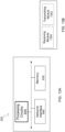
- FIGURE 12B is a block diagram illustrating example components of network node 120.
- the components may include receiving module 1250, determining module 1252, and transmitting module 1254.
- Receiving module 1250 may perform the receiving functions of network node 120. For example, receiving module 1250 may receive, from a core network node, a request to receive a notification of a transition of the UE between a first RRC state and a second RRC state, as described in any of the embodiments or examples above. In certain embodiments, receiving module 1250 may include or be included in processing circuitry 1220. In particular embodiments, receiving module 1250 may communicate with determining module 1252 and transmitting module 1254.
- Determining module 1252 may perform the determining functions of network node 120. For example, determining module 1252 may determine a UE transitioned between a first RRC state and a second RRC state according to any of the examples described above. In certain embodiments, determining module 1252 may include or be included in processing circuitry 1220. In particular embodiments, determining module 1252 may communicate with receiving module 1250 and transmitting module 1254.
- Transmitting module 1254 may perform the transmitting functions of network node 120. For example, transmitting module 1254 may transmit a subscription response and/or a state transition notification to a core network node according to any of the examples described above. In certain embodiments, transmitting module 1254 may include or be included in processing circuitry 1220. In particular embodiments, transmitting module 1254 may communicate with receiving module 1250 and determining module 1252.
- FIGURE 13A is a block schematic of an example core network node 320, in accordance with certain embodiments.
- the core network node is capable of sending, to a network node, a subscription request to receive a notification of a transition of a UE between a first RRC state and a second RRC state; and upon the network node determining the UE transitioned between the first RRC state and the second RRC state, receiving the notification from the network node.
- the core network node may receive, from the network node, a subscription response indicating that the network node will provide the notification.
- Examples of core network nodes can include a mobile switching center (MSC), a serving GPRS support node (SGSN), a mobility management entity (MME), a radio network controller (RNC), a base station controller (BSC), an access and mobility management function (AMF), and so on.
- the core network node includes processing circuitry 620, memory 630, and network interface 640.
- processing circuitry 620 executes instructions to provide some or all of the functionality described above as being provided by the network node
- memory 630 stores the instructions executed by processing circuitry 620
- network interface 640 communicates signals to any suitable node, such as a gateway, switch, router, Internet, Public Switched Telephone Network (PSTN), network nodes 120, radio network controllers or core network nodes 320, etc.
- PSTN Public Switched Telephone Network
- Processing circuitry 620 may include any suitable combination of hardware and software implemented in one or more modules to execute instructions and manipulate data to perform some or all of the described functions of the core network node.
- processing circuitry 620 may include, for example, one or more computers, one or more central processing units (CPUs), one or more microprocessors, one or more applications, and/or other logic.
- Memory 630 is generally operable to store instructions, such as a computer program, software, an application including one or more of logic, rules, algorithms, code, tables, etc. and/or other instructions capable of being executed by a processor.
- Examples of memory 630 include computer memory (for example, Random Access Memory (RAM) or Read Only Memory (ROM)), mass storage media (for example, a hard disk), removable storage media (for example, a Compact Disk (CD) or a Digital Video Disk (DVD)), and/or or any other volatile or non-volatile, non-transitory computer-readable and/or computer-executable memory devices that store information.
- RAM Random Access Memory
- ROM Read Only Memory
- mass storage media for example, a hard disk
- removable storage media for example, a Compact Disk (CD) or a Digital Video Disk (DVD)
- CD Compact Disk
- DVD Digital Video Disk
- network interface 640 is communicatively coupled to processing circuitry 620 and may refer to any suitable device operable to receive input for the network node, send output from the network node, perform suitable processing of the input or output or both, communicate to other devices, or any combination of the preceding.
- Network interface 640 may include appropriate hardware (e.g., port, modem, network interface card, etc.) and software, including protocol conversion and data processing capabilities, to communicate through a network.
- network node may include additional components beyond those shown in FIGURE 6 that may be responsible for providing certain aspects of the network node's functionality, including any of the functionality described above and/or any additional functionality (including any functionality necessary to support the solution described above).
- FIGURE 13B is a block diagram illustrating example components of core network node 320.
- the components may include receiving module 1350 and transmitting module 1352.
- Receiving module 1350 may perform the receiving functions of core network node 320. For example, receiving module 1350 may receive, from a network node, a response to a notification subscription and/or a notification of a transition of a UE between a first RRC state and a second RRC state, as described in any of the embodiments or examples above. In certain embodiments, receiving module 1350 may include or be included in processing circuitry 620. In particular embodiments, receiving module 1350 may communicate with transmitting module 1352.
- Transmitting module 1352 may perform the transmitting functions of core network node 320. For example, transmitting module 1352 may transmit a subscription request to a network node according to any of the examples described above. In certain embodiments, transmitting module 1352 may include or be included in processing circuitry 620. In particular embodiments, transmitting module 1352 may communicate with receiving module 1350.
- Some embodiments of the disclosure may provide one or more technical advantages. Some embodiments may benefit from some, none, or all of these advantages. Other technical advantages may be readily ascertained by one of ordinary skill in the art. For example, some embodiments may advantageously enable the CN to subscribe to certain information available in RAN (e.g., the UE transition between RRC CONNECTED and RRC CONNECTED INACTIVE). The CN can use the information as input to its functions (e.g., based on the reliability of the knowledge about UE's location). As an example, the CN could adjust its behavior for UE location monitoring during periods of inactive connected state when the UE is not connected to the system at AS level and when it would not necessarily report a change of location (e.g., change of cell).
- certain information available in RAN e.g., the UE transition between RRC CONNECTED and RRC CONNECTED INACTIVE.
- the CN can use the information as input to its functions (e.g., based on the reliability of the knowledge about
- any suitable radio access technology such as long term evolution (LTE), LTE-Advanced, NR, UMTS, HSPA, GSM, cdma2000, WiMax, WiFi, etc. Accordingly, the above description of the embodiments does not constrain this disclosure.
Landscapes
- Engineering & Computer Science (AREA)
- Computer Networks & Wireless Communication (AREA)
- Signal Processing (AREA)
- Mobile Radio Communication Systems (AREA)
Claims (11)
- Verfahren (900), durchgeführt von einem Netzwerkknoten zum Bereitstellen eines Funkressourcensteuerungszustands, RRC-Zustands eines Benutzergeräts, UE, an einen Kernnetzwerkknoten, wobei das Verfahren Folgendes umfasst:Empfangen (912), von dem Kernnetzwerkknoten, einer Abonnementanforderung zum Empfangen einer Benachrichtigung zu einem Übergang des UE zwischen einem ersten RRC-Zustand und einem zweiten RRC-Zustand, wobei die Abonnementanforderung eine Periodizität zum Empfangen der Benachrichtigung beinhaltet, wobei die Periodizität vorgibt, ob die Benachrichtigung eine einmalige Benachrichtigung oder eine Benachrichtigung für jeden nachfolgenden Übergang des UE zwischen dem ersten RRC-Zustand und dem zweiten RRC-Zustand ist;Bestimmen (916), dass das UE zwischen dem ersten RRC-Zustand und dem zweiten RRC-Zustand übergegangen ist; undSenden (918) der Benachrichtigung zu dem Übergang des UE zwischen dem ersten RRC-Zustand und dem zweiten RRC-Zustand an den Kernnetzwerkknoten,wobei der erste RRC-Zustand ein RRC-Verbunden-Zustand und der zweite RRC-Zustand ein RRC-Verbunden-Inaktiv-Zustand ist.
- Verfahren (900) nach Anspruch 1, ferner umfassend Senden (914), an den Kernnetzwerkknoten, einer Abonnementantwort, die anzeigt, dass der Netzwerkknoten die Benachrichtigung bereitstellen wird.
- Verfahren (900) nach Anspruch 1 oder 2, wobei die Abonnementanforderung eine Anforderung zum Empfangen von Standortinformationen des UE beinhaltet.
- Verfahren (900) nach einem der Ansprüche 1 bis 3, wobei die Benachrichtigung Standortinformationen des UE beinhaltet.
- Verfahren (900) nach Anspruch 2, wobei die Abonnementanforderung ein Informationselement, IE, in einer ANFANGSKONTEXT-SETUP-ANFORDERUNG umfasst und die Abonnementantwort ein IE in einer ANFANGSKONTEXT-SETUP-ANTWORT umfasst.
- Verfahren (1000), durchgeführt von einem Kernnetzwerkknoten, zum Empfangen von Funkressourcensteuerungszustandsinformationen, RRC-Zustandsinformationen eines Benutzergeräts, UE, von einem Netzwerkknoten, wobei das Verfahren Folgendes umfasst:Senden (1012), an einen Netzwerkknoten, einer Abonnementanforderung zum Empfangen einer Benachrichtigung zu einem Übergang des UE zwischen einem ersten RRC-Zustand und einem zweiten RRC-Zustand, wobei die Abonnementanforderung eine Periodizität zum Empfangen der Benachrichtigung beinhaltet, wobei die Periodizität vorgibt, ob die Benachrichtigung eine einmalige Benachrichtigung oder eine Benachrichtigung für jeden nachfolgenden Übergang des UE zwischen dem ersten RRC-Zustand und dem zweiten RRC-Zustand ist; undnachdem (1016) der Netzwerkknoten bestimmt hat, dass das UE zwischen dem ersten RRC-Zustand und dem zweiten RRC-Zustand übergegangen ist, Empfangen der Benachrichtigung von dem Netzwerkknoten,wobei der erste RRC-Zustand ein RRC-Verbunden-Zustand und der zweite RRC-Zustand ein RRC-Verbunden-Inaktiv-Zustand ist.
- Verfahren (1000) nach Anspruch 6, ferner umfassend Empfangen (1014), von dem Netzwerkknoten, einer Abonnementantwort, die anzeigt, dass der Netzwerkknoten die Benachrichtigung bereitstellen wird.
- Verfahren (1000) nach einem der Ansprüche 6 und 7, wobei die Abonnementanforderung eine Anforderung zum Empfangen von Standortinformationen des UE beinhaltet.
- Verfahren (1000) nach einem der Ansprüche 6 bis 8, wobei die Benachrichtigung Standortinformationen des UE beinhaltet.
- Verfahren (1000) nach Anspruch 7, wobei die Abonnementanforderung ein Informationselement, IE, in einer ANFANGSKONTEXT-SETUP-ANFORDERUNG umfasst und die Abonnementantwort ein IE in einer ANFANGSKONTEXT-SETUP-ANTWORT umfasst.
- Verfahren (1000) nach einem der Ansprüche 6 bis 10, ferner umfassend Modifizieren (1018) eines Betriebs des Kernnetzwerkknotens in Bezug auf das UE basierend auf der empfangenen Benachrichtigung.
Applications Claiming Priority (3)
| Application Number | Priority Date | Filing Date | Title |
|---|---|---|---|
| US201662402073P | 2016-09-30 | 2016-09-30 | |
| EP17794062.4A EP3520559B1 (de) | 2016-09-30 | 2017-09-29 | Kernnetzwerkbewusstsein eines benutzergeräts rrc status |
| PCT/IB2017/056040 WO2018060968A1 (en) | 2016-09-30 | 2017-09-29 | Core network awareness of user equipment, ue, state |
Related Parent Applications (2)
| Application Number | Title | Priority Date | Filing Date |
|---|---|---|---|
| EP17794062.4A Division EP3520559B1 (de) | 2016-09-30 | 2017-09-29 | Kernnetzwerkbewusstsein eines benutzergeräts rrc status |
| EP17794062.4A Division-Into EP3520559B1 (de) | 2016-09-30 | 2017-09-29 | Kernnetzwerkbewusstsein eines benutzergeräts rrc status |
Publications (4)
| Publication Number | Publication Date |
|---|---|
| EP4243563A2 EP4243563A2 (de) | 2023-09-13 |
| EP4243563A3 EP4243563A3 (de) | 2023-12-06 |
| EP4243563B1 true EP4243563B1 (de) | 2024-11-20 |
| EP4243563C0 EP4243563C0 (de) | 2024-11-20 |
Family
ID=60245138
Family Applications (2)
| Application Number | Title | Priority Date | Filing Date |
|---|---|---|---|
| EP23188744.9A Active EP4243563B1 (de) | 2016-09-30 | 2017-09-29 | Kernnetzwerkbewusstsein eines benutzergerät-rrc-zustands |
| EP17794062.4A Active EP3520559B1 (de) | 2016-09-30 | 2017-09-29 | Kernnetzwerkbewusstsein eines benutzergeräts rrc status |
Family Applications After (1)
| Application Number | Title | Priority Date | Filing Date |
|---|---|---|---|
| EP17794062.4A Active EP3520559B1 (de) | 2016-09-30 | 2017-09-29 | Kernnetzwerkbewusstsein eines benutzergeräts rrc status |
Country Status (10)
| Country | Link |
|---|---|
| US (3) | US10880948B2 (de) |
| EP (2) | EP4243563B1 (de) |
| JP (1) | JP6817424B2 (de) |
| CN (2) | CN116406029B (de) |
| CA (1) | CA3037476C (de) |
| ES (2) | ES2965202T3 (de) |
| MX (1) | MX2019003657A (de) |
| PL (1) | PL3520559T3 (de) |
| RU (1) | RU2727163C1 (de) |
| WO (1) | WO2018060968A1 (de) |
Families Citing this family (24)
| Publication number | Priority date | Publication date | Assignee | Title |
|---|---|---|---|---|
| EP4243563B1 (de) * | 2016-09-30 | 2024-11-20 | Telefonaktiebolaget LM Ericsson (publ) | Kernnetzwerkbewusstsein eines benutzergerät-rrc-zustands |
| JP6686234B2 (ja) * | 2016-11-03 | 2020-04-22 | エルジー エレクトロニクス インコーポレイティド | 無線通信システムにおけるngsからepsへの移動方法及びそのための装置 |
| WO2018086059A1 (en) * | 2016-11-11 | 2018-05-17 | Qualcomm Incorporated | Access control in connected mode, idle mode, and inactive state |
| CN109863785A (zh) * | 2016-12-23 | 2019-06-07 | 富士通株式会社 | 数据发送/接收装置、方法以及通信系统 |
| US11432361B2 (en) * | 2016-12-26 | 2022-08-30 | Beijing Xiaomi Mobile Software Co., Ltd. | Method and apparatus for configuring UE information, base station and core network device |
| RU2725166C1 (ru) * | 2017-03-13 | 2020-06-30 | ЭлДжи ЭЛЕКТРОНИКС ИНК. | Способ для приема отчета, сетевое устройство, способ для предоставления отчета и базовая станция |
| CN109547932B (zh) * | 2017-08-15 | 2023-05-16 | 华为技术有限公司 | 一种通信方法及装置 |
| CN110431913B (zh) * | 2017-09-21 | 2022-02-25 | 华为技术有限公司 | 连接管理方法、用户设备、核心网实体及系统 |
| EP3695684B1 (de) | 2017-10-13 | 2021-03-10 | Telefonaktiebolaget LM Ericsson (Publ) | Verbesserte n2 benachrichtigungsprozedur |
| CN111183678A (zh) * | 2018-01-11 | 2020-05-19 | Oppo广东移动通信有限公司 | 基于业务进行处理的方法、终端设备及网络设备 |
| EP3791626A1 (de) * | 2018-05-10 | 2021-03-17 | Nokia Technologies Oy | Bewahrung der auswahl eines funknetzsystems |
| WO2020139178A1 (en) * | 2018-12-28 | 2020-07-02 | Telefonaktiebolaget Lm Ericsson (Publ) | Apparatuses and methods for dual connectivity |
| CN111278088B (zh) * | 2019-01-04 | 2022-02-01 | 维沃移动通信有限公司 | 定位方法及终端 |
| CN111757317B (zh) * | 2019-03-28 | 2021-12-28 | 上海华为技术有限公司 | 一种请求处理方法、相关装置及系统 |
| WO2020221464A1 (en) * | 2019-05-02 | 2020-11-05 | Nokia Technologies Oy | Distinction of minimization drive test logging through different radio resource controller states |
| WO2021130409A1 (en) * | 2019-12-23 | 2021-07-01 | Nokia Technologies Oy | Method, apparatus, and computer program product for alternative quality of service profile notification handling |
| WO2021127973A1 (en) | 2019-12-24 | 2021-07-01 | Nokia Shanghai Bell Co., Ltd. | Caching configuration profiles associated with capability id |
| CN115152253B (zh) * | 2020-01-03 | 2024-03-15 | 索尼集团公司 | 数据链路上的动态状态信息的报告服务 |
| US11265786B2 (en) * | 2020-02-11 | 2022-03-01 | Netscout Systems, Inc | Radio access network service mediated enhanced session records for artificial intelligence or machine learning |
| CN111800311B (zh) * | 2020-06-22 | 2021-10-08 | 中科边缘智慧信息科技(苏州)有限公司 | 分散计算状态实时感知方法 |
| BR102021016648A2 (pt) * | 2020-08-26 | 2022-03-08 | Nokia Technologies Oy | Realocação de contexto de equipamento de usuário na borda de área de notificação de rede de acesso de rádio |
| US20260101261A1 (en) * | 2022-09-29 | 2026-04-09 | Lg Electronics Inc. | Security handling for subsequent mobility |
| US12477499B2 (en) * | 2022-10-14 | 2025-11-18 | Verizon Patent And Licensing Inc. | Systems and methods for analytics and information sharing between a radio access network and a core network |
| KR20250091582A (ko) * | 2023-12-14 | 2025-06-23 | 삼성전자주식회사 | 이동 통신 시스템에서 비동기식 단말 서비스의 관리 방법 및 장치 |
Family Cites Families (36)
| Publication number | Priority date | Publication date | Assignee | Title |
|---|---|---|---|---|
| EP1357754A1 (de) * | 2002-04-23 | 2003-10-29 | Canal + Technologies | Chatsystem über Fernsehnetzwerken |
| WO2008147046A1 (en) * | 2007-05-25 | 2008-12-04 | Lg Electronics Inc. | Management procedure in wireless communication system and station supporting management procedure |
| US9839001B2 (en) | 2009-03-23 | 2017-12-05 | Apple Inc. | Methods and apparatus for optimizing paging mechanisms and publication of dynamic paging mechanisms |
| BR112012012356B1 (pt) * | 2009-11-23 | 2021-05-04 | Blackberry Limited | métodos e equipamentos de usuário para processamento de mensagens de indicação |
| JP5654618B2 (ja) * | 2010-02-12 | 2015-01-14 | インターデイジタル パテント ホールディングス インコーポレイテッド | マシンタイプ通信をサポートする方法および装置 |
| CN103748810B (zh) | 2011-08-11 | 2017-05-10 | 英特尔公司 | 用于dash格式化内容从mbms下载切换到基于http的交付的方法和设备 |
| US9832672B2 (en) | 2012-04-27 | 2017-11-28 | Mitsubishi Electric Corporation | Communication system |
| WO2014031713A1 (en) * | 2012-08-21 | 2014-02-27 | Interdigital Patent Holdings, Inc. | Enhanced higher layer discovery methods for proximity services |
| EP2753133B1 (de) * | 2013-01-08 | 2016-04-06 | HTC Corporation | Verfahren zur Handhabung von Proximitätsdienst in einem drahtlosen Kommunikationssystem |
| JP2014143616A (ja) * | 2013-01-24 | 2014-08-07 | Ntt Docomo Inc | ユーザ装置、ゲートウェイ装置、無線基地局、移動通信システム及び移動通信方法 |
| WO2014166071A1 (zh) * | 2013-04-09 | 2014-10-16 | 华为技术有限公司 | 数据传输方法、装置及系统 |
| US9661657B2 (en) * | 2013-11-27 | 2017-05-23 | Intel Corporation | TCP traffic adaptation in wireless systems |
| EP3078236A1 (de) | 2013-12-06 | 2016-10-12 | Interdigital Patent Holdings, Inc. | Geschichtete konnektivität in drahtlosen systemen |
| KR20150073825A (ko) * | 2013-12-20 | 2015-07-01 | 삼성전자주식회사 | 이동 통신 시스템에서 음성 호 설정 시간을 단축시키는 방법 및 장치 |
| KR102321203B1 (ko) * | 2014-05-08 | 2021-11-04 | 인터디지탈 패튼 홀딩스, 인크 | Ue를 전용 코어 네트워크 노드에 리디렉트하기 위한 방법들 및 이동성 관리 엔티티(mme) |
| JP6510038B2 (ja) * | 2014-09-29 | 2019-05-08 | コンヴィーダ ワイヤレス, エルエルシー | 電力節約モードおよびページングのためのサービス能力サーバ/epc調整 |
| WO2016089349A1 (en) | 2014-12-01 | 2016-06-09 | Nokia Solutions And Networks Oy | Inactive communication mode |
| EP4236496A3 (de) * | 2014-12-23 | 2023-10-11 | InterDigital Patent Holdings, Inc. | Latenzverringerung in lte-systemen |
| US10667321B2 (en) | 2015-02-09 | 2020-05-26 | Intel IP Corporation | Evolved Node-B, user equipment, and methods for transition between idle and connected modes |
| EP3400731B1 (de) * | 2016-01-08 | 2019-09-25 | Telefonaktiebolaget LM Ericsson (PUBL) | Zugangskontrolle in einem netzwerk mit netzwerkteilen |
| WO2017126928A1 (ko) * | 2016-01-20 | 2017-07-27 | 엘지전자 주식회사 | 연결 모드 변경 방법 및 이동성 관리 개체 |
| EP3417648B1 (de) * | 2016-02-15 | 2019-11-27 | Telefonaktiebolaget LM Ericsson (publ) | Netzwerkknoten und darin ausgeführte verfahren zur ermöglichung der kommunikation in einem kommunikationsnetzwerk |
| WO2017140341A1 (en) * | 2016-02-15 | 2017-08-24 | Telefonaktiebolaget Lm Ericsson (Publ) | Network nodes and methods performed therein for enabling communication in a communication network |
| WO2017196146A1 (ko) * | 2016-05-12 | 2017-11-16 | 삼성전자 주식회사 | 단말의 전력을 절약하기 위한 방법 및 장치 |
| EP3484232A4 (de) * | 2016-08-10 | 2019-05-15 | Kyocera Corporation | Basisstation und mobilitätsverwaltungseinheit |
| US10917786B2 (en) * | 2016-08-11 | 2021-02-09 | Samsung Electronics Co., Ltd. | Low power RRC operating method and device |
| US20190239191A1 (en) * | 2016-08-19 | 2019-08-01 | Telefonaktiebolaget Lm Ericsson (Publ) | Radio access network node and a core network node for paging a wireless device in a wireless communication network |
| WO2018056347A1 (ja) * | 2016-09-21 | 2018-03-29 | 京セラ株式会社 | 基地局及び無線端末 |
| BR112019001471A2 (pt) * | 2016-09-28 | 2019-05-07 | Sony Corporation | unidade de transmissão/recepção sem fio, e, método de transmissão de dados |
| KR20180035638A (ko) * | 2016-09-29 | 2018-04-06 | 삼성전자주식회사 | RRC Inactive 및 active 상태에서 data 전송 결정 및 방법 및 장치 |
| US10356837B2 (en) * | 2016-09-29 | 2019-07-16 | Acer Incorporated | State transitioning method and electronic device using the same |
| CN113727327A (zh) * | 2016-09-29 | 2021-11-30 | 华为技术有限公司 | 一种通信方法、设备和系统 |
| EP4243563B1 (de) * | 2016-09-30 | 2024-11-20 | Telefonaktiebolaget LM Ericsson (publ) | Kernnetzwerkbewusstsein eines benutzergerät-rrc-zustands |
| US10952107B2 (en) * | 2016-09-30 | 2021-03-16 | Lg Electronics Inc. | Method for performing RRC connection reestablishment process and apparatus supporting same |
| KR102165255B1 (ko) * | 2017-02-06 | 2020-10-13 | 삼성전자 주식회사 | non-3gpp를 통해 5G네트워크에 접속하는 단말에 대한 registration 관리 방안 |
| US10237681B2 (en) | 2017-02-06 | 2019-03-19 | Samsung Electronics Co., Ltd. | Registration management method for terminal accessing 5G network on non-3GPP access |
-
2017
- 2017-09-29 EP EP23188744.9A patent/EP4243563B1/de active Active
- 2017-09-29 ES ES17794062T patent/ES2965202T3/es active Active
- 2017-09-29 JP JP2019517336A patent/JP6817424B2/ja active Active
- 2017-09-29 US US16/338,021 patent/US10880948B2/en active Active
- 2017-09-29 MX MX2019003657A patent/MX2019003657A/es unknown
- 2017-09-29 CN CN202310348160.4A patent/CN116406029B/zh active Active
- 2017-09-29 PL PL17794062.4T patent/PL3520559T3/pl unknown
- 2017-09-29 EP EP17794062.4A patent/EP3520559B1/de active Active
- 2017-09-29 ES ES23188744T patent/ES2995258T3/es active Active
- 2017-09-29 CA CA3037476A patent/CA3037476C/en active Active
- 2017-09-29 RU RU2019112884A patent/RU2727163C1/ru active
- 2017-09-29 WO PCT/IB2017/056040 patent/WO2018060968A1/en not_active Ceased
- 2017-09-29 CN CN201780074197.5A patent/CN109997408B/zh active Active
-
2020
- 2020-12-04 US US17/112,632 patent/US11464067B2/en active Active
-
2022
- 2022-10-03 US US17/937,570 patent/US20230047656A1/en not_active Abandoned
Also Published As
| Publication number | Publication date |
|---|---|
| EP4243563A3 (de) | 2023-12-06 |
| CN109997408A (zh) | 2019-07-09 |
| CA3037476A1 (en) | 2018-04-05 |
| US10880948B2 (en) | 2020-12-29 |
| US20190246445A1 (en) | 2019-08-08 |
| CN116406029B (zh) | 2025-09-23 |
| MX2019003657A (es) | 2019-08-05 |
| CA3037476C (en) | 2023-05-23 |
| RU2727163C1 (ru) | 2020-07-21 |
| US11464067B2 (en) | 2022-10-04 |
| JP2019533933A (ja) | 2019-11-21 |
| EP4243563C0 (de) | 2024-11-20 |
| EP4243563A2 (de) | 2023-09-13 |
| EP3520559A1 (de) | 2019-08-07 |
| CN109997408B (zh) | 2023-04-25 |
| US20230047656A1 (en) | 2023-02-16 |
| ES2965202T3 (es) | 2024-04-11 |
| CN116406029A (zh) | 2023-07-07 |
| JP6817424B2 (ja) | 2021-01-20 |
| PL3520559T3 (pl) | 2024-03-04 |
| EP3520559B1 (de) | 2023-09-20 |
| ES2995258T3 (en) | 2025-02-10 |
| WO2018060968A1 (en) | 2018-04-05 |
| US20210092793A1 (en) | 2021-03-25 |
Similar Documents
| Publication | Publication Date | Title |
|---|---|---|
| US11464067B2 (en) | Core network awareness of user equipment, UE, state | |
| US20240205667A1 (en) | Storage of ue contexts in ran for inactive ues | |
| US10681767B2 (en) | Method and apparatus for performing RRC connection resume in wireless communication system | |
| US10582522B2 (en) | Data transmission and reception method and device of terminal in wireless communication system | |
| KR20190020142A (ko) | 무선 통신 시스템에서 네트워크간 상호연동 방법 및 이를 위한 장치 | |
| KR20190117653A (ko) | 통신 방법 및 기기 | |
| US10623990B2 (en) | User equipment and method for transmitting data, and network node and method for receiving data | |
| US20200267800A1 (en) | Method for performing s1 connection release by mobility management object, mobility management object, method for performing s1 connection release by base station, and base station | |
| EP3410814B1 (de) | Verfahren zum beginn von verfolgungsbereichsaktualisierung und benutzergerät | |
| AU2018236614A1 (en) | Method for receiving report, network device, method for performing report, and base station | |
| US20240406846A1 (en) | Managing ue measurements in an idle or inactive state | |
| HK40011669B (en) | Core network awareness of user equipment, ue, state | |
| HK40011669A (en) | Core network awareness of user equipment, ue, state |
Legal Events
| Date | Code | Title | Description |
|---|---|---|---|
| PUAI | Public reference made under article 153(3) epc to a published international application that has entered the european phase |
Free format text: ORIGINAL CODE: 0009012 |
|
| STAA | Information on the status of an ep patent application or granted ep patent |
Free format text: STATUS: THE APPLICATION HAS BEEN PUBLISHED |
|
| AC | Divisional application: reference to earlier application |
Ref document number: 3520559 Country of ref document: EP Kind code of ref document: P |
|
| AK | Designated contracting states |
Kind code of ref document: A2 Designated state(s): AL AT BE BG CH CY CZ DE DK EE ES FI FR GB GR HR HU IE IS IT LI LT LU LV MC MK MT NL NO PL PT RO RS SE SI SK SM TR |
|
| REG | Reference to a national code |
Ref country code: DE Ref legal event code: R079 Free format text: PREVIOUS MAIN CLASS: H04W0076280000 Ipc: H04W0076270000 Ref country code: DE Ref legal event code: R079 Ref document number: 602017086337 Country of ref document: DE Free format text: PREVIOUS MAIN CLASS: H04W0076280000 Ipc: H04W0076270000 |
|
| PUAL | Search report despatched |
Free format text: ORIGINAL CODE: 0009013 |
|
| AK | Designated contracting states |
Kind code of ref document: A3 Designated state(s): AL AT BE BG CH CY CZ DE DK EE ES FI FR GB GR HR HU IE IS IT LI LT LU LV MC MK MT NL NO PL PT RO RS SE SI SK SM TR |
|
| RIC1 | Information provided on ipc code assigned before grant |
Ipc: H04W 76/27 20180101AFI20231102BHEP |
|
| STAA | Information on the status of an ep patent application or granted ep patent |
Free format text: STATUS: REQUEST FOR EXAMINATION WAS MADE |
|
| 17P | Request for examination filed |
Effective date: 20240606 |
|
| RBV | Designated contracting states (corrected) |
Designated state(s): AL AT BE BG CH CY CZ DE DK EE ES FI FR GB GR HR HU IE IS IT LI LT LU LV MC MK MT NL NO PL PT RO RS SE SI SK SM TR |
|
| GRAP | Despatch of communication of intention to grant a patent |
Free format text: ORIGINAL CODE: EPIDOSNIGR1 |
|
| STAA | Information on the status of an ep patent application or granted ep patent |
Free format text: STATUS: GRANT OF PATENT IS INTENDED |
|
| INTG | Intention to grant announced |
Effective date: 20240718 |
|
| RIN1 | Information on inventor provided before grant (corrected) |
Inventor name: SCHLIWA-BERTLING, PAUL Inventor name: OLSSON, LASSE Inventor name: MILDH, GUNNAR Inventor name: CENTONZA, ANGELO |
|
| GRAS | Grant fee paid |
Free format text: ORIGINAL CODE: EPIDOSNIGR3 |
|
| GRAA | (expected) grant |
Free format text: ORIGINAL CODE: 0009210 |
|
| STAA | Information on the status of an ep patent application or granted ep patent |
Free format text: STATUS: THE PATENT HAS BEEN GRANTED |
|
| AC | Divisional application: reference to earlier application |
Ref document number: 3520559 Country of ref document: EP Kind code of ref document: P |
|
| AK | Designated contracting states |
Kind code of ref document: B1 Designated state(s): AL AT BE BG CH CY CZ DE DK EE ES FI FR GB GR HR HU IE IS IT LI LT LU LV MC MK MT NL NO PL PT RO RS SE SI SK SM TR |
|
| REG | Reference to a national code |
Ref country code: GB Ref legal event code: FG4D |
|
| REG | Reference to a national code |
Ref country code: CH Ref legal event code: EP |
|
| REG | Reference to a national code |
Ref country code: DE Ref legal event code: R096 Ref document number: 602017086337 Country of ref document: DE |
|
| REG | Reference to a national code |
Ref country code: IE Ref legal event code: FG4D |
|
| U01 | Request for unitary effect filed |
Effective date: 20241204 |
|
| U07 | Unitary effect registered |
Designated state(s): AT BE BG DE DK EE FI FR IT LT LU LV MT NL PT RO SE SI Effective date: 20241213 |
|
| REG | Reference to a national code |
Ref country code: ES Ref legal event code: FG2A Ref document number: 2995258 Country of ref document: ES Kind code of ref document: T3 Effective date: 20250210 |
|
| PG25 | Lapsed in a contracting state [announced via postgrant information from national office to epo] |
Ref country code: HR Free format text: LAPSE BECAUSE OF FAILURE TO SUBMIT A TRANSLATION OF THE DESCRIPTION OR TO PAY THE FEE WITHIN THE PRESCRIBED TIME-LIMIT Effective date: 20241120 Ref country code: IS Free format text: LAPSE BECAUSE OF FAILURE TO SUBMIT A TRANSLATION OF THE DESCRIPTION OR TO PAY THE FEE WITHIN THE PRESCRIBED TIME-LIMIT Effective date: 20250320 |
|
| PG25 | Lapsed in a contracting state [announced via postgrant information from national office to epo] |
Ref country code: NO Free format text: LAPSE BECAUSE OF FAILURE TO SUBMIT A TRANSLATION OF THE DESCRIPTION OR TO PAY THE FEE WITHIN THE PRESCRIBED TIME-LIMIT Effective date: 20250220 |
|
| PG25 | Lapsed in a contracting state [announced via postgrant information from national office to epo] |
Ref country code: GR Free format text: LAPSE BECAUSE OF FAILURE TO SUBMIT A TRANSLATION OF THE DESCRIPTION OR TO PAY THE FEE WITHIN THE PRESCRIBED TIME-LIMIT Effective date: 20250221 |
|
| PG25 | Lapsed in a contracting state [announced via postgrant information from national office to epo] |
Ref country code: PL Free format text: LAPSE BECAUSE OF FAILURE TO SUBMIT A TRANSLATION OF THE DESCRIPTION OR TO PAY THE FEE WITHIN THE PRESCRIBED TIME-LIMIT Effective date: 20241120 |
|
| PG25 | Lapsed in a contracting state [announced via postgrant information from national office to epo] |
Ref country code: RS Free format text: LAPSE BECAUSE OF FAILURE TO SUBMIT A TRANSLATION OF THE DESCRIPTION OR TO PAY THE FEE WITHIN THE PRESCRIBED TIME-LIMIT Effective date: 20250220 |
|
| PG25 | Lapsed in a contracting state [announced via postgrant information from national office to epo] |
Ref country code: SM Free format text: LAPSE BECAUSE OF FAILURE TO SUBMIT A TRANSLATION OF THE DESCRIPTION OR TO PAY THE FEE WITHIN THE PRESCRIBED TIME-LIMIT Effective date: 20241120 |
|
| PG25 | Lapsed in a contracting state [announced via postgrant information from national office to epo] |
Ref country code: SK Free format text: LAPSE BECAUSE OF FAILURE TO SUBMIT A TRANSLATION OF THE DESCRIPTION OR TO PAY THE FEE WITHIN THE PRESCRIBED TIME-LIMIT Effective date: 20241120 |
|
| PG25 | Lapsed in a contracting state [announced via postgrant information from national office to epo] |
Ref country code: CZ Free format text: LAPSE BECAUSE OF FAILURE TO SUBMIT A TRANSLATION OF THE DESCRIPTION OR TO PAY THE FEE WITHIN THE PRESCRIBED TIME-LIMIT Effective date: 20241120 |
|
| PLBE | No opposition filed within time limit |
Free format text: ORIGINAL CODE: 0009261 |
|
| STAA | Information on the status of an ep patent application or granted ep patent |
Free format text: STATUS: NO OPPOSITION FILED WITHIN TIME LIMIT |
|
| PGFP | Annual fee paid to national office [announced via postgrant information from national office to epo] |
Ref country code: GB Payment date: 20250929 Year of fee payment: 9 |
|
| 26N | No opposition filed |
Effective date: 20250821 |
|
| U20 | Renewal fee for the european patent with unitary effect paid |
Year of fee payment: 9 Effective date: 20250929 |
|
| PGFP | Annual fee paid to national office [announced via postgrant information from national office to epo] |
Ref country code: ES Payment date: 20251001 Year of fee payment: 9 |
|
| REG | Reference to a national code |
Ref country code: CH Ref legal event code: H13 Free format text: ST27 STATUS EVENT CODE: U-0-0-H10-H13 (AS PROVIDED BY THE NATIONAL OFFICE) Effective date: 20260425 |