EP4243522B1 - Relaxation von ue-messungen - Google Patents
Relaxation von ue-messungen Download PDFInfo
- Publication number
- EP4243522B1 EP4243522B1 EP23159531.5A EP23159531A EP4243522B1 EP 4243522 B1 EP4243522 B1 EP 4243522B1 EP 23159531 A EP23159531 A EP 23159531A EP 4243522 B1 EP4243522 B1 EP 4243522B1
- Authority
- EP
- European Patent Office
- Prior art keywords
- distance
- terminal device
- access node
- time interval
- mobile terminal
- Prior art date
- Legal status (The legal status is an assumption and is not a legal conclusion. Google has not performed a legal analysis and makes no representation as to the accuracy of the status listed.)
- Active
Links
Images


Classifications
-
- H—ELECTRICITY
- H04—ELECTRIC COMMUNICATION TECHNIQUE
- H04W—WIRELESS COMMUNICATION NETWORKS
- H04W24/00—Supervisory, monitoring or testing arrangements
- H04W24/08—Testing, supervising or monitoring using real traffic
-
- H—ELECTRICITY
- H04—ELECTRIC COMMUNICATION TECHNIQUE
- H04W—WIRELESS COMMUNICATION NETWORKS
- H04W64/00—Locating users or terminals or network equipment for network management purposes, e.g. mobility management
-
- H—ELECTRICITY
- H04—ELECTRIC COMMUNICATION TECHNIQUE
- H04W—WIRELESS COMMUNICATION NETWORKS
- H04W64/00—Locating users or terminals or network equipment for network management purposes, e.g. mobility management
- H04W64/006—Locating users or terminals or network equipment for network management purposes, e.g. mobility management with additional information processing, e.g. for direction or speed determination
-
- G—PHYSICS
- G01—MEASURING; TESTING
- G01S—RADIO DIRECTION-FINDING; RADIO NAVIGATION; DETERMINING DISTANCE OR VELOCITY BY USE OF RADIO WAVES; LOCATING OR PRESENCE-DETECTING BY USE OF THE REFLECTION OR RERADIATION OF RADIO WAVES; ANALOGOUS ARRANGEMENTS USING OTHER WAVES
- G01S5/00—Position-fixing by co-ordinating two or more direction or position line determinations; Position-fixing by co-ordinating two or more distance determinations
- G01S5/02—Position-fixing by co-ordinating two or more direction or position line determinations; Position-fixing by co-ordinating two or more distance determinations using radio waves
- G01S5/0294—Trajectory determination or predictive filtering, e.g. target tracking or Kalman filtering
-
- H—ELECTRICITY
- H04—ELECTRIC COMMUNICATION TECHNIQUE
- H04W—WIRELESS COMMUNICATION NETWORKS
- H04W24/00—Supervisory, monitoring or testing arrangements
- H04W24/10—Scheduling measurement reports ; Arrangements for measurement reports
-
- H—ELECTRICITY
- H04—ELECTRIC COMMUNICATION TECHNIQUE
- H04W—WIRELESS COMMUNICATION NETWORKS
- H04W8/00—Network data management
- H04W8/02—Processing of mobility data, e.g. registration information at HLR [Home Location Register] or VLR [Visitor Location Register]; Transfer of mobility data, e.g. between HLR, VLR or external networks
-
- G—PHYSICS
- G01—MEASURING; TESTING
- G01S—RADIO DIRECTION-FINDING; RADIO NAVIGATION; DETERMINING DISTANCE OR VELOCITY BY USE OF RADIO WAVES; LOCATING OR PRESENCE-DETECTING BY USE OF THE REFLECTION OR RERADIATION OF RADIO WAVES; ANALOGOUS ARRANGEMENTS USING OTHER WAVES
- G01S5/00—Position-fixing by co-ordinating two or more direction or position line determinations; Position-fixing by co-ordinating two or more distance determinations
- G01S5/02—Position-fixing by co-ordinating two or more direction or position line determinations; Position-fixing by co-ordinating two or more distance determinations using radio waves
- G01S5/12—Position-fixing by co-ordinating two or more direction or position line determinations; Position-fixing by co-ordinating two or more distance determinations using radio waves by co-ordinating position lines of different shape, e.g. hyperbolic, circular, elliptical or radial
Definitions
- Various embodiments described herein relate to the field of wireless communications and, particularly, to radio resource management measurements performed by a terminal device of a cellular communication system.
- a terminal device of a cellular communication system performs various radio resource management measurements. Some of such measurements include neighbour cell measurements in which the terminal device measures signals received from neighbouring cells for the purpose of a handover. Performing such measurements consumes power in the terminal device.
- US2021105643A1 discloses a method for performing frequency measurement by a terminal in a wireless communication system.
- CN113473556A discusses network deployment, propagation environment, UE mobility direction, UE speed, and UE location.
- an apparatus comprising at least one processor; and at least one memory configured to store instructions that cause the at least one processor to perform at least the following: determining, on the basis of measurement data, a distance between a mobile access node and a mobile terminal device and angular movement of the terminal device with respect to the access node; making a decision about a length of a time interval between consecutive radio measurements of the terminal device on the basis of the distance and the angular movement; and communicating the decision over the radio link or another radio link and causing the terminal device to conduct the consecutive radio measurements with the length of the time interval.
- the angular movement is determined by measuring an angle-of-arrival of a received reference signal in different measuring occasions with respect to a reference axis. Said determination, storing, estimation, decision making and communicating are performed by the mobile access node or by the mobile terminal device; or said determination is performed by the mobile terminal device, and said storing, estimation, decision making and communicating are performed by the mobile access node.
- the time interval indicates duration to the next radio measurement instant.
- the apparatus is configured select a first time interval upon detecting that the distance is decreasing or maintaining, and to select a second time interval shorter than the first time interval upon detecting that the distance is increasing.
- the apparatus is configured to compute at least the second time interval on the basis of a degree of said angular motion.
- the apparatus is configured to store information indicating a cell edge in terms of a distance to the access node, to use the distance and angular motion indicated by the measurement data to estimate a duration until the terminal device reaches the cell edge, and to select the time interval on the basis of the estimated duration.
- the time interval is shorter than the estimated duration.
- the apparatus is configured to: determine whether the distance is increasing or decreasing; if the distance is determined to be increasing, use the distance and the angular motion to determine the time interval; if the distance is determined to be decreasing, determining the time interval on the basis of the distance without the angular motion.
- the apparatus is configured to perform the following, if the distance is determined to be increasing: if the distance is determined to be increasing but at a speed lower than a determined threshold and if the angular motion is determined to be non-zero, computing the time interval on the basis of a distance to an edge of a cell provided by the access node and the threshold; and if the distance is determined to be increasing at a speed greater than the threshold, computing the time interval on the basis of the distance to the cell edge, the speed, and the angular motion.
- a method comprising: determining, on the basis of measurement data measured from a radio link, a distance between a mobile access node and a mobile terminal device and angular movement of the terminal device with respect to the access node; making a decision about a length of a time interval between consecutive radio measurements of the terminal device on the basis of the distance and the angular movement; and communicating the decision over the radio link or another radio link and causing the terminal device to conduct the consecutive radio measurements with the length of the time interval.
- the angular movement is determined by measuring an angle-of-arrival of a received reference signal in different measuring occasions with respect to a reference axis. Said method is performed by the mobile access node or by the mobile terminal device; or said determination is performed by the mobile terminal device, and said storing, estimation, decision making and communicating are performed by the mobile access node.
- the time interval indicates duration to the next radio measurement instant.
- a first time interval is selected upon detecting that the distance is decreasing or maintaining, and a second time interval shorter than the first time interval is selected upon detecting that the distance is increasing.
- the method further comprises storing information indicating a cell edge in terms of a distance to the access node, using the distance and angular motion indicated by the measurement data to estimate a duration until the terminal device reaches the cell edge, and selecting the time interval on the basis of the estimated duration.
- the method further comprises: determining whether the distance is increasing or decreasing; if the distance is determined to be increasing, using the distance and the angular motion to determine the time interval; if the distance is determined to be decreasing, determining the time interval on the basis of the distance without the angular motion.
- the method comprises determining, on the basis of the measurement data, whether or not there is a line-of-sight between the terminal device and the access node and, upon determining that there is no line-of-sight, to average the distance and the angular motion over a measurement window.
- the method further comprises storing information indicating a cell edge in terms of a distance to the access node, using the distance and angular motion indicated by the measurement data to estimate a duration until the terminal device reaches the cell edge, and selecting the time interval on the basis of the estimated duration.
- the method is performed by the terminal device, and wherein said communicating comprises the terminal device transmitting the time interval to the access node.
- the method is performed by the access node, and wherein the access node configures the terminal device to conduct the measurements by transmitting the time interval to the terminal device.
- a computer program product embodied on a computer-readable medium and comprising a computer program code readable by a computer, wherein the computer program code configures the computer to carry out a computer process comprising: determining, on the basis of measurement data measured from a radio link, a distance between a mobile access node and a mobile terminal device and angular movement of the terminal device with respect to the access node; making a decision about a length of a time interval between consecutive radio measurements of the terminal device on the basis of the distance and the angular movement; and communicating the decision over the radio link or another radio link and causing the terminal device to conduct the consecutive radio measurements with the length of the time interval.
- the angular movement is determined by measuring an angle-of-arrival of a received reference signal in different measuring occasions with respect to a reference axis. Said determination, storing, estimation, decision making and communicating are performed by the mobile access node or by the mobile terminal device; or said determination is performed by the mobile terminal device, and said storing, estimation, decision making and communicating are performed by the mobile access node.
- UMTS universal mobile telecommunications system
- UTRAN radio access network
- LTE long term evolution
- WLAN wireless local area network
- WiFi worldwide interoperability for microwave access
- Bluetooth ® personal communications services
- PCS personal communications services
- WCDMA wideband code division multiple access
- UWB ultra-wideband
- IMS Internet Protocol multimedia subsystems
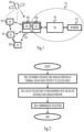
- Figure 1 depicts examples of simplified system architectures only showing some elements and functional entities, all being logical units, whose implementation may differ from what is shown.
- the connections shown in Figure 1 are logical connections; the actual physical connections may be different. It is apparent to a person skilled in the art that the system typically comprises also other functions and structures than those shown in Figure 1 .
- Figure 1 shows a part of an exemplifying radio access network.
- Figure 1 shows terminal devices or user devices 100 and 102 configured to be in a wireless connection on one or more communication channels in a cell with an access node (such as (e/g)NodeB) 104 providing the cell.
- (e/g)NodeB refers to an eNodeB or a gNodeB, as defined in 3GPP specifications.
- the physical link from a user device to a (e/g)NodeB is called uplink or reverse link and the physical link from the (e/g)NodeB to the user device is called downlink or forward link.
- (e/g)NodeBs or their functionalities may be implemented by using any node, host, server or access point etc. entity suitable for such a usage.
- a communications system typically comprises more than one (e/g)NodeB in which case the (e/g)NodeBs may also be configured to communicate with one another over links, wired or wireless, designed for the purpose. These links may be used not only for signalling purposes but also for routing data from one (e/g)NodeB to another.
- the (e/g)NodeB is a computing device configured to control the radio resources of communication system it is coupled to.
- the NodeB may also be referred to as a base station, an access point, an access node, a network element in a radio access network or any other type of interfacing device including a relay station capable of operating in a wireless environment.
- the (e/g)NodeB includes or is coupled to transceivers.
- the antenna unit may comprise a plurality of antennas or antenna elements.
- the (e/g)NodeB is further connected to core network 110 (CN or next generation core NGC).
- core network 110 CN or next generation core NGC.
- S-GW serving gateway
- P-GW packet data network gateway
- MME mobile management entity
- the service-based architecture comprises an access and mobility management function (AMF) and a location management function (LMF).
- the AMF provides location information for call processing, policy, and charging to other network functions in the core network and to other entities requesting for positioning of terminal devices.
- the AMF receives and manages location requests from several sources: mobile-originated location requests (MO-LR) from the terminal devices and mobile-terminated location requests (MT-LR) from other functions of the core network or from other network elements.
- the AMF selects the LMF for each request and uses its positioning service to trigger a positioning session.
- the LMF then carries out the positioning upon receiving such a request from the AMF.
- the LMF manages the resources and timing of positioning activities.
- An LMF uses a Namf_Communication service on an NL1 interface to request positioning of a terminal device from one or more access nodes, or communicates with the terminal device over N1 for UE-based or UE-assisted positioning.
- the positioning may include estimation of a location and, additionally, the LMF may also estimate movement or accuracy of the location information when requested.
- the AMF is between the access node and the LMF and, thus, closer to the access nodes than the LMF.
- the user device also called UE, user equipment, user terminal, terminal device, etc.
- UE user equipment
- user terminal device terminal device
- any feature described herein with a user device may be implemented with a corresponding apparatus, such as a relay node.
- An example of such a relay node is a layer 3 relay (self-backhauling relay) towards the base station.
- 5G specifications define two relay modes: out-of-band relay where same or different carriers may be defined for an access link and a backhaul link; and in-band-relay where the same carrier frequency or radio resources are used for both access and backhaul links.
- In-band relay may be seen as a baseline relay scenario.
- a relay node is called an integrated access and backhaul (IAB) node. It has also inbuilt support for multiple relay hops. IAB operation assumes a so-called split architecture having CU and a number of DUs.
- An IAB node contains two separate functionalities: DU (Distributed Unit) part of the IAB node facilitates the gNB (access node) functionalities in a relay cell, i.e. it serves as the access link; and a mobile termination (MT) part of the IAB node that facilitates the backhaul connection.
- DU part communicates with the MT part of the IAB node, and it has a wired connection to the CU which again has a connection to the core network.
- MT part (a child IAB node) communicates with a DU part of the parent IAB node.
- the user device typically refers to a portable computing device that includes wireless mobile communication devices operating with or without a subscriber identification module (SIM), including, but not limited to, the following types of devices: a mobile station (mobile phone), smartphone, personal digital assistant (PDA), handset, device using a wireless modem (alarm or measurement device, etc.), laptop and/or touch screen computer, tablet, game console, notebook, and multimedia device.
- SIM subscriber identification module
- a user device may also be a nearly exclusive uplink only device, of which an example is a camera or video camera loading images or video clips to a network.
- a user device may also be a device having capability to operate in Internet of Things (IoT) network which is a scenario in which objects are provided with the ability to transfer data over a network without requiring human-to-human or human-to-computer interaction.
- IoT Internet of Things
- the user device may also utilize cloud.
- a user device may comprise a small portable device with radio parts (such as a watch, earphones or eyeglasses) and the computation is carried out in the cloud.
- the user device (or in some embodiments a layer 3 relay node) is configured to perform one or more of user equipment functionalities.
- the user device may also be called a subscriber unit, mobile station, remote terminal, access terminal, user terminal or user equipment (UE) just to mention but a few names or apparatuses.
- apparatuses have been depicted as single entities, different units, processors and/or memory units (not all shown in Figure 1 ) may be implemented.
- 5G enables using multiple input - multiple output (MIMO) antennas, many more base stations or nodes than the LTE (a so-called small cell concept), including macro sites operating in co-operation with smaller stations and employing a variety of radio technologies depending on service needs, use cases and/or spectrum available.
- 5G mobile communications supports a wide range of use cases and related applications including video streaming, augmented reality, different ways of data sharing and various forms of machine type applications (such as (massive) machine-type communications (mMTC), including vehicular safety, different sensors and real-time control.
- 5G is expected to have multiple radio interfaces, namely below 6GHz, cmWave and mmWave, and also being capable of being integrated with existing legacy radio access technologies, such as the LTE.
- Integration with the LTE may be implemented, at least in the early phase, as a system, where macro coverage is provided by the LTE and 5G radio interface access comes from small cells by aggregation to the LTE.
- 5G is planned to support both inter-RAT operability (such as LTE-5G) and inter-RI operability (inter-radio interface operability, such as below 6GHz - cmWave, below 6GHz - cmWave - mmWave - sub-THz).
- inter-RAT operability such as LTE-5G
- inter-RI operability inter-radio interface operability, such as below 6GHz - cmWave, below 6GHz - cmWave - mmWave - sub-THz.
- One of the concepts considered to be used in 5G networks is network slicing in which multiple independent and dedicated virtual sub-networks (network instances) may be created within the same infrastructure to run services that have different requirements on latency, reliability, throughput and mobility.
- the current architecture in LTE networks is fully distributed in the radio and typically fully centralized in the core network.
- the low-latency applications and services in 5G require to bring the content close to the radio which leads to local break out and multi-access edge computing (MEC).
- MEC multi-access edge computing
- 5G enables analytics and knowledge generation to occur at the source of the data. This approach requires leveraging resources that may not be continuously connected to a network such as laptops, smartphones, tablets and sensors.
- MEC provides a distributed computing environment for application and service hosting. It also has the ability to store and process content in close proximity to cellular subscribers for faster response time.
- Edge computing covers a wide range of technologies such as wireless sensor networks, mobile data acquisition, mobile signature analysis, cooperative distributed peer-to-peer ad hoc networking and processing also classifiable as local cloud/fog computing and grid/mesh computing, dew computing, mobile edge computing, cloudlet, distributed data storage and retrieval, autonomic self-healing networks, remote cloud services, augmented and virtual reality, data caching, Internet of Things (massive connectivity and/or latency critical), critical communications (autonomous vehicles, traffic safety, real-time analytics, time-critical control, healthcare applications).
- the communication system is also able to communicate with other networks 112, such as a public switched telephone network or the Internet, or utilize services provided by them.
- the communication network may also be able to support the usage of cloud services, for example at least part of core network operations may be carried out as a cloud service (this is depicted in Figure 1 by "cloud" 114).
- the communication system may also comprise a central control entity, or a like, providing facilities for networks of different operators to cooperate for example in spectrum sharing.
- Edge cloud may be brought into radio access network (RAN) by utilizing network function virtualization (NFV) and software defined networking (SDN).
- RAN radio access network
- NFV network function virtualization
- SDN software defined networking
- Using edge cloud may mean access node operations to be carried out, at least partly, in a server, host or node operationally coupled to a remote radio head or base station comprising radio parts. It is also possible that node operations will be distributed among a plurality of servers, nodes or hosts.
- Application of cloudRAN architecture enables RAN real time functions being carried out at the RAN side (in a distributed unit, DU 105) and non-real time functions being carried out in a centralized manner (in a centralized unit, CU 108).
- 5G may also utilize satellite communication to enhance or complement the coverage of 5G service, for example by providing backhauling.
- Possible use cases are providing service continuity for machine-to-machine (M2M) or Internet of Things (IoT) devices or for passengers on board of vehicles, or ensuring service availability for critical communications, and future railway, maritime, and/or aeronautical communications.
- Satellite communication may utilize geostationary earth orbit (GEO) satellite systems, but also low earth orbit (LEO) satellite systems, in particular mega-constellations (systems in which hundreds of (nano)satellites are deployed).
- GEO geostationary earth orbit
- LEO low earth orbit
- mega-constellations systems in which hundreds of (nano)satellites are deployed.
- Each satellite 109 in the mega-constellation may cover several satellite-enabled network entities that create on-ground cells.
- the on-ground cells may be created through an on-ground relay node or by a gNB located on-ground or in a satellite.
- the depicted system is only an example of a part of a radio access system and in practice, the system may comprise a plurality of (e/g)NodeBs, the user device may have an access to a plurality of radio cells and the system may comprise also other apparatuses, such as physical layer relay nodes or other network elements, etc. At least one of the (e/g)NodeBs or may be a Home(e/g)nodeB. Additionally, in a geographical area of a radio communication system a plurality of different kinds of radio cells as well as a plurality of radio cells may be provided.
- Radio cells may be macro cells (or umbrella cells) which are large cells, usually having a diameter of up to tens of kilometers, or smaller cells such as micro-, femto- or picocells.
- the (e/g)NodeBs of Figure 1 may provide any kind of these cells.
- a cellular radio system may be implemented as a multilayer network including several kinds of cells. Typically, in multilayer networks, one access node provides one kind of a cell or cells, and thus a plurality of (e/g)NodeBs are required to provide such a network structure.
- a reference signal reception power (RSRP), a received signal strength indicator (RSSI), or a similar metric indicating the distance via attenuation of a reference signal in a radio channel between the access node and the terminal device is conventionally used, and it is susceptible to blocking objects degrading the measurements.
- RSRP reference signal reception power
- RSSI received signal strength indicator
- a similar metric indicating the distance via attenuation of a reference signal in a radio channel between the access node and the terminal device is conventionally used, and it is susceptible to blocking objects degrading the measurements.
- the access node may be mobile, increasing the probability of objects blocking the line-of-sight between the access node and the terminal device. Therefore, using the distance as a sole metric can cause the terminal device to exit from relaxed measurements unnecessarily, thus increasing the power consumption.
- Figure 2 illustrates a process for selecting a measurement rate for a terminal device 100.
- the process may be carried out by an apparatus for the terminal device or by an apparatus for the access node 104, as described in greater detail below.
- the process comprises: determining (block 200), on the basis of measurement data measured from a radio link, a distance between the access node 104 and the terminal device 100 and angular motion of the terminal device with respect to the access node; making (block 202) a decision about a length of a time interval between consecutive radio measurements of the terminal device on the basis of the distance and the angular motion; and communicating the decision over the radio link or another radio link (block 204) and causing the terminal device to conduct the consecutive radio measurements with the length of the time interval.
- the angular motion may be used to provide additional information on the mobility and direction of terminal device in a case where an obstacle degrades the distance measurements.
- angular (rotary) motion of the terminal device cannot be detected with the distance measurements, because a stationary terminal device and a terminal device in rotary motion at a fixed distance from the access node provide the same distance measurement data.
- the rotary motion enables pinpointing the direction of the terminal device from the base station site, thus enabling better determination of the distance of the terminal device to the cell edge in a case where the cell edge is not at a uniform distance to all directions from the base station site.
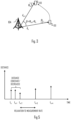
- Figure 3 illustrates an example of the measurements used in the process of Figure 2 .
- the distance of the terminal device 100 from the access node be d n and position be x n (the absolute position x n of the terminal device may be omitted to save power).
- the net effect of motions of the terminal device and the access node can be quantified by looking into the position of the terminal device relative to the position of the access node. In other words, only the distance d n from the access node is of interest.
- TOA time-of-arrival
- the terminal device measures the angles-of-arrival ⁇ n and ⁇ n+1 at measurement instants n and n+1.
- Each measurement instant may be associated with a respective time stamp.
- Antenna arrays (at the access node or the terminal device) and associated spatial signal processing may be used to measure the angle-of-arrival.
- the use of multiple antennas at the access node is less complex.
- Let the measurement time stamps be t n and t n +1 , and corresponding measured angle-of-arrival be ⁇ n and ⁇ n+ 1 , as shown in Figure 3 .
- the distance together with the angular motion may be used for determining the time interval(s) between consecutive RRM measurements, e.g. neighbor cell measurements (and measurement of the serving cell).
- the time interval may be understood to indicate duration to the next radio measurement instant.
- the time interval defines a measurement rate of the RRM measurements.
- the selected measurement rate may be associated with any connectivity state of the terminal device, such as radio resource control (RRC) connected state, RRC, idle state, and RRC inactive state.
- RRC radio resource control
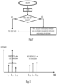
- Figure 4 illustrates a flow diagram of an embodiment of block 202.
- the mobility of the terminal device with respect to the access node is determined in block 400. Let us remind that the terminal device may be mobile and/or the access node may be mobile.
- a first (longer) time interval may be selected in block 402 for the RRM measurements performed by the terminal device.
- the measurement interval may be increased so that the requirements for the RRM measurements are relaxed.
- the longer measurement interval may be maintained, or it may even be lengthened.
- Block 402 may be triggered upon detecting that the distance between the terminal device and the access node is reducing or staying constant.
- v d n + 1 ⁇ d n t n + 1 ⁇ t n .
- block 402 may be entered and the RRM relaxation may be triggered or continued and the longer measurement interval (smaller measurement rate) may be applied to future measurements. This is illustrated in Figure 5 where upon detecting on the basis of multiple measurement occasions that the distance is either decreasing or staying constant, the relaxation to the measurement interval is applied and the measurement rate is reduced.
- ⁇ can be understood as a relative speed threshold having a value representing slow speed such as walking speed (5-7 kilometers per hour) or a fraction of the walking speed.
- angular movement information and the distance metric e.g. RSRP
- the terminal device can utilize the RRM relaxation with a suitable relaxation time derived on the basis of T clk .
- the, measurement interval can be set to a fraction of T clk , e.g. ⁇ T clk where 0 ⁇ 1.
- This embodiment thus uses the angular motion to trigger selection of this function for computing the time T clk and selecting the measurement interval as the fraction of T clk .
- a second time interval shorter than the first time interval is selected.
- the second time interval may be the default time interval, for example. This may be carried out in block 404.
- the second time interval may be computed on the basis of a degree of the angular motion. For example, in a case where v > ⁇ , the terminal device is determined to be moving toward the cell edge.
- the relaxed RRM measurement time interval may then be defined as ⁇ T clk .
- the next measurement occasion t n+ 2 would be at t n +1 + ⁇ T clk . This is illustrated in Figure 6 where, upon detecting that the distance is increasing, a time duration until the terminal device reaches the cell edge (represented by the dotted horizontal line) is computed and a fraction of that time is selected for the measurement interval.
- the terminal device may be assumed to be close to the cell edge so that the default measurement rate (interval) may be applied, as illustrated in Figure 6 with the greater measurement rate after t n+2 , at least for two consecutive measurements in order to determine the motion of the terminal device with respect to the access node at that stage. It may be that the motion vector of the terminal device and/or the access node has changed and that the terminal device is moving towards the access node.
- information indicating a cell edge in terms of a distance to the access node may be stored in a memory, and the distance and the angular motion indicated by the measurement data may be used to estimate a duration until the terminal device reaches the cell edge, and to select the measurement time interval on the basis of the estimated duration.
- the measurement time interval is shorter than the estimated duration to the cell edge to ensure that the further measurements are performed before the terminal device reaches the cell edge.
- block 400 may be used to determine whether the distance is increasing or decreasing. If the distance is determined to be increasing, the distance and the angular motion is used to determine the measurement time interval in block 404. If the distance is determined to be decreasing, the measurement time interval may be determined on the basis of the distance without the angular motion. And if the distance is determined to be constant during the measurement occasion, the angular motion may be used to determine whether or not the motion is rotary, and the measurement time interval may then be computed without the angular motion component, contrary to block 404.
- FIG. 7 illustrates an embodiment of such a process. The process may be carried out in connection with any one of the above-described embodiments. Referring to Figure 7 , after determining the distance and the angular motion, the presence/absence of the line-of-sight may be determined from the distance measurement data, for example.
- the line of sight may be determined to be present, if the distance follows a steady pattern over consecutive measurement occasions (a first set at t n to t n+2 and a second set at t n+3 to t n+5 in Figure 8 ).
- the first set indicates that the distance suddenly increases and then suddenly decreases. Such a pattern indicates the presence of the obstacle that degrades the measurements.
- Other patterns may exist and configuring the process to detect such patterns may be configured to block 700.
- the process may proceed to block 202 or 400, for example.
- the averaging window may be selected and the distance and angular motion measurements may be averaged over the window.
- the average distance value and angle of arrival d m avg and ⁇ m avg can be found.
- the purpose of averaging is to reduce an outlier caused by the measurement data corrupted by the presence of the obstacle.
- the next RRM measurement interval and its relaxation can be selected according to any one of the above-described embodiments.
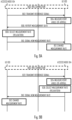
- Figures 9A to 9C illustrate embodiments of determining the measurement rate and communicating the measurement rate between the terminal device and the access node, e.g. by a system comprising the terminal device and the access node.
- steps denoted by the same reference numbers represent the same or substantially similar steps or functions.
- the terminal device (UE) 100 and the access node 104 may establish a RRC connection in block 900.
- step 900 is optional and the embodiments may be carried out in an RRC idle state as well. Establishment and characteristics of the RRC connections are well known to the skilled person from the literature.
- the access node transmits a downlink reference signal and the terminal device receives the reference signal.
- the terminal device measures the reference signal, e.g. the distance metric such as the RSRP or RSSI and the angle-of-arrival.
- the terminal device reports the measurement data to the access node, including, representing, or indicating the distance and the angular motion.
- the access node then carries out the process of Figure 2 or any one of the above-described embodiments and computes the measurement interval (measurement rate) of the terminal device in block 908. Thereafter, the access node transmits to the terminal device a message indicating the new measurement interval (or measurement rate) in step 910.
- the access node may omit step 910 or the message may carry an indication of maintaining the measurement rate.
- the terminal device Upon receiving the new measurement rate, the terminal device changes the measurement rate to follow the new measurement rate in block 912 and carries out the following measurements with the new measurement rate.
- the terminal device performs the measurements on the basis of a downlink reference signal, reports the measurement data to the access node, and the access performs the process of Figure 2 .
- the terminal device transmits an uplink reference signal (step 922) and the access node measures the reference signal received in step 922, generates the respective measurement data (distance and angular motion) in block 924, and performs the process of Figure 2 (block 926). Thereafter, the access node indicates the new measurement interval or measurement rate to the terminal device (step 910) and the terminal device changes the measurement interval (or rate) in block 912, as described above.
- the terminal device may have an option to overrule the new measurement interval. For example, if the terminal device determines that the relaxation cannot be applied although the access node proposes the relaxation, the terminal device may choose the shorter (e.g. default) measurement interval.
- the terminal device receives the downlink reference signal (step 902) and performs the measurements and generation of the measurement data (block 904). Instead of reporting the measurement data to the access node (the report can be optionally made), the terminal device selects the new measurement interval (or measurement rate) in block 930 and reports the selection to the access node in step 932. The access node may then store the current measurement interval. And as described above, the terminal device applies the new measurement interval in block 912. In an embodiment, there are two measurement intervals: the default measurement interval and a relaxed measurement interval, and the indication in step 910 and 932 indicates enablement/disablement of the relaxed measurement interval. Accordingly, the signaling overhead can be reduced.
- the process described above is able to find the relaxed RRM measurement time interval for stationary/low-mobility terminal devices, e.g. the terminal device and the access node are moving but the actual distance between them is not changing or changing only slightly (defined by ⁇ ).
- the procedure may be described as follows. First, the relative speed between the terminal device and the access node is measured by using existing signals such as the reference signals for RSRP or RSSI measurements. The averaging can be optionally applied to reduce the effect of obstacles so that exit from the relaxed measurement interval is not triggered unnecessarily. Then angular (rotatory) motion of the terminal device with respect to the access node is determined by using the distance and the angular motion. Then, an appropriate relaxation to the RRM measurement time interval is determined for the terminal device.
- the terminal device may trigger the RRM relaxation exit condition and start more frequent measurement on the serving cell and optionally the neighbor cells.
- the frequent measurement of the serving cell may be used for the averaging purpose.
- the terminal device may a variation threshold for the distance. For example, if the terminal device determines that the relative speed with respect to the access node is above a certain threshold, more variation in the distance can be allowed without triggering the exit from the relaxed RRM measurements.
- the variation threshold may be used to determine the level of variance in the distance measurements for triggering the averaging, for example, and the variation threshold may be variable as a function of the speed of the terminal device with respect to the access node.
- the measurement interval may be made gradual and a function of various time intervals the terminal device has been determined to be stationary. For example, upon entering the relaxed RRM measurement interval (or rate), the terminal device may start a timer for determining how long the terminal device has been stationary. The measurement interval may be increased in proportion to the determined duration of being stationary. Detection of motion of the terminal device may immediately trigger exit from the relaxed measurement interval and switch to the default or shorter measurement interval.
- a similar solution may be used as a condition for entering the relaxed measurement interval, e.g. the terminal device may need to be stationary with respect to the access node for a determined duration before it is allowed to enter the relaxed measurement interval.
- Figure 10 illustrates an apparatus comprising means for carrying out the process of Figure 2 or any one of the embodiments described above.
- the apparatus may comprise a processing circuitry, such as at least one processor, and at least one memory 40 including computer program code or computer program instructions (software) 44, wherein the at least one memory and the computer program code (software) are configured, with the at least one processor, to cause the apparatus to carry out the process of Figure 2 or any one of its embodiments described above.
- the apparatus may be for the terminal device 100 or for the access node 104.
- the apparatus may be a circuitry or an electronic device realizing some embodiments of the invention in the terminal device 100 or in the access node 104.
- the apparatus carrying out the above-described functionalities may thus be comprised in such a device, e.g.
- the apparatus may comprise a circuitry such as a chip, a chipset, a processor, a micro controller, or a combination of such circuitries for the terminal device 100 or the access node 104.
- the at least one processor or a processing circuitry may realize a communication controller 30 controlling communications in a radio interface of the cellular communication system in the above-described manner.
- the communication controller may comprise an RRC controller 34 configured to establish and manage RRC connections, transfer of data over the RRC connections with the access node 104.
- the communication controller 30 may comprise a measurement controller 35 configured to perform the RRM measurements, e.g. the neighbour cell measurements and the measurements on a radio link with the serving cell.
- the measurement controller 35 may comprise a mobility estimator configured to acquire the above-described measurement data describing the distance and the angular motion between the terminal device and the access node.
- the measurement controller may further comprise a measurement rate controller configured to select the measurement interval on the basis of the measurement data according to any one of the above-described embodiments.
- the apparatus may further comprise an application processor executing one or more computer program applications that generate a need to transmit and/or receive data through the communication controller 10.
- the application processor may form an application layer of the apparatus.
- the application processor may execute computer programs forming the primary function of the apparatus. For example, if the apparatus is a sensor device, the application processor may execute one or more signal processing applications processing measurement data acquired from one or more sensor heads. If the apparatus is a computer system of a vehicle, the application processor may execute a media application and/or an autonomous driving and navigation application. The measurements may be beneficial for the applications to ensure the connectivity of the terminal device with the radio access network.
- the memory 40 may be implemented using any suitable data storage technology, such as semiconductor-based memory devices, flash memory, magnetic memory devices and systems, optical memory devices and systems, fixed memory and removable memory.
- the memory may further store a configuration database storing, for example, the measurement interval and/or criteria for selecting the measurement interval.
- the apparatus may further comprise a communication interface 42 comprising hardware and/or software for providing the apparatus with radio communication capability, as described above.
- the communication interface 42 may include, for example, an antenna, one or more radio frequency filters, a power amplifier, and one or more frequency converters.
- the communication interface 42 may comprise hardware and software needed for realizing the radio communications over the radio interface, e.g. according to specifications of an LTE or 5G radio interface.
- the communication interface may enable the above-described RRM measurements, e.g. the measurement of the reference signals for estimating the distance and the angle-of-arrival.
- circuitry refers to one or more of the following: (a) hardware-only circuit implementations such as implementations in only analog and/or digital circuitry; (b) combinations of circuits and software and/or firmware, such as (as applicable): (i) a combination of processor(s) or processor cores; or (ii) portions of processor(s)/software including digital signal processor(s), software, and at least one memory that work together to cause an apparatus to perform specific functions; and (c) circuits, such as a microprocessor(s) or a portion of a microprocessor(s), that require software or firmware for operation, even if the software or firmware is not physically present.
- the processes or methods described in Figure 3 to 9C may also be carried out in the form of one or more computer processes defined by one or more computer programs.
- the computer program(s) may be in source code form, object code form, or in some intermediate form, and it may be stored in some sort of carrier, which may be any entity or device capable of carrying the program.
- Such carriers include transitory and/or non-transitory computer media, e.g. a record medium, computer memory, read-only memory, electrical carrier signal, telecommunications signal, and software distribution package.
- the computer program may be executed in a single electronic digital processing unit or it may be distributed amongst a number of processing units.
Landscapes
- Engineering & Computer Science (AREA)
- Computer Networks & Wireless Communication (AREA)
- Signal Processing (AREA)
- Databases & Information Systems (AREA)
- Physics & Mathematics (AREA)
- General Physics & Mathematics (AREA)
- Radar, Positioning & Navigation (AREA)
- Remote Sensing (AREA)
- Mobile Radio Communication Systems (AREA)
Claims (16)
- Einrichtung, die Mittel zum Durchführen von Folgendem umfasst:Bestimmen eines Abstands zwischen einem mobilen Zugangsknoten (104) und einer mobilen Endgerätevorrichtung (100) und einer Winkelbewegung der mobilen Endgerätevorrichtung mit Bezug auf den mobilen Zugangsknoten auf Basis von Messdaten, die an einer Funkverbindung gemessen werden, wobei die Winkelbewegung durch Messen eines Ankunftswinkels eines empfangenen Referenzsignals bei verschiedenen Messgelegenheiten mit Bezug auf eine Referenzachse bestimmt wird;Speichern von Informationen, die hinsichtlich eines Abstands zum mobilen Zugangsknoten einen Zellrand anzeigen;Verwenden des Abstands und der Winkelbewegung, die durch die Messdaten angezeigt werden, um eine Dauer zu schätzen, bis die mobile Endgerätevorrichtung den Zellrand erreicht;Treffen einer Entscheidung über eine Länge eines Zeitintervalls zwischen aufeinanderfolgenden Funkmessungen der mobilen Endgerätevorrichtung auf Basis des Abstands, der Winkelbewegung und der geschätzten Dauer; undKommunizieren der Entscheidung über die Funkverbindung oder eine andere Funkverbindung und Veranlassen der mobilen Endgerätevorrichtung, die aufeinanderfolgenden Funkmessungen mit der Länge des Zeitintervalls vorzunehmen; wobei- die Bestimmung, das Speichern, die Schätzung, das Treffen einer Entscheidung und das Kommunizieren alle entweder vom mobilen Zugangsknoten oder von der mobilen Endgerätevorrichtung durchgeführt werden, oder- die Bestimmung von der mobilen Endgerätevorrichtung durchgeführt wird und das Speichern, die Schätzung, das Treffen einer Entscheidung und das Kommunizieren vom mobilen Zugangsknoten durchgeführt werden.
- Einrichtung nach Anspruch 1, wobei das Zeitintervall eine Dauer bis zur nächsten Funkmessinstanz anzeigt.
- Einrichtung nach Anspruch 1 oder 2, wobei die Mittel dazu ausgelegt sind, nach Detektieren, dass der Abstand abnimmt oder beibehalten wird, ein erstes Zeitintervall auszuwählen und nach Detektieren, dass der Abstand zunimmt, ein zweites Zeitintervall auszuwählen, das kürzer ist als das erste Zeitintervall.
- Einrichtung nach Anspruch 3, wobei die Mittel dazu ausgelegt sind, mindestens das zweite Zeitintervall als αTclk zu berechnen, wo Tclk die geschätzte Dauer ist und 0<α<1.
- Einrichtung nach einem der vorhergehenden Ansprüche, wobei das Zeitintervall kürzer ist als die geschätzte Dauer.
- Vorrichtung nach einem der vorhergehenden Ansprüche, wobei die Mittel zu Folgendem ausgelegt sind:Bestimmen, ob der Abstand zunimmt oder abnimmt;wenn bestimmt wird, dass der Abstand zunimmt, Verwenden des Abstands und der Winkelbewegung, um das Zeitintervall zu bestimmen;wenn bestimmt wird, dass der Abstand abnimmt, Bestimmen des Zeitintervalls auf Basis des Abstands ohne die Winkelbewegung.
- Einrichtung nach Anspruch 6, wobei die Mittel dazu ausgelegt sind, wenn bestimmt wird, dass der Abstand zunimmt, Folgendes durchzuführen:wenn bestimmt wird, dass der Abstand zunimmt, aber mit einer Geschwindigkeit, die niedriger ist als ein bestimmter Schwellwert, und wenn bestimmt wird, dass die Winkelbewegung nicht null ist, Berechnen des Zeitintervalls auf Basis eines Abstands zu einem Rand einer Zelle, der vom mobilen Zugangsknoten und vom Schwellwert bereitgestellt wird; undwenn bestimmt wird, dass der Abstand mit einer Geschwindigkeit zunimmt, die größer ist als der Schwellwert, Berechnen des Zeitintervalls auf Basis des Abstands zum Zellrand, der Geschwindigkeit und der Winkelbewegung.
- Einrichtung nach einem der vorhergehenden Ansprüche, wobei die Mittel dazu ausgelegt sind, auf Basis der Messdaten zu bestimmen, ob es zwischen der mobilen Endgerätevorrichtung und dem mobilen Zugangsknoten eine Sichtlinie gibt, und, nach Bestimmen, dass es keine Sichtlinie gibt, Mitteln des Abstands und der Winkelbewegung über ein Messfenster.
- Verfahren, das Folgendes umfasst:Bestimmen (200, 904, 924) eines Abstands zwischen einem mobilen Zugangsknoten (104) und einer mobilen Endgerätevorrichtung (100) und einer Winkelbewegung der mobilen Endgerätevorrichtung mit Bezug auf den mobilen Zugangsknoten auf Basis von Messdaten, die an einer Funkverbindung gemessen werden, wobei die Winkelbewegung durch Messen eines Ankunftswinkels eines empfangenen Referenzsignals (902, 922) bei verschiedenen Messgelegenheiten mit Bezug auf eine Referenzachse bestimmt wird;Speichern von Informationen, die hinsichtlich eines Abstands zum mobilen Zugangsknoten einen Zellrand anzeigen;Verwenden des Abstands und der Winkelbewegung, die durch die Messdaten angezeigt werden, um eine Dauer zu schätzen, bis die mobile Endgerätevorrichtung den Zellrand erreicht;Treffen (202, 908, 926, 930) einer Entscheidung über eine Länge eines Zeitintervalls zwischen aufeinanderfolgenden Funkmessungen der mobilen Endgerätevorrichtung auf Basis des Abstands, der Winkelbewegung und der geschätzten Dauer; undKommunizieren (204, 910, 932) der Entscheidung über die Funkverbindung oder eine andere Funkverbindung und Veranlassen der mobilen Endgerätevorrichtung, die aufeinanderfolgenden Funkmessungen mit der Länge des Zeitintervalls vorzunehmen; wobei- das Verfahren vom mobilen Zugangsknoten oder von der mobilen Endgerätevorrichtung durchgeführt wird, oder- die Bestimmung von der mobilen Endgerätevorrichtung durchgeführt wird und das Speichern, die Schätzung, das Treffen einer Entscheidung und das Kommunizieren vom mobilen Zugangsknoten durchgeführt werden.
- Verfahren nach Anspruch 9, wobei nach Detektieren, dass der Abstand abnimmt oder beibehalten wird, ein erstes Zeitintervall ausgewählt wird und wobei nach Detektieren, dass der Abstand zunimmt, ein zweites Zeitintervall ausgewählt wird, das kürzer ist als das erste Zeitintervall.
- Verfahren nach Anspruch 10, wobei mindestens das zweite Zeitintervall als αTclk berechnet wird, wo Tclk die geschätzte Dauer ist und 0<α<1.
- Verfahren nach einem der vorhergehenden Ansprüche 9 bis 11, das ferner Folgendes umfasst:Bestimmen, ob der Abstand zunimmt oder abnimmt;wenn bestimmt wird, dass der Abstand zunimmt, Verwenden des Abstands und der Winkelbewegung, um das Zeitintervall zu bestimmen;wenn bestimmt wird, dass der Abstand abnimmt, Bestimmen des Zeitintervalls auf Basis des Abstands ohne die Winkelbewegung.
- Verfahren nach einem der vorhergehenden Ansprüche 9 bis 12, das das Bestimmen auf Basis der Messdaten, ob es zwischen der mobilen Endgerätevorrichtung und dem mobilen Zugangsknoten eine Sichtlinie gibt, und, nach Bestimmen, dass es keine Sichtlinie gibt, das Mitteln des Abstands und der Winkelbewegung über ein Messfenster umfasst.
- Verfahren nach einem der vorhergehenden Ansprüche 9 bis 13, wobei das Verfahren von der mobilen Endgerätevorrichtung durchgeführt wird und wobei das Kommunizieren (932) das Übertragen des Zeitintervalls durch die mobile Endgerätevorrichtung zum mobilen Zugangsknoten umfasst.
- Verfahren nach einem der vorhergehenden Ansprüche 9 bis 13, wobei das Verfahren vom mobilen Zugangsknoten durchgeführt wird, und wobei der mobile Zugangsknoten die mobile Endgerätevorrichtung dazu ausgelegt, die Messungen durch Übertragen (910) des Zeitintervalls zur mobilen Endgerätevorrichtung vorzunehmen.
- Computerprogrammprodukt, das sich auf einem computerlesbaren Medium befindet und einen Computerprogrammcode umfasst, der von einem Computer lesbar ist, wobei der Computerprogrammcode den Computer dazu auslegt, einen Computerprozess umzusetzen, der Folgendes umfasst:Bestimmen eines Abstands zwischen einem mobilen Zugangsknoten (104) und einer mobilen Endgerätevorrichtung (100) und einer Winkelbewegung der mobilen Endgerätevorrichtung mit Bezug auf den mobilen Zugangsknoten auf Basis von Messdaten, die an einer Funkverbindung gemessen werden, wobei die Winkelbewegung durch Messen eines Ankunftswinkels eines empfangenen Referenzsignals bei verschiedenen Messgelegenheiten mit Bezug auf eine Referenzachse bestimmt wird;Speichern von Informationen, die hinsichtlich eines Abstands zum mobilen Zugangsknoten einen Zellrand anzeigen;Verwenden des Abstands und der Winkelbewegung, die durch die Messdaten angezeigt werden, um eine Dauer zu schätzen, bis die mobile Endgerätevorrichtung den Zellrand erreicht;Treffen einer Entscheidung über eine Länge eines Zeitintervalls zwischen aufeinanderfolgenden Funkmessungen der mobilen Endgerätevorrichtung auf Basis des Abstands, der Winkelbewegung und der geschätzten Dauer; undKommunizieren der Entscheidung über die Funkverbindung oder eine andere Funkverbindung und Veranlassen der mobilen Endgerätevorrichtung, die aufeinanderfolgenden Funkmessungen mit der Länge des Zeitintervalls vorzunehmen; wobei- die Bestimmung, das Speichern, die Schätzung, das Treffen einer Entscheidung und das Kommunizieren alle entweder vom mobilen Zugangsknoten oder von der mobilen Endgerätevorrichtung durchgeführt werden, oder- die Bestimmung von der mobilen Endgerätevorrichtung durchgeführt wird und das Speichern, die Schätzung, das Treffen einer Entscheidung und das Kommunizieren vom mobilen Zugangsknoten durchgeführt werden.
Applications Claiming Priority (1)
| Application Number | Priority Date | Filing Date | Title |
|---|---|---|---|
| FI20225199 | 2022-03-07 |
Publications (2)
| Publication Number | Publication Date |
|---|---|
| EP4243522A1 EP4243522A1 (de) | 2023-09-13 |
| EP4243522B1 true EP4243522B1 (de) | 2025-06-25 |
Family
ID=85415191
Family Applications (1)
| Application Number | Title | Priority Date | Filing Date |
|---|---|---|---|
| EP23159531.5A Active EP4243522B1 (de) | 2022-03-07 | 2023-03-02 | Relaxation von ue-messungen |
Country Status (3)
| Country | Link |
|---|---|
| US (1) | US11856554B2 (de) |
| EP (1) | EP4243522B1 (de) |
| CN (1) | CN116723534B (de) |
Families Citing this family (1)
| Publication number | Priority date | Publication date | Assignee | Title |
|---|---|---|---|---|
| US20260093029A1 (en) | 2024-10-02 | 2026-04-02 | GM Global Technology Operations LLC | Networked ecosystem with extended multi-hop proximity ranging |
Family Cites Families (6)
| Publication number | Priority date | Publication date | Assignee | Title |
|---|---|---|---|---|
| EP3289803B1 (de) * | 2015-04-30 | 2019-06-12 | Telefonaktiebolaget LM Ericsson (PUBL) | Entspannte messberichte mit steuerungsebene mit dualer konnektivität |
| CN107708060A (zh) | 2016-08-08 | 2018-02-16 | 索尼公司 | 定位装置、方法、移动节点和无线通信设备 |
| CN114514769B (zh) * | 2019-10-02 | 2024-04-12 | 三星电子株式会社 | 用于在无线通信系统中执行无线电资源管理(rrm)测量的方法和装置 |
| WO2021069077A1 (en) * | 2019-10-10 | 2021-04-15 | Telefonaktiebolaget Lm Ericsson (Publ) | Adaptive user equipment operation mode |
| CN113473556B (zh) * | 2020-03-31 | 2023-06-16 | 华为技术有限公司 | 一种放松测量方法和通信装置 |
| US12200525B2 (en) | 2020-05-08 | 2025-01-14 | Qualcomm Incorporated | RRM relaxation for stationary user equipment |
-
2023
- 2023-03-02 EP EP23159531.5A patent/EP4243522B1/de active Active
- 2023-03-06 CN CN202310205671.0A patent/CN116723534B/zh active Active
- 2023-03-06 US US18/117,836 patent/US11856554B2/en active Active
Also Published As
| Publication number | Publication date |
|---|---|
| CN116723534A (zh) | 2023-09-08 |
| US20230284179A1 (en) | 2023-09-07 |
| EP4243522A1 (de) | 2023-09-13 |
| CN116723534B (zh) | 2024-07-12 |
| US11856554B2 (en) | 2023-12-26 |
Similar Documents
| Publication | Publication Date | Title |
|---|---|---|
| US12308926B2 (en) | Apparatus for selecting radio beams | |
| US20250063534A1 (en) | Sidelink positioning in cellular system | |
| WO2023151921A1 (en) | Assisted positioning of terminal device | |
| US20240353518A1 (en) | Switching positioning state | |
| WO2022043608A1 (en) | Interference estimation for improved reliability of connectivity | |
| US11856554B2 (en) | Relaxation of UE measurements | |
| US12407468B2 (en) | Coupled downlink and uplink reference signals for efficient multi-RTT positioning | |
| US12490222B2 (en) | Enhancing positioning efficiency | |
| US12283984B2 (en) | Compensating for missed positioning reference signals | |
| US12550178B2 (en) | Adaptive cellular access | |
| WO2024223045A1 (en) | Interest metric for plurality of beams | |
| EP4345488B1 (de) | Aktivierung einer positionierungsreferenzeinheit | |
| EP4555342B1 (de) | Referenzinformation für referenzsignalzeitdifferenz | |
| EP4345487B1 (de) | Auswahl einer positionierungsreferenzeinheit | |
| US20240283551A1 (en) | Bandwidth based and/or scenario based feature selection for high line-of-sight/non-line-of-sight classification accuracy | |
| US20250344183A1 (en) | Determining subset of candidate positioning anchors | |
| WO2024094393A1 (en) | Detecting misclassification of line-of-sight or non-line-of-sight indicator | |
| EP4559253A1 (de) | Auf bandbreite und/oder szenario basierende merkmalsauswahl | |
| WO2024165252A1 (en) | Anchor terminal device selection for sidelink positioning |
Legal Events
| Date | Code | Title | Description |
|---|---|---|---|
| PUAI | Public reference made under article 153(3) epc to a published international application that has entered the european phase |
Free format text: ORIGINAL CODE: 0009012 |
|
| STAA | Information on the status of an ep patent application or granted ep patent |
Free format text: STATUS: THE APPLICATION HAS BEEN PUBLISHED |
|
| AK | Designated contracting states |
Kind code of ref document: A1 Designated state(s): AL AT BE BG CH CY CZ DE DK EE ES FI FR GB GR HR HU IE IS IT LI LT LU LV MC ME MK MT NL NO PL PT RO RS SE SI SK SM TR |
|
| STAA | Information on the status of an ep patent application or granted ep patent |
Free format text: STATUS: REQUEST FOR EXAMINATION WAS MADE |
|
| 17P | Request for examination filed |
Effective date: 20240313 |
|
| RBV | Designated contracting states (corrected) |
Designated state(s): AL AT BE BG CH CY CZ DE DK EE ES FI FR GB GR HR HU IE IS IT LI LT LU LV MC ME MK MT NL NO PL PT RO RS SE SI SK SM TR |
|
| REG | Reference to a national code |
Ref country code: DE Ref legal event code: R079 Ipc: G01S0005020000 Ref country code: DE Ref legal event code: R079 Ref document number: 602023004179 Country of ref document: DE Free format text: PREVIOUS MAIN CLASS: H04W0064000000 Ipc: G01S0005020000 |
|
| GRAP | Despatch of communication of intention to grant a patent |
Free format text: ORIGINAL CODE: EPIDOSNIGR1 |
|
| STAA | Information on the status of an ep patent application or granted ep patent |
Free format text: STATUS: GRANT OF PATENT IS INTENDED |
|
| RIC1 | Information provided on ipc code assigned before grant |
Ipc: H04W 64/00 20090101ALI20250120BHEP Ipc: G01S 5/12 20060101ALI20250120BHEP Ipc: G01S 5/02 20100101AFI20250120BHEP |
|
| INTG | Intention to grant announced |
Effective date: 20250130 |
|
| GRAS | Grant fee paid |
Free format text: ORIGINAL CODE: EPIDOSNIGR3 |
|
| GRAA | (expected) grant |
Free format text: ORIGINAL CODE: 0009210 |
|
| STAA | Information on the status of an ep patent application or granted ep patent |
Free format text: STATUS: THE PATENT HAS BEEN GRANTED |
|
| AK | Designated contracting states |
Kind code of ref document: B1 Designated state(s): AL AT BE BG CH CY CZ DE DK EE ES FI FR GB GR HR HU IE IS IT LI LT LU LV MC ME MK MT NL NO PL PT RO RS SE SI SK SM TR |
|
| REG | Reference to a national code |
Ref country code: GB Ref legal event code: FG4D |
|
| REG | Reference to a national code |
Ref country code: CH Ref legal event code: EP |
|
| REG | Reference to a national code |
Ref country code: CH Ref legal event code: EP |
|
| REG | Reference to a national code |
Ref country code: IE Ref legal event code: FG4D |
|
| REG | Reference to a national code |
Ref country code: DE Ref legal event code: R096 Ref document number: 602023004179 Country of ref document: DE |
|
| PG25 | Lapsed in a contracting state [announced via postgrant information from national office to epo] |
Ref country code: FI Free format text: LAPSE BECAUSE OF FAILURE TO SUBMIT A TRANSLATION OF THE DESCRIPTION OR TO PAY THE FEE WITHIN THE PRESCRIBED TIME-LIMIT Effective date: 20250625 |
|
| REG | Reference to a national code |
Ref country code: LT Ref legal event code: MG9D |
|
| PG25 | Lapsed in a contracting state [announced via postgrant information from national office to epo] |
Ref country code: NO Free format text: LAPSE BECAUSE OF FAILURE TO SUBMIT A TRANSLATION OF THE DESCRIPTION OR TO PAY THE FEE WITHIN THE PRESCRIBED TIME-LIMIT Effective date: 20250925 Ref country code: GR Free format text: LAPSE BECAUSE OF FAILURE TO SUBMIT A TRANSLATION OF THE DESCRIPTION OR TO PAY THE FEE WITHIN THE PRESCRIBED TIME-LIMIT Effective date: 20250926 |
|
| PG25 | Lapsed in a contracting state [announced via postgrant information from national office to epo] |
Ref country code: BG Free format text: LAPSE BECAUSE OF FAILURE TO SUBMIT A TRANSLATION OF THE DESCRIPTION OR TO PAY THE FEE WITHIN THE PRESCRIBED TIME-LIMIT Effective date: 20250625 |
|
| PG25 | Lapsed in a contracting state [announced via postgrant information from national office to epo] |
Ref country code: HR Free format text: LAPSE BECAUSE OF FAILURE TO SUBMIT A TRANSLATION OF THE DESCRIPTION OR TO PAY THE FEE WITHIN THE PRESCRIBED TIME-LIMIT Effective date: 20250625 |
|
| PG25 | Lapsed in a contracting state [announced via postgrant information from national office to epo] |
Ref country code: RS Free format text: LAPSE BECAUSE OF FAILURE TO SUBMIT A TRANSLATION OF THE DESCRIPTION OR TO PAY THE FEE WITHIN THE PRESCRIBED TIME-LIMIT Effective date: 20250925 |
|
| PG25 | Lapsed in a contracting state [announced via postgrant information from national office to epo] |
Ref country code: LV Free format text: LAPSE BECAUSE OF FAILURE TO SUBMIT A TRANSLATION OF THE DESCRIPTION OR TO PAY THE FEE WITHIN THE PRESCRIBED TIME-LIMIT Effective date: 20250625 |
|
| REG | Reference to a national code |
Ref country code: NL Ref legal event code: MP Effective date: 20250625 |
|
| PG25 | Lapsed in a contracting state [announced via postgrant information from national office to epo] |
Ref country code: NL Free format text: LAPSE BECAUSE OF FAILURE TO SUBMIT A TRANSLATION OF THE DESCRIPTION OR TO PAY THE FEE WITHIN THE PRESCRIBED TIME-LIMIT Effective date: 20250625 |
|
| PG25 | Lapsed in a contracting state [announced via postgrant information from national office to epo] |
Ref country code: PT Free format text: LAPSE BECAUSE OF FAILURE TO SUBMIT A TRANSLATION OF THE DESCRIPTION OR TO PAY THE FEE WITHIN THE PRESCRIBED TIME-LIMIT Effective date: 20251027 |
|
| REG | Reference to a national code |
Ref country code: AT Ref legal event code: MK05 Ref document number: 1806996 Country of ref document: AT Kind code of ref document: T Effective date: 20250625 |
|
| PG25 | Lapsed in a contracting state [announced via postgrant information from national office to epo] |
Ref country code: IS Free format text: LAPSE BECAUSE OF FAILURE TO SUBMIT A TRANSLATION OF THE DESCRIPTION OR TO PAY THE FEE WITHIN THE PRESCRIBED TIME-LIMIT Effective date: 20251025 |
|
| PG25 | Lapsed in a contracting state [announced via postgrant information from national office to epo] |
Ref country code: AT Free format text: LAPSE BECAUSE OF FAILURE TO SUBMIT A TRANSLATION OF THE DESCRIPTION OR TO PAY THE FEE WITHIN THE PRESCRIBED TIME-LIMIT Effective date: 20250625 Ref country code: SM Free format text: LAPSE BECAUSE OF FAILURE TO SUBMIT A TRANSLATION OF THE DESCRIPTION OR TO PAY THE FEE WITHIN THE PRESCRIBED TIME-LIMIT Effective date: 20250625 |
|
| PG25 | Lapsed in a contracting state [announced via postgrant information from national office to epo] |
Ref country code: CZ Free format text: LAPSE BECAUSE OF FAILURE TO SUBMIT A TRANSLATION OF THE DESCRIPTION OR TO PAY THE FEE WITHIN THE PRESCRIBED TIME-LIMIT Effective date: 20250625 |
|
| PG25 | Lapsed in a contracting state [announced via postgrant information from national office to epo] |
Ref country code: PL Free format text: LAPSE BECAUSE OF FAILURE TO SUBMIT A TRANSLATION OF THE DESCRIPTION OR TO PAY THE FEE WITHIN THE PRESCRIBED TIME-LIMIT Effective date: 20250625 |
|
| PG25 | Lapsed in a contracting state [announced via postgrant information from national office to epo] |
Ref country code: EE Free format text: LAPSE BECAUSE OF FAILURE TO SUBMIT A TRANSLATION OF THE DESCRIPTION OR TO PAY THE FEE WITHIN THE PRESCRIBED TIME-LIMIT Effective date: 20250625 |
|
| PG25 | Lapsed in a contracting state [announced via postgrant information from national office to epo] |
Ref country code: SK Free format text: LAPSE BECAUSE OF FAILURE TO SUBMIT A TRANSLATION OF THE DESCRIPTION OR TO PAY THE FEE WITHIN THE PRESCRIBED TIME-LIMIT Effective date: 20250625 |
|
| PG25 | Lapsed in a contracting state [announced via postgrant information from national office to epo] |
Ref country code: ES Free format text: LAPSE BECAUSE OF FAILURE TO SUBMIT A TRANSLATION OF THE DESCRIPTION OR TO PAY THE FEE WITHIN THE PRESCRIBED TIME-LIMIT Effective date: 20250625 |
|
| REG | Reference to a national code |
Ref country code: DE Ref legal event code: R097 Ref document number: 602023004179 Country of ref document: DE |
|
| PG25 | Lapsed in a contracting state [announced via postgrant information from national office to epo] |
Ref country code: DK Free format text: LAPSE BECAUSE OF FAILURE TO SUBMIT A TRANSLATION OF THE DESCRIPTION OR TO PAY THE FEE WITHIN THE PRESCRIBED TIME-LIMIT Effective date: 20250625 |
|
| PGFP | Annual fee paid to national office [announced via postgrant information from national office to epo] |
Ref country code: DE Payment date: 20260204 Year of fee payment: 4 |
|
| PG25 | Lapsed in a contracting state [announced via postgrant information from national office to epo] |
Ref country code: IT Free format text: LAPSE BECAUSE OF FAILURE TO SUBMIT A TRANSLATION OF THE DESCRIPTION OR TO PAY THE FEE WITHIN THE PRESCRIBED TIME-LIMIT Effective date: 20250625 |
|
| PLBE | No opposition filed within time limit |
Free format text: ORIGINAL CODE: 0009261 |
|
| STAA | Information on the status of an ep patent application or granted ep patent |
Free format text: STATUS: NO OPPOSITION FILED WITHIN TIME LIMIT |
|
| REG | Reference to a national code |
Ref country code: CH Ref legal event code: L10 Free format text: ST27 STATUS EVENT CODE: U-0-0-L10-L00 (AS PROVIDED BY THE NATIONAL OFFICE) Effective date: 20260507 |