EP4243178A1 - Endkappe, batteriezelle, batterie und stromverbrauchende vorrichtung - Google Patents
Endkappe, batteriezelle, batterie und stromverbrauchende vorrichtung Download PDFInfo
- Publication number
- EP4243178A1 EP4243178A1 EP22877747.0A EP22877747A EP4243178A1 EP 4243178 A1 EP4243178 A1 EP 4243178A1 EP 22877747 A EP22877747 A EP 22877747A EP 4243178 A1 EP4243178 A1 EP 4243178A1
- Authority
- EP
- European Patent Office
- Prior art keywords
- recess
- end cap
- electrode assembly
- pressure relief
- battery cell
- Prior art date
- Legal status (The legal status is an assumption and is not a legal conclusion. Google has not performed a legal analysis and makes no representation as to the accuracy of the status listed.)
- Pending
Links
- 239000000243 solution Substances 0.000 description 20
- 230000007246 mechanism Effects 0.000 description 11
- 239000008151 electrolyte solution Substances 0.000 description 6
- 239000007773 negative electrode material Substances 0.000 description 6
- 239000007774 positive electrode material Substances 0.000 description 6
- 230000032683 aging Effects 0.000 description 5
- 229910001416 lithium ion Inorganic materials 0.000 description 5
- HBBGRARXTFLTSG-UHFFFAOYSA-N Lithium ion Chemical compound [Li+] HBBGRARXTFLTSG-UHFFFAOYSA-N 0.000 description 4
- 230000009471 action Effects 0.000 description 4
- 238000010586 diagram Methods 0.000 description 4
- 238000013461 design Methods 0.000 description 3
- 238000005516 engineering process Methods 0.000 description 3
- 238000004880 explosion Methods 0.000 description 3
- 239000007789 gas Substances 0.000 description 3
- 239000007788 liquid Substances 0.000 description 3
- 239000004698 Polyethylene Substances 0.000 description 2
- 239000004743 Polypropylene Substances 0.000 description 2
- 230000000712 assembly Effects 0.000 description 2
- 238000000429 assembly Methods 0.000 description 2
- 230000007797 corrosion Effects 0.000 description 2
- 238000005260 corrosion Methods 0.000 description 2
- 238000011161 development Methods 0.000 description 2
- 230000018109 developmental process Effects 0.000 description 2
- 238000007599 discharging Methods 0.000 description 2
- 230000000694 effects Effects 0.000 description 2
- 230000006872 improvement Effects 0.000 description 2
- 239000000463 material Substances 0.000 description 2
- VNWKTOKETHGBQD-UHFFFAOYSA-N methane Chemical compound C VNWKTOKETHGBQD-UHFFFAOYSA-N 0.000 description 2
- 229920000573 polyethylene Polymers 0.000 description 2
- -1 polypropylene Polymers 0.000 description 2
- 229920001155 polypropylene Polymers 0.000 description 2
- 230000002028 premature Effects 0.000 description 2
- OKTJSMMVPCPJKN-UHFFFAOYSA-N Carbon Chemical compound [C] OKTJSMMVPCPJKN-UHFFFAOYSA-N 0.000 description 1
- RYGMFSIKBFXOCR-UHFFFAOYSA-N Copper Chemical compound [Cu] RYGMFSIKBFXOCR-UHFFFAOYSA-N 0.000 description 1
- WHXSMMKQMYFTQS-UHFFFAOYSA-N Lithium Chemical compound [Li] WHXSMMKQMYFTQS-UHFFFAOYSA-N 0.000 description 1
- JLVVSXFLKOJNIY-UHFFFAOYSA-N Magnesium ion Chemical compound [Mg+2] JLVVSXFLKOJNIY-UHFFFAOYSA-N 0.000 description 1
- FKNQFGJONOIPTF-UHFFFAOYSA-N Sodium cation Chemical compound [Na+] FKNQFGJONOIPTF-UHFFFAOYSA-N 0.000 description 1
- IDSMHEZTLOUMLM-UHFFFAOYSA-N [Li].[O].[Co] Chemical class [Li].[O].[Co] IDSMHEZTLOUMLM-UHFFFAOYSA-N 0.000 description 1
- JDZCKJOXGCMJGS-UHFFFAOYSA-N [Li].[S] Chemical compound [Li].[S] JDZCKJOXGCMJGS-UHFFFAOYSA-N 0.000 description 1
- 229910052782 aluminium Inorganic materials 0.000 description 1
- XAGFODPZIPBFFR-UHFFFAOYSA-N aluminium Chemical compound [Al] XAGFODPZIPBFFR-UHFFFAOYSA-N 0.000 description 1
- OJIJEKBXJYRIBZ-UHFFFAOYSA-N cadmium nickel Chemical compound [Ni].[Cd] OJIJEKBXJYRIBZ-UHFFFAOYSA-N 0.000 description 1
- 229910052799 carbon Inorganic materials 0.000 description 1
- 230000008859 change Effects 0.000 description 1
- 238000006243 chemical reaction Methods 0.000 description 1
- 238000004891 communication Methods 0.000 description 1
- 238000010276 construction Methods 0.000 description 1
- 229910052802 copper Inorganic materials 0.000 description 1
- 239000010949 copper Substances 0.000 description 1
- 238000005336 cracking Methods 0.000 description 1
- 230000001351 cycling effect Effects 0.000 description 1
- QHGJSLXSVXVKHZ-UHFFFAOYSA-N dilithium;dioxido(dioxo)manganese Chemical compound [Li+].[Li+].[O-][Mn]([O-])(=O)=O QHGJSLXSVXVKHZ-UHFFFAOYSA-N 0.000 description 1
- 230000005611 electricity Effects 0.000 description 1
- 239000012634 fragment Substances 0.000 description 1
- 239000000446 fuel Substances 0.000 description 1
- 239000002737 fuel gas Substances 0.000 description 1
- 229910052739 hydrogen Inorganic materials 0.000 description 1
- 239000001257 hydrogen Substances 0.000 description 1
- 229910052744 lithium Inorganic materials 0.000 description 1
- 229910000625 lithium cobalt oxide Inorganic materials 0.000 description 1
- GELKBWJHTRAYNV-UHFFFAOYSA-K lithium iron phosphate Chemical compound [Li+].[Fe+2].[O-]P([O-])([O-])=O GELKBWJHTRAYNV-UHFFFAOYSA-K 0.000 description 1
- 238000003754 machining Methods 0.000 description 1
- 229910001425 magnesium ion Inorganic materials 0.000 description 1
- WJZHMLNIAZSFDO-UHFFFAOYSA-N manganese zinc Chemical compound [Mn].[Zn] WJZHMLNIAZSFDO-UHFFFAOYSA-N 0.000 description 1
- 229910052751 metal Inorganic materials 0.000 description 1
- 239000002184 metal Substances 0.000 description 1
- 229910021645 metal ion Inorganic materials 0.000 description 1
- 238000012986 modification Methods 0.000 description 1
- 230000004048 modification Effects 0.000 description 1
- 239000003345 natural gas Substances 0.000 description 1
- 238000012545 processing Methods 0.000 description 1
- 239000000565 sealant Substances 0.000 description 1
- 238000007789 sealing Methods 0.000 description 1
- 229910052710 silicon Inorganic materials 0.000 description 1
- 239000010703 silicon Substances 0.000 description 1
- 229910001415 sodium ion Inorganic materials 0.000 description 1
- 239000000126 substance Substances 0.000 description 1
- 238000006467 substitution reaction Methods 0.000 description 1
Images


Classifications
-
- H—ELECTRICITY
- H01—ELECTRIC ELEMENTS
- H01M—PROCESSES OR MEANS, e.g. BATTERIES, FOR THE DIRECT CONVERSION OF CHEMICAL ENERGY INTO ELECTRICAL ENERGY
- H01M50/00—Constructional details or processes of manufacture of the non-active parts of electrochemical cells other than fuel cells, e.g. hybrid cells
- H01M50/20—Mountings; Secondary casings or frames; Racks, modules or packs; Suspension devices; Shock absorbers; Transport or carrying devices; Holders
- H01M50/204—Racks, modules or packs for multiple batteries or multiple cells
- H01M50/207—Racks, modules or packs for multiple batteries or multiple cells characterised by their shape
- H01M50/209—Racks, modules or packs for multiple batteries or multiple cells characterised by their shape adapted for prismatic or rectangular cells
-
- H—ELECTRICITY
- H01—ELECTRIC ELEMENTS
- H01M—PROCESSES OR MEANS, e.g. BATTERIES, FOR THE DIRECT CONVERSION OF CHEMICAL ENERGY INTO ELECTRICAL ENERGY
- H01M50/00—Constructional details or processes of manufacture of the non-active parts of electrochemical cells other than fuel cells, e.g. hybrid cells
- H01M50/30—Arrangements for facilitating escape of gases
- H01M50/342—Non-re-sealable arrangements
-
- H—ELECTRICITY
- H01—ELECTRIC ELEMENTS
- H01M—PROCESSES OR MEANS, e.g. BATTERIES, FOR THE DIRECT CONVERSION OF CHEMICAL ENERGY INTO ELECTRICAL ENERGY
- H01M10/00—Secondary cells; Manufacture thereof
- H01M10/05—Accumulators with non-aqueous electrolyte
- H01M10/058—Construction or manufacture
- H01M10/0585—Construction or manufacture of accumulators having only flat construction elements, i.e. flat positive electrodes, flat negative electrodes and flat separators
-
- H—ELECTRICITY
- H01—ELECTRIC ELEMENTS
- H01M—PROCESSES OR MEANS, e.g. BATTERIES, FOR THE DIRECT CONVERSION OF CHEMICAL ENERGY INTO ELECTRICAL ENERGY
- H01M50/00—Constructional details or processes of manufacture of the non-active parts of electrochemical cells other than fuel cells, e.g. hybrid cells
- H01M50/10—Primary casings; Jackets or wrappings
- H01M50/102—Primary casings; Jackets or wrappings characterised by their shape or physical structure
- H01M50/103—Primary casings; Jackets or wrappings characterised by their shape or physical structure prismatic or rectangular
-
- H—ELECTRICITY
- H01—ELECTRIC ELEMENTS
- H01M—PROCESSES OR MEANS, e.g. BATTERIES, FOR THE DIRECT CONVERSION OF CHEMICAL ENERGY INTO ELECTRICAL ENERGY
- H01M50/00—Constructional details or processes of manufacture of the non-active parts of electrochemical cells other than fuel cells, e.g. hybrid cells
- H01M50/10—Primary casings; Jackets or wrappings
- H01M50/147—Lids or covers
- H01M50/148—Lids or covers characterised by their shape
- H01M50/15—Lids or covers characterised by their shape for prismatic or rectangular cells
-
- H—ELECTRICITY
- H01—ELECTRIC ELEMENTS
- H01M—PROCESSES OR MEANS, e.g. BATTERIES, FOR THE DIRECT CONVERSION OF CHEMICAL ENERGY INTO ELECTRICAL ENERGY
- H01M50/00—Constructional details or processes of manufacture of the non-active parts of electrochemical cells other than fuel cells, e.g. hybrid cells
- H01M50/20—Mountings; Secondary casings or frames; Racks, modules or packs; Suspension devices; Shock absorbers; Transport or carrying devices; Holders
- H01M50/204—Racks, modules or packs for multiple batteries or multiple cells
-
- H—ELECTRICITY
- H01—ELECTRIC ELEMENTS
- H01M—PROCESSES OR MEANS, e.g. BATTERIES, FOR THE DIRECT CONVERSION OF CHEMICAL ENERGY INTO ELECTRICAL ENERGY
- H01M2220/00—Batteries for particular applications
- H01M2220/20—Batteries in motive systems, e.g. vehicle, ship, plane
-
- H—ELECTRICITY
- H01—ELECTRIC ELEMENTS
- H01M—PROCESSES OR MEANS, e.g. BATTERIES, FOR THE DIRECT CONVERSION OF CHEMICAL ENERGY INTO ELECTRICAL ENERGY
- H01M2220/00—Batteries for particular applications
- H01M2220/30—Batteries in portable systems, e.g. mobile phone, laptop
-
- Y—GENERAL TAGGING OF NEW TECHNOLOGICAL DEVELOPMENTS; GENERAL TAGGING OF CROSS-SECTIONAL TECHNOLOGIES SPANNING OVER SEVERAL SECTIONS OF THE IPC; TECHNICAL SUBJECTS COVERED BY FORMER USPC CROSS-REFERENCE ART COLLECTIONS [XRACs] AND DIGESTS
- Y02—TECHNOLOGIES OR APPLICATIONS FOR MITIGATION OR ADAPTATION AGAINST CLIMATE CHANGE
- Y02E—REDUCTION OF GREENHOUSE GAS [GHG] EMISSIONS, RELATED TO ENERGY GENERATION, TRANSMISSION OR DISTRIBUTION
- Y02E60/00—Enabling technologies; Technologies with a potential or indirect contribution to GHG emissions mitigation
- Y02E60/10—Energy storage using batteries
Definitions
- the present application relates to the field of batteries, and particularly to an end cap, a battery cell, a battery and a power consuming device.
- Battery cells are widely used in electronic devices, such as a mobile phone, a notebook computer, an electromobile, an electric vehicle, an electric airplane, an electric ship, an electric toy car, an electric toy ship, an electric toy airplane, and an electric tool.
- the battery cells may include a nickel-cadmium battery cell, a nickel-hydrogen battery cell, a lithium-ion battery cell, a secondary alkaline zinc-manganese battery cell, etc.
- the present application provides an end cap, a battery cell, a battery and a power consuming device, which can improve the safety of the battery cell.
- an embodiment of the present application provides an end cap of a battery cell, the end cap including:
- the pressure relief portion when the battery cell is short-circuited or overcharged, the pressure relief portion is partially broken and folded outward to form a channel for relief of the internal pressure, so as to reduce the risk of explosion or fire of the battery cell, thereby improving the safety.
- the side of the second part facing away from the electrode assembly forms the avoidance space to reduce the risk of the pressure relief portion being blocked by other parts of the end cap, thereby ensuring the internal-pressure relief efficiency and improving the safety of the battery cell.
- the bottom wall of the first recess and/or the first part is provided with a third recess, and the pressure relief portion is configured to be broken at the third recess to relieve the internal pressure when the internal pressure of the battery cell reaches the threshold.
- the pressure relief portion may be broken and folded along a predetermined position when the internal pressure of the battery cell reaches the threshold.
- a projection of the third recess in the thickness direction is linear, cross-shaped, U-shaped or ring-shaped.
- the third recess is ring-shaped and includes a first sub-recess and a second sub-recess that are continuously provided along its own circumference, and the first sub-recess has a depth greater than that of the second sub-recess so that when the internal pressure of the battery cell reaches the threshold, the pressure relief portion is broken at the first sub-recess and folded along the bottom of the second sub-recess.
- the pressure relief portion is broken at a predetermined position and a folding direction of the pressure relief portion is limited.
- the second sub-recess is provided at the folding position, so that the difficulty in folding the pressure relief portion can be reduced and the internal-pressure relief efficiency can be improved.
- the end cap includes: a body portion including an inner surface and an outer surface arranged opposite to each other in the thickness direction, the inner surface facing toward the electrode assembly; a first protrusion protruding from the inner surface, wherein the first recess is recessed from a top end face of the first protrusion in the direction away from the electrode assembly; and a second protrusion protruding from the outer surface, wherein the second recess is recessed from a top end face of the second protrusion in the direction toward the electrode assembly.
- the first protrusion and the second protrusion are provided to increase the strength of the end cap around the pressure relief portion, reduce deformation of the pressure relief portion during back and forth flipping of the end cap, reduce an acting force transmitted to the pressure relief portion, slow down fatigue aging of the pressure relief portion, and reduce the risk of premature breakage of the end cap under the normal use of the battery cell, facilitating improvement of the safety and stability of the battery cell.
- the second recess has a depth in the thickness direction that is greater than a size of the second protrusion in the thickness direction, so that the bottom wall of the second recess is closer to the electrode assembly than the outer surface.
- the above solution ensures that the depth of the second recess increases an interval between the bottom wall of the second recess and the top end face of the second protrusion in the thickness direction, thereby reducing the risk of the pressure relief portion being damaged by an external member and improving the safety.
- the first recess has a depth in the thickness direction that is less than a size of the first protrusion in the thickness direction, so that the bottom wall of the first recess is closer to the electrode assembly than the inner surface.
- the first protrusion in the thickness direction, has a size greater than that of the second protrusion.
- the second protrusion has a relatively small size, so that the maximum size of the battery cell can be reduced, increasing the energy density.
- the end cap further includes: a connecting portion surrounding an outer side of the body portion and extending in the direction toward the electrode assembly to form a fourth recess on the side of the body portion facing toward the electrode assembly; and a plate portion surrounding an outer side of the connecting portion, the fourth recess being recessed relative to the surface of the plate portion facing toward the electrode assembly, wherein the first protrusion is accommodated in the fourth recess.
- an inner space of the battery cell may be increased, thereby increasing the capacity of the battery cell.
- the fourth recess can also provide a space for the first protrusion so that the first protrusion protrudes enough so that the first protrusion is prevent from abutting against the electrode assembly.
- the end cap is of an integrally formed structure.
- the pressure relief portion having a pressure relief function is integrated onto the end cap, so that the structure of the battery cell is simplified.
- an embodiment of the present application provides a battery cell, including: a housing provided with an opening; an electrode assembly accommodated in the housing; and the end cap according to any embodiment in the first aspect, configured to cover the opening of the housing.
- an embodiment of the present application provides a battery, including a case and the battery cell in the second aspect, the battery cell being received in the case.
- an embodiment of the present application provides a power consuming device, including the battery in the third aspect, the battery being configured to supply electric energy.
- the terms “mount”, “connected”, “connect”, or “attach” should be interpreted in a broad sense unless explicitly defined and limited otherwise. For example, they may be a fixed connection, a detachable connection, or an integral connection; or may be a direct connection, an indirect connection by means of an intermediate medium, or internal communication between two elements.
- the specific meaning of the foregoing term in the present application may be understood according to specific circumstances.
- a and/or B may be expressed as: the three instances of A alone, A and B simultaneously, and B alone.
- the character "/" in the present application generally indicates that the associated objects before and after the character are in a relationship of "or".
- a plurality of appearing in the present application means two or more (including two).
- a battery cell may include a lithium-ion secondary battery cell, a lithium-ion primary battery cell, a lithium-sulfur battery cell, a sodium-lithium-ion battery cell, a sodium-ion battery cell, a magnesium-ion battery cell, or the like, which is not limited in the embodiments of the present application.
- the battery cell may be cylindrical, flat, cuboid or in another shape, which will also not be limited in the embodiments of the present application.
- a battery mentioned in the embodiments of the present application refers to a single physical module including one or more battery cells to provide a high voltage and capacity.
- the battery mentioned in the present application may include a battery module, a battery pack, etc.
- the battery generally includes a case for enclosing one or more battery cells. The case can prevent liquid or other foreign matters from affecting the charging or discharging of a battery cell.
- the battery cell includes an electrode assembly and an electrolyte solution.
- the electrode assembly includes a positive electrode plate, a negative electrode plate, and a separator.
- the battery cell operates mainly by relying on movements of metal ions between the positive electrode plate and the negative electrode plate.
- the positive electrode plate includes a positive current collector and a positive active material layer. A surface of the positive current collector is coated with the positive active material layer; and the positive current collector includes a positive coated region and a positive tab connected to the positive coated region, the positive coated region is coated with the positive active material layer, and the positive tab is not coated with the positive active material layer.
- the positive current collector may be made of aluminum, and the positive active material layer comprises a positive active material which may be lithium cobalt oxides, lithium iron phosphate, ternary lithium, lithium manganate, etc.
- the negative electrode plate includes a negative current collector and a negative active material layer. A surface of the negative current collector is coated with the negative active material layer; and the negative current collector includes a negative coated region and a negative tab connected to the negative coated region, the negative coated region is coated with the negative active material layer, and the negative tab is not coated with the negative active material layer.
- the negative current collector may be made of copper, and the negative active material layer comprises a negative active material which may be carbon, silicon, etc.
- the separator may be made of polypropylene (PP), polyethylene (PE), etc.
- the battery cell further includes a housing and an end cap.
- the housing is provided with an opening and used to accommodate the electrode assembly.
- the electrode assembly may be assembled into the housing through the opening of the housing.
- the end cap is configured to cover the opening of the housing.
- a pressure relief mechanism on the battery cell has an important effect on the safety of the battery cell. For example, when a phenomenon such as a short circuit or overcharge occurs, the battery cell may be internally subjected to thermal runaway and the pressure may suddenly rise. In this case, the internal pressure can be relieved to outside by actuating the pressure relief mechanism to prevent the battery cell from exploding and catching fire.
- the pressure relief mechanism refers to an element or component that is actuated, when an internal pressure of the battery cell reaches a predetermined threshold, to relieve the internal pressure.
- the threshold design varies according to different design requirements. The threshold may depend on materials of one or more of the positive electrode plate, the negative electrode plate, the electrolyte solution, and the separator in the battery cell.
- the pressure relief mechanism may be in the form of an explosion-proof valve, a gas valve, a pressure relief valve, a safety valve, etc., and may specifically use a pressure-sensitive element or construction. That is, when the internal pressure of the battery cell reaches a predetermined threshold, the pressure relief mechanism performs an action or a weakened structure provided in the pressure relief mechanism is broken, thereby creating an opening or a channel for relief of the internal pressure.
- the "actuated" mentioned in the present application means that the pressure relief mechanism acts or is activated into a certain state, such that the internal pressure of the battery cell is relieved. Actions produced by the pressure relief mechanism may include, but are not limited to, at least a portion of the pressure relief mechanism being broken, cracking, being torn or opened, etc.
- the pressure relief mechanism When the pressure relief mechanism is actuated, high-temperature and high-pressure substances inside the battery cell are discharged outwards from an actuated part as emissions. In this way, the pressure of the battery cell can be relieved at a controllable pressure, thereby preventing the occurrence of potentially more serious accidents.
- the emissions from the battery cell mentioned in the present application include, but are not limited to, the electrolyte solution, dissolved or split positive and negative electrode plates, fragments of the separator, a high-temperature and high-pressure gas generated by a reaction, flames, etc.
- the inventors tried to integrate the pressure relief mechanism onto the end cap.
- the inventors created a recess on the end cap to form a pressure relief portion configured to be actuated, when an internal pressure of the battery cell reaches a threshold, to relieve the internal pressure.
- a phenomenon such as a short circuit or overcharge occurs, the battery cell may be internally subjected to thermal runaway and the pressure may thus suddenly rise.
- the pressure relief portion is partially broken and folded outward to form a channel for relief of the internal pressure, so as to reduce the risk of explosion or fire of the battery cell, thereby improving the safety.
- the inventors discovered the problem of low rate of internal-pressure relief during thermal runaway and then analyzed and studied the structure of the battery cell.
- the inventors found that the position of the pressure relief portion corresponds to the position of the recess, and when the pressure relief portion is folded outward under the action of the internal pressure, the pressure relief portion is likely to be blocked by a side wall of the recess, so that the outward-folding degree of the pressure relief portion is limited, resulting in a low pressure relief rate.
- an end cap of a battery cell includes: a first recess recessed from the side of the end cap facing toward an electrode assembly in a direction away from the electrode assembly; a second recess recessed from the side of the end cap facing away from the electrode assembly of the battery cell in a direction toward the electrode assembly, wherein a bottom wall of the second recess includes a first part and a second part surrounding an outer side of the first part, and the first part and a bottom wall of the first recess are arranged opposite to each other in a thickness direction of the end cap; and a pressure relief portion formed between the first part and the bottom wall of the first recess, wherein the pressure relief portion is configured to be actuated, when an internal pressure of the battery cell reaches a threshold, to relieve the internal pressure, and the side of the second part facing away from the electrode assembly forms an avoidance space to avoid the pressure relief portion when the pressure relief portion is actuated.
- the end cap having such a structure can be actuated, when an internal pressure of the battery cell reaches
- the power consuming device may be a vehicle, a mobile phone, a portable device, a notebook computer, a ship, a spacecraft, an electric toy, an electric tool, etc.
- the vehicle may be a fuel vehicle, a gas vehicle or a new-energy vehicle.
- the new-energy vehicle may be a battery electric vehicle, a hybrid vehicle, an extended-range vehicle, etc.
- the spacecraft includes an airplane, a rocket, an aerospace plane, a spaceship, etc.
- the electric toy includes a stationary or mobile electric toy, such as a game machine, an electric toy car, an electric toy ship, and an electric toy airplane.
- the electric tool includes a metal cutting electric tool, a grinding electric tool, an assembling electric tool, and a railway electric tool, such as an electric drill, an electric grinder, an electric wrench, an electric screwdriver, an electric hammer, an electric impact drill, a concrete vibrator, and an electric planer.
- the power consuming devices are not specifically limited in the embodiments of the present application.
- a power consuming device refers to a vehicle.
- FIG. 1 is a schematic structural diagram of a vehicle provided in some embodiments of the present application.
- a battery 2 is provided inside the vehicle 1, and the battery 2 may be arranged at the bottom, the head or the tail of the vehicle 1.
- the battery 2 may be configured to supply power to the vehicle 1.
- the battery 2 may be used as an operational power supply for the vehicle 1.
- the vehicle 1 may further include a controller 3 and a motor 4, and the controller 3 is configured to control the battery 2 to supply power to the motor 4, for example, to satisfy a working electricity need during start, navigation, and driving of the vehicle 1.
- the battery 2 can not only serve as a power supply for operating the vehicle 1, but also serve as a power supply for driving the vehicle 1, in place of or partially in place of fuel or natural gas, to provide driving power for the vehicle 1.
- FIG. 2 is a schematic exploded view of a battery provided in some embodiments of the present application.
- the battery 2 includes a case 5 and battery cells (not shown in FIG. 2 ) which are accommodated in the case 5.
- the case 5 is configured to accommodate the battery cells, and the case 5 may have various structures.
- the case 5 may include a first case part 5a and a second case part 5b, the first case part 5a and the second case part 5b cover each other, and the first case part 5a and the second case part 5b jointly define an accommodating space 5c for accommodating the battery cells.
- the second case part 5b may be of a hollow structure with one end opened, the first case part 5a is of a plate-like structure, and the first case part 5a covers the open side of the second case part 5b to form the case 5 having the accommodating space 5c.
- the first case part 5a and the second case part 5b each may also be of a hollow structure with one side opened, and the open side of the first case part 5a covers the open side of the second case part 5b to form the case 5 having the accommodating space 5c.
- the first case part 5a and the second case part 5b may have various shapes such as a cylinder and a cuboid.
- a seal such as a sealant and a seal ring, may be also provided between the first case part 5a and the second case part 5b.
- the first case part 5a covers the top of the second case part 5b
- the first case part 5a may also be referred to as an upper case cover
- the second case part 5b may also be referred to as a lower case body.
- one or more battery cells may be provided. If a plurality of battery cells are provided, the plurality of battery cells may be in series connection or parallel connection or series-parallel connection.
- the series-parallel connection means that some of the plurality of battery cells are in series connection and some are in parallel connection.
- the plurality of battery cells may be directly in series connection or parallel connection or series-parallel connection, and then a unit composed of the plurality of battery cells is accommodated in the case 5.
- a plurality of battery cells may also be first in series connection or parallel connection or series-parallel connection to form a battery module 6, and a plurality of battery modules 6 are in series connection or parallel connection or series-parallel connection to form a unit and are accommodated in the case 5.
- FIG. 3 is a schematic exploded view of a battery module shown in FIG. 2 .
- a plurality of battery cells 7 are provided.
- the plurality of battery cells 7 are connected in series or in parallel or in series-parallel to form a battery module 6.
- a plurality of battery modules 6 are in turn connected in series or in parallel or in series-parallel to form a unit and are accommodated in the case.
- the plurality of battery cells 7 in the battery module 6 may be electrically connected to each other by means of a busbar component to implement series connection or parallel connection or series-parallel connection between the plurality of battery cells 7 in the battery module 6.
- a battery cell 7 includes: a housing 20 provided with an opening 21; an electrode assembly 10 accommodated in the housing 20; and an end cap 30 configured to cover the opening 21 of the housing 20.
- the electrode assembly 10 includes a first electrode plate, a second electrode plate, and a separator configured to separate the first electrode plate from the second electrode plate.
- the first electrode plate and the second electrode plate have opposite polarities. In other words, one of the first electrode plate and the second electrode plate is a positive electrode plate, and the other of the first electrode plate and the second electrode plate is a negative electrode plate.
- the first electrode plate, the second electrode plate and the separator each is of a strip-shaped structure, and the first electrode plate, the second electrode plate and the separator are wound as one piece to form a wound structure.
- the wound structure may be a cylindrical structure, a flat structure or a structure of another shape.
- the first electrode plate and the second electrode plate each is of a plate-like structure, a plurality of first electrode plates and a plurality of second electrode plates are provided, and the plurality of first electrode plates and the plurality of second electrode plates are alternately stacked.
- one or more electrode assemblies 10 may be provided according to actual use requirements. In some examples, four separate electrode assemblies 10 are provided in the battery cell 7.
- the housing 20 may be of a hollow structure with an opening on one side, or a hollow structure with openings on two sides.
- the end cap 30 covers the opening 21 of the housing 20 and forms a hermetic connection, thereby forming an accommodating cavity for accommodating the electrode assembly 10 and the electrolyte solution.
- the housing 20 may have various shapes such as a cylinder and a cuboid.
- the housing 20 may be shaped depending on the specific shape of the electrode assembly 10. For example, if the electrode assembly 10 is of a cylindrical structure, a cylindrical housing may be used; and if the electrode assembly 10 is of a cuboid structure, a cuboid housing may be used.
- the battery cell 7 further includes two electrode terminals 40.
- the two electrode terminals 40 may be arranged on the end cap 30.
- the two electrode terminals 40 are a positive electrode terminal and a negative electrode terminal respectively.
- Each electrode terminal 40 is correspondingly provided with a connecting member 50, which may be referred to as a current collecting member and is located between the end cap 30 and the electrode assembly 10 to achieve the electrical connection between the electrode assembly 10 and the electrode terminal 40.
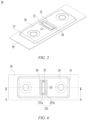
- FIG. 5 is a schematic structural diagram of an end cap of a battery cell provided in some embodiments of the present application
- FIG. 6 is a schematic top view of the end cap shown in FIG. 5
- FIG. 7 is a schematic sectional view of the end cap shown in FIG. 6 taken along line A-A
- FIG. 8 is an enlarged schematic view of the end cap shown in FIG. 7 at circle B.
- the end cap 30 includes: a first recess 31 recessed from the side of the end cap 30 facing toward an electrode assembly in a direction away from the electrode assembly; a second recess 32 recessed from the side of the end cap 30 facing away from the electrode assembly of the battery cell in a direction toward the electrode assembly, wherein a bottom wall 321 of the second recess includes a first part 321a and a second part 321b surrounding an outer side of the first part 321a, and the first part 321a and a bottom wall 311 of the first recess are arranged opposite to each other in a thickness direction Z of the end cap 30; and a pressure relief portion 33 formed between the first part 321a and the bottom wall 311 of the first recess, wherein the pressure relief portion 33 is configured to be actuated, when an internal pressure of the battery cell reaches a threshold, to relieve the internal pressure, and the side of the second part 321b facing away from the electrode assembly forms
- the first recess 31 is located on the side of the pressure relief portion 33 facing toward the electrode assembly, and the second recess 32 is located on the side of the pressure relief portion 33 facing away from the electrode assembly.
- a projection of the first part 321a in the thickness direction Z fully overlaps with a projection of the bottom wall 311 of the first recess in the thickness direction Z, and a projection of the second part 321b in the thickness direction Z does not overlap with the projection of the bottom wall 311 of the first recess in the thickness direction Z.
- the second part 321b is a ring-shaped surface that surrounds the outer side of the first part 321a. Correspondingly, the second part 321b surrounds the outer side of the pressure relief portion 33.
- the bottom wall 311 of the first recess and the bottom wall 321 of the second recess are both planes parallel to each other.
- the second recess 32 further includes a side wall 322.
- the side wall 322 is connected to the bottom wall 321 of the second recess.
- the pressure relief portion 33 When the pressure relief portion 33 is actuated, at least part of the pressure relief portion 33 is broken, and the pressure relief portion 33 is folded outward along the broken position under the action of the internal pressure to form a channel for relieving the internal pressure.
- the inventors created the recess to reduce the thickness of the pressure relief portion so as to further reduce the strength of the pressure relief portion, so that the pressure relief portion can be actuated, when the internal pressure of the battery cell reaches a threshold, to relieve the internal pressure.
- the thickness of the pressure relief portion is specified, if only one side of the pressure relief portion is provided with the recess, the depth of the recess is relatively large, leading to a high difficulty in forming the recess.
- the first recess 31 and the second recess 32 are provided to form the pressure relief portion 33, so that depth requirements of the first recess 31 and the second recess 32 can be reduced, thereby reducing the forming difficulty.
- the depth of the second recess 32 is reduced, so that the risk of the pressure relief portion 33 being blocked by the side wall 322 of the second recess 32 can be reduced when the pressure relief portion 33 is folded outward.
- the second recess 32 is located on the side of the pressure relief portion 33 facing away from the electrode assembly. That is, the second recess 32 is located on the outer side of the pressure relief portion 33.
- an interval between the pressure relief portion 33 and another member outside the battery cell can be increased, reducing the risk of damaging the pressure relief portion 33 by the other member.
- the pressure relief portion 33 when the battery cell is short-circuited or overcharged, the pressure relief portion 33 is partially broken and folded outward to form a channel for relief of the internal pressure to reduce the risk of explosion or fire of the battery cell, thereby improving the safety.
- the side of the second part 321b facing away from the electrode assembly forms the avoidance space to reduce the risk of the pressure relief portion 33 being blocked by other parts of the end cap 30, thereby ensuring the internal-pressure relief efficiency and improving the safety of the battery cell.
- the bottom wall 311 of the first recess and/or the first part 321a is provided with a third recess 331, and the pressure relief portion 33 is configured to be broken at the third recess 331 to relieve the internal pressure when the internal pressure of the battery cell reaches the threshold.
- the third recess 331 may be provided only in the bottom wall 311 of the first recess, or only in the first part 321a, or in both the bottom wall 311 of the first recess and the first part 321a.
- the third recess 331 When the third recess 331 is provided in the bottom wall 311 of the first recess, the third recess 331 is recessed from the bottom wall 311 of the first recess in the direction away from the electrode assembly; and when the third recess 331 is provided in the first part 321a, the third recess 331 is recessed from the first part 321a in the direction toward the electrode assembly.
- a weakened structure of the pressure relief portion 33 is formed by providing the third recess 331.
- the strength of the weakened structure is less than those of other parts of the pressure relief portion 33.
- the third recess 331 may be formed by removing material from the pressure relief portion 33 by means of machining, which facilitates lowering of the processing cost and difficulty.
- the weakened structure and the third recess 331 are arranged corresponding to each other in the thickness direction Z of the end cap 30.
- the third recess 331 may also be formed by extruding the pressure relief portion 33.
- the pressure relief portion 33 may be broken and folded along a predetermined position when the internal pressure of the battery cell reaches the threshold.
- the pressure relief portion 33 when the pressure relief portion 33 is actuated, at least part of the pressure relief portion 33 is folded into the second recess 32. When the pressure relief portion 33 is actuated, the pressure relief portion 33 is folded outward under pushing of the internal pressure.
- the pressure relief portion 33 when the pressure relief portion 33 is actuated, at least part of the pressure relief portion 33 is folded into the avoidance space. In other words, when the pressure relief portion 33 is actuated, the pressure relief portion 33 and the second part 321b overlap at least partially in the thickness direction Z.
- the avoidance space may be used to accommodate at least part of the pressure relief portion 33, so that the folding degree of the pressure relief portion 33 can be increased, so as to reduce the resistance of the pressure relief portion 33 to the internal pressure, thereby improving the internal-pressure relief efficiency.
- the third recess 331 is ring-shaped and includes a first sub-recess 331a and a second sub-recess 331b that are continuously provided along its own circumference, and the first sub-recess 331a has a depth greater than that of the second sub-recess 331b so that when the internal pressure of the battery cell reaches the threshold, the pressure relief portion 33 is broken at the first sub-recess 331a and folded along the bottom of the second sub-recess 331b.
- the strength of the first sub-recess 331a is less than that of the second sub-recess 331b.
- the pressure relief portion 33 is broken at a predetermined position and a folding direction of the pressure relief portion 33 is limited.
- the second sub-recess 331b is provided at the folding position, so that the difficulty in folding the pressure relief portion 33 can be reduced and the internal-pressure relief efficiency can be improved.
- a projection of the second sub-recess 331b in the thickness direction Z is linear.
- the part of the pressure relief portion 33 opposite to the second sub-recess 331b is linear.
- a projection of the third recess 331 in the thickness direction Z is linear, cross-shaped, U-shaped or ring-shaped.
- the end cap 30 includes: a body portion 34 including an inner surface 341 and an outer surface 342 arranged opposite to each other in the thickness direction Z, the inner surface 341 facing toward the electrode assembly; a first protrusion 35 protruding from the inner surface 341, wherein the first recess 31 is recessed from a top end face 351 of the first protrusion in the direction away from the electrode assembly; and a second protrusion 36 protruding from the outer surface 342, wherein the second recess 32 is recessed from a top end face 361 of the second protrusion in the direction toward the electrode assembly.
- the internal pressure of the battery cell varies alternately between high and low levels, resulting in back and forth flipping of the end cap.
- the pressure relief portion may be subjected to fatigue aging, leading to the risk that the pressure relief portion may be actuated before the internal pressure of the battery cell reaches the threshold.
- the first protrusion 35 and the second protrusion 36 are provided to increase the strength of the end cap 30 around the pressure relief portion 33, reduce deformation of the pressure relief portion 33 during back and forth flipping of the end cap 30, reduce an acting force transmitted to the pressure relief portion 33, slow down fatigue aging of the pressure relief portion 33, and reduce the risk of premature breakage of the end cap 30 under the normal use of the battery cell, facilitating improvement of the safety and stability of the battery cell.
- the second recess 32 has a depth in the thickness direction Z that is greater than a size of the second protrusion 36 in the thickness direction Z, so that the bottom wall of the second recess 321 is closer to the electrode assembly than the outer surface 342.
- the depth of the second recess 32 can be ensured to increase an interval between the bottom wall 321 of the second recess and the top end face 361 of the second protrusion in the thickness direction Z, thereby reducing the risk of the pressure relief portion 33 being damaged by an external member and improving the safety.
- the first recess 31 has a depth in the thickness direction Z that is less than a size of the first protrusion 35 in the thickness direction Z, so that the bottom wall 311 of the first recess is closer to the electrode assembly than the inner surface 341.
- the end cap 30 is located on the lower side of the electrode assembly.
- the electrolyte solution is more likely to accumulate on the inner surface 341 than on the bottom wall 311 of the first recess. That is, this embodiment can reduce the amount of liquid stored in the first recess 31 and reduce the risk of aging of the pressure relief portion 33 caused by corrosion.
- the first protrusion 35 has a size greater than that of the second protrusion 36.
- the second protrusion 36 has a relatively small size, so that the maximum size of the battery cell can be reduced, thereby increasing the energy density.
- the end cap 30 further includes: a connecting portion 37 surrounding an outer side of the body portion 34 and extending in the direction toward the electrode assembly to form a fourth recess 38 on the side of the body portion 34 facing toward the electrode assembly; and a plate portion 39 surrounding an outer side of the connecting portion 37, the fourth recess 38 being recessed relative to the surface of the plate portion 39 facing toward the electrode assembly, wherein the first protrusion 35 is accommodated in the fourth recess 38.
- the plate portion 39 is configured to be connected to the housing.
- an inner space of the battery cell may be increased, thereby increasing the capacity of the battery cell.
- the fourth recess 38 can also provide a space for the first protrusion 35 so that the first protrusion 35 protrudes enough so that the first protrusion 35 is prevent from abutting against the electrode assembly.
- the end cap 30 is of an integrally formed structure.
- the pressure relief portion 33 having a pressure relief function is integrated onto the end cap 30, so that the structure of the battery cell is simplified.
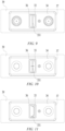
- FIG. 9 is a schematic top view of an end cap provided in some other embodiments of the present application.
- a projection of the third recess 331 in the thickness direction is linear.
- the linear third recess 331 is easy to form.
- FIG. 10 is a schematic top view of an end cap provided in still some other embodiments of the present application.
- the projection of the third recess 331 in the thickness direction is cross-shaped.
- the pressure relief portion 33 is broken at a cross point and divided into four pieces which are folded outward in four directions.
- FIG. 11 is a schematic top view of an end cap provided in yet some other embodiments of the present application.
- the projection of the third recess 331 in the thickness direction is U-shaped.
- the pressure relief portion 33 is broken along the U-shaped third recess 331, and a region enclosed by the U-shaped third recess 331 is folded outward.
Landscapes
- Chemical & Material Sciences (AREA)
- Chemical Kinetics & Catalysis (AREA)
- Electrochemistry (AREA)
- General Chemical & Material Sciences (AREA)
- Engineering & Computer Science (AREA)
- Manufacturing & Machinery (AREA)
- Sealing Battery Cases Or Jackets (AREA)
Applications Claiming Priority (2)
| Application Number | Priority Date | Filing Date | Title |
|---|---|---|---|
| CN202122434797.4U CN216288669U (zh) | 2021-10-09 | 2021-10-09 | 端盖、电池单体、电池以及用电装置 |
| PCT/CN2022/070206 WO2023056719A1 (zh) | 2021-10-09 | 2022-01-05 | 端盖、电池单体、电池以及用电装置 |
Publications (2)
| Publication Number | Publication Date |
|---|---|
| EP4243178A1 true EP4243178A1 (de) | 2023-09-13 |
| EP4243178A4 EP4243178A4 (de) | 2024-10-09 |
Family
ID=81069472
Family Applications (1)
| Application Number | Title | Priority Date | Filing Date |
|---|---|---|---|
| EP22877747.0A Pending EP4243178A4 (de) | 2021-10-09 | 2022-01-05 | Endkappe, batteriezelle, batterie und stromverbrauchende vorrichtung |
Country Status (4)
| Country | Link |
|---|---|
| US (1) | US20230344068A1 (de) |
| EP (1) | EP4243178A4 (de) |
| CN (2) | CN216288669U (de) |
| WO (1) | WO2023056719A1 (de) |
Families Citing this family (5)
| Publication number | Priority date | Publication date | Assignee | Title |
|---|---|---|---|---|
| WO2023220885A1 (zh) * | 2022-05-16 | 2023-11-23 | 宁德时代新能源科技股份有限公司 | 端盖、电池单体、电池及用电设备 |
| CN117413411A (zh) * | 2022-05-16 | 2024-01-16 | 宁德时代新能源科技股份有限公司 | 端盖、电池单体、电池及用电设备 |
| EP4300693A1 (de) * | 2022-05-16 | 2024-01-03 | Contemporary Amperex Technology Co., Limited | Endkappe, batteriezelle, batterie und elektrische vorrichtung |
| WO2024148557A1 (zh) * | 2023-01-12 | 2024-07-18 | 宁德时代新能源科技股份有限公司 | 电池单体、电池及用电装置 |
| WO2024219402A1 (ja) * | 2023-04-17 | 2024-10-24 | 株式会社Gsユアサ | 蓄電素子及びその製造方法 |
Family Cites Families (8)
| Publication number | Priority date | Publication date | Assignee | Title |
|---|---|---|---|---|
| JP2002008615A (ja) * | 2000-04-18 | 2002-01-11 | Nec Mobile Energy Kk | 密閉型電池 |
| JP4803023B2 (ja) * | 2006-12-26 | 2011-10-26 | トヨタ自動車株式会社 | 電池及び電池の製造方法、並びに電池を搭載した車両 |
| KR101233491B1 (ko) * | 2010-12-15 | 2013-02-14 | 삼성에스디아이 주식회사 | 이차전지 |
| KR101287103B1 (ko) * | 2011-02-22 | 2013-07-17 | 삼성에스디아이 주식회사 | 이차 전지 |
| JP2014102935A (ja) * | 2012-11-19 | 2014-06-05 | Toyota Industries Corp | 蓄電装置 |
| CN209401683U (zh) * | 2018-12-29 | 2019-09-17 | 宁德时代新能源科技股份有限公司 | 二次电池和电池模组 |
| CN111029488B (zh) * | 2019-08-14 | 2021-07-30 | 宁德时代新能源科技股份有限公司 | 二次电池 |
| CN213026310U (zh) * | 2020-07-10 | 2021-04-20 | 宁德时代新能源科技股份有限公司 | 电池盒、电池单体、电池和用电设备 |
-
2021
- 2021-10-09 CN CN202122434797.4U patent/CN216288669U/zh active Active
-
2022
- 2022-01-05 CN CN202280009308.5A patent/CN116762224A/zh active Pending
- 2022-01-05 WO PCT/CN2022/070206 patent/WO2023056719A1/zh active Application Filing
- 2022-01-05 EP EP22877747.0A patent/EP4243178A4/de active Pending
-
2023
- 2023-06-15 US US18/335,619 patent/US20230344068A1/en active Pending
Also Published As
| Publication number | Publication date |
|---|---|
| EP4243178A4 (de) | 2024-10-09 |
| WO2023056719A1 (zh) | 2023-04-13 |
| CN116762224A (zh) | 2023-09-15 |
| CN216288669U (zh) | 2022-04-12 |
| US20230344068A1 (en) | 2023-10-26 |
Similar Documents
| Publication | Publication Date | Title |
|---|---|---|
| EP4439838A1 (de) | Batteriezelle, batterie und elektrische vorrichtung | |
| EP4243178A1 (de) | Endkappe, batteriezelle, batterie und stromverbrauchende vorrichtung | |
| EP4243166A1 (de) | Endkappenanordnung, batteriezelle, batterie und elektrische vorrichtung | |
| US20230261312A1 (en) | End cover assembly, battery cell, battery, and electrical apparatus | |
| CN216354620U (zh) | 电池单体、电池以及用电装置 | |
| CN217158403U (zh) | 电池单体、电池以及用电装置 | |
| US12095111B2 (en) | Battery cell, battery, electrical device, manufacturing method, and manufacturing device | |
| EP4167368A1 (de) | Druckentlastungsvorrichtung, batteriezelle, batterie und stromverbrauchende vorrichtung | |
| EP4391183A1 (de) | Endkappe, batteriezelle, batterie und elektrische vorrichtung | |
| US20240313338A1 (en) | Battery cell, method and system for manufacture same, battery, and power consuming device | |
| US20230369711A1 (en) | End cap, battery cell, battery and power consuming device | |
| US20230155233A1 (en) | Battery cell, manufacturing method and manufacturing system thereof, battery, and powered device | |
| CN219553748U (zh) | 电池单体、电池以及用电装置 | |
| US20230395906A1 (en) | End cap, battery cell, battery and power consuming device | |
| US20230369712A1 (en) | End cap, battery cell, battery and power consuming device | |
| US20240222747A1 (en) | Shell, Battery Cell, Battery, and Power Consumption Device | |
| US20240213633A1 (en) | Shell, Battery Cell, Battery, and Power Consumption Device | |
| US20240363963A1 (en) | Battery cell, battery, and power consuming device | |
| EP4318769A1 (de) | Endkappe, batteriezelle, batterie und stromverbrauchende vorrichtung | |
| US20240363958A1 (en) | Pressure relief apparatus, housing, battery cell, battery, and electrical device | |
| US20220255176A1 (en) | Battery cell, battery, power consumption device and manufacturing device and method for battery cell | |
| CN117941165A (zh) | 电池单体、电池及用电设备 | |
| CN117044015A (zh) | 电池、用电设备及电池的制备方法和制备装置 |
Legal Events
| Date | Code | Title | Description |
|---|---|---|---|
| STAA | Information on the status of an ep patent application or granted ep patent |
Free format text: STATUS: THE INTERNATIONAL PUBLICATION HAS BEEN MADE |
|
| PUAI | Public reference made under article 153(3) epc to a published international application that has entered the european phase |
Free format text: ORIGINAL CODE: 0009012 |
|
| STAA | Information on the status of an ep patent application or granted ep patent |
Free format text: STATUS: REQUEST FOR EXAMINATION WAS MADE |
|
| 17P | Request for examination filed |
Effective date: 20230607 |
|
| AK | Designated contracting states |
Kind code of ref document: A1 Designated state(s): AL AT BE BG CH CY CZ DE DK EE ES FI FR GB GR HR HU IE IS IT LI LT LU LV MC MK MT NL NO PL PT RO RS SE SI SK SM TR |
|
| RAP1 | Party data changed (applicant data changed or rights of an application transferred) |
Owner name: CONTEMPORARY AMPEREX TECHNOLOGY(HONG KONG) LIMITED |
|
| A4 | Supplementary search report drawn up and despatched |
Effective date: 20240906 |
|
| RIC1 | Information provided on ipc code assigned before grant |
Ipc: H01M 50/15 20210101ALI20240902BHEP Ipc: H01M 50/103 20210101ALI20240902BHEP Ipc: H01M 50/342 20210101AFI20240902BHEP |