EP4243153A1 - All-solid-state battery including positive electrode having wider area than negative electrode, and manufacturing method therefor - Google Patents
All-solid-state battery including positive electrode having wider area than negative electrode, and manufacturing method therefor Download PDFInfo
- Publication number
- EP4243153A1 EP4243153A1 EP21889514.2A EP21889514A EP4243153A1 EP 4243153 A1 EP4243153 A1 EP 4243153A1 EP 21889514 A EP21889514 A EP 21889514A EP 4243153 A1 EP4243153 A1 EP 4243153A1
- Authority
- EP
- European Patent Office
- Prior art keywords
- electrode
- solid
- positive electrode
- negative electrode
- solid electrolyte
- Prior art date
- Legal status (The legal status is an assumption and is not a legal conclusion. Google has not performed a legal analysis and makes no representation as to the accuracy of the status listed.)
- Pending
Links
- 238000004519 manufacturing process Methods 0.000 title claims abstract description 20
- 239000007784 solid electrolyte Substances 0.000 claims abstract description 113
- 238000003825 pressing Methods 0.000 claims abstract description 89
- 229910052744 lithium Inorganic materials 0.000 claims description 43
- WHXSMMKQMYFTQS-UHFFFAOYSA-N Lithium Chemical group [Li] WHXSMMKQMYFTQS-UHFFFAOYSA-N 0.000 claims description 38
- 238000000034 method Methods 0.000 claims description 12
- 238000007747 plating Methods 0.000 claims description 7
- 239000011148 porous material Substances 0.000 claims description 3
- 239000010410 layer Substances 0.000 description 126
- 230000000052 comparative effect Effects 0.000 description 32
- 239000007774 positive electrode material Substances 0.000 description 21
- 238000009694 cold isostatic pressing Methods 0.000 description 19
- 239000011247 coating layer Substances 0.000 description 18
- PXHVJJICTQNCMI-UHFFFAOYSA-N Nickel Chemical compound [Ni] PXHVJJICTQNCMI-UHFFFAOYSA-N 0.000 description 15
- UCKMPCXJQFINFW-UHFFFAOYSA-N Sulphide Chemical compound [S-2] UCKMPCXJQFINFW-UHFFFAOYSA-N 0.000 description 15
- OKTJSMMVPCPJKN-UHFFFAOYSA-N Carbon Chemical compound [C] OKTJSMMVPCPJKN-UHFFFAOYSA-N 0.000 description 14
- 239000000463 material Substances 0.000 description 14
- 229910052751 metal Inorganic materials 0.000 description 12
- 239000002184 metal Substances 0.000 description 12
- -1 LiMnOs Chemical compound 0.000 description 11
- 239000007773 negative electrode material Substances 0.000 description 11
- 229910052782 aluminium Inorganic materials 0.000 description 9
- 239000006258 conductive agent Substances 0.000 description 9
- XAGFODPZIPBFFR-UHFFFAOYSA-N aluminium Chemical compound [Al] XAGFODPZIPBFFR-UHFFFAOYSA-N 0.000 description 8
- 210000001787 dendrite Anatomy 0.000 description 8
- 229910052759 nickel Inorganic materials 0.000 description 8
- 239000000126 substance Substances 0.000 description 8
- 229910044991 metal oxide Inorganic materials 0.000 description 7
- 150000004706 metal oxides Chemical class 0.000 description 7
- 239000011230 binding agent Substances 0.000 description 6
- 229910052799 carbon Inorganic materials 0.000 description 6
- 238000007599 discharging Methods 0.000 description 6
- BQCADISMDOOEFD-UHFFFAOYSA-N Silver Chemical compound [Ag] BQCADISMDOOEFD-UHFFFAOYSA-N 0.000 description 5
- 229910052709 silver Inorganic materials 0.000 description 5
- 239000004332 silver Substances 0.000 description 5
- 229910010848 Li6PS5Cl Inorganic materials 0.000 description 4
- RTAQQCXQSZGOHL-UHFFFAOYSA-N Titanium Chemical compound [Ti] RTAQQCXQSZGOHL-UHFFFAOYSA-N 0.000 description 4
- XLOMVQKBTHCTTD-UHFFFAOYSA-N Zinc monoxide Chemical compound [Zn]=O XLOMVQKBTHCTTD-UHFFFAOYSA-N 0.000 description 4
- RDOXTESZEPMUJZ-UHFFFAOYSA-N anisole Chemical compound COC1=CC=CC=C1 RDOXTESZEPMUJZ-UHFFFAOYSA-N 0.000 description 4
- 230000015572 biosynthetic process Effects 0.000 description 4
- 230000008859 change Effects 0.000 description 4
- 150000001875 compounds Chemical class 0.000 description 4
- 229910052802 copper Inorganic materials 0.000 description 4
- 239000010949 copper Substances 0.000 description 4
- 229910052742 iron Inorganic materials 0.000 description 4
- XEEYBQQBJWHFJM-UHFFFAOYSA-N iron Substances [Fe] XEEYBQQBJWHFJM-UHFFFAOYSA-N 0.000 description 4
- 239000000203 mixture Substances 0.000 description 4
- 229910001220 stainless steel Inorganic materials 0.000 description 4
- 239000010935 stainless steel Substances 0.000 description 4
- 229910052719 titanium Inorganic materials 0.000 description 4
- 239000010936 titanium Substances 0.000 description 4
- 239000008151 electrolyte solution Substances 0.000 description 3
- 239000010408 film Substances 0.000 description 3
- 229910002804 graphite Inorganic materials 0.000 description 3
- 239000010439 graphite Substances 0.000 description 3
- 238000000462 isostatic pressing Methods 0.000 description 3
- 239000011777 magnesium Substances 0.000 description 3
- BASFCYQUMIYNBI-UHFFFAOYSA-N platinum Chemical compound [Pt] BASFCYQUMIYNBI-UHFFFAOYSA-N 0.000 description 3
- 229910052710 silicon Inorganic materials 0.000 description 3
- XKRFYHLGVUSROY-UHFFFAOYSA-N Argon Chemical compound [Ar] XKRFYHLGVUSROY-UHFFFAOYSA-N 0.000 description 2
- RYGMFSIKBFXOCR-UHFFFAOYSA-N Copper Chemical compound [Cu] RYGMFSIKBFXOCR-UHFFFAOYSA-N 0.000 description 2
- 229920002943 EPDM rubber Polymers 0.000 description 2
- 229910011201 Li7P3S11 Inorganic materials 0.000 description 2
- HBBGRARXTFLTSG-UHFFFAOYSA-N Lithium ion Chemical compound [Li+] HBBGRARXTFLTSG-UHFFFAOYSA-N 0.000 description 2
- 239000002033 PVDF binder Substances 0.000 description 2
- 239000004698 Polyethylene Substances 0.000 description 2
- 239000004372 Polyvinyl alcohol Substances 0.000 description 2
- XUIMIQQOPSSXEZ-UHFFFAOYSA-N Silicon Chemical compound [Si] XUIMIQQOPSSXEZ-UHFFFAOYSA-N 0.000 description 2
- 229910045601 alloy Inorganic materials 0.000 description 2
- 239000000956 alloy Substances 0.000 description 2
- WMWLMWRWZQELOS-UHFFFAOYSA-N bismuth(iii) oxide Chemical compound O=[Bi]O[Bi]=O WMWLMWRWZQELOS-UHFFFAOYSA-N 0.000 description 2
- 229910052796 boron Inorganic materials 0.000 description 2
- 238000005229 chemical vapour deposition Methods 0.000 description 2
- 239000002131 composite material Substances 0.000 description 2
- 238000010276 construction Methods 0.000 description 2
- GNTDGMZSJNCJKK-UHFFFAOYSA-N divanadium pentaoxide Chemical compound O=[V](=O)O[V](=O)=O GNTDGMZSJNCJKK-UHFFFAOYSA-N 0.000 description 2
- 238000007606 doctor blade method Methods 0.000 description 2
- 239000007772 electrode material Substances 0.000 description 2
- 239000011267 electrode slurry Substances 0.000 description 2
- 238000002474 experimental method Methods 0.000 description 2
- 238000004880 explosion Methods 0.000 description 2
- 239000006260 foam Substances 0.000 description 2
- 239000011888 foil Substances 0.000 description 2
- YBMRDBCBODYGJE-UHFFFAOYSA-N germanium dioxide Chemical compound O=[Ge]=O YBMRDBCBODYGJE-UHFFFAOYSA-N 0.000 description 2
- 239000010931 gold Substances 0.000 description 2
- 229910052736 halogen Inorganic materials 0.000 description 2
- 150000002367 halogens Chemical class 0.000 description 2
- 229910003480 inorganic solid Inorganic materials 0.000 description 2
- 150000002641 lithium Chemical class 0.000 description 2
- 229910001416 lithium ion Inorganic materials 0.000 description 2
- 229910002102 lithium manganese oxide Inorganic materials 0.000 description 2
- 229910001386 lithium phosphate Inorganic materials 0.000 description 2
- VLXXBCXTUVRROQ-UHFFFAOYSA-N lithium;oxido-oxo-(oxomanganiooxy)manganese Chemical compound [Li+].[O-][Mn](=O)O[Mn]=O VLXXBCXTUVRROQ-UHFFFAOYSA-N 0.000 description 2
- 229910052749 magnesium Inorganic materials 0.000 description 2
- 229910052748 manganese Inorganic materials 0.000 description 2
- 239000011572 manganese Substances 0.000 description 2
- UZKWTJUDCOPSNM-UHFFFAOYSA-N methoxybenzene Substances CCCCOC=C UZKWTJUDCOPSNM-UHFFFAOYSA-N 0.000 description 2
- 239000004745 nonwoven fabric Substances 0.000 description 2
- 239000002245 particle Substances 0.000 description 2
- 229910052698 phosphorus Inorganic materials 0.000 description 2
- 238000005240 physical vapour deposition Methods 0.000 description 2
- 229920000573 polyethylene Polymers 0.000 description 2
- 229920000642 polymer Polymers 0.000 description 2
- 239000004810 polytetrafluoroethylene Substances 0.000 description 2
- 229920001343 polytetrafluoroethylene Polymers 0.000 description 2
- 229920002451 polyvinyl alcohol Polymers 0.000 description 2
- 229920002981 polyvinylidene fluoride Polymers 0.000 description 2
- 239000000843 powder Substances 0.000 description 2
- 230000008569 process Effects 0.000 description 2
- 239000010703 silicon Substances 0.000 description 2
- 239000002002 slurry Substances 0.000 description 2
- 239000000243 solution Substances 0.000 description 2
- 239000010409 thin film Substances 0.000 description 2
- XOLBLPGZBRYERU-UHFFFAOYSA-N tin dioxide Chemical compound O=[Sn]=O XOLBLPGZBRYERU-UHFFFAOYSA-N 0.000 description 2
- TWQULNDIKKJZPH-UHFFFAOYSA-K trilithium;phosphate Chemical compound [Li+].[Li+].[Li+].[O-]P([O-])([O-])=O TWQULNDIKKJZPH-UHFFFAOYSA-K 0.000 description 2
- 239000011701 zinc Substances 0.000 description 2
- 239000011787 zinc oxide Substances 0.000 description 2
- 229910015186 B2S3 Inorganic materials 0.000 description 1
- 229920000049 Carbon (fiber) Polymers 0.000 description 1
- 229920002134 Carboxymethyl cellulose Polymers 0.000 description 1
- 229910000925 Cd alloy Inorganic materials 0.000 description 1
- QPLDLSVMHZLSFG-UHFFFAOYSA-N Copper oxide Chemical compound [Cu]=O QPLDLSVMHZLSFG-UHFFFAOYSA-N 0.000 description 1
- 239000005751 Copper oxide Substances 0.000 description 1
- 229910018039 Cu2V2O7 Inorganic materials 0.000 description 1
- 229910017354 Fe2(MoO4)3 Inorganic materials 0.000 description 1
- 229910005842 GeS2 Inorganic materials 0.000 description 1
- 229920002153 Hydroxypropyl cellulose Polymers 0.000 description 1
- 239000002227 LISICON Substances 0.000 description 1
- 229910000733 Li alloy Inorganic materials 0.000 description 1
- 229910007969 Li-Co-Ni Inorganic materials 0.000 description 1
- 229910006570 Li1+xMn2-xO4 Inorganic materials 0.000 description 1
- 229910006628 Li1+xMn2−xO4 Inorganic materials 0.000 description 1
- 229910003405 Li10GeP2S12 Inorganic materials 0.000 description 1
- 229910010228 Li2Mn3MO8 Inorganic materials 0.000 description 1
- 229910009297 Li2S-P2S5 Inorganic materials 0.000 description 1
- 229910009303 Li2S-P2S5-LiCl Inorganic materials 0.000 description 1
- 229910009311 Li2S-SiS2 Inorganic materials 0.000 description 1
- 229910007558 Li2SiS3 Inorganic materials 0.000 description 1
- 229910009228 Li2S—P2S5 Inorganic materials 0.000 description 1
- 229910009237 Li2S—P2S5—LiCl Inorganic materials 0.000 description 1
- 229910009433 Li2S—SiS2 Inorganic materials 0.000 description 1
- 229910007860 Li3.25Ge0.25P0.75S4 Inorganic materials 0.000 description 1
- 229910012722 Li3N-LiI-LiOH Inorganic materials 0.000 description 1
- 229910012716 Li3N-LiI—LiOH Inorganic materials 0.000 description 1
- 229910012734 Li3N—LiI—LiOH Inorganic materials 0.000 description 1
- 229910013043 Li3PO4-Li2S-SiS2 Inorganic materials 0.000 description 1
- 229910013035 Li3PO4-Li2S—SiS2 Inorganic materials 0.000 description 1
- 229910012810 Li3PO4—Li2S-SiS2 Inorganic materials 0.000 description 1
- 229910012804 Li3PO4—Li2S—Si2S Inorganic materials 0.000 description 1
- 229910012797 Li3PO4—Li2S—SiS2 Inorganic materials 0.000 description 1
- 229910012047 Li4SiO4-LiI-LiOH Inorganic materials 0.000 description 1
- 229910012075 Li4SiO4-LiI—LiOH Inorganic materials 0.000 description 1
- 229910012057 Li4SiO4—LiI—LiOH Inorganic materials 0.000 description 1
- 229910010739 Li5Ni2 Inorganic materials 0.000 description 1
- 229910010835 LiI-Li2S-P2S5 Inorganic materials 0.000 description 1
- 229910010833 LiI-Li2S-SiS2 Inorganic materials 0.000 description 1
- 229910010823 LiI—Li2S—B2S3 Inorganic materials 0.000 description 1
- 229910010842 LiI—Li2S—P2O5 Inorganic materials 0.000 description 1
- 229910010840 LiI—Li2S—P2S5 Inorganic materials 0.000 description 1
- 229910010855 LiI—Li2S—SiS2 Inorganic materials 0.000 description 1
- 229910010847 LiI—Li3PO4-P2S5 Inorganic materials 0.000 description 1
- 229910010864 LiI—Li3PO4—P2S5 Inorganic materials 0.000 description 1
- 229910014172 LiMn2-xMxO2 Inorganic materials 0.000 description 1
- 229910014774 LiMn2O3 Inorganic materials 0.000 description 1
- 229910014437 LiMn2−XMXO2 Inorganic materials 0.000 description 1
- 229910002993 LiMnO2 Inorganic materials 0.000 description 1
- 229910015872 LiNi0.8Co0.1Mn0.1O2 Inorganic materials 0.000 description 1
- 229910014114 LiNi1-xMxO2 Inorganic materials 0.000 description 1
- 229910014907 LiNi1−xMxO2 Inorganic materials 0.000 description 1
- 229910012254 LiPO4—Li2S—SiS Inorganic materials 0.000 description 1
- 229910012305 LiPON Inorganic materials 0.000 description 1
- 229910012346 LiSiO4-LiI-LiOH Inorganic materials 0.000 description 1
- 229910012345 LiSiO4-LiI—LiOH Inorganic materials 0.000 description 1
- 229910012348 LiSiO4—LiI—LiOH Inorganic materials 0.000 description 1
- 229910012967 LiV3O4 Inorganic materials 0.000 description 1
- 229910012970 LiV3O8 Inorganic materials 0.000 description 1
- 229910002097 Lithium manganese(III,IV) oxide Inorganic materials 0.000 description 1
- 229910016622 LixFe2O3 Inorganic materials 0.000 description 1
- 229910015103 LixWO2 Inorganic materials 0.000 description 1
- 229910006555 Li—Co—Ni Inorganic materials 0.000 description 1
- KDXKERNSBIXSRK-UHFFFAOYSA-N Lysine Natural products NCCCCC(N)C(O)=O KDXKERNSBIXSRK-UHFFFAOYSA-N 0.000 description 1
- 239000004472 Lysine Substances 0.000 description 1
- FYYHWMGAXLPEAU-UHFFFAOYSA-N Magnesium Chemical compound [Mg] FYYHWMGAXLPEAU-UHFFFAOYSA-N 0.000 description 1
- 229920000914 Metallic fiber Polymers 0.000 description 1
- 229920003171 Poly (ethylene oxide) Polymers 0.000 description 1
- 229920000265 Polyparaphenylene Polymers 0.000 description 1
- 239000004743 Polypropylene Substances 0.000 description 1
- 229910020343 SiS2 Inorganic materials 0.000 description 1
- 229920002472 Starch Polymers 0.000 description 1
- ATJFFYVFTNAWJD-UHFFFAOYSA-N Tin Chemical compound [Sn] ATJFFYVFTNAWJD-UHFFFAOYSA-N 0.000 description 1
- GWEVSGVZZGPLCZ-UHFFFAOYSA-N Titan oxide Chemical compound O=[Ti]=O GWEVSGVZZGPLCZ-UHFFFAOYSA-N 0.000 description 1
- QDDVNKWVBSLTMB-UHFFFAOYSA-N [Cu]=O.[Li] Chemical compound [Cu]=O.[Li] QDDVNKWVBSLTMB-UHFFFAOYSA-N 0.000 description 1
- KLARSDUHONHPRF-UHFFFAOYSA-N [Li].[Mn] Chemical compound [Li].[Mn] KLARSDUHONHPRF-UHFFFAOYSA-N 0.000 description 1
- XHCLAFWTIXFWPH-UHFFFAOYSA-N [O-2].[O-2].[O-2].[O-2].[O-2].[V+5].[V+5] Chemical compound [O-2].[O-2].[O-2].[O-2].[O-2].[V+5].[V+5] XHCLAFWTIXFWPH-UHFFFAOYSA-N 0.000 description 1
- GSUVLAOQQLOGOJ-UHFFFAOYSA-N [S].[Ge] Chemical compound [S].[Ge] GSUVLAOQQLOGOJ-UHFFFAOYSA-N 0.000 description 1
- 239000006230 acetylene black Substances 0.000 description 1
- 239000011149 active material Substances 0.000 description 1
- 239000000853 adhesive Substances 0.000 description 1
- 230000001070 adhesive effect Effects 0.000 description 1
- 238000013019 agitation Methods 0.000 description 1
- 229910001420 alkaline earth metal ion Inorganic materials 0.000 description 1
- HSFWRNGVRCDJHI-UHFFFAOYSA-N alpha-acetylene Natural products C#C HSFWRNGVRCDJHI-UHFFFAOYSA-N 0.000 description 1
- LJCFOYOSGPHIOO-UHFFFAOYSA-N antimony pentoxide Inorganic materials O=[Sb](=O)O[Sb](=O)=O LJCFOYOSGPHIOO-UHFFFAOYSA-N 0.000 description 1
- 229910000411 antimony tetroxide Inorganic materials 0.000 description 1
- GHPGOEFPKIHBNM-UHFFFAOYSA-N antimony(3+);oxygen(2-) Chemical compound [O-2].[O-2].[O-2].[Sb+3].[Sb+3] GHPGOEFPKIHBNM-UHFFFAOYSA-N 0.000 description 1
- 229910052786 argon Inorganic materials 0.000 description 1
- 229910021383 artificial graphite Inorganic materials 0.000 description 1
- 230000008901 benefit Effects 0.000 description 1
- 229910000417 bismuth pentoxide Inorganic materials 0.000 description 1
- 239000006229 carbon black Substances 0.000 description 1
- 239000004917 carbon fiber Substances 0.000 description 1
- 238000005266 casting Methods 0.000 description 1
- 210000004027 cell Anatomy 0.000 description 1
- 239000006231 channel black Substances 0.000 description 1
- 229910052804 chromium Inorganic materials 0.000 description 1
- 239000011651 chromium Substances 0.000 description 1
- 239000011248 coating agent Substances 0.000 description 1
- 238000000576 coating method Methods 0.000 description 1
- 229910000428 cobalt oxide Inorganic materials 0.000 description 1
- IVMYJDGYRUAWML-UHFFFAOYSA-N cobalt(ii) oxide Chemical compound [Co]=O IVMYJDGYRUAWML-UHFFFAOYSA-N 0.000 description 1
- 229920001940 conductive polymer Polymers 0.000 description 1
- 239000004020 conductor Substances 0.000 description 1
- 229920001577 copolymer Polymers 0.000 description 1
- 229910000431 copper oxide Inorganic materials 0.000 description 1
- 238000003618 dip coating Methods 0.000 description 1
- NJLLQSBAHIKGKF-UHFFFAOYSA-N dipotassium dioxido(oxo)titanium Chemical compound [K+].[K+].[O-][Ti]([O-])=O NJLLQSBAHIKGKF-UHFFFAOYSA-N 0.000 description 1
- 238000010494 dissociation reaction Methods 0.000 description 1
- 230000005593 dissociations Effects 0.000 description 1
- 238000001548 drop coating Methods 0.000 description 1
- 238000001035 drying Methods 0.000 description 1
- 230000000694 effects Effects 0.000 description 1
- 229920001971 elastomer Polymers 0.000 description 1
- 239000003792 electrolyte Substances 0.000 description 1
- 238000004146 energy storage Methods 0.000 description 1
- 230000008020 evaporation Effects 0.000 description 1
- 238000001704 evaporation Methods 0.000 description 1
- 239000000835 fiber Substances 0.000 description 1
- 239000000945 filler Substances 0.000 description 1
- 229920001973 fluoroelastomer Polymers 0.000 description 1
- 239000006232 furnace black Substances 0.000 description 1
- 239000007789 gas Substances 0.000 description 1
- 229910052732 germanium Inorganic materials 0.000 description 1
- PVADDRMAFCOOPC-UHFFFAOYSA-N germanium monoxide Inorganic materials [Ge]=O PVADDRMAFCOOPC-UHFFFAOYSA-N 0.000 description 1
- PCHJSUWPFVWCPO-UHFFFAOYSA-N gold Chemical compound [Au] PCHJSUWPFVWCPO-UHFFFAOYSA-N 0.000 description 1
- 229910052737 gold Inorganic materials 0.000 description 1
- 150000004820 halides Chemical class 0.000 description 1
- 150000002366 halogen compounds Chemical class 0.000 description 1
- 229920006158 high molecular weight polymer Polymers 0.000 description 1
- 239000001863 hydroxypropyl cellulose Substances 0.000 description 1
- 235000010977 hydroxypropyl cellulose Nutrition 0.000 description 1
- 230000001939 inductive effect Effects 0.000 description 1
- 229910052909 inorganic silicate Inorganic materials 0.000 description 1
- 238000009413 insulation Methods 0.000 description 1
- 239000003273 ketjen black Substances 0.000 description 1
- 239000006233 lamp black Substances 0.000 description 1
- 229910052745 lead Inorganic materials 0.000 description 1
- YADSGOSSYOOKMP-UHFFFAOYSA-N lead dioxide Inorganic materials O=[Pb]=O YADSGOSSYOOKMP-UHFFFAOYSA-N 0.000 description 1
- YEXPOXQUZXUXJW-UHFFFAOYSA-N lead(II) oxide Inorganic materials [Pb]=O YEXPOXQUZXUXJW-UHFFFAOYSA-N 0.000 description 1
- XMFOQHDPRMAJNU-UHFFFAOYSA-N lead(II,IV) oxide Inorganic materials O1[Pb]O[Pb]11O[Pb]O1 XMFOQHDPRMAJNU-UHFFFAOYSA-N 0.000 description 1
- 239000007788 liquid Substances 0.000 description 1
- 239000011244 liquid electrolyte Substances 0.000 description 1
- 239000001989 lithium alloy Substances 0.000 description 1
- HSZCZNFXUDYRKD-UHFFFAOYSA-M lithium iodide Inorganic materials [Li+].[I-] HSZCZNFXUDYRKD-UHFFFAOYSA-M 0.000 description 1
- IDBFBDSKYCUNPW-UHFFFAOYSA-N lithium nitride Chemical compound [Li]N([Li])[Li] IDBFBDSKYCUNPW-UHFFFAOYSA-N 0.000 description 1
- 229910000921 lithium phosphorous sulfides (LPS) Inorganic materials 0.000 description 1
- VROAXDSNYPAOBJ-UHFFFAOYSA-N lithium;oxido(oxo)nickel Chemical compound [Li+].[O-][Ni]=O VROAXDSNYPAOBJ-UHFFFAOYSA-N 0.000 description 1
- URIIGZKXFBNRAU-UHFFFAOYSA-N lithium;oxonickel Chemical compound [Li].[Ni]=O URIIGZKXFBNRAU-UHFFFAOYSA-N 0.000 description 1
- 230000007246 mechanism Effects 0.000 description 1
- 239000002905 metal composite material Substances 0.000 description 1
- VNWKTOKETHGBQD-UHFFFAOYSA-N methane Chemical compound C VNWKTOKETHGBQD-UHFFFAOYSA-N 0.000 description 1
- 238000012986 modification Methods 0.000 description 1
- 230000004048 modification Effects 0.000 description 1
- 229910021382 natural graphite Inorganic materials 0.000 description 1
- 150000004767 nitrides Chemical class 0.000 description 1
- 229910021396 non-graphitizing carbon Inorganic materials 0.000 description 1
- 229910052755 nonmetal Inorganic materials 0.000 description 1
- 238000013021 overheating Methods 0.000 description 1
- 230000000737 periodic effect Effects 0.000 description 1
- 150000003014 phosphoric acid esters Chemical class 0.000 description 1
- 229910052697 platinum Inorganic materials 0.000 description 1
- 229920001197 polyacetylene Polymers 0.000 description 1
- 229920000728 polyester Polymers 0.000 description 1
- 229920001155 polypropylene Polymers 0.000 description 1
- 229920001451 polypropylene glycol Polymers 0.000 description 1
- 229920000036 polyvinylpyrrolidone Polymers 0.000 description 1
- 239000001267 polyvinylpyrrolidone Substances 0.000 description 1
- 235000013855 polyvinylpyrrolidone Nutrition 0.000 description 1
- 230000009257 reactivity Effects 0.000 description 1
- 239000004627 regenerated cellulose Substances 0.000 description 1
- 239000011347 resin Substances 0.000 description 1
- 229920005989 resin Polymers 0.000 description 1
- 239000005060 rubber Substances 0.000 description 1
- 239000000565 sealant Substances 0.000 description 1
- 238000007789 sealing Methods 0.000 description 1
- DHNUAKOQUGJUGA-UHFFFAOYSA-N silicon;sulfane Chemical compound [Si].S DHNUAKOQUGJUGA-UHFFFAOYSA-N 0.000 description 1
- 239000007787 solid Substances 0.000 description 1
- 238000004528 spin coating Methods 0.000 description 1
- 238000005507 spraying Methods 0.000 description 1
- 239000008107 starch Substances 0.000 description 1
- 235000019698 starch Nutrition 0.000 description 1
- 229920003048 styrene butadiene rubber Polymers 0.000 description 1
- 229920005608 sulfonated EPDM Polymers 0.000 description 1
- 230000008961 swelling Effects 0.000 description 1
- JBQYATWDVHIOAR-UHFFFAOYSA-N tellanylidenegermanium Chemical compound [Te]=[Ge] JBQYATWDVHIOAR-UHFFFAOYSA-N 0.000 description 1
- BFKJFAAPBSQJPD-UHFFFAOYSA-N tetrafluoroethene Chemical group FC(F)=C(F)F BFKJFAAPBSQJPD-UHFFFAOYSA-N 0.000 description 1
- TXEYQDLBPFQVAA-UHFFFAOYSA-N tetrafluoromethane Chemical compound FC(F)(F)F TXEYQDLBPFQVAA-UHFFFAOYSA-N 0.000 description 1
- 239000006234 thermal black Substances 0.000 description 1
- QHGNHLZPVBIIPX-UHFFFAOYSA-N tin(II) oxide Inorganic materials [Sn]=O QHGNHLZPVBIIPX-UHFFFAOYSA-N 0.000 description 1
- OGIDPMRJRNCKJF-UHFFFAOYSA-N titanium oxide Inorganic materials [Ti]=O OGIDPMRJRNCKJF-UHFFFAOYSA-N 0.000 description 1
- 229910052723 transition metal Inorganic materials 0.000 description 1
- 150000003624 transition metals Chemical group 0.000 description 1
- 229910001935 vanadium oxide Inorganic materials 0.000 description 1
- 229910052725 zinc Inorganic materials 0.000 description 1
Images


Classifications
-
- H—ELECTRICITY
- H01—ELECTRIC ELEMENTS
- H01M—PROCESSES OR MEANS, e.g. BATTERIES, FOR THE DIRECT CONVERSION OF CHEMICAL ENERGY INTO ELECTRICAL ENERGY
- H01M10/00—Secondary cells; Manufacture thereof
- H01M10/05—Accumulators with non-aqueous electrolyte
- H01M10/052—Li-accumulators
-
- H—ELECTRICITY
- H01—ELECTRIC ELEMENTS
- H01M—PROCESSES OR MEANS, e.g. BATTERIES, FOR THE DIRECT CONVERSION OF CHEMICAL ENERGY INTO ELECTRICAL ENERGY
- H01M10/00—Secondary cells; Manufacture thereof
- H01M10/04—Construction or manufacture in general
-
- H—ELECTRICITY
- H01—ELECTRIC ELEMENTS
- H01M—PROCESSES OR MEANS, e.g. BATTERIES, FOR THE DIRECT CONVERSION OF CHEMICAL ENERGY INTO ELECTRICAL ENERGY
- H01M10/00—Secondary cells; Manufacture thereof
- H01M10/05—Accumulators with non-aqueous electrolyte
- H01M10/056—Accumulators with non-aqueous electrolyte characterised by the materials used as electrolytes, e.g. mixed inorganic/organic electrolytes
- H01M10/0561—Accumulators with non-aqueous electrolyte characterised by the materials used as electrolytes, e.g. mixed inorganic/organic electrolytes the electrolyte being constituted of inorganic materials only
- H01M10/0562—Solid materials
-
- H—ELECTRICITY
- H01—ELECTRIC ELEMENTS
- H01M—PROCESSES OR MEANS, e.g. BATTERIES, FOR THE DIRECT CONVERSION OF CHEMICAL ENERGY INTO ELECTRICAL ENERGY
- H01M10/00—Secondary cells; Manufacture thereof
- H01M10/05—Accumulators with non-aqueous electrolyte
- H01M10/056—Accumulators with non-aqueous electrolyte characterised by the materials used as electrolytes, e.g. mixed inorganic/organic electrolytes
- H01M10/0564—Accumulators with non-aqueous electrolyte characterised by the materials used as electrolytes, e.g. mixed inorganic/organic electrolytes the electrolyte being constituted of organic materials only
- H01M10/0565—Polymeric materials, e.g. gel-type or solid-type
-
- H—ELECTRICITY
- H01—ELECTRIC ELEMENTS
- H01M—PROCESSES OR MEANS, e.g. BATTERIES, FOR THE DIRECT CONVERSION OF CHEMICAL ENERGY INTO ELECTRICAL ENERGY
- H01M10/00—Secondary cells; Manufacture thereof
- H01M10/05—Accumulators with non-aqueous electrolyte
- H01M10/058—Construction or manufacture
- H01M10/0585—Construction or manufacture of accumulators having only flat construction elements, i.e. flat positive electrodes, flat negative electrodes and flat separators
-
- H—ELECTRICITY
- H01—ELECTRIC ELEMENTS
- H01M—PROCESSES OR MEANS, e.g. BATTERIES, FOR THE DIRECT CONVERSION OF CHEMICAL ENERGY INTO ELECTRICAL ENERGY
- H01M4/00—Electrodes
- H01M4/02—Electrodes composed of, or comprising, active material
- H01M4/04—Processes of manufacture in general
- H01M4/043—Processes of manufacture in general involving compressing or compaction
-
- H—ELECTRICITY
- H01—ELECTRIC ELEMENTS
- H01M—PROCESSES OR MEANS, e.g. BATTERIES, FOR THE DIRECT CONVERSION OF CHEMICAL ENERGY INTO ELECTRICAL ENERGY
- H01M50/00—Constructional details or processes of manufacture of the non-active parts of electrochemical cells other than fuel cells, e.g. hybrid cells
- H01M50/10—Primary casings, jackets or wrappings of a single cell or a single battery
- H01M50/116—Primary casings, jackets or wrappings of a single cell or a single battery characterised by the material
-
- H—ELECTRICITY
- H01—ELECTRIC ELEMENTS
- H01M—PROCESSES OR MEANS, e.g. BATTERIES, FOR THE DIRECT CONVERSION OF CHEMICAL ENERGY INTO ELECTRICAL ENERGY
- H01M2300/00—Electrolytes
- H01M2300/0017—Non-aqueous electrolytes
- H01M2300/0065—Solid electrolytes
-
- Y—GENERAL TAGGING OF NEW TECHNOLOGICAL DEVELOPMENTS; GENERAL TAGGING OF CROSS-SECTIONAL TECHNOLOGIES SPANNING OVER SEVERAL SECTIONS OF THE IPC; TECHNICAL SUBJECTS COVERED BY FORMER USPC CROSS-REFERENCE ART COLLECTIONS [XRACs] AND DIGESTS
- Y02—TECHNOLOGIES OR APPLICATIONS FOR MITIGATION OR ADAPTATION AGAINST CLIMATE CHANGE
- Y02E—REDUCTION OF GREENHOUSE GAS [GHG] EMISSIONS, RELATED TO ENERGY GENERATION, TRANSMISSION OR DISTRIBUTION
- Y02E60/00—Enabling technologies; Technologies with a potential or indirect contribution to GHG emissions mitigation
- Y02E60/10—Energy storage using batteries
-
- Y—GENERAL TAGGING OF NEW TECHNOLOGICAL DEVELOPMENTS; GENERAL TAGGING OF CROSS-SECTIONAL TECHNOLOGIES SPANNING OVER SEVERAL SECTIONS OF THE IPC; TECHNICAL SUBJECTS COVERED BY FORMER USPC CROSS-REFERENCE ART COLLECTIONS [XRACs] AND DIGESTS
- Y02—TECHNOLOGIES OR APPLICATIONS FOR MITIGATION OR ADAPTATION AGAINST CLIMATE CHANGE
- Y02P—CLIMATE CHANGE MITIGATION TECHNOLOGIES IN THE PRODUCTION OR PROCESSING OF GOODS
- Y02P70/00—Climate change mitigation technologies in the production process for final industrial or consumer products
- Y02P70/50—Manufacturing or production processes characterised by the final manufactured product
Definitions
- the present invention relates to an all-solid-state battery including a positive electrode having a larger area than a negative electrode and a method of manufacturing the same. More particularly, the present invention relates to an all-solid-state battery configured such that the thickness of a positive electrode is greater than the thickness of a negative electrode, and when an electrode assembly including the positive electrode, the negative electrode, and a solid electrolyte layer disposed between the positive electrode and the negative electrode is pressed, the area of the electrode that directly faces a pressing portion is less than the area of the electrode located at the surface opposite thereto, and a method of manufacturing the same.
- a lithium secondary battery which has high energy density, a low self-discharge rate, and a long lifespan, is used for various high-capacity batteries.
- the lithium secondary battery has a problem in that a separator interposed between a positive electrode and a negative electrode is damaged or the volume of the battery is increased by lithium dendrites generated at the time of charging and discharging.
- an all-solid-state battery is presented as an alternative.
- the all-solid-state battery has a solid electrolyte layer including a solid electrolyte, and the solid electrolyte layer is disposed between the positive electrode and the negative electrode so as to serve as a separator.
- the all-solid-state battery uses a solid electrolyte instead of a liquid electrolytic solution used in a conventional battery, evaporation of the electrolytic solution due to a change in temperature or leakage of the electrolytic solution due to external impact does not occur, whereby the all-solid-state battery is safe from explosion or fire.
- the region of the solid electrolyte that contacts the positive electrode or the negative electrode is limited due to characteristics of a solid, whereby formation of an interface between the positive electrode and the solid electrolyte layer and between the negative electrode and the solid electrolyte layer is not easy.
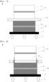
- FIG. 1 is a side view of a conventional all-solid-state battery 1 before pressing
- FIG. 2 is a side view of the conventional all-solid-state battery 1 after pressing.
- the conventional all-solid-state battery 1 is formed by pressing an electrode assembly configured such that a positive electrode 10 including a positive electrode active material layer 11 and a positive electrode current collector 12, a solid electrolyte layer 20, and a negative electrode 30 including a negative electrode active material layer 31 and a negative electrode current collector 32 are stacked.
- the electrode assembly is pressed in the state in which a pressing plate P is disposed at one surface of the electrode assembly.
- the pressing plate P is disposed at one surface of the electrode assembly, and pressing force F from the pressing plate P is applied in a direction toward the electrode assembly to reduce interfacial resistance between the positive electrode 10, the solid electrolyte layer 20, and the negative electrode 30.
- Pressing using the pressing plate P may be performed after the electrode assembly is received in a battery case and the battery case is hermetically sealed. Although the electrode assembly may be pressed even in a state of not being received in the battery case, there is a risk of the electrode assembly shaking when the electrode assembly is received in the battery case.
- the electrode assembly it is preferable for the electrode assembly to be pressed after hermetic sealing of the battery case in order to prevent contact between the sulfide-based solid electrolyte and moisture.
- the loading amount of an electrode active material of the all-solid-state battery 1 is not large, and therefore, when the all-solid-state battery 1 is pressed after being received in the battery case, damage to the battery case or damage to the electrode assembly is not great.
- the loading amount of the electrode active material has been increased in order to develop high-capacity, high-density all-solid-state batteries, whereby the thickness of the positive electrode 10 and/or the negative electrode 30 has gradually increased, and therefore the step between the positive electrode 10, the solid electrolyte layer 20, and the negative electrode 30 has been gradually enlarged. As the step is enlarged, the solid electrolyte layer 20 is damaged, whereby a damaged portion C is formed, as shown in FIG. 2 .
- the portion of the solid electrolyte layer 20, in which the damaged portion C is formed, between the positive electrode 10 and the negative electrode 30 that is necessary to prevent short circuit between the positive electrode 10 and the negative electrode 30 may be damaged. Due to the damaged portion C, short circuit may occur in the all-solid-state battery 1, whereby charging and discharging of the all-solid-state battery may not be possible. In severe cases, ignition or explosion of the all-solid-state battery may occur during driving thereof.
- the thickness of the solid electrolyte layer has been gradually reduced in order to improve density and performance of the all-solid-state battery, and therefore a possibility of damage to the solid electrolyte layer has further increased.
- the width of an electrode is changed in order to prevent collapse of an outer edge portion of an electrode layer or to prevent the electrode layer from tearing a solid electrolyte layer during pressing, and an electrode having a non-uniform shape, in which the outer edge portion of the electrode layer is thicker than a central portion of the electrode layer, is pressed in order to increase utilization of the electrode layer; however, uniform pressing of a high-capacity, high-density all-solid-state battery in order to prevent distortion of an electrode is not considered.
- Patent Document 1 Japanese Registered Patent Publication No. 5929748 (2016.05.13 )
- the present invention has been made in view of the above problems, and it is an object of the present invention to prevent short circuit between a positive electrode and a negative electrode of an all-solid-state battery while uniformly pressing an electrode assembly.
- an all-solid-state battery includes an electrode assembly including a positive electrode, a negative electrode, and a solid electrolyte layer disposed between the positive electrode and the negative electrode; and a battery case configured to receive the electrode assembly, wherein the thickness of the positive electrode is greater than the thickness of the negative electrode, and when the electrode assembly is pressed, the area of the electrode that directly faces a pressing portion is less than the area of the electrode that does not directly face the pressing portion.
- the electrode assembly may be pressed using a method of disposing a pressing plate at one surface of the electrode assembly and pushing the pressing plate.
- the electrode that directly faces the pressing portion may be the negative electrode, and the electrode that does not directly face the pressing portion may be the positive electrode.
- the positive electrode may have higher strength than the negative electrode.
- the strength means the limit of force at which an object is not permanently deformed or broken by load per unit area applied to the object.
- the area of the solid electrolyte layer may be equal to or greater than the area of an electrode having the largest area.
- the thickness of the solid electrolyte layer may be less than the thickness of the electrode that does not directly face the pressing portion.
- the thickness of the positive electrode may be two to five times thicker than the thickness of the negative electrode.
- the battery case may be a pouch-shaped secondary battery case.
- the all-solid-state battery may be a lithium plating/stripping all-solid-state battery.
- the present invention provides a method of manufacturing the all-solid-state battery described above, the method including S1) stacking a positive electrode, a solid electrolyte layer, and a negative electrode to form an electrode assembly and S2) pressing the electrode assembly in a direction from one of the positive and negative electrodes having a smaller area than the other to said the other having a larger area.
- Pores in the solid electrolyte layer may be removed in step S2) or may be removed before step S1).
- Step S2) may be performed after the electrode assembly is received in a battery case.
- Step S2) may be performed after the electrode assembly is received in the battery case and the battery case is vacuum sealed.
- the present invention provides a battery module or a battery pack including the all-solid-state battery.
- the present invention provides a device in which the all-solid-state battery is mounted.
- one or more constructions that do not conflict with each other may be selected and combined from among the above constructions.
- an all-solid-state battery according to the present invention is configured such that, when an electrode assembly is formed, short circuit between a positive electrode and a negative electrode is reduced while the electrode assembly is uniformly pressed, whereby initial production yield of the all-solid-state battery is increased and safety of the all-solid-state battery during driving thereof is improved.
- a thick positive electrode active material layer is provided, whereby the capacity of the battery is increased, and the strength of the positive electrode is also high, whereby distortion of or damage to the electrode assembly is prevented.
- An all-solid-state battery includes an electrode assembly including a positive electrode, a negative electrode, and a solid electrolyte layer disposed between the positive electrode and the negative electrode; and a battery case configured to receive the electrode assembly, wherein the thickness of the positive electrode is greater than the thickness of the negative electrode, and when the electrode assembly is pressed, the area of the electrode that directly faces a pressing portion is less than the area of the electrode that does not directly face the pressing portion.
- FIG. 3 is a side view of an all-solid-state battery 100 according to a first type of the present invention before pressing
- FIG. 4 is a side view of the all-solid-state battery 100 according to the first type of the present invention after pressing.
- an electrode assembly according to the present invention may include a plurality of positive electrodes 110, a plurality of solid electrolyte layers 120, and a plurality of negative electrodes 130, and the electrode assembly may be received in a battery case. This equally applies to FIGS. 5 and 6 .
- the all-solid-state battery 100 includes an electrode assembly, which includes a positive electrode 110 including a positive electrode active material layer 111 and a positive electrode current collector 112, a solid electrolyte layer 120, and a negative electrode 130 including a negative electrode active material layer 131 and a negative electrode current collector 132, and a battery case configured to receive the electrode assembly.
- an electrode assembly which includes a positive electrode 110 including a positive electrode active material layer 111 and a positive electrode current collector 112, a solid electrolyte layer 120, and a negative electrode 130 including a negative electrode active material layer 131 and a negative electrode current collector 132, and a battery case configured to receive the electrode assembly.
- the positive electrode 110 may be manufactured by applying a positive electrode mixture of a positive electrode active material constituted by positive electrode active material particles, a conductive agent, and a binder to the positive electrode current collector 112 to form the positive electrode active material layer 111.
- a filler may be further added to the positive electrode mixture as needed.
- the positive electrode current collector 112 is manufactured so as to have a thickness of 3 ⁇ m to 500 ⁇ m.
- the positive electrode current collector 112 is not particularly restricted as long as the positive electrode current collector exhibits high conductivity while the positive electrode current collector does not induce any chemical change in a battery to which the positive electrode current collector is applied.
- the positive electrode current collector may be made of stainless steel, aluminum, nickel, or titanium.
- the positive electrode current collector may be made of aluminum or stainless steel, the surface of which is treated with carbon, nickel, titanium, or silver.
- aluminum may be used.
- the current collector may have a micro-scale uneven pattern formed on the surface thereof so as to increase adhesive force of the positive electrode active material.
- the current collector may be configured in any of various forms, such as a film, a sheet, a foil, a net, a porous body, a foam body, and a non-woven fabric body.
- the positive electrode active material used in the present invention to use a metal oxide including lithium or to include the same in order to deposit lithium on one surface of the negative electrode 130.
- the positive electrode active material layer 111 may be thicker than the positive electrode current collector 112. As an example, the positive electrode active material layer 111 may be formed so as to have a thickness of 10 ⁇ m to 700 ⁇ m.
- the conductive agent is generally added so that the conductive agent accounts for 0.1 weight% to 30 weight% based on the total weight of the compound including the positive electrode active material.
- the conductive agent is not particularly restricted as long as the conductive agent exhibits conductivity without inducing any chemical change in a battery to which the conductive agent is applied.
- graphite such as natural graphite or artificial graphite
- carbon black such as carbon black, acetylene black, Ketjen black, channel black, furnace black, lamp black, or thermal black
- conductive fiber such as carbon fiber or metallic fiber
- metallic powder such as carbon fluoride powder, aluminum powder, or nickel powder
- conductive whisker such as zinc oxide or potassium titanate
- a conductive metal oxide such as titanium oxide
- a conductive material such as a polyphenylene derivative
- the binder which is included in the positive electrode 110, is a component assisting in binding between the active material and the conductive agent and in binding with the current collector.
- the binder is generally added in an amount of 0.1 to 30 weight% based on the total weight of the mixture including the positive electrode active material.
- binder there may be used polyvinylidene fluoride, polyvinyl alcohol, carboxymethylcellulose (CMC), starch, hydroxypropylcellulose, regenerated cellulose, polyvinylpyrrolidone, tetrafluoroethylene, polyethylene, polypropylene, ethylene-propylene-diene terpolymer (EPDM), sulfonated EPDM, styrene butadiene rubber, fluoro rubber, and various copolymers.
- CMC carboxymethylcellulose
- EPDM ethylene-propylene-diene terpolymer
- EPDM ethylene-propylene-diene terpolymer
- EPDM ethylene-propylene-diene terpolymer
- sulfonated EPDM styrene butadiene rubber
- fluoro rubber fluoro rubber
- An organic solid electrolyte or an inorganic solid electrolyte may be used for the solid electrolyte layer 120.
- the present invention is not limited thereto.
- a polyethylene derivative, a polyethylene oxide derivative, a polypropylene oxide derivative, a phosphoric acid ester polymer, poly agitation lysine, polyester sulfide, polyvinyl alcohol, polyvinylidene fluoride, or a polymer containing an ionic dissociation group may be used as the organic solid electrolyte.
- the inorganic solid electrolyte may be a sulfide-based solid electrolyte or an oxide-based solid electrolyte.
- a nitride or halide of Li such as Li 6.25 La 3 Zr 2 A 10.25 O 12 , Li 3 PO 4 , Li 3 +xPO 4 -xN x (LiPON), Li 3 N, LiI, Li 5 NI 2 , Li 3 N-LiI-LiOH, LiSiO 4 , LiSiO 4 -LiI-LiOH, Li 2 SiS 3 , Li 4 SiO 4 , or Li 4 SiO 4 -LiI-LiOH, may be used as the oxide-based solid electrolyte.
- the sulfide-based solid electrolyte is not particularly restricted, and all known sulfide-based materials used in the field of lithium batteries may be employed. Products on the market may be used as the sulfide-based materials, or amorphous sulfide-based materials may be crystallized to manufacture the sulfide-based materials. For example, a crystalline sulfide-based solid electrolyte, an amorphous sulfide-based solid electrolyte, or a mixture thereof may be used as the sulfide-based solid electrolyte.
- a sulfur-halogen compound, a sulfur-germanium compound, and a sulfur-silicon compound as examples of available composite compounds.
- a sulfide such as SiS 2 , GeS 2 , or B 2 S 3 , may be included, and Li 3 PO 4 , halogen, or a halogen compound may be added.
- a sulfide-based electrolyte capable of implementing a lithium ion conductivity of 10 -4 S/cm or more is used.
- Li 6 PS 5 Cl LPSCl
- Thio-LISICON Li 3.25 Ge 0.25 P 0.75 S 4
- Li 2 S-P 2 S 5 -LiCl Li 2 S-SiS 2 , LiI-Li 2 S-SiS 2 , LiI-Li 2 S-P 2 S 5 , LiI-Li 2 S-P 2 O 5 , LiI-Li 3 PO 4 -P 2 S 5 , Li 2 S-P 2 S 5 , Li 3 PS 4 , Li 7 P 3 S 11 , LiI-Li 2 S-B 2 S 3 , Li 3 PO 4 -Li 2 S-Si 2 S, Li 3 PO 4 -Li 2 S-SiS 2 , LiPO 4 -Li 2 S-SiS, Li 10 GeP 2 S 12 , Li 9.54 Si 1.74 P 1.44 S 11.7 Cl 0.3 , and Li 7 P 3 S 11 are included.
- a coating layer configured to induce formation of lithium dendrites may be provided on the surface of the solid electrolyte layer 120 that faces the negative electrode 130.
- the coating layer may include a metal in order to improve electrical conductivity and ionic conductivity.
- the kind of the metal is not limited as long as the metal enables lithium dendrites to be formed between the coating layer and the negative electrode 130 while improving performance of the negative electrode 130.
- the metal may be lithiophilic so as to induce lithium dendrites to be formed between the coating layer and the negative electrode 130.
- the lithiophilic metal may be disposed at the surface of the coating layer that faces the negative electrode 130 such that lithium dendrites do not grow in a direction toward the solid electrolyte layer 120.
- lithium plating is performed on the lithiophilic metal, whereby a lithium nucleus is formed, and lithium dendrites grow from the lithium nucleus at only the coating layer.
- At least one of a metal and a metal oxide may be selected as the lithiophilic material.
- the metal may be gold (Au), silver (Ag), platinum (Pt), zinc (Zn), silicon (Si), or magnesium (Mg)
- the metal oxide may be copper oxide, zinc oxide, or cobalt oxide, which is a nonmetal.
- a method of forming the coating layer is not particularly restricted.
- the coating layer may be formed by immersing, spin coating, dip coating, spray coating, doctor blade coating, solution casting, drop coating, physical vapor deposition (PVD), or chemical vapor deposition (CVD).
- the negative electrode 130 according to the first type of the present invention may include a negative electrode active material layer 131 and a negative electrode current collector 132.
- the negative electrode active material layer 131 may be formed by applying a negative electrode active material to at least one surface of the negative electrode current collector 132 and drying the negative electrode active material.
- the negative electrode active material used for the negative electrode active material layer 131 for example, there may be used carbon, such as a non-graphitizing carbon or a graphite-based carbon; a metal composite oxide, such as Li x Fe 2 O 3 (0 ⁇ x ⁇ 1), Li x WO 2 (0 ⁇ x ⁇ 1), Sn x Me 1-x Me' y O z (Me: Mn, Fe, Pb, Ge; Me': Al, B, P, Si, Group 1, 2, and 3 elements of the periodic table, halogen; 0 ⁇ x ⁇ 1; 1 ⁇ y ⁇ 3; 1 ⁇ z ⁇ 8); lithium metal; a lithium alloy; a silicon-based alloy; a tin-based alloy; a metal oxide, such as SnO, SnO 2 , PbO, PbO 2 , Pb 2 O 3 , Pb 3 O 4 , Sb 2 O 3 , Sb 2 O 4 , Sb 2 O 5 , GeO, GeO 2 , Bi 2 O 3 , Bi 2 O
- the negative electrode current collector 132 may generally be manufactured so as to have a thickness of 3 ⁇ m to 500 ⁇ m.
- the negative electrode current collector 132 is not particularly restricted as long as the negative electrode current collector exhibits conductivity while the negative electrode current collector does not induce any chemical change in a battery to which the negative electrode current collector is applied.
- the negative electrode current collector may be made of copper, stainless steel, aluminum, nickel, titanium, or sintered carbon.
- the negative electrode current collector may be made of copper or stainless steel, the surface of which is treated with carbon, nickel, titanium, or silver, or an aluminum-cadmium alloy.
- the negative electrode current collector may have a micro-scale uneven pattern formed on the surface thereof so as to increase binding force of the negative electrode active material, in the same manner as the positive electrode current collector 112.
- the negative electrode current collector may be configured in any of various forms, such as a film, a sheet, a foil, a net, a porous body, a foam body, and a non-woven fabric body.
- the battery case may be a pouch-shaped battery case.
- the thickness of an aluminum laminate sheet of the pouch-shaped battery case may be adjusted in order to obtain a high-capacity, high-density all-solid-state battery and to form various shapes of all-solid-state batteries.
- the laminate sheet may include an outer resin layer, a metal layer including an aluminum layer, and an inner sealant layer.
- the battery case is made of a laminate sheet, as described above, it is possible to press the electrode assembly even after the electrode assembly is received in the battery case, and to reduce a possibility of the positive electrode 110, the solid electrolyte layer 120, and the negative electrode 130 of the electrode assembly reacting with an external material.
- the electrode assembly it is preferable for the electrode assembly to be pressed after the electrode assembly is received in the battery case and the battery case is hermetically sealed.
- the thickness a of the positive electrode may be greater than the thickness b of the negative electrode, and when the electrode assembly is pressed, the area of the electrode that directly faces a pressing portion, which is a portion configured to perform pressing, may be less than the area of the electrode that does not face the pressing portion.
- the electrode that directly faces the pressing portion may be the negative electrode 130, and the electrode that does not directly face the pressing portion may be the positive electrode 110. That is, the positive electrode 110 may have a larger thickness and a larger area than the negative electrode 130.
- the thickness a of the positive electrode is large, as described above, strain of the positive electrode 110 that does not directly face the pressing portion is reduced, compared to a positive electrode 110 having a small thickness.
- the negative electrode 130 that directly faces the pressing portion may be deformed by the pressing portion, since the negative electrode 130 directly faces the pressing portion; however, a flat pressing plate P, as the pressing portion, faces the negative electrode 130, and therefore the shape of the negative electrode 130 may be maintained uniform by the pressing plate P.
- the thickness a of the positive electrode may be two to five times thicker than the thickness b of the negative electrode. If the thickness a of the positive electrode is too small, an all-solid-state battery having desired performance may not be obtained, and there is a high possibility of the positive electrode 110 of the electrode assembly being deformed. If the thickness a of the positive electrode is too large, the positive electrode 110 may not be efficiently operated.
- Pressing the electrode assembly may entail disposing the pressing plate P at one surface of the negative electrode 130 of the electrode assembly and pushing the pressing plate P in a direction from the pressing plate P toward the negative electrode 130.
- a pressing force F of higher than 50 MPa to lower than 1000 MPa may be applied to the all-solid-state battery for 1 minute or more, although the pressing force may be changed depending on the kind of the positive electrode 110, the solid electrolyte layer 120, and the negative electrode 130.
- Warm isostatic pressing is a process of simultaneously applying isostatic pressure to the stack at high temperature in order to process the stack.
- gas such as argon
- Cold isostatic pressing is a method of placing the stack in a mold having low shape resistance, such as a rubber bag, in a hermetically sealed state and applying uniform non-directional pressure to the surface of the stack using hydraulic pressure. It is preferable to use cold isostatic pressing, which has the lowest reactivity with a medium, although all isostatic pressing methods may be used for the all-solid-state battery according to the present invention.
- the positive electrode 110 may be made of a material that exhibits higher strength than the negative electrode 130.
- the positive electrode 110 is made of a material that exhibits higher strength than the negative electrode 130, a possibility of deformation is reduced, compared to the negative electrode 130, and the shape of the positive electrode 110, which occupies the overall part of the electrode assembly, is maintained, whereby a possibility of deformation of the electrode assembly is reduced. Therefore, it is preferable for the negative electrode 130 to be made of a material other than graphite.
- the pressing force F is applied to the positive electrode 110 from the negative electrode 130 via the solid electrolyte layer 120 in the pressing direction, whereby the solid electrolyte layer 120 disposed in contact with one surface of the positive electrode 110, the area of which is relatively large, is not damaged by the pressing force F.
- a damaged portion C may be formed at the portion of the solid electrolyte layer at which the negative electrode 130 and the positive electrode 110 do not contact each other. Consequently, a possibility of short circuit occurring between the positive electrode 110 and the negative electrode 130 due to pressing described above is reduced.
- pressing is mainly performed to reduce interfacial resistance of the electrode assembly, as described above, pressing may also be performed due to swelling of the all-solid-state battery caused as the result of use of the all-solid-state battery.
- the solid electrolyte layer 120 may be damaged due to contact between the electrode assembly and the battery case in the all-solid-state battery or external impact. Since the area of the positive electrode 110 is greater than the area of the negative electrode 130, however, a possibility of short circuit occurring in the electrode assembly is reduced even though the solid electrolyte layer 120 is damaged.
- the area of the solid electrolyte layer 120 may be equal to the area of the positive electrode 110, or may be greater than the area of the positive electrode 110.
- the area of the solid electrolyte layer 120 is equal to the area of the positive electrode 10
- the solid electrolyte layer 120 may serve to protect one surface of the positive electrode 110.
- the solid electrolyte layer 120 may serve to prevent contact between the portion at which the lithium layer is formed and the positive electrode 110.
- the thickness of the solid electrolyte layer 120 may be less than the thickness of the positive electrode 110. Since the solid electrolyte layer 120 faces the positive electrode 110, it is possible to prevent short circuit of the electrode assembly even though a portion of the solid electrolyte layer is damaged, and therefore it does not matter if opposite ends of the solid electrolyte layer are damaged. Consequently, the solid electrolyte layer 120 may have the minimum thickness sufficient to electrically isolate the positive electrode 110 and the negative electrode 130 from each other at the portion of the solid electrolyte layer that directly faces the positive electrode 110 and the negative electrode 130. As an example, the thickness of the solid electrolyte layer 120 may be 3 ⁇ m or more. If the solid electrolyte layer 120 is too thick, however, ionic conductivity is reduced, whereby performance of the battery is lowered. Consequently, it is preferable for the thickness of the solid electrolyte layer 120 to be small.
- FIG. 5 is a side view of an all-solid-state battery 200 according to a second type of the present invention before pressing
- FIG. 6 is a side view of the all-solid-state battery 200 according to the second type of the present invention after pressing.
- a negative electrode current collector 232 alone without a separate negative electrode active material layer or lithium metal may be used as a negative electrode 230, unlike FIGS. 3 and 4 .
- lithium ions of a positive electrode active material layer 211 are deposited on the negative electrode 230 to form a lithium layer 240 through a lithium plating/stripping mechanism during charging and discharging.
- a metal oxide including lithium may be used as a positive electrode active material of the positive electrode active material layer 211.
- a solid electrolyte layer 220 includes a lithiophilic metal and/or a lithiophilic metal oxide in a coating layer such that the lithium layer 240 does not grow in a direction toward the solid electrolyte layer 220.
- the coating layer may have a thickness of 5 nm to 20 ⁇ m. The reason for this is that, if the coating layer is too thick, ionic conductivity of the negative electrode may be reduced, and if the coating layer is too thin, it is difficult for the coating layer to prevent damage to the solid electrolyte layer 220 due to lithium dendrites.
- the thickness of the coating layer may vary depending on the content of metal in the coating layer and/or whether a high molecular weight polymer having ionic conductivity is added. It is preferable for the coating layer to have a thin film thickness, since the coating layer has no or low ionic conductivity.
- the lithium layer 240 is deposited on the negative electrode current collector 232.
- the lithium layer 240 is charged under constant current/constant voltage (CC/CV) conditions, and the thickness of the lithium layer may vary depending on the amount of lithium formed in the battery, charging and discharging speed, and charging and discharging time.
- CC/CV constant current/constant voltage
- the area of the negative electrode 230 it is preferable for the area of the negative electrode 230 to be 50% to 99% of the area of a positive electrode 210. If the area of the negative electrode 230 is less than 50% of the area of the positive electrode 210, an initial short circuit occurrence rate is reduced even though the edge of the solid electrolyte layer 220 is damaged; however, a relatively large amount of lithium is nonuniformly deposited on the edge of the negative electrode current collector 232 during charging, whereby the battery may not be normally operated. If the area of the negative electrode 230 is greater than 99% of the area of the positive electrode 210, on the other hand, a damaged portion of the solid electrolyte layer 220 may come into contact with the negative electrode current collector 232, whereby initial short circuit may occur.
- the above-mentioned area ratio is an example, and the area ratio of the negative electrode 230 to the positive electrode 210 may vary depending on the area of each of the negative electrode 230 and the positive electrode 210. At this time, the area of each of the negative electrode 230 and the positive electrode 210 must have a minimum tolerance of 1 mm or more in width and length.
- the lithium layer 240 may be formed so as to be larger than the area of the negative electrode 230. Since the area of the positive electrode 210 is greater than the area of the negative electrode 230, however, the lithium layer 240 may be smaller than the area of the positive electrode 210 or the area of the solid electrolyte layer 220.
- the all-solid-state battery 200 according to the second type of the present invention may have high density and high performance.
- the negative electrode 230 may have a thin film thickness
- the solid electrolyte layer 220 may also be formed so as to have only a thickness for minimum insulation due to the thickness difference between the positive electrode 210 and the negative electrode 230, whereby it is possible to obtain a high-density all-solid-state battery configured such that the overall thickness of the all-solid-state battery 200 is not large while the thickness of the positive electrode active material layer 211 related to capacity of the electrode is large.
- the solid electrolyte layer 220 may be formed so as to be thin, and a possibility of short circuit of the electrode assembly is reduced.
- an all-solid-state battery manufacturing method includes S1) a step of stacking a positive electrode, a solid electrolyte layer, and a negative electrode to form an electrode assembly and S2) a step of pressing the electrode assembly in a direction from an electrode having a small area, which is one of the positive electrode and the negative electrode, to an electrode having a large area.
- the thickness and the area of the positive electrode may be greater than the thickness and the area of the negative electrode.
- the electrode assembly may be pressed in a direction from the negative electrode to the positive electrode in order to reduce interfacial resistance of the electrode assembly.
- Pores in the solid electrolyte layer may be removed at the time of pressing in step S2), or may be removed before step S1). The reason for this is that it is necessary to prevent distortion or deformation of the electrode assembly due to operation of the all-solid-state battery or formation of a lithium layer.
- Step S2) may be performed after the electrode assembly is received in a battery case.
- the reason for this is that it is necessary to use a material that sensitively reacts to an external material for the electrode assembly, as in the case in which lithium is used for the negative electrode of the electrode assembly or a sulfide-based solid electrolyte is used for the solid electrolyte layer, or to prevent damage to or deformation of the electrode assembly.
- the electrode assembly in the case in which a material that sensitively reacts to an external material is used for the electrode assembly, it is preferable for the electrode assembly to be pressed after the electrode assembly is received in the battery case and the battery case is vacuum sealed.
- NCM811 LiNi 0.8 Co 0.1 Mn 0.1 O 2
- argyrodite Li 6 PS 5 Cl
- carbon as a conductive agent
- PTFE as a binder
- the positive electrode slurry was applied to an aluminum current collector having a thickness of 14 ⁇ m by doctor blade coating, and was dried in a vacuum state at 100°C for 12 hours to manufacture a positive electrode having a capacity of 6 mAh/cm 2 and a thickness of about 150 ⁇ m.
- Argyrodite (Li 6 PS 5 Cl), as a solid electrolyte, and PTFE, as a binder, were dispersed in anisole in a weight ratio of 95:5, and were stirred to manufacture a solid electrolyte layer slurry.
- the solid electrolyte layer slurry was applied to a PET release film by coating, and was dried in a vacuum state at 100°C for 12 hours to form a solid electrolyte layer.
- a lithium current collector having a thickness of 50 ⁇ m was used as the negative electrode.
- each of the positive electrode and the solid electrolyte layer was punched to an area of 2 cm ⁇ 2 cm, and the negative electrode was punched to an area of 1.8 cm ⁇ 1.8 cm.
- the positive electrode, the solid electrolyte layer, and the negative electrode are stacked in the stated order to manufacture a battery.
- the manufactured battery was pressed at a pressure of 500 MPa for 10 minutes through CIP in the state in which an SUS plate was located under the surface of the positive electrode.
- a battery was manufactured and evaluated in the same manner as in Example 1 except that a nickel current collector (10 ⁇ m) having 30 nm of silver deposited thereon was used as a negative electrode.
- a battery was manufactured and evaluated in the same manner as in Example 1 except that a positive electrode had a capacity of 4 mAh/cm 2 and a thickness of about 100 ⁇ m, the positive electrode was punched to an area of 1.8 cm ⁇ 1.8 cm, each of a negative electrode and a solid electrolyte layer was punched to an area of 2 cm ⁇ 2 cm, and the positive electrode, the solid electrolyte layer, and the negative electrode were assembled in order to manufacture the battery.
- a battery was manufactured and evaluated in the same manner as in Comparative Example 1 except that a positive electrode, a solid electrolyte layer, and a negative electrode were prepared in order to manufacture the battery, as in Comparative Example 1, and CIP was performed in the state in which an SUS plate was disposed on the surface of the positive electrode.
- a battery was manufactured and evaluated in the same manner as in Comparative Example 1 except that a positive electrode had a capacity of 6 mAh/cm 2 .
- a battery was manufactured and evaluated in the same manner as in Comparative Example 3 except that a nickel current collector (10 ⁇ m) having 30 nm of silver deposited thereon was used as a negative electrode.
- a battery was manufactured and evaluated in the same manner as in Comparative Example 4 except that each of a positive electrode and a solid electrolyte layer was punched to an area of 2 cm ⁇ 2 cm, a negative electrode was punched to an area of 1 cm ⁇ 1 cm, and the positive electrode, the solid electrolyte layer, and the negative electrode were assembled in order to manufacture the battery.
- a battery was manufactured and evaluated in the same manner as in Comparative Example 4 except that each of a positive electrode and a solid electrolyte layer was punched to an area of 2 cm ⁇ 2 cm, a negative electrode was punched to an area of 1.9 cm ⁇ 1.9 cm, and the positive electrode, the solid electrolyte layer, and the negative electrode were assembled in order to manufacture the battery.
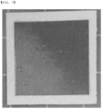
- FIG. 7 is a photograph of Comparative Example 3 before CIP pressing
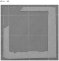
- FIG. 8 is a photograph of the electrode assembly of Comparative Example 3 after CIP pressing
- FIG. 9 is a photograph of the outer edge of the damaged solid electrolyte layer of Comparative Example 3 after CIP pressing
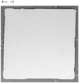
- FIG. 10 is a photograph of the surface of the positive electrode of Comparative Example 3 after CIP pressing
- FIG. 11 is a photograph of the surface of the residual solid electrolyte layer after damage of Comparative Example 3 after CIP pressing.
- the solid electrolyte layer which is not damaged before CIP, is broken along the area of the positive electrode.
- the measured OCV of each of the three manufactured batteries is less than 2.3 V, which is lower than normal OCV, which is 2.9 V.
- the present invention provides a battery module or a battery pack including the all-solid-state battery and a device including the battery pack.
- the battery module, the battery pack, and the device are well known in the art to which the present invention pertains, and thus a detailed description thereof will be omitted.
- the device may be a laptop computer, a netbook computer, a tablet PC, a mobile phone, an MP3 player, a wearable electronic device, a power tool, an electric vehicle (EV), a hybrid electric vehicle (HEV), a plug-in hybrid electric vehicle (PHEV), an electric bicycle (E-bike), an electric scooter (E-scooter), an electric golf cart, or an energy storage system.
- EV electric vehicle
- HEV hybrid electric vehicle
- PHEV plug-in hybrid electric vehicle
- E-bike electric bicycle
- E-scooter electric golf cart
- the present invention is not limited thereto.
- the present invention relates to an all-solid-state battery including an electrode assembly including a positive electrode, a negative electrode, and a solid electrolyte layer disposed between the positive electrode and the negative electrode and a battery case configured to receive the electrode assembly, wherein the thickness of the positive electrode is greater than the thickness of the negative electrode, and when the electrode assembly is pressed, the area of the electrode that directly faces a pressing portion is less than the area of the electrode that does not directly face the pressing portion, and a method of manufacturing the same, and therefore the present invention has industrial applicability.
Abstract
The present invention relates to an all-solid-state battery including an electrode assembly including a positive electrode, a negative electrode, and a solid electrolyte layer disposed between the positive electrode and the negative electrode and a battery case configured to receive the electrode assembly, wherein the thickness of the positive electrode is greater than the thickness of the negative electrode, and when the electrode assembly is pressed, the area of the electrode that directly faces a pressing portion is less than the area of the electrode that does not directly face the pressing portion, and a method of manufacturing the same.
Description
- This application claims the benefit of priority to
Korean Patent Application No. 2020-0145876 filed on November 4, 2020 - The present invention relates to an all-solid-state battery including a positive electrode having a larger area than a negative electrode and a method of manufacturing the same. More particularly, the present invention relates to an all-solid-state battery configured such that the thickness of a positive electrode is greater than the thickness of a negative electrode, and when an electrode assembly including the positive electrode, the negative electrode, and a solid electrolyte layer disposed between the positive electrode and the negative electrode is pressed, the area of the electrode that directly faces a pressing portion is less than the area of the electrode located at the surface opposite thereto, and a method of manufacturing the same.
- A lithium secondary battery, which has high energy density, a low self-discharge rate, and a long lifespan, is used for various high-capacity batteries. The lithium secondary battery has a problem in that a separator interposed between a positive electrode and a negative electrode is damaged or the volume of the battery is increased by lithium dendrites generated at the time of charging and discharging.
- In order to solve a safety-related problem caused by leakage of a liquid electrolyte or overheating, an all-solid-state battery is presented as an alternative. Unlike the lithium secondary battery, the all-solid-state battery has a solid electrolyte layer including a solid electrolyte, and the solid electrolyte layer is disposed between the positive electrode and the negative electrode so as to serve as a separator.
- Since the all-solid-state battery uses a solid electrolyte instead of a liquid electrolytic solution used in a conventional battery, evaporation of the electrolytic solution due to a change in temperature or leakage of the electrolytic solution due to external impact does not occur, whereby the all-solid-state battery is safe from explosion or fire. The region of the solid electrolyte that contacts the positive electrode or the negative electrode is limited due to characteristics of a solid, whereby formation of an interface between the positive electrode and the solid electrolyte layer and between the negative electrode and the solid electrolyte layer is not easy.
- In the case in which the area of contact between the positive electrode and the solid electrolyte layer and between the negative electrode and the solid electrolyte layer is small, electrical resistance is high and output is reduced, whereby interfacial resistance is reduced by pressing a unit cell including the solid electrolyte.
-
FIG. 1 is a side view of a conventional all-solid-state battery 1 before pressing, andFIG. 2 is a side view of the conventional all-solid-state battery 1 after pressing. - As shown in
FIGS. 1 and 2 , the conventional all-solid-state battery 1 is formed by pressing an electrode assembly configured such that apositive electrode 10 including a positive electrodeactive material layer 11 and a positiveelectrode current collector 12, asolid electrolyte layer 20, and anegative electrode 30 including a negative electrodeactive material layer 31 and a negativeelectrode current collector 32 are stacked. - In order to prevent distortion of the
positive electrode 10, thesolid electrolyte layer 20, and thenegative electrode 30 of the electrode assembly, the electrode assembly is pressed in the state in which a pressing plate P is disposed at one surface of the electrode assembly. - The pressing plate P is disposed at one surface of the electrode assembly, and pressing force F from the pressing plate P is applied in a direction toward the electrode assembly to reduce interfacial resistance between the
positive electrode 10, thesolid electrolyte layer 20, and thenegative electrode 30. - Pressing using the pressing plate P may be performed after the electrode assembly is received in a battery case and the battery case is hermetically sealed. Although the electrode assembly may be pressed even in a state of not being received in the battery case, there is a risk of the electrode assembly shaking when the electrode assembly is received in the battery case. In the case in which a sulfide-based solid electrolyte is used for the
solid electrolyte layer 20, it is preferable for the electrode assembly to be pressed after hermetic sealing of the battery case in order to prevent contact between the sulfide-based solid electrolyte and moisture. - Conventionally, the loading amount of an electrode active material of the all-solid-
state battery 1 is not large, and therefore, when the all-solid-state battery 1 is pressed after being received in the battery case, damage to the battery case or damage to the electrode assembly is not great. In recent years, however, the loading amount of the electrode active material has been increased in order to develop high-capacity, high-density all-solid-state batteries, whereby the thickness of thepositive electrode 10 and/or thenegative electrode 30 has gradually increased, and therefore the step between thepositive electrode 10, thesolid electrolyte layer 20, and thenegative electrode 30 has been gradually enlarged. As the step is enlarged, thesolid electrolyte layer 20 is damaged, whereby a damaged portion C is formed, as shown inFIG. 2 . - Even the portion of the
solid electrolyte layer 20, in which the damaged portion C is formed, between thepositive electrode 10 and thenegative electrode 30 that is necessary to prevent short circuit between thepositive electrode 10 and thenegative electrode 30 may be damaged. Due to the damaged portion C, short circuit may occur in the all-solid-state battery 1, whereby charging and discharging of the all-solid-state battery may not be possible. In severe cases, ignition or explosion of the all-solid-state battery may occur during driving thereof. - Furthermore, in recent years, the thickness of the solid electrolyte layer has been gradually reduced in order to improve density and performance of the all-solid-state battery, and therefore a possibility of damage to the solid electrolyte layer has further increased.
- In
Patent Document 1, the width of an electrode is changed in order to prevent collapse of an outer edge portion of an electrode layer or to prevent the electrode layer from tearing a solid electrolyte layer during pressing, and an electrode having a non-uniform shape, in which the outer edge portion of the electrode layer is thicker than a central portion of the electrode layer, is pressed in order to increase utilization of the electrode layer; however, uniform pressing of a high-capacity, high-density all-solid-state battery in order to prevent distortion of an electrode is not considered. - Therefore, there is a need to improve safety of an all-solid-state battery while improving performance and density thereof.
-
Japanese Registered Patent Publication No. 5929748 (2016.05.13 Patent Document 1") - The present invention has been made in view of the above problems, and it is an object of the present invention to prevent short circuit between a positive electrode and a negative electrode of an all-solid-state battery while uniformly pressing an electrode assembly.
- It is another object of the present invention to allow only a specific electrode to absorb pressure applied to the all-solid-state battery, thereby preventing distortion of the electrode and damage to the electrode and a solid electrolyte layer due to pressing.
- It is a further object of the present invention to prevent damage to an all-solid-state battery using an electrode having a large thickness, whereby it is possible to safely use a high-capacity, high-density all-solid-state battery.
- In order to accomplish the above objects, an all-solid-state battery according to the present invention includes an electrode assembly including a positive electrode, a negative electrode, and a solid electrolyte layer disposed between the positive electrode and the negative electrode; and a battery case configured to receive the electrode assembly, wherein the thickness of the positive electrode is greater than the thickness of the negative electrode, and when the electrode assembly is pressed, the area of the electrode that directly faces a pressing portion is less than the area of the electrode that does not directly face the pressing portion.
- At this time, the electrode assembly may be pressed using a method of disposing a pressing plate at one surface of the electrode assembly and pushing the pressing plate.
- The electrode that directly faces the pressing portion may be the negative electrode, and the electrode that does not directly face the pressing portion may be the positive electrode.
- The positive electrode may have higher strength than the negative electrode.
- The strength means the limit of force at which an object is not permanently deformed or broken by load per unit area applied to the object.
- The area of the solid electrolyte layer may be equal to or greater than the area of an electrode having the largest area.
- The thickness of the solid electrolyte layer may be less than the thickness of the electrode that does not directly face the pressing portion.
- At this time, the thickness of the positive electrode may be two to five times thicker than the thickness of the negative electrode.
- The battery case may be a pouch-shaped secondary battery case.
- The all-solid-state battery may be a lithium plating/stripping all-solid-state battery.
- The present invention provides a method of manufacturing the all-solid-state battery described above, the method including S1) stacking a positive electrode, a solid electrolyte layer, and a negative electrode to form an electrode assembly and S2) pressing the electrode assembly in a direction from one of the positive and negative electrodes having a smaller area than the other to said the other having a larger area.
- Pores in the solid electrolyte layer may be removed in step S2) or may be removed before step S1).
- Step S2) may be performed after the electrode assembly is received in a battery case.
- Step S2) may be performed after the electrode assembly is received in the battery case and the battery case is vacuum sealed.
- The present invention provides a battery module or a battery pack including the all-solid-state battery. In addition, the present invention provides a device in which the all-solid-state battery is mounted.
- In the present invention, one or more constructions that do not conflict with each other may be selected and combined from among the above constructions.
- As is apparent from the above description, an all-solid-state battery according to the present invention is configured such that, when an electrode assembly is formed, short circuit between a positive electrode and a negative electrode is reduced while the electrode assembly is uniformly pressed, whereby initial production yield of the all-solid-state battery is increased and safety of the all-solid-state battery during driving thereof is improved.
- In addition, a thick positive electrode active material layer is provided, whereby the capacity of the battery is increased, and the strength of the positive electrode is also high, whereby distortion of or damage to the electrode assembly is prevented.
- In addition, even though a relatively thin solid electrolyte layer is used, short circuit does not occur in the all-solid-state battery through a damaged portion of the solid electrolyte layer during pressing, whereby it is possible to obtain an all-solid-state battery having improved safety and performance.
-
-
FIG. 1 is a side view of a conventional all-solid-state battery before pressing. -
FIG. 2 is a side view of the conventional all-solid-state battery after pressing. -
FIG. 3 is a side view of an all-solid-state battery according to a first type of the present invention before pressing. -
FIG. 4 is a side view of the all-solid-state battery according to the first type of the present invention after pressing. -
FIG. 5 is a side view of an all-solid-state battery according to a second type of the present invention before pressing. -
FIG. 6 is a side view of the all-solid-state battery according to the second type of the present invention after pressing. -
FIG. 7 is a photograph of Comparative Example 3 before CIP pressing. -
FIG. 8 is a photograph of an electrode assembly of Comparative Example 3 after CIP pressing. -
FIG. 9 is a photograph of an outer edge of a damaged solid electrolyte layer of Comparative Example 3 after CIP pressing. -
FIG. 10 is a photograph of a surface of a positive electrode of Comparative Example 3 after CIP pressing. -
FIG. 11 is a photograph of a surface of a residual solid electrolyte layer after damage of Comparative Example 3 after CIP pressing. - Now, preferred embodiments of the present invention will be described in detail with reference to the accompanying drawings such that the preferred embodiments of the present invention can be easily implemented by a person having ordinary skill in the art to which the present invention pertains. In describing the principle of operation of the preferred embodiments of the present invention in detail, however, a detailed description of known functions and configurations incorporated herein will be omitted when the same may obscure the subject matter of the present invention.
- In addition, the same reference numbers will be used throughout the drawings to refer to parts that perform similar functions or operations. In the case in which one part is said to be connected to another part throughout the specification, not only may the one part be directly connected to the other part, but also, the one part may be indirectly connected to the other part via a further part. In addition, that a certain element is included does not mean that other elements are excluded, but means that such elements may be further included unless mentioned otherwise.
- In addition, a description to embody elements through limitation or addition may be applied to all inventions, unless particularly restricted, and does not limit a specific invention.
- Also, in the description of the invention and the claims of the present application, singular forms are intended to include plural forms unless mentioned otherwise.
- Also, in the description of the invention and the claims of the present application, "or" includes "and" unless mentioned otherwise. Therefore, "including A or B" means three cases, namely, the case including A, the case including B, and the case including A and B.
- In addition, all numeric ranges include the lowest value, the highest value, and all intermediate values therebetween unless the context clearly indicates otherwise.
- An all-solid-state battery according to the present invention includes an electrode assembly including a positive electrode, a negative electrode, and a solid electrolyte layer disposed between the positive electrode and the negative electrode; and a battery case configured to receive the electrode assembly, wherein the thickness of the positive electrode is greater than the thickness of the negative electrode, and when the electrode assembly is pressed, the area of the electrode that directly faces a pressing portion is less than the area of the electrode that does not directly face the pressing portion.
- The all-solid-state battery according to the present invention will be described with reference to
FIGS. 3 to 6 . -
FIG. 3 is a side view of an all-solid-state battery 100 according to a first type of the present invention before pressing, andFIG. 4 is a side view of the all-solid-state battery 100 according to the first type of the present invention after pressing. - In
FIGS. 3 and 4 , only onepositive electrode 110, onesolid electrolyte layer 120, and onenegative electrode 130 are shown for the convenience of description. However, an electrode assembly according to the present invention may include a plurality ofpositive electrodes 110, a plurality of solid electrolyte layers 120, and a plurality ofnegative electrodes 130, and the electrode assembly may be received in a battery case. This equally applies toFIGS. 5 and 6 . - The all-solid-
state battery 100 according to the first type of the present invention includes an electrode assembly, which includes apositive electrode 110 including a positive electrodeactive material layer 111 and a positive electrodecurrent collector 112, asolid electrolyte layer 120, and anegative electrode 130 including a negative electrodeactive material layer 131 and a negative electrodecurrent collector 132, and a battery case configured to receive the electrode assembly. - For example, the
positive electrode 110 may be manufactured by applying a positive electrode mixture of a positive electrode active material constituted by positive electrode active material particles, a conductive agent, and a binder to the positive electrodecurrent collector 112 to form the positive electrodeactive material layer 111. A filler may be further added to the positive electrode mixture as needed. - In general, the positive electrode
current collector 112 is manufactured so as to have a thickness of 3 µm to 500 µm. The positive electrodecurrent collector 112 is not particularly restricted as long as the positive electrode current collector exhibits high conductivity while the positive electrode current collector does not induce any chemical change in a battery to which the positive electrode current collector is applied. For example, the positive electrode current collector may be made of stainless steel, aluminum, nickel, or titanium. Alternatively, the positive electrode current collector may be made of aluminum or stainless steel, the surface of which is treated with carbon, nickel, titanium, or silver. Specifically, aluminum may be used. The current collector may have a micro-scale uneven pattern formed on the surface thereof so as to increase adhesive force of the positive electrode active material. The current collector may be configured in any of various forms, such as a film, a sheet, a foil, a net, a porous body, a foam body, and a non-woven fabric body. - In addition to the positive electrode active material particles, the positive electrode active material included in the positive electrode active material layer 111 may be constituted, for example, by a layered compound, such as lithium nickel oxide (LiNiO2), or a compound substituted with one or more transition metals; a lithium manganese oxide represented by the chemical formula Li1+xMn2-xO4 (where x = 0 to 0.33) or lithium manganese oxide, such as LiMnOs, LiMn2O3, or LiMnO2; lithium copper oxide (Li2CuO2); vanadium oxide, such as LiV3O8, LiV3O4, V2O5, or Cu2V2O7; an Ni-sited lithium nickel oxide represented by the chemical formula LiNi1-xMxO2 (where M = Co, Mn, Al, Cu, Fe, Mg, B, or Ga, and x = 0.01 to 0.3); a lithium manganese composite oxide represented by the chemical formula LiMn2-xMxO2 (where M = Co, Ni, Fe, Cr, Zn, or Ta, and x = 0.01 to 0.1) or the chemical formula Li2Mn3MO8 (where M = Fe, Co, Ni, Cu, or Zn); LiMn2O4 in which a portion of Li in the chemical formula is replaced by alkaline earth metal ions; a disulfide compound; or Fe2(MoO4)3. However, the present invention is not limited thereto.
- However, it is preferable for the positive electrode active material used in the present invention to use a metal oxide including lithium or to include the same in order to deposit lithium on one surface of the
negative electrode 130. - The positive electrode
active material layer 111 may be thicker than the positive electrodecurrent collector 112. As an example, the positive electrodeactive material layer 111 may be formed so as to have a thickness of 10 µm to 700 µm. - The conductive agent is generally added so that the conductive agent accounts for 0.1 weight% to 30 weight% based on the total weight of the compound including the positive electrode active material. The conductive agent is not particularly restricted as long as the conductive agent exhibits conductivity without inducing any chemical change in a battery to which the conductive agent is applied. For example, graphite, such as natural graphite or artificial graphite; carbon black, such as carbon black, acetylene black, Ketjen black, channel black, furnace black, lamp black, or thermal black; conductive fiber, such as carbon fiber or metallic fiber; metallic powder, such as carbon fluoride powder, aluminum powder, or nickel powder; conductive whisker, such as zinc oxide or potassium titanate; a conductive metal oxide, such as titanium oxide; or a conductive material, such as a polyphenylene derivative, may be used as the conductive agent.
- The binder, which is included in the
positive electrode 110, is a component assisting in binding between the active material and the conductive agent and in binding with the current collector. The binder is generally added in an amount of 0.1 to 30 weight% based on the total weight of the mixture including the positive electrode active material. As examples of the binder, there may be used polyvinylidene fluoride, polyvinyl alcohol, carboxymethylcellulose (CMC), starch, hydroxypropylcellulose, regenerated cellulose, polyvinylpyrrolidone, tetrafluoroethylene, polyethylene, polypropylene, ethylene-propylene-diene terpolymer (EPDM), sulfonated EPDM, styrene butadiene rubber, fluoro rubber, and various copolymers. - An organic solid electrolyte or an inorganic solid electrolyte may be used for the
solid electrolyte layer 120. However, the present invention is not limited thereto. - For example, a polyethylene derivative, a polyethylene oxide derivative, a polypropylene oxide derivative, a phosphoric acid ester polymer, poly agitation lysine, polyester sulfide, polyvinyl alcohol, polyvinylidene fluoride, or a polymer containing an ionic dissociation group may be used as the organic solid electrolyte.
- As an example, the inorganic solid electrolyte may be a sulfide-based solid electrolyte or an oxide-based solid electrolyte.
- For example, a nitride or halide of Li, such as Li6.25La3Zr2A10.25O12, Li3PO4, Li3+xPO4-xNx(LiPON), Li3N, LiI, Li5NI2, Li3N-LiI-LiOH, LiSiO4, LiSiO4-LiI-LiOH, Li2SiS3, Li4SiO4, or Li4SiO4-LiI-LiOH, may be used as the oxide-based solid electrolyte.
- In the present invention, the sulfide-based solid electrolyte is not particularly restricted, and all known sulfide-based materials used in the field of lithium batteries may be employed. Products on the market may be used as the sulfide-based materials, or amorphous sulfide-based materials may be crystallized to manufacture the sulfide-based materials. For example, a crystalline sulfide-based solid electrolyte, an amorphous sulfide-based solid electrolyte, or a mixture thereof may be used as the sulfide-based solid electrolyte. There are a sulfur-halogen compound, a sulfur-germanium compound, and a sulfur-silicon compound as examples of available composite compounds. Specifically, a sulfide, such as SiS2, GeS2, or B2S3, may be included, and Li3PO4, halogen, or a halogen compound may be added. Preferably, a sulfide-based electrolyte capable of implementing a lithium ion conductivity of 10-4 S/cm or more is used.
- Typically, Li6PS5Cl (LPSCl), Thio-LISICON (Li3.25Ge0.25P0.75S4), Li2S-P2S5-LiCl, Li2S-SiS2, LiI-Li2S-SiS2, LiI-Li2S-P2S5, LiI-Li2S-P2O5, LiI-Li3PO4-P2S5, Li2S-P2S5, Li3PS4, Li7P3S11, LiI-Li2S-B2S3, Li3PO4-Li2S-Si2S, Li3PO4-Li2S-SiS2, LiPO4-Li2S-SiS, Li10GeP2S12, Li9.54Si1.74P1.44S11.7Cl0.3, and Li7P3S11 are included.
- A coating layer configured to induce formation of lithium dendrites may be provided on the surface of the
solid electrolyte layer 120 that faces thenegative electrode 130. - The coating layer may include a metal in order to improve electrical conductivity and ionic conductivity. The kind of the metal is not limited as long as the metal enables lithium dendrites to be formed between the coating layer and the
negative electrode 130 while improving performance of thenegative electrode 130. At this time, the metal may be lithiophilic so as to induce lithium dendrites to be formed between the coating layer and thenegative electrode 130. - At this time, the lithiophilic metal may be disposed at the surface of the coating layer that faces the
negative electrode 130 such that lithium dendrites do not grow in a direction toward thesolid electrolyte layer 120. - In the case in which the lithiophilic metal is located at the coating layer, lithium plating is performed on the lithiophilic metal, whereby a lithium nucleus is formed, and lithium dendrites grow from the lithium nucleus at only the coating layer.
- At least one of a metal and a metal oxide may be selected as the lithiophilic material. For example, the metal may be gold (Au), silver (Ag), platinum (Pt), zinc (Zn), silicon (Si), or magnesium (Mg), and the metal oxide may be copper oxide, zinc oxide, or cobalt oxide, which is a nonmetal.
- A method of forming the coating layer is not particularly restricted. For example, the coating layer may be formed by immersing, spin coating, dip coating, spray coating, doctor blade coating, solution casting, drop coating, physical vapor deposition (PVD), or chemical vapor deposition (CVD).
- The
negative electrode 130 according to the first type of the present invention may include a negative electrodeactive material layer 131 and a negative electrodecurrent collector 132. - The negative electrode
active material layer 131 may be formed by applying a negative electrode active material to at least one surface of the negative electrodecurrent collector 132 and drying the negative electrode active material. - As the negative electrode active material used for the negative electrode
active material layer 131, for example, there may be used carbon, such as a non-graphitizing carbon or a graphite-based carbon; a metal composite oxide, such as LixFe2O3 (0≤x≤1), LixWO2 (0≤x≤1), SnxMe1-xMe'yOz (Me: Mn, Fe, Pb, Ge; Me': Al, B, P, Si,Group 1, 2, and 3 elements of the periodic table, halogen; 0<x≤1; 1≤y≤3; 1≤z≤8); lithium metal; a lithium alloy; a silicon-based alloy; a tin-based alloy; a metal oxide, such as SnO, SnO2, PbO, PbO2, Pb2O3, Pb3O4, Sb2O3, Sb2O4, Sb2O5, GeO, GeO2, Bi2O3, Bi2O4, or Bi2O5; a conductive polymer, such as polyacetylene; or a Li-Co-Ni-based material. - The negative electrode
current collector 132 may generally be manufactured so as to have a thickness of 3 µm to 500 µm. The negative electrodecurrent collector 132 is not particularly restricted as long as the negative electrode current collector exhibits conductivity while the negative electrode current collector does not induce any chemical change in a battery to which the negative electrode current collector is applied. For example, the negative electrode current collector may be made of copper, stainless steel, aluminum, nickel, titanium, or sintered carbon. Alternatively, the negative electrode current collector may be made of copper or stainless steel, the surface of which is treated with carbon, nickel, titanium, or silver, or an aluminum-cadmium alloy. In addition, the negative electrode current collector may have a micro-scale uneven pattern formed on the surface thereof so as to increase binding force of the negative electrode active material, in the same manner as the positive electrodecurrent collector 112. The negative electrode current collector may be configured in any of various forms, such as a film, a sheet, a foil, a net, a porous body, a foam body, and a non-woven fabric body. - The battery case may be a pouch-shaped battery case. The thickness of an aluminum laminate sheet of the pouch-shaped battery case may be adjusted in order to obtain a high-capacity, high-density all-solid-state battery and to form various shapes of all-solid-state batteries. At this time, the laminate sheet may include an outer resin layer, a metal layer including an aluminum layer, and an inner sealant layer.
- Since the battery case is made of a laminate sheet, as described above, it is possible to press the electrode assembly even after the electrode assembly is received in the battery case, and to reduce a possibility of the
positive electrode 110, thesolid electrolyte layer 120, and thenegative electrode 130 of the electrode assembly reacting with an external material. - Particularly, in the case in which lithium metal is used for the
negative electrode 130, there is a possibility of the lithium metal reacting with moisture. In the case in which the lithium metal is used for thenegative electrode 130, therefore, it is preferable for the electrode assembly to be pressed after the electrode assembly is received in the battery case and the battery case is hermetically sealed. - The thickness a of the positive electrode may be greater than the thickness b of the negative electrode, and when the electrode assembly is pressed, the area of the electrode that directly faces a pressing portion, which is a portion configured to perform pressing, may be less than the area of the electrode that does not face the pressing portion.
- At this time, the electrode that directly faces the pressing portion may be the
negative electrode 130, and the electrode that does not directly face the pressing portion may be thepositive electrode 110. That is, thepositive electrode 110 may have a larger thickness and a larger area than thenegative electrode 130. - In the case in which the thickness a of the positive electrode is large, as described above, strain of the
positive electrode 110 that does not directly face the pressing portion is reduced, compared to apositive electrode 110 having a small thickness. In contrast, thenegative electrode 130 that directly faces the pressing portion may be deformed by the pressing portion, since thenegative electrode 130 directly faces the pressing portion; however, a flat pressing plate P, as the pressing portion, faces thenegative electrode 130, and therefore the shape of thenegative electrode 130 may be maintained uniform by the pressing plate P. - At this time, the thickness a of the positive electrode may be two to five times thicker than the thickness b of the negative electrode. If the thickness a of the positive electrode is too small, an all-solid-state battery having desired performance may not be obtained, and there is a high possibility of the
positive electrode 110 of the electrode assembly being deformed. If the thickness a of the positive electrode is too large, thepositive electrode 110 may not be efficiently operated. - Pressing the electrode assembly may entail disposing the pressing plate P at one surface of the
negative electrode 130 of the electrode assembly and pushing the pressing plate P in a direction from the pressing plate P toward thenegative electrode 130. - At this time, a pressing force F of higher than 50 MPa to lower than 1000 MPa may be applied to the all-solid-state battery for 1 minute or more, although the pressing force may be changed depending on the kind of the
positive electrode 110, thesolid electrolyte layer 120, and thenegative electrode 130. - Pressing may be performed through warm isostatic pressing (WIP) or cold isostatic pressing (CIP). Warm isostatic pressing is a process of simultaneously applying isostatic pressure to the stack at high temperature in order to process the stack. In many cases, gas, such as argon, is generally used as a pressure medium. Cold isostatic pressing is a method of placing the stack in a mold having low shape resistance, such as a rubber bag, in a hermetically sealed state and applying uniform non-directional pressure to the surface of the stack using hydraulic pressure. It is preferable to use cold isostatic pressing, which has the lowest reactivity with a medium, although all isostatic pressing methods may be used for the all-solid-state battery according to the present invention.
- In the case in which the electrode assembly is pressed in one direction, as described above, it is possible to prevent distortion of the electrode assembly.
- Additionally, the
positive electrode 110 may be made of a material that exhibits higher strength than thenegative electrode 130. In the case in which thepositive electrode 110 is made of a material that exhibits higher strength than thenegative electrode 130, a possibility of deformation is reduced, compared to thenegative electrode 130, and the shape of thepositive electrode 110, which occupies the overall part of the electrode assembly, is maintained, whereby a possibility of deformation of the electrode assembly is reduced. Therefore, it is preferable for thenegative electrode 130 to be made of a material other than graphite. - At this time, in the case in which the area of the
positive electrode 110 is greater than the area of thenegative electrode 130, the pressing force F is applied to thepositive electrode 110 from thenegative electrode 130 via thesolid electrolyte layer 120 in the pressing direction, whereby thesolid electrolyte layer 120 disposed in contact with one surface of thepositive electrode 110, the area of which is relatively large, is not damaged by the pressing force F. - Even though the
solid electrolyte layer 120 is damaged, a damaged portion C may be formed at the portion of the solid electrolyte layer at which thenegative electrode 130 and thepositive electrode 110 do not contact each other. Consequently, a possibility of short circuit occurring between thepositive electrode 110 and thenegative electrode 130 due to pressing described above is reduced. - Although pressing is mainly performed to reduce interfacial resistance of the electrode assembly, as described above, pressing may also be performed due to swelling of the all-solid-state battery caused as the result of use of the all-solid-state battery. At this time, the
solid electrolyte layer 120 may be damaged due to contact between the electrode assembly and the battery case in the all-solid-state battery or external impact. Since the area of thepositive electrode 110 is greater than the area of thenegative electrode 130, however, a possibility of short circuit occurring in the electrode assembly is reduced even though thesolid electrolyte layer 120 is damaged. - At this time, the area of the
solid electrolyte layer 120 may be equal to the area of thepositive electrode 110, or may be greater than the area of thepositive electrode 110. In the case in which the area of thesolid electrolyte layer 120 is equal to the area of thepositive electrode 10, a possibility of thesolid electrolyte layer 120 being damaged by external impact is reduced, and it is possible to reduce manufacturing cost of the all-solid-state battery. Also, in the case in which the area of thesolid electrolyte layer 120 is greater than the area of thepositive electrode 110, thesolid electrolyte layer 120 may serve to protect one surface of thepositive electrode 110. Also, in the case in which a lithium layer is formed by lithium plating/stripping, thesolid electrolyte layer 120 may serve to prevent contact between the portion at which the lithium layer is formed and thepositive electrode 110. - The thickness of the
solid electrolyte layer 120 may be less than the thickness of thepositive electrode 110. Since thesolid electrolyte layer 120 faces thepositive electrode 110, it is possible to prevent short circuit of the electrode assembly even though a portion of the solid electrolyte layer is damaged, and therefore it does not matter if opposite ends of the solid electrolyte layer are damaged. Consequently, thesolid electrolyte layer 120 may have the minimum thickness sufficient to electrically isolate thepositive electrode 110 and thenegative electrode 130 from each other at the portion of the solid electrolyte layer that directly faces thepositive electrode 110 and thenegative electrode 130. As an example, the thickness of thesolid electrolyte layer 120 may be 3 µm or more. If thesolid electrolyte layer 120 is too thick, however, ionic conductivity is reduced, whereby performance of the battery is lowered. Consequently, it is preferable for the thickness of thesolid electrolyte layer 120 to be small. -
FIG. 5 is a side view of an all-solid-state battery 200 according to a second type of the present invention before pressing, andFIG. 6 is a side view of the all-solid-state battery 200 according to the second type of the present invention after pressing. - Hereinafter, only the difference from the first type will be mentioned.
- In the all-solid-
state battery 200 according to the second type of the present invention, a negative electrodecurrent collector 232 alone without a separate negative electrode active material layer or lithium metal may be used as anegative electrode 230, unlikeFIGS. 3 and 4 . In the all-solid-state battery 200 according to the second type, lithium ions of a positive electrodeactive material layer 211 are deposited on thenegative electrode 230 to form alithium layer 240 through a lithium plating/stripping mechanism during charging and discharging. To this end, a metal oxide including lithium may be used as a positive electrode active material of the positive electrodeactive material layer 211. - A
solid electrolyte layer 220 includes a lithiophilic metal and/or a lithiophilic metal oxide in a coating layer such that thelithium layer 240 does not grow in a direction toward thesolid electrolyte layer 220. - The coating layer may have a thickness of 5 nm to 20 µm. The reason for this is that, if the coating layer is too thick, ionic conductivity of the negative electrode may be reduced, and if the coating layer is too thin, it is difficult for the coating layer to prevent damage to the
solid electrolyte layer 220 due to lithium dendrites. The thickness of the coating layer may vary depending on the content of metal in the coating layer and/or whether a high molecular weight polymer having ionic conductivity is added. It is preferable for the coating layer to have a thin film thickness, since the coating layer has no or low ionic conductivity. - The
lithium layer 240 is deposited on the negative electrodecurrent collector 232. Thelithium layer 240 is charged under constant current/constant voltage (CC/CV) conditions, and the thickness of the lithium layer may vary depending on the amount of lithium formed in the battery, charging and discharging speed, and charging and discharging time. - At this time, it is preferable for the area of the
negative electrode 230 to be 50% to 99% of the area of apositive electrode 210. If the area of thenegative electrode 230 is less than 50% of the area of thepositive electrode 210, an initial short circuit occurrence rate is reduced even though the edge of thesolid electrolyte layer 220 is damaged; however, a relatively large amount of lithium is nonuniformly deposited on the edge of the negative electrodecurrent collector 232 during charging, whereby the battery may not be normally operated. If the area of thenegative electrode 230 is greater than 99% of the area of thepositive electrode 210, on the other hand, a damaged portion of thesolid electrolyte layer 220 may come into contact with the negative electrodecurrent collector 232, whereby initial short circuit may occur. The above-mentioned area ratio is an example, and the area ratio of thenegative electrode 230 to thepositive electrode 210 may vary depending on the area of each of thenegative electrode 230 and thepositive electrode 210. At this time, the area of each of thenegative electrode 230 and thepositive electrode 210 must have a minimum tolerance of 1 mm or more in width and length. - The
lithium layer 240 may be formed so as to be larger than the area of thenegative electrode 230. Since the area of thepositive electrode 210 is greater than the area of thenegative electrode 230, however, thelithium layer 240 may be smaller than the area of thepositive electrode 210 or the area of thesolid electrolyte layer 220. - Since the
negative electrode 230 can be formed so as to have a small thickness through lithium plating/stripping, as described above, the all-solid-state battery 200 according to the second type of the present invention may have high density and high performance. At this time, thenegative electrode 230 may have a thin film thickness, and thesolid electrolyte layer 220 may also be formed so as to have only a thickness for minimum insulation due to the thickness difference between thepositive electrode 210 and thenegative electrode 230, whereby it is possible to obtain a high-density all-solid-state battery configured such that the overall thickness of the all-solid-state battery 200 is not large while the thickness of the positive electrodeactive material layer 211 related to capacity of the electrode is large. - In addition, since the
lithium layer 240 is formed through lithium plating/stripping, as described above, formation of lithium dendrites at a non-desired portion is reduced, thesolid electrolyte layer 220 may be formed so as to be thin, and a possibility of short circuit of the electrode assembly is reduced. - In order to manufacture the all-solid-state battery described above, an all-solid-state battery manufacturing method according to the present invention includes S1) a step of stacking a positive electrode, a solid electrolyte layer, and a negative electrode to form an electrode assembly and S2) a step of pressing the electrode assembly in a direction from an electrode having a small area, which is one of the positive electrode and the negative electrode, to an electrode having a large area.
- As mentioned in the first type and the second type, the thickness and the area of the positive electrode may be greater than the thickness and the area of the negative electrode. At this time, the electrode assembly may be pressed in a direction from the negative electrode to the positive electrode in order to reduce interfacial resistance of the electrode assembly.
- Pores in the solid electrolyte layer may be removed at the time of pressing in step S2), or may be removed before step S1). The reason for this is that it is necessary to prevent distortion or deformation of the electrode assembly due to operation of the all-solid-state battery or formation of a lithium layer.
- Step S2) may be performed after the electrode assembly is received in a battery case. The reason for this is that it is necessary to use a material that sensitively reacts to an external material for the electrode assembly, as in the case in which lithium is used for the negative electrode of the electrode assembly or a sulfide-based solid electrolyte is used for the solid electrolyte layer, or to prevent damage to or deformation of the electrode assembly.
- Particularly, in the case in which a material that sensitively reacts to an external material is used for the electrode assembly, it is preferable for the electrode assembly to be pressed after the electrode assembly is received in the battery case and the battery case is vacuum sealed.
- Hereinafter, the present invention will be described based on Experimental Examples in which Examples according to the present invention and Comparative Examples according to the conventional art were compared with each other.
- Experiments were conducted on an all-solid-state battery including a positive electrode, a solid electrolyte layer, and a negative electrode as follows.
- NCM811 (LiNi0.8Co0.1Mn0.1O2), as a positive electrode active material, argyrodite (Li6PS5Cl), as a solid electrolyte, carbon, as a conductive agent, and PTFE, as a binder, were dispersed in anisole in a weight ratio of 77.5:19.5:1.5:1.5, and were stirred to manufacture a positive electrode slurry. The positive electrode slurry was applied to an aluminum current collector having a thickness of 14 µm by doctor blade coating, and was dried in a vacuum state at 100°C for 12 hours to manufacture a positive electrode having a capacity of 6 mAh/cm2 and a thickness of about 150 µm.
- Argyrodite (Li6PS5Cl), as a solid electrolyte, and PTFE, as a binder, were dispersed in anisole in a weight ratio of 95:5, and were stirred to manufacture a solid electrolyte layer slurry. The solid electrolyte layer slurry was applied to a PET release film by coating, and was dried in a vacuum state at 100°C for 12 hours to form a solid electrolyte layer.
- A lithium current collector having a thickness of 50 µm was used as the negative electrode.
- At this time, each of the positive electrode and the solid electrolyte layer was punched to an area of 2 cm × 2 cm, and the negative electrode was punched to an area of 1.8 cm × 1.8 cm. The positive electrode, the solid electrolyte layer, and the negative electrode are stacked in the stated order to manufacture a battery. The manufactured battery was pressed at a pressure of 500 MPa for 10 minutes through CIP in the state in which an SUS plate was located under the surface of the positive electrode.
- After assembly, OCV of the battery was measured to check a short circuit occurrence rate. In addition, a 0.05C charging/0.05C discharging experiment in a voltage range of 4.25 V to 3.0 V at 60°C was conducted on the battery. The results are shown in Table 1 below.
- A battery was manufactured and evaluated in the same manner as in Example 1 except that a nickel current collector (10 µm) having 30 nm of silver deposited thereon was used as a negative electrode.
- A battery was manufactured and evaluated in the same manner as in Example 1 except that a positive electrode had a capacity of 4 mAh/cm2 and a thickness of about 100 µm, the positive electrode was punched to an area of 1.8 cm × 1.8 cm, each of a negative electrode and a solid electrolyte layer was punched to an area of 2 cm × 2 cm, and the positive electrode, the solid electrolyte layer, and the negative electrode were assembled in order to manufacture the battery.
- A battery was manufactured and evaluated in the same manner as in Comparative Example 1 except that a positive electrode, a solid electrolyte layer, and a negative electrode were prepared in order to manufacture the battery, as in Comparative Example 1, and CIP was performed in the state in which an SUS plate was disposed on the surface of the positive electrode.
- A battery was manufactured and evaluated in the same manner as in Comparative Example 1 except that a positive electrode had a capacity of 6 mAh/cm2.
- A battery was manufactured and evaluated in the same manner as in Comparative Example 3 except that a nickel current collector (10 µm) having 30 nm of silver deposited thereon was used as a negative electrode.
- A battery was manufactured and evaluated in the same manner as in Comparative Example 4 except that each of a positive electrode and a solid electrolyte layer was punched to an area of 2 cm × 2 cm, a negative electrode was punched to an area of 1 cm × 1 cm, and the positive electrode, the solid electrolyte layer, and the negative electrode were assembled in order to manufacture the battery.
- A battery was manufactured and evaluated in the same manner as in Comparative Example 4 except that each of a positive electrode and a solid electrolyte layer was punched to an area of 2 cm × 2 cm, a negative electrode was punched to an area of 1.9 cm × 1.9 cm, and the positive electrode, the solid electrolyte layer, and the negative electrode were assembled in order to manufacture the battery.
[Table 1] OCV after assembly Occurrence of short circuit after assembly Discharge capacity (mAh/g) Example 1 2.9 0/3 195 Example 2 0.3 to 0.4 0/3 192 Comparative Example 1 2.9 1/3 201 Comparative Example 2 <2.3 3/3 - Comparative Example 3 <2.3 3/3 - Comparative Example 4 <0.2 3/3 - Comparative Example 5 0.3 to 0.4 0/3 Short circuit Comparative Example 6 <0.2 2/3 Short circuit - As can be seen from Table 1 above, for a battery having a small positive electrode capacity, as in Comparative Example 1, no short circuit easily occurs after assembly. However, it can be seen that, for Comparative Example 2, in which the SUS plate is located at the positive electrode, the area of which is small, when CIP is performed, the negative electrode and the solid electrolyte layer, each of which has low strength and a large area, are deformed in a state of wrapping the positive electrode, the area of which is small, whereby short circuit occurs. That is, it can be seen that it is good for the SUS plate to face an electrode having a large area or an electrode surface having high strength.
- However, in the case in which the positive electrode is manufactured so as to have a capacity of 6 mAh/cm2 even though the structure in which the SUS plate faces an electrode having a large area or an electrode surface having high strength is provided, CIP pressing must be performed in order to improve contact in the all-solid-state battery.
-
FIG. 7 is a photograph of Comparative Example 3 before CIP pressing,FIG. 8 is a photograph of the electrode assembly of Comparative Example 3 after CIP pressing,FIG. 9 is a photograph of the outer edge of the damaged solid electrolyte layer of Comparative Example 3 after CIP pressing,FIG. 10 is a photograph of the surface of the positive electrode of Comparative Example 3 after CIP pressing, andFIG. 11 is a photograph of the surface of the residual solid electrolyte layer after damage of Comparative Example 3 after CIP pressing. - As can be seen from
FIGS. 7 to 11 , when CIP pressing is performed, the solid electrolyte layer, which is not damaged before CIP, is broken along the area of the positive electrode. In addition, as the result of checking OCV of Comparative Example 3, the measured OCV of each of the three manufactured batteries is less than 2.3 V, which is lower than normal OCV, which is 2.9 V. - In addition, the present invention provides a battery module or a battery pack including the all-solid-state battery and a device including the battery pack. The battery module, the battery pack, and the device are well known in the art to which the present invention pertains, and thus a detailed description thereof will be omitted.
- For example, the device may be a laptop computer, a netbook computer, a tablet PC, a mobile phone, an MP3 player, a wearable electronic device, a power tool, an electric vehicle (EV), a hybrid electric vehicle (HEV), a plug-in hybrid electric vehicle (PHEV), an electric bicycle (E-bike), an electric scooter (E-scooter), an electric golf cart, or an energy storage system. However, the present invention is not limited thereto.
- Those skilled in the art to which the present invention pertains will appreciate that various applications and modifications are possible within the category of the present invention based on the above description.
-
- 1, 100, 200: All-solid-state batteries
- 10, 110, 210: Positive electrodes
- 11, 111, 211: Positive electrode active material layers
- 12, 112, 212: Positive electrode current collectors
- 20, 120, 220: Solid electrolyte layers
- 30, 130, 230: Negative electrodes
- 31, 131: Negative electrode active material layers
- 32, 132, 232: Negative electrode current collectors
- 40, 240: Lithium layers
- a: Thickness of positive electrode
- b: Thickness of negative electrode
- P: Pressing plate
- F: Pressing force
- C: Damaged portion
- The present invention relates to an all-solid-state battery including an electrode assembly including a positive electrode, a negative electrode, and a solid electrolyte layer disposed between the positive electrode and the negative electrode and a battery case configured to receive the electrode assembly, wherein the thickness of the positive electrode is greater than the thickness of the negative electrode, and when the electrode assembly is pressed, the area of the electrode that directly faces a pressing portion is less than the area of the electrode that does not directly face the pressing portion, and a method of manufacturing the same, and therefore the present invention has industrial applicability.
Claims (13)
- An all-solid-state battery comprising:an electrode assembly comprising a positive electrode, a negative electrode, and a solid electrolyte layer disposed between the positive electrode and the negative electrode; anda battery case configured to receive the electrode assembly,wherein a thickness of the positive electrode is greater than a thickness of the negative electrode, andwherein, when the electrode assembly is pressed, an area of an electrode that directly faces a pressing portion is less than an area of an electrode that does not directly face the pressing portion.
- The all-solid-state battery according to claim 1, wherein the electrode assembly is pressed using a method of disposing a pressing plate at one surface of the electrode assembly and pushing the pressing plate.
- The all-solid-state battery according to claim 1, whereinthe electrode that directly faces the pressing portion is the negative electrode, andthe electrode that does not directly face the pressing portion is the positive electrode.
- The all-solid-state battery according to claim 3, wherein the positive electrode has higher strength than the negative electrode.
- The all-solid-state battery according to claim 1, wherein an area of the solid electrolyte layer is equal to or greater than an area of an electrode having a largest area.
- The all-solid-state battery according to claim 1, wherein a thickness of the solid electrolyte layer is less than a thickness of the electrode that does not directly face the pressing portion.
- The all-solid-state battery according to claim 1, wherein a thickness of the positive electrode is two to five times thicker than a thickness of the negative electrode.
- The all-solid-state battery according to claim 1, wherein the battery case is a pouch-shaped secondary battery case.
- The all-solid-state battery according to claim 1, wherein the all-solid-state battery is a lithium plating/stripping all-solid-state battery.
- A method of manufacturing the all-solid-state battery according to any one of claims 1 to 9, the method comprising:S1) stacking a positive electrode, a solid electrolyte layer, and a negative electrode to form an electrode assembly; andS2) pressing the electrode assembly in a direction from one of the positive and negative electrodes having a smaller area than the other to said the other having a larger area.
- The method according to claim 10, wherein pores in the solid electrolyte layer are removed in step S2) or are removed before step S1).
- The method according to claim 10, wherein step S2) is performed after the electrode assembly is received in a battery case.
- The method according to claim 12, wherein step S2) is performed after the electrode assembly is received in the battery case and the battery case is vacuum sealed.
Applications Claiming Priority (2)
| Application Number | Priority Date | Filing Date | Title |
|---|---|---|---|
| KR1020200145876A KR20220060186A (en) | 2020-11-04 | 2020-11-04 | All solid-state battery having a positive electrode with larger area than the negative electrode and a method for manufacturing the same |
| PCT/KR2021/015684 WO2022098049A1 (en) | 2020-11-04 | 2021-11-02 | All-solid-state battery including positive electrode having wider area than negative electrode, and manufacturing method therefor |
Publications (1)
| Publication Number | Publication Date |
|---|---|
| EP4243153A1 true EP4243153A1 (en) | 2023-09-13 |
Family
ID=81458081
Family Applications (1)
| Application Number | Title | Priority Date | Filing Date |
|---|---|---|---|
| EP21889514.2A Pending EP4243153A1 (en) | 2020-11-04 | 2021-11-02 | All-solid-state battery including positive electrode having wider area than negative electrode, and manufacturing method therefor |
Country Status (6)
| Country | Link |
|---|---|
| US (1) | US20230411667A1 (en) |
| EP (1) | EP4243153A1 (en) |
| JP (1) | JP2023548177A (en) |
| KR (1) | KR20220060186A (en) |
| CN (1) | CN116569379A (en) |
| WO (1) | WO2022098049A1 (en) |
Family Cites Families (8)
| Publication number | Priority date | Publication date | Assignee | Title |
|---|---|---|---|---|
| US4228841A (en) | 1975-06-04 | 1980-10-21 | Panelfold Doors, Inc. | Extruded material folding door with panel lock |
| US20120177998A1 (en) * | 2009-10-05 | 2012-07-12 | Sumitomo Electric Industries, Ltd. | Nonaqueous electrolyte battery |
| JP5929748B2 (en) | 2012-12-27 | 2016-06-08 | トヨタ自動車株式会社 | Manufacturing method of all solid state battery |
| JP2015162353A (en) * | 2014-02-27 | 2015-09-07 | トヨタ自動車株式会社 | Method for manufacturing all-solid battery |
| JP6399657B2 (en) * | 2015-03-04 | 2018-10-03 | 国立研究開発法人物質・材料研究機構 | Oxide sintered body, manufacturing method thereof, solid electrolyte using the same, and lithium ion battery using the same |
| KR102518686B1 (en) * | 2017-10-31 | 2023-04-05 | 현대자동차주식회사 | All-solid battery and method for manufacturing the same |
| JP6943208B2 (en) * | 2018-03-12 | 2021-09-29 | トヨタ自動車株式会社 | Manufacturing method of all-solid-state battery and all-solid-state battery |
| KR102265204B1 (en) | 2019-06-19 | 2021-06-15 | 한국부동산원 | Remodeling Valuation Method and System using by Building Remodeling Valuation Index |
-
2020
- 2020-11-04 KR KR1020200145876A patent/KR20220060186A/en active Search and Examination
-
2021
- 2021-11-02 JP JP2023526650A patent/JP2023548177A/en active Pending
- 2021-11-02 CN CN202180073793.8A patent/CN116569379A/en active Pending
- 2021-11-02 WO PCT/KR2021/015684 patent/WO2022098049A1/en active Application Filing
- 2021-11-02 US US18/033,264 patent/US20230411667A1/en active Pending
- 2021-11-02 EP EP21889514.2A patent/EP4243153A1/en active Pending
Also Published As
| Publication number | Publication date |
|---|---|
| KR20220060186A (en) | 2022-05-11 |
| US20230411667A1 (en) | 2023-12-21 |
| CN116569379A (en) | 2023-08-08 |
| JP2023548177A (en) | 2023-11-15 |
| WO2022098049A1 (en) | 2022-05-12 |
Similar Documents
| Publication | Publication Date | Title |
|---|---|---|
| US11276886B2 (en) | Solid state battery fabrication | |
| US20170271678A1 (en) | Primer Surface Coating For High-Performance Silicon-Based Electrodes | |
| KR100879892B1 (en) | Secondary Battery Having Electrode for Improvement of Stability During Overcharge | |
| EP3220447B1 (en) | Laminate, secondary battery, battery pack, and vehicle | |
| KR20160002988A (en) | Electrochemical cell with solid and liquid electrolytes | |
| CN109565028B (en) | Method for producing an electrochemical cell having a lithium electrode, and electrochemical cell | |
| CN112204800B (en) | All-solid-state battery using lithium metal as negative electrode | |
| CN111640992B (en) | All-solid-state battery and method for manufacturing same | |
| KR20140036437A (en) | Fabricating method of secondary battery and electrochemical cell having the secondary battery | |
| EP4220750A1 (en) | Solid-state battery anode comprising polymer layer for preventing micro-short circuit, and solid-state battery comprising same | |
| EP4243153A1 (en) | All-solid-state battery including positive electrode having wider area than negative electrode, and manufacturing method therefor | |
| EP4044331A1 (en) | Pouch-type secondary battery having increased energy density, and method for manufacturing same | |
| EP4016690A1 (en) | Method for manufacturing lithium metal unit cell for all-solid-state battery, and unit cell manufactured thereby | |
| KR102413379B1 (en) | A solid electrolyte layer and an all-solid-state battery comprising the same | |
| EP4187671A1 (en) | All-solid-state battery comprising thin film current collector and method for manufacturing same | |
| EP4239752A1 (en) | Bipolar solid-state battery comprising porous support layer | |
| US11522169B2 (en) | Sulfide-based all-solid-state battery including surface heat-treated positive electrode active material and method of manufacturing the same | |
| EP4325617A1 (en) | All-solid-state battery comprising two types of solid electrolyte layers and method for manufacturing same | |
| EP4135089A1 (en) | All-solid-state battery comprising two types of solid electrolyte layers | |
| EP4135094A1 (en) | All-solid-state battery comprising porous current collector, and battery module including same | |
| EP4310981A1 (en) | All-solid-state battery | |
| EP4138170A1 (en) | Method for preparing all-solid-state battery and all-solid-state prepared thereby | |
| EP4170775A1 (en) | Electrode assembly comprising separator having conductive layer formed thereon, and battery cell comprising same | |
| KR20230019000A (en) | All solid secondary battery, All solid secondary battery structure and Preparation method for all solid secondary battery | |
| KR20220005334A (en) | All-solid battery having negative electrode comprising polymer layer coated with conductive material and method of operating the same |
Legal Events
| Date | Code | Title | Description |
|---|---|---|---|
| STAA | Information on the status of an ep patent application or granted ep patent |
Free format text: STATUS: THE INTERNATIONAL PUBLICATION HAS BEEN MADE |
|
| PUAI | Public reference made under article 153(3) epc to a published international application that has entered the european phase |
Free format text: ORIGINAL CODE: 0009012 |
|
| STAA | Information on the status of an ep patent application or granted ep patent |
Free format text: STATUS: REQUEST FOR EXAMINATION WAS MADE |
|
| 17P | Request for examination filed |
Effective date: 20230516 |
|
| AK | Designated contracting states |
Kind code of ref document: A1 Designated state(s): AL AT BE BG CH CY CZ DE DK EE ES FI FR GB GR HR HU IE IS IT LI LT LU LV MC MK MT NL NO PL PT RO RS SE SI SK SM TR |
|
| DAV | Request for validation of the european patent (deleted) | ||
| DAX | Request for extension of the european patent (deleted) |