EP4243045A1 - Electronic device - Google Patents
Electronic device Download PDFInfo
- Publication number
- EP4243045A1 EP4243045A1 EP21888586.1A EP21888586A EP4243045A1 EP 4243045 A1 EP4243045 A1 EP 4243045A1 EP 21888586 A EP21888586 A EP 21888586A EP 4243045 A1 EP4243045 A1 EP 4243045A1
- Authority
- EP
- European Patent Office
- Prior art keywords
- button
- assembly
- pad
- electronic device
- piece
- Prior art date
- Legal status (The legal status is an assumption and is not a legal conclusion. Google has not performed a legal analysis and makes no representation as to the accuracy of the status listed.)
- Pending
Links
Images




Classifications
-
- H—ELECTRICITY
- H01—ELECTRIC ELEMENTS
- H01H—ELECTRIC SWITCHES; RELAYS; SELECTORS; EMERGENCY PROTECTIVE DEVICES
- H01H13/00—Switches having rectilinearly-movable operating part or parts adapted for pushing or pulling in one direction only, e.g. push-button switch
- H01H13/70—Switches having rectilinearly-movable operating part or parts adapted for pushing or pulling in one direction only, e.g. push-button switch having a plurality of operating members associated with different sets of contacts, e.g. keyboard
- H01H13/78—Switches having rectilinearly-movable operating part or parts adapted for pushing or pulling in one direction only, e.g. push-button switch having a plurality of operating members associated with different sets of contacts, e.g. keyboard characterised by the contacts or the contact sites
-
- H—ELECTRICITY
- H04—ELECTRIC COMMUNICATION TECHNIQUE
- H04M—TELEPHONIC COMMUNICATION
- H04M1/00—Substation equipment, e.g. for use by subscribers
- H04M1/02—Constructional features of telephone sets
- H04M1/23—Construction or mounting of dials or of equivalent devices; Means for facilitating the use thereof
- H04M1/236—Construction or mounting of dials or of equivalent devices; Means for facilitating the use thereof including keys on side or rear faces
-
- G—PHYSICS
- G06—COMPUTING OR CALCULATING; COUNTING
- G06F—ELECTRIC DIGITAL DATA PROCESSING
- G06F1/00—Details not covered by groups G06F3/00 - G06F13/00 and G06F21/00
- G06F1/16—Constructional details or arrangements
- G06F1/1613—Constructional details or arrangements for portable computers
- G06F1/1633—Constructional details or arrangements of portable computers not specific to the type of enclosures covered by groups G06F1/1615 - G06F1/1626
- G06F1/1684—Constructional details or arrangements related to integrated I/O peripherals not covered by groups G06F1/1635 - G06F1/1675
-
- G—PHYSICS
- G06—COMPUTING OR CALCULATING; COUNTING
- G06F—ELECTRIC DIGITAL DATA PROCESSING
- G06F21/00—Security arrangements for protecting computers, components thereof, programs or data against unauthorised activity
- G06F21/30—Authentication, i.e. establishing the identity or authorisation of security principals
- G06F21/31—User authentication
- G06F21/32—User authentication using biometric data, e.g. fingerprints, iris scans or voiceprints
-
- H—ELECTRICITY
- H01—ELECTRIC ELEMENTS
- H01H—ELECTRIC SWITCHES; RELAYS; SELECTORS; EMERGENCY PROTECTIVE DEVICES
- H01H13/00—Switches having rectilinearly-movable operating part or parts adapted for pushing or pulling in one direction only, e.g. push-button switch
- H01H13/02—Details
- H01H13/12—Movable parts; Contacts mounted thereon
- H01H13/14—Operating parts, e.g. push-button
-
- H—ELECTRICITY
- H01—ELECTRIC ELEMENTS
- H01H—ELECTRIC SWITCHES; RELAYS; SELECTORS; EMERGENCY PROTECTIVE DEVICES
- H01H13/00—Switches having rectilinearly-movable operating part or parts adapted for pushing or pulling in one direction only, e.g. push-button switch
- H01H13/70—Switches having rectilinearly-movable operating part or parts adapted for pushing or pulling in one direction only, e.g. push-button switch having a plurality of operating members associated with different sets of contacts, e.g. keyboard
- H01H13/84—Switches having rectilinearly-movable operating part or parts adapted for pushing or pulling in one direction only, e.g. push-button switch having a plurality of operating members associated with different sets of contacts, e.g. keyboard characterised by ergonomic functions, e.g. for miniature keyboards; characterised by operational sensory functions, e.g. sound feedback
- H01H13/85—Switches having rectilinearly-movable operating part or parts adapted for pushing or pulling in one direction only, e.g. push-button switch having a plurality of operating members associated with different sets of contacts, e.g. keyboard characterised by ergonomic functions, e.g. for miniature keyboards; characterised by operational sensory functions, e.g. sound feedback characterised by tactile feedback features
-
- H—ELECTRICITY
- H04—ELECTRIC COMMUNICATION TECHNIQUE
- H04M—TELEPHONIC COMMUNICATION
- H04M1/00—Substation equipment, e.g. for use by subscribers
- H04M1/02—Constructional features of telephone sets
- H04M1/0202—Portable telephone sets, e.g. cordless phones, mobile phones or bar type handsets
- H04M1/026—Details of the structure or mounting of specific components
- H04M1/0277—Details of the structure or mounting of specific components for a printed circuit board assembly
-
- H—ELECTRICITY
- H05—ELECTRIC TECHNIQUES NOT OTHERWISE PROVIDED FOR
- H05K—PRINTED CIRCUITS; CASINGS OR CONSTRUCTIONAL DETAILS OF ELECTRIC APPARATUS; MANUFACTURE OF ASSEMBLAGES OF ELECTRICAL COMPONENTS
- H05K5/00—Casings, cabinets or drawers for electric apparatus
- H05K5/02—Details
-
- H—ELECTRICITY
- H04—ELECTRIC COMMUNICATION TECHNIQUE
- H04M—TELEPHONIC COMMUNICATION
- H04M1/00—Substation equipment, e.g. for use by subscribers
- H04M1/02—Constructional features of telephone sets
- H04M1/0202—Portable telephone sets, e.g. cordless phones, mobile phones or bar type handsets
- H04M1/026—Details of the structure or mounting of specific components
Definitions
- Embodiments of this application relate to the field of communication technologies, and in particular, to an electronic device.
- An assembly manner of a lateral fingerprint module in the related art is to assemble a fingerprint module on a lower housing of an electronic device, and use a plastic or stainless steel support to fix the fingerprint module.
- the entire fingerprint module occupies a large space of the electronic device, and more glue is reduced for an upper housing of the electronic device to avoid empty space, which greatly affects the strength of the entire device.
- An objective of embodiments of this application is to provide an electronic device, which can resolve the problem that a fingerprint module occupies a large space of the electronic device.
- the embodiments of this application provide an electronic device, including a first housing, a second housing, and a first button, where
- the button pad of the first button is assembled on the second housing through the assembly portion, to implement fixed assembly of the entire functional module in the electronic device housing.
- An original plastic or stainless steel support is omitted, which saves the space of the electronic device, and the saved size can be used to add glue to the electronic device housing, thereby improving the strength of the entire device.
- first and second are used to distinguish similar objects, but are unnecessarily used to describe a specific sequence or order. It should be understood that the data in such a way are interchangeable in proper circumstances, so that the embodiments of this application can be implemented in other orders than the order illustrated or described herein.
- Objects distinguished by “first”, “second”, and the like are usually one type, and the number of objects is not limited.
- the first object may be one or more than one.
- “and/or” represents at least one of the connected objects, and the character “/” generally represents an "or” relationship between the associated objects.
- FIG. 1a shows a conventional fingerprint module structure, including a button soft rubber pad 11, a button steel piece 12, a fingerprint module component 13, and a fingerprint module FPC (Flexible Printed Circuit, FPC for short) 14.
- a fingerprint module is usually integrated with a power button, which is convenient for a user to perform fingerprint verification while pressing the power button, thereby implementing one-step operation to complete identity verification and turn the device screen on.
- the button soft rubber pad 11 is bonded on the button steel piece 12 through dispensing, and when the user presses the power button, the button soft rubber pad 11 presses a power button FPC and implements a power button function.
- the fingerprint module component 13 is assembled on a main lower housing 102 (which may also be a lower housing, a back housing, or the like, which is not specifically limited in this application) of the electronic device.
- the power button FPC 103 is first integrated with a side button support steel piece 104 and then assembled on the main lower housing 102, and the fingerprint module is fixed to implement the power button function.
- FIG. 1c shows an assembled state of the fingerprint module in the entire device, and there are disadvantages as follows.
- the electronic device in the embodiments of this application may be a mobile phone, a tablet computer, a notebook computer, an intelligent furniture, an ultra-mobile personal computer (Ultra-Mobile Personal Computer, UMPC), a netbook, a personal digital assistant (Personal Digital Assistant, PDA), or the like.
- the type of the electronic device is not specifically limited in the embodiments of this application.
- the embodiments of this application provide an electronic device, including a first housing 201, a second housing 202, and a first button 203.
- the first button 203 may be a functional button such as a power button or a volume control button, which is not specifically limited in the embodiments of this application.
- the first housing 201 and the second housing 202 form an accommodating space for accommodating the first button 203.
- the first housing 201 may also be referred to as an upper housing, a main upper housing, a front housing, or the like.
- the second housing 202 may also be referred to as a lower housing, a main lower housing, a back housing, or the like.
- the names of the first housing 201 and the second housing 202 are not specifically limited in the embodiments of this application.
- the first button 203 includes a functional module component 21, a functional module FPC 22, a button piece 23, a button pad 24, and a button FPC 25.
- the functional module component 21 is a fingerprint module component
- the functional module FPC 22 is a fingerprint module FPC.
- the electronic device further includes a middle frame 26.
- the middle frame 26 is higher than an entire functional module as a whole.
- a position corresponding to the functional module may be set to be slightly lower than the functional module (for example, a concave structure is made).
- the functional module may be exposed, which is convenient for the functional module to function.
- the functional module is a fingerprint module
- a concave structure is provided at a position corresponding to the fingerprint module in the middle frame 26, which is convenient for fingerprint recognition.
- the concave design is also convenient for the user to directly find the position of the functional module when using the electronic device, which is convenient for operation.
- a fingerprint module for fingerprint recognition a vibration module for a key button feedback
- a pressure detection module for button force detection of the user, or the like.
- the type of the functional module is not specifically limited in the embodiments of this application.
- the functional module component 21 may be a chip corresponding to a function, for example, a fingerprint chip, or may be a sensor corresponding to a function, for example, a pressure sensor.
- the specific type of the functional module component 21 is not limited in the embodiments of this application.
- the functional module FPC 22 is configured to transmit a signal or information received by the functional module component 21.
- the button FPC 25, the button pad 24, the button piece 23, and the functional module component 21 are sequentially arranged from inside to outside.
- the functional module component 21 is electrically connected to the functional module FPC 22.
- the functional module FPC 22 may further be electrically connected to a processor in the electronic device, and is configured to transmit a signal received by the functional module component 21 or a control signal sent by the processor.
- the functional module component 21 and the button pad 24 are fixed on two opposite side surfaces of the button piece 23, where the button pad 24 may be fixed to the button piece 23 through gluing.
- the button pad 24 may also be referred to as a button soft rubber pad, and the button piece 23 may also be referred to as a button steel piece.
- the button FPC 25 is located on a side of the button pad 24 away from the button piece 23. In this way, when the user presses the first button 203, the button FPC 25 is pressed by the button pad 24 to implement a button function. For example, when the first button 203 is a power button, the button FPC 25 is pressed by the button pad 24 to control the device screen on or off.
- the button pad 24 may be a switch element or a contact on the button FPC 25, which is not specifically limited in the embodiments of this application.
- the button piece 23 is mainly configured to carry the functional module component 21 and the button pad 24, and a metal material such as hard plastic or steel may be used to ensure the structural strength.
- the button pad 24 may be made of a material with a certain elastic buffering effect such as rubber, or silica gel, which can protect the button FPC 25, and provide a certain pressing feedback for the user to improve user experience.
- the materials of the button pad 24 and the button piece 23 are not specifically limited in the embodiments of this application.
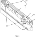
- an assembly portion 240 is disposed on the button pad 24, and referring to FIG. 3 , the button pad 24 is assembled with the second housing 202 through the assembly portion 240.
- the assembly portion 240 is disposed on the button pad 24, and the button pad 24 is assembled with the second housing 202 through the assembly portion 240.
- the fixed assembly of the entire functional module (including the functional module component 21, the functional module FPC 22, the button piece 23, and the button pad 24) inside the device is implemented by the assembly portion 240 on the button pad 24.
- an original side button support steel piece 104 is omitted to reduce costs, and the assembly is performed directly through the assembly portion 240, so that the assembly manner is simpler.
- an area of the button pad 24 needs to be increased, so that an adhesive area between the button pad 24 and the button piece 23 is larger, which is beneficial to improving the adhesive strength between the button pad 24 and the button piece 23.
- the assembly portion 240 includes two first assembly members 241 disposed at two ends of the button pad 24, respectively, and two second assembly members 242 are disposed on the second housing 202.
- the button pad 24 is usually in a shape of an elongated rectangle or an ellipse, so that the two first assembly members 241 may be disposed at two ends of the button pad 24 in a length direction, respectively; and each first assembly member 241 fits with one of the second assembly members 242.
- the second assembly member 242 is disposed on the second housing 202, and the assembly members fit with each other in pairs.
- the first assembly member 241 has a first connecting end 2411 and a first assembly end 2412
- the second assembly member 242 has a second connecting end 2421 and a second assembly end 2422
- the first assembly member 241 is fixedly connected to the button pad 24 through the first connecting end 2411
- the second assembly member 242 is fixedly connected to the second housing 202 through the second connecting end 2421
- the first assembly end 2412 of the first assembly member 241 is detachably coupled to the second assembly end 2422 of the second assembly member 242.
- the first assembly end 2412 of the first assembly member 241 bends in a first direction to form a concave portion; and the second assembly end 2422 of the second assembly member 242 extends in a second direction and abuts against the concave portion, that is, the concave portion formed by bending of the first assembly end 2412 can play a movement limiting role for the second assembly end 2422.
- the button FPC 25 when the button FPC 25 is pressed by the button pad 24, the button FPC 25 can be prevented from being overly pressed and the device can be prevented from being damaged.
- the second assembly end 2422 of the second assembly member 242 extends in the second direction and clamps to the concave portion, that is, the concave portion formed by bending of the first assembly end 2412 can play a locking role for the second assembly end 2422 to improve assembly stability.
- the first direction is perpendicular to the second direction, that is, the first assembly end 2412 and the second assembly end 2422 are cross-assembled opposite each other to enhance the assembly stability.
- the first direction is a direction in which the button FPC 25 is pressed, that is, the first assembly end 2412 is bent in a direction of the button FPC 25 to form the concave portion.
- a function of the first button is implemented by pressing the button FPC 25 through the button pad 24.
- the button pad 24 moves slightly toward the button FPC 25.
- the first assembly end 2412 and the second assembly end 2422 bent toward the button FPC 25 fit with each other to ensure that the entire functional module is firmly assembled and prevent the functional module from being misplaced or damaged due to the use of the first button.
- the first assembly end 2412 of the first assembly member 241 may be an annular structure, that is, the first assembly end 2412 may be a ring, and the second assembly end 2422 of the second assembly member 242 may be a columnar structure, that is, the first assembly end 2412 may be a column.
- the first assembly end 2412 of the first assembly member 241 is sleeved on the second assembly end 242 of the second assembly member 242.
- a fitting manner of the ring and the column is used.
- the assembly difficulty can be reduced to improve the assembly efficiency of the device.
- the fitting stability of the first assembly end 2412 and the second assembly end 2422 can be ensured to prevent the functional module from being misplaced or damaged.
- a laser engraving structure is disposed on a side surface of the button piece 23 close to the button pad 24, and it may be understood that the button pad 24 is omitted in FIG. 6 for clarity of display.
- an entire surface of the button piece 23 is laser engraved, to increase a dyne value of the surface of the button piece 23 (that is, a surface tension coefficient, which is commonly referred to as the dyne value), thereby increasing the bonding strength after the button piece 23 is bonded to the button pad 24.
- a dyne value of the surface of the button piece 23 that is, a surface tension coefficient, which is commonly referred to as the dyne value
- oblique section lines in FIG. 6 are only used to identify the laser engraving on the button piece 23, and do not represent that an actual laser engraved shape is a shape shown in FIG. 6 .
- the laser engraved shape on the surface of the button piece 23 is not specifically limited in the embodiments of this application.
- the button pad 24 is bonded on the button piece 23, where a first bonding region 231 and two second boning regions 232 are provided between the button pad 24 and the button piece 23, the two second boning regions 232 are located on two sides of the first bonding region 231, and the button pad 24 is bonded in the first bonding region 231 and the second bonding region 232 in different manners.
- a middle bonding thickness size of the button pad 24 needs to be more precise. Therefore, two types of bonding regions are obtained through division between the button pad 24 and the button piece 23, a middle part is the first bonding region 231, and two end parts are the second bonding regions 232, that is, the regions obtained through division by the oblique section lines in FIG. 7 .
- the first bonding region 231 is used to ensure the precise bonding thickness size, and the second bonding regions 232 are used to ensure the bonding strength.
- the button pad 24 is bonded to the button piece 23 in the first bonding region 231 through a double-sided adhesive tape, and the button pad 24 is bonded to the button piece 24 in the second bonding regions 232 in a dispensing manner.
- the first bonding region 231 in the middle part adopts a manner of sticking a double-sided adhesive tape, which can ensure that the thickness size of the entire functional module is more precise after the button pad 24 is bonded, and the second bonding regions 232 in the two end parts adopt a dispensing manner, which can improve the bonding strength of the button pad 24, so that the bonding is more reliable.
- the electronic device further includes a reinforcement piece 27.
- the reinforcement piece 27 is disposed on a side of the button FPC 25 away from the button pad 24, and the reinforcement piece 27 is fixed on the first housing 201.
- the reinforcement piece 27 may also be referred to as an FPC reinforcement piece, and the button FPC 25 is fixed on the first housing 201 through the reinforcement piece 27.
- the reinforcement piece 27 in the embodiments of this application is not equivalent to the side button support steel piece 104 in FIG. 1c .
- the reinforcement piece 27 in the embodiments of this application is only used to fix the button FPC 25 and complement the structural strength, while the side button support steel piece 104 in FIG. 1c is also used to fix the entire functional module. Since a strength requirement on the reinforcement piece 27 is lower than that on the side button support steel piece 104, in an actual application scenario, a thickness of the reinforcement piece 27 may be at least 0.15 mm thinner than that of the side button support steel piece 104.
- the reinforcement piece 27 is bonded to the first housing 201 through a double-sided adhesive tape.
- a thickness of the double-sided adhesive tape between the reinforcement piece 27 and the first housing 201 ranges from 0.04 mm to 0.06 mm, and is preferably 0.05 mm.
- the reinforcement piece 27 is fixed by using the double-sided adhesive tape, which is convenient for controlling the bonding thickness size.
- a gap of 0.2 mm is required between the side button support steel piece 104 and the main upper housing 101 (that is, the bonding thickness in the existing solution).
- the thickness of the double-sided adhesive tape between the reinforcement piece 27 and the first housing 201 can be only 0.05 mm. In this way, a space of 0.15 mm is saved for the first housing 201, so that a side wall of the first housing 201 may be thickened by more than 0.3 mm.
- the electronic device in the embodiments of this application further includes a second button, and a button FPC is electrically connected to the second button.
- the button FPC is applied to both the first button and the second button, that is, FPCs of the first button and the second button are made into one, which can reduce the cost of the FPCs.
- the first button may be a power button
- the second button may be a volume button.
Landscapes
- Engineering & Computer Science (AREA)
- Theoretical Computer Science (AREA)
- Computer Hardware Design (AREA)
- Computer Security & Cryptography (AREA)
- Physics & Mathematics (AREA)
- General Engineering & Computer Science (AREA)
- General Physics & Mathematics (AREA)
- Software Systems (AREA)
- Human Computer Interaction (AREA)
- Signal Processing (AREA)
- Microelectronics & Electronic Packaging (AREA)
- Casings For Electric Apparatus (AREA)
- Mounting Components In General For Electric Apparatus (AREA)
- Push-Button Switches (AREA)
Abstract
Description
- This application claims the priority of
Chinese Patent Application No. 202011238134.9 filed in China on November 9, 2020 - Embodiments of this application relate to the field of communication technologies, and in particular, to an electronic device.
- An assembly manner of a lateral fingerprint module in the related art is to assemble a fingerprint module on a lower housing of an electronic device, and use a plastic or stainless steel support to fix the fingerprint module. In this assembly manner, the entire fingerprint module occupies a large space of the electronic device, and more glue is reduced for an upper housing of the electronic device to avoid empty space, which greatly affects the strength of the entire device.
- An objective of embodiments of this application is to provide an electronic device, which can resolve the problem that a fingerprint module occupies a large space of the electronic device.
- To resolve the foregoing technical problem, this application is implemented as follows.
- The embodiments of this application provide an electronic device, including a first housing, a second housing, and a first button, where
- the first housing and the second housing form an accommodating space for accommodating the first button, and
- the first button includes a functional module component, a functional module FPC, a button piece, a button pad, and a button FPC;
- in the accommodating space, the button FPC, the button pad, the button piece, and the functional module component are sequentially arranged from inside to outside;
- the functional module component is electrically connected to the functional module FPC;
- the functional module component and the button pad are fixed on the button piece; and
- an assembly portion is disposed on the button pad, and the button pad is assembled with the second housing through the assembly portion.
- In the embodiments of this application, the button pad of the first button is assembled on the second housing through the assembly portion, to implement fixed assembly of the entire functional module in the electronic device housing. An original plastic or stainless steel support is omitted, which saves the space of the electronic device, and the saved size can be used to add glue to the electronic device housing, thereby improving the strength of the entire device.
-
-
FIG. 1a is a schematic structural diagram of a fingerprint module in an existing electronic device; -
FIG. 1b is a schematic structural diagram 1 of an existing electronic device; -
FIG. 1c is a schematic structural diagram 2 of an existing electronic device; -
FIG. 2 is a schematic structural diagram 1 of a functional module in an electronic device according to an embodiment of this application; -
FIG. 3 is a schematic structural diagram 1 of an electronic device according to an embodiment of this application; -
FIG. 4 is a schematic enlarged diagram of region A inFIG. 3 ; -
FIG. 5 is a schematic structural diagram 2 of an electronic device according to an embodiment of this application; -
FIG. 6 is a schematic structural diagram 2 of a functional module in an electronic device according to an embodiment of this application; and -
FIG. 7 is a schematic structural diagram 3 of a functional module in an electronic device according to an embodiment of this application. - The following clearly and completely describes the technical solutions in the embodiments of this application with reference to the accompanying drawings in the embodiments of this application. Apparently, the described embodiments are some of the embodiments of this application rather than all of the embodiments. All other embodiments obtained by a person of ordinary skill in the art based on the embodiments of this application without creative efforts shall fall within the protection scope of this application.
- The specification and claims of this application, and terms "first" and "second" are used to distinguish similar objects, but are unnecessarily used to describe a specific sequence or order. It should be understood that the data in such a way are interchangeable in proper circumstances, so that the embodiments of this application can be implemented in other orders than the order illustrated or described herein. Objects distinguished by "first", "second", and the like are usually one type, and the number of objects is not limited. For example, the first object may be one or more than one. In addition, in the specification and the claims, "and/or" represents at least one of the connected objects, and the character "/" generally represents an "or" relationship between the associated objects.
- To better understand the solution provided in the embodiments of this application, the following content is described first:
FIG. 1a shows a conventional fingerprint module structure, including a buttonsoft rubber pad 11, abutton steel piece 12, afingerprint module component 13, and a fingerprint module FPC (Flexible Printed Circuit, FPC for short) 14. In an existing electronic device, a fingerprint module is usually integrated with a power button, which is convenient for a user to perform fingerprint verification while pressing the power button, thereby implementing one-step operation to complete identity verification and turn the device screen on. In an existing assembly manner, the buttonsoft rubber pad 11 is bonded on thebutton steel piece 12 through dispensing, and when the user presses the power button, the buttonsoft rubber pad 11 presses a power button FPC and implements a power button function. - Specifically, referring to
FIG. 1b , thefingerprint module component 13 is assembled on a main lower housing 102 (which may also be a lower housing, a back housing, or the like, which is not specifically limited in this application) of the electronic device. The power button FPC 103 is first integrated with a side buttonsupport steel piece 104 and then assembled on the mainlower housing 102, and the fingerprint module is fixed to implement the power button function. - Further,
FIG. 1c shows an assembled state of the fingerprint module in the entire device, and there are disadvantages as follows. - (1) The
fingerprint module component 13 is fixed by the side buttonsupport steel piece 104, and a cost of the side buttonsupport steel piece 104 increases a cost of the entire device. - (2) Because the side button
support steel piece 104 is required to assemble the power button FPC 103 and fix thefingerprint module component 13, a steel piece needs a larger thickness, usually more than 0.3 mm, and correspondingly, more glue is reduced for the mainlower housing 101 of the electronic device, which greatly affects the strength of the mainupper housing 101 and the entire device. - (3) The button
soft rubber pad 11 is small in area, and is bonded to thebutton steel piece 12 through dispensing, so that the bonding strength is insufficient and it is prone to loosening. - (4) The button
soft rubber pad 11 is bonded by glue, the consistency of glue thickness is not easy to control, and a thickness size of the entire fingerprint module cannot meet a standard requirement of 0.05 thickness tolerance, which greatly affects hand feeling of the button. If a double-sided adhesive tape is used for bonding, a thicker double-sided adhesive tape is required to achieve the viscosity of the existing glue, and the thicker double-sided adhesive tape increases a component size and occupies more internal space of the device. - An electronic device provided in the embodiments of this application is described below through specific embodiments and application scenarios thereof with reference to the accompanying drawings.
- It should be noted that, the electronic device in the embodiments of this application may be a mobile phone, a tablet computer, a notebook computer, an intelligent furniture, an ultra-mobile personal computer (Ultra-Mobile Personal Computer, UMPC), a netbook, a personal digital assistant (Personal Digital Assistant, PDA), or the like. The type of the electronic device is not specifically limited in the embodiments of this application.
- Referring to
FIG. 2 to FIG. 5 , the embodiments of this application provide an electronic device, including afirst housing 201, asecond housing 202, and afirst button 203. Thefirst button 203 may be a functional button such as a power button or a volume control button, which is not specifically limited in the embodiments of this application. - As shown in
FIG. 5 , thefirst housing 201 and thesecond housing 202 form an accommodating space for accommodating thefirst button 203. - The
first housing 201 may also be referred to as an upper housing, a main upper housing, a front housing, or the like. Thesecond housing 202 may also be referred to as a lower housing, a main lower housing, a back housing, or the like. The names of thefirst housing 201 and thesecond housing 202 are not specifically limited in the embodiments of this application. - The
first button 203 includes afunctional module component 21, afunctional module FPC 22, abutton piece 23, abutton pad 24, and abutton FPC 25. Optionally, thefunctional module component 21 is a fingerprint module component, and thefunctional module FPC 22 is a fingerprint module FPC. - It may be understood that, as shown in
FIG. 5 , the electronic device further includes amiddle frame 26. It should be noted that, themiddle frame 26 is higher than an entire functional module as a whole. However, a position corresponding to the functional module may be set to be slightly lower than the functional module (for example, a concave structure is made). In this way, on one hand, the functional module may be exposed, which is convenient for the functional module to function. For example, if the functional module is a fingerprint module, a concave structure is provided at a position corresponding to the fingerprint module in themiddle frame 26, which is convenient for fingerprint recognition. On the other hand, the concave design is also convenient for the user to directly find the position of the functional module when using the electronic device, which is convenient for operation. - It should be noted that, in the embodiments of this application, there may be a plurality of types of functional modules. For example, a fingerprint module for fingerprint recognition, a vibration module for a key button feedback, a pressure detection module for button force detection of the user, or the like. The type of the functional module is not specifically limited in the embodiments of this application. The
functional module component 21 may be a chip corresponding to a function, for example, a fingerprint chip, or may be a sensor corresponding to a function, for example, a pressure sensor. The specific type of thefunctional module component 21 is not limited in the embodiments of this application. Thefunctional module FPC 22 is configured to transmit a signal or information received by thefunctional module component 21. - As shown in
FIG. 5 , in the accommodating space, thebutton FPC 25, thebutton pad 24, thebutton piece 23, and thefunctional module component 21 are sequentially arranged from inside to outside. - As shown in
FIG. 2 andFIG. 3 , thefunctional module component 21 is electrically connected to thefunctional module FPC 22. Further, thefunctional module FPC 22 may further be electrically connected to a processor in the electronic device, and is configured to transmit a signal received by thefunctional module component 21 or a control signal sent by the processor. - As shown in
FIG. 2 , thefunctional module component 21 and thebutton pad 24 are fixed on two opposite side surfaces of thebutton piece 23, where thebutton pad 24 may be fixed to thebutton piece 23 through gluing. - The
button pad 24 may also be referred to as a button soft rubber pad, and thebutton piece 23 may also be referred to as a button steel piece. As shown inFIG. 5 , thebutton FPC 25 is located on a side of thebutton pad 24 away from thebutton piece 23. In this way, when the user presses thefirst button 203, thebutton FPC 25 is pressed by thebutton pad 24 to implement a button function. For example, when thefirst button 203 is a power button, thebutton FPC 25 is pressed by thebutton pad 24 to control the device screen on or off. Specifically, thebutton pad 24 may be a switch element or a contact on thebutton FPC 25, which is not specifically limited in the embodiments of this application. - The
button piece 23 is mainly configured to carry thefunctional module component 21 and thebutton pad 24, and a metal material such as hard plastic or steel may be used to ensure the structural strength. Thebutton pad 24 may be made of a material with a certain elastic buffering effect such as rubber, or silica gel, which can protect thebutton FPC 25, and provide a certain pressing feedback for the user to improve user experience. The materials of thebutton pad 24 and thebutton piece 23 are not specifically limited in the embodiments of this application. - Referring to
FIG. 2 , anassembly portion 240 is disposed on thebutton pad 24, and referring toFIG. 3 , thebutton pad 24 is assembled with thesecond housing 202 through theassembly portion 240. - In the embodiments of this application, the
assembly portion 240 is disposed on thebutton pad 24, and thebutton pad 24 is assembled with thesecond housing 202 through theassembly portion 240. In this way, the fixed assembly of the entire functional module (including thefunctional module component 21, thefunctional module FPC 22, thebutton piece 23, and the button pad 24) inside the device is implemented by theassembly portion 240 on thebutton pad 24. Compared with the existing electronic device shown inFIG. 1a to FIG. 1c , an original side buttonsupport steel piece 104 is omitted to reduce costs, and the assembly is performed directly through theassembly portion 240, so that the assembly manner is simpler. After the side buttonsupport steel piece 104 is omitted, an internal space of the device required for assembling the functional module is reduced, and the saved space can be used to thicken a side edge of thefirst housing 201, to improve the strength and reliability of thefirst housing 201 and the entire device. - In addition, because the
assembly portion 240 needs to be arranged on thebutton pad 24, in actual implementation, an area of thebutton pad 24 needs to be increased, so that an adhesive area between thebutton pad 24 and thebutton piece 23 is larger, which is beneficial to improving the adhesive strength between thebutton pad 24 and thebutton piece 23. - Still referring to
FIG. 3 , in some implementations, theassembly portion 240 includes twofirst assembly members 241 disposed at two ends of thebutton pad 24, respectively, and twosecond assembly members 242 are disposed on thesecond housing 202. - In an actual application scenario, the
button pad 24 is usually in a shape of an elongated rectangle or an ellipse, so that the twofirst assembly members 241 may be disposed at two ends of thebutton pad 24 in a length direction, respectively; and eachfirst assembly member 241 fits with one of thesecond assembly members 242. - In the embodiments of this application, to fit with the
first assembly member 241 on thebutton pad 24, thesecond assembly member 242 is disposed on thesecond housing 202, and the assembly members fit with each other in pairs. - Referring to
FIG. 4 , in some implementations, thefirst assembly member 241 has a first connectingend 2411 and afirst assembly end 2412, and thesecond assembly member 242 has a second connectingend 2421 and asecond assembly end 2422; thefirst assembly member 241 is fixedly connected to thebutton pad 24 through the first connectingend 2411, and thesecond assembly member 242 is fixedly connected to thesecond housing 202 through the second connectingend 2421; and thefirst assembly end 2412 of thefirst assembly member 241 is detachably coupled to thesecond assembly end 2422 of thesecond assembly member 242. - Still referring to
FIG. 4 , in some implementations, thefirst assembly end 2412 of thefirst assembly member 241 bends in a first direction to form a concave portion; and thesecond assembly end 2422 of thesecond assembly member 242 extends in a second direction and abuts against the concave portion, that is, the concave portion formed by bending of thefirst assembly end 2412 can play a movement limiting role for thesecond assembly end 2422. In this way, when thebutton FPC 25 is pressed by thebutton pad 24, thebutton FPC 25 can be prevented from being overly pressed and the device can be prevented from being damaged. - Alternatively, the
second assembly end 2422 of thesecond assembly member 242 extends in the second direction and clamps to the concave portion, that is, the concave portion formed by bending of thefirst assembly end 2412 can play a locking role for thesecond assembly end 2422 to improve assembly stability. - The first direction is perpendicular to the second direction, that is, the
first assembly end 2412 and thesecond assembly end 2422 are cross-assembled opposite each other to enhance the assembly stability. - Further, the first direction is a direction in which the
button FPC 25 is pressed, that is, thefirst assembly end 2412 is bent in a direction of thebutton FPC 25 to form the concave portion. The reason is that a function of the first button is implemented by pressing thebutton FPC 25 through thebutton pad 24. During use of the first button, thebutton pad 24 moves slightly toward thebutton FPC 25. In this case, thefirst assembly end 2412 and thesecond assembly end 2422 bent toward thebutton FPC 25 fit with each other to ensure that the entire functional module is firmly assembled and prevent the functional module from being misplaced or damaged due to the use of the first button. - In some implementations, the
first assembly end 2412 of thefirst assembly member 241 may be an annular structure, that is, thefirst assembly end 2412 may be a ring, and thesecond assembly end 2422 of thesecond assembly member 242 may be a columnar structure, that is, thefirst assembly end 2412 may be a column. Thefirst assembly end 2412 of thefirst assembly member 241 is sleeved on thesecond assembly end 242 of thesecond assembly member 242. - In the embodiments of this application, a fitting manner of the ring and the column is used. On one hand, the assembly difficulty can be reduced to improve the assembly efficiency of the device. On the other hand, the fitting stability of the
first assembly end 2412 and thesecond assembly end 2422 can be ensured to prevent the functional module from being misplaced or damaged. - Referring to
FIG. 6 , in some implementations, a laser engraving structure is disposed on a side surface of thebutton piece 23 close to thebutton pad 24, and it may be understood that thebutton pad 24 is omitted inFIG. 6 for clarity of display. - In the embodiments of this application, an entire surface of the
button piece 23 is laser engraved, to increase a dyne value of the surface of the button piece 23 (that is, a surface tension coefficient, which is commonly referred to as the dyne value), thereby increasing the bonding strength after thebutton piece 23 is bonded to thebutton pad 24. - It should be noted that, oblique section lines in
FIG. 6 are only used to identify the laser engraving on thebutton piece 23, and do not represent that an actual laser engraved shape is a shape shown inFIG. 6 . The laser engraved shape on the surface of thebutton piece 23 is not specifically limited in the embodiments of this application. - Referring to
FIG. 7 , in some implementations, thebutton pad 24 is bonded on thebutton piece 23, where afirst bonding region 231 and twosecond boning regions 232 are provided between thebutton pad 24 and thebutton piece 23, the twosecond boning regions 232 are located on two sides of thefirst bonding region 231, and thebutton pad 24 is bonded in thefirst bonding region 231 and thesecond bonding region 232 in different manners. - In the embodiments of this application, considering that the
button FPC 25 is pressed by the middle of thebutton pad 24, a middle bonding thickness size of thebutton pad 24 needs to be more precise. Therefore, two types of bonding regions are obtained through division between thebutton pad 24 and thebutton piece 23, a middle part is thefirst bonding region 231, and two end parts are thesecond bonding regions 232, that is, the regions obtained through division by the oblique section lines inFIG. 7 . Thefirst bonding region 231 is used to ensure the precise bonding thickness size, and thesecond bonding regions 232 are used to ensure the bonding strength. - Specifically, the
button pad 24 is bonded to thebutton piece 23 in thefirst bonding region 231 through a double-sided adhesive tape, and thebutton pad 24 is bonded to thebutton piece 24 in thesecond bonding regions 232 in a dispensing manner. - In the embodiments of this application, the
first bonding region 231 in the middle part adopts a manner of sticking a double-sided adhesive tape, which can ensure that the thickness size of the entire functional module is more precise after thebutton pad 24 is bonded, and thesecond bonding regions 232 in the two end parts adopt a dispensing manner, which can improve the bonding strength of thebutton pad 24, so that the bonding is more reliable. - Still referring to
FIG. 5 , the electronic device further includes areinforcement piece 27. Thereinforcement piece 27 is disposed on a side of thebutton FPC 25 away from thebutton pad 24, and thereinforcement piece 27 is fixed on thefirst housing 201. - In the embodiments of this application, the
reinforcement piece 27 may also be referred to as an FPC reinforcement piece, and thebutton FPC 25 is fixed on thefirst housing 201 through thereinforcement piece 27. - It should be noted that, the
reinforcement piece 27 in the embodiments of this application is not equivalent to the side buttonsupport steel piece 104 inFIG. 1c . Thereinforcement piece 27 in the embodiments of this application is only used to fix thebutton FPC 25 and complement the structural strength, while the side buttonsupport steel piece 104 inFIG. 1c is also used to fix the entire functional module. Since a strength requirement on thereinforcement piece 27 is lower than that on the side buttonsupport steel piece 104, in an actual application scenario, a thickness of thereinforcement piece 27 may be at least 0.15 mm thinner than that of the side buttonsupport steel piece 104. - Further, the
reinforcement piece 27 is bonded to thefirst housing 201 through a double-sided adhesive tape. - Further, a thickness of the double-sided adhesive tape between the
reinforcement piece 27 and thefirst housing 201 ranges from 0.04 mm to 0.06 mm, and is preferably 0.05 mm. - In the embodiments of this application, the
reinforcement piece 27 is fixed by using the double-sided adhesive tape, which is convenient for controlling the bonding thickness size. In the existing electronic device shown inFIG. 1a to FIG. 1c , a gap of 0.2 mm is required between the side buttonsupport steel piece 104 and the main upper housing 101 (that is, the bonding thickness in the existing solution). By comparison, in the solution in the embodiments of this application, the thickness of the double-sided adhesive tape between thereinforcement piece 27 and thefirst housing 201 can be only 0.05 mm. In this way, a space of 0.15 mm is saved for thefirst housing 201, so that a side wall of thefirst housing 201 may be thickened by more than 0.3 mm. - In some implementations, the electronic device in the embodiments of this application further includes a second button, and a button FPC is electrically connected to the second button.
- In the embodiments of this application, the button FPC is applied to both the first button and the second button, that is, FPCs of the first button and the second button are made into one, which can reduce the cost of the FPCs. Specifically, the first button may be a power button, and the second button may be a volume button.
- It should be noted that the terms "include", "comprise", or any other variation thereof in this specification is intended to cover a non-exclusive inclusion, which specifies the presence of stated processes, methods, objects, or apparatuses, but does not preclude the presence or addition of one or more other processes, methods, objects, or apparatuses. Without more limitations, elements defined by the sentence "including one" does not exclude that there are still other same elements in the processes, methods, objects, or apparatuses. In addition, it should be noted that, the scope of the method and apparatus in the embodiments of this application is not limited to performing functions in the order shown or discussed, and it may further include performing the functions in a substantially simultaneous manner or in reverse order according to the functions involved. For example, the described method may be performed in a different order than described, and various steps may also be added, omitted, or combined. In addition, features described with reference to some examples may be combined in other examples.
- The embodiments of this application are described above with reference to the accompanying drawings, but this application is not limited to the foregoing specific embodiments, which are merely illustrative rather than limited. Under the inspiration of this application, a person of ordinary skill in the art may make various variations without departing from the scope of this application and the protection of the claims, and such variations shall fall within the protection of this application.
Claims (10)
- An electronic device, comprising a first housing, a second housing, and a first button, whereinthe first housing and the second housing form an accommodating space for accommodating the first button, andthe first button comprises a functional module component, a functional module FPC, a button piece, a button pad, and a button FPC;in the accommodating space, the button FPC, the button pad, the button piece, and the functional module component are sequentially arranged from inside to outside;the functional module component is electrically connected to the functional module FPC;the functional module component and the button pad are fixed on the button piece; andan assembly portion is disposed on the button pad, and the button pad is assembled with the second housing through the assembly portion.
- The electronic device according to claim 1, wherein the assembly portion comprises two first assembly members disposed at two ends of the button pad, respectively, and two second assembly members are disposed on the second housing; and
each first assembly member fits with one of the second assembly members. - The electronic device according to claim, whereinthe first assembly member has a first connecting end and a first assembly end, and the second assembly member has a second connecting end and a second assembly end;the first assembly member is fixedly connected to the button pad through the first connecting end, and the second assembly member is fixedly connected to the second housing through the second connecting end; andthe first assembly end of the first assembly member is detachably connected to the second assembly end of the second assembly member.
- The electronic device according to claim 3, whereinthe first assembly end of the first assembly member bends in a first direction to form a concave portion; andthe second assembly end of the second assembly member extends in a second direction, and abuts against or clamps to the concave portion, whereinthe first direction is perpendicular to the second direction.
- The electronic device according to claim 4, wherein the first direction is a direction toward the button FPC.
- The electronic device according to claim 3, whereinthe first assembly end of the first assembly member is an annular structure, and the second assembly end of the second assembly member is a columnar structure; andthe first assembly end of the first assembly member is sleeved on the second assembly end of the second assembly member.
- The electronic device according to claim 1, wherein a laser engraving structure is disposed on a side surface of the button piece close to the button pad.
- The electronic device according to claim 7, wherein the button pad is bonded on the button piece;
a first bonding region and second bonding regions are provided between the button pad and the button piece, the second bonding regions are located on two sides of the first bonding region, and the button pad is bonded in the first bonding region and the second bonding regions in different manners. - The electronic device according to claim 8, wherein the button pad is bonded to the button piece in the first bonding region through a double-sided adhesive tape, and the button pad is bonded to the button piece in the second bonding regions in a dispensing manner.
- The electronic device according to claim 1, further comprising a reinforcement piece, wherein
the reinforcement piece is disposed on a side of the button FPC away from the button pad, and the reinforcement piece is fixed on the first housing.
Applications Claiming Priority (2)
| Application Number | Priority Date | Filing Date | Title |
|---|---|---|---|
| CN202011238134.9A CN112216545A (en) | 2020-11-09 | 2020-11-09 | Electronic device |
| PCT/CN2021/128388 WO2022095889A1 (en) | 2020-11-09 | 2021-11-03 | Electronic device |
Publications (2)
| Publication Number | Publication Date |
|---|---|
| EP4243045A1 true EP4243045A1 (en) | 2023-09-13 |
| EP4243045A4 EP4243045A4 (en) | 2024-04-03 |
Family
ID=74058420
Family Applications (1)
| Application Number | Title | Priority Date | Filing Date |
|---|---|---|---|
| EP21888586.1A Pending EP4243045A4 (en) | 2020-11-09 | 2021-11-03 | Electronic device |
Country Status (5)
| Country | Link |
|---|---|
| US (1) | US12461571B2 (en) |
| EP (1) | EP4243045A4 (en) |
| JP (1) | JP7559237B2 (en) |
| CN (1) | CN112216545A (en) |
| WO (1) | WO2022095889A1 (en) |
Families Citing this family (2)
| Publication number | Priority date | Publication date | Assignee | Title |
|---|---|---|---|---|
| CN112216545A (en) | 2020-11-09 | 2021-01-12 | 维沃移动通信有限公司 | Electronic device |
| CN113972082B (en) | 2021-09-06 | 2022-08-12 | 荣耀终端有限公司 | Buttons and Electronic Equipment |
Family Cites Families (14)
| Publication number | Priority date | Publication date | Assignee | Title |
|---|---|---|---|---|
| CN101859659B (en) * | 2009-04-13 | 2012-12-19 | 深圳富泰宏精密工业有限公司 | Side key and electronic device applying same |
| CN103076843A (en) * | 2011-10-26 | 2013-05-01 | 富泰华工业(深圳)有限公司 | Bonding structure and electronic device using same |
| JP2014186847A (en) * | 2013-03-22 | 2014-10-02 | Fujitsu Ltd | Electronic apparatus |
| KR20150099295A (en) * | 2014-02-21 | 2015-08-31 | 삼성전자주식회사 | Electronic device including a physical key |
| KR102528424B1 (en) * | 2016-08-31 | 2023-05-04 | 삼성전자주식회사 | Electric component and electronic device with the same |
| CN206789459U (en) * | 2017-04-28 | 2017-12-22 | 维沃移动通信有限公司 | A kind of button assembling assembly and electronic equipment |
| CN108124031B (en) * | 2017-12-21 | 2020-08-18 | 上海摩软通讯技术有限公司 | Side key, mobile terminal comprising side key and configuration system and method thereof |
| CN110188740B (en) * | 2019-07-02 | 2025-05-06 | 闻泰通讯股份有限公司 | Fingerprint recognition module installation structure and electronic equipment |
| CN110807446A (en) * | 2019-12-16 | 2020-02-18 | 昆山丘钛微电子科技有限公司 | Fingerprint module mounting structure and electronic equipment |
| CN210694032U (en) * | 2020-02-28 | 2020-06-05 | Oppo广东移动通信有限公司 | an electronic device |
| CN111478996B (en) * | 2020-04-29 | 2021-06-01 | Oppo广东移动通信有限公司 | Electronic equipment |
| CN111638762A (en) * | 2020-06-30 | 2020-09-08 | 西安易朴通讯技术有限公司 | Bracket assembly, fingerprint module, electronic device and installation method |
| CN112216545A (en) * | 2020-11-09 | 2021-01-12 | 维沃移动通信有限公司 | Electronic device |
| CN214477088U (en) * | 2021-03-23 | 2021-10-22 | 维沃移动通信有限公司 | Key assembly and electronic equipment |
-
2020
- 2020-11-09 CN CN202011238134.9A patent/CN112216545A/en active Pending
-
2021
- 2021-11-03 EP EP21888586.1A patent/EP4243045A4/en active Pending
- 2021-11-03 WO PCT/CN2021/128388 patent/WO2022095889A1/en not_active Ceased
- 2021-11-03 JP JP2023527739A patent/JP7559237B2/en active Active
-
2023
- 2023-05-07 US US18/313,346 patent/US12461571B2/en active Active
Also Published As
| Publication number | Publication date |
|---|---|
| US12461571B2 (en) | 2025-11-04 |
| EP4243045A4 (en) | 2024-04-03 |
| JP2023548618A (en) | 2023-11-17 |
| US20230273651A1 (en) | 2023-08-31 |
| CN112216545A (en) | 2021-01-12 |
| JP7559237B2 (en) | 2024-10-01 |
| WO2022095889A1 (en) | 2022-05-12 |
Similar Documents
| Publication | Publication Date | Title |
|---|---|---|
| EP1507273B1 (en) | Keypad assembly | |
| US12461571B2 (en) | Electronic device | |
| US6777626B2 (en) | Input device and portable equipment using the same | |
| CN110188740B (en) | Fingerprint recognition module installation structure and electronic equipment | |
| US20220101761A1 (en) | Display assembly and display apparatus | |
| KR101208218B1 (en) | Button switch assembly of mobile terminal | |
| CN210075346U (en) | an electronic device | |
| CN206212063U (en) | Electronic equipment | |
| CN106385473A (en) | Shell, fingerprint module and mobile terminal | |
| CN210491417U (en) | an electronic device | |
| CN210015452U (en) | Mounting structure and electronic equipment of fingerprint identification module | |
| CN212906326U (en) | Electronic device | |
| CN211184486U (en) | Electronic equipment | |
| CN210899267U (en) | Fingerprint identification key and electronic device | |
| US6504595B2 (en) | LCD connection | |
| CN206353802U (en) | Housing, fingerprint module and mobile terminal | |
| CN112671954B (en) | an electronic device | |
| US20090065335A1 (en) | Multi-functional keypad module for a mobile phone | |
| CN209785800U (en) | Button structure capable of reducing compression feeling of elastic sheet and electronic equipment | |
| CN105283009A (en) | Shell assembly and terminal equipment | |
| US12439511B2 (en) | Input device | |
| CN221993879U (en) | Touchpads and electronic devices | |
| CN117148989B (en) | Pressure-sensing touch component and electronic equipment | |
| CN213880209U (en) | a headphone | |
| KR100950142B1 (en) | Keypad device of portable terminal |
Legal Events
| Date | Code | Title | Description |
|---|---|---|---|
| STAA | Information on the status of an ep patent application or granted ep patent |
Free format text: STATUS: THE INTERNATIONAL PUBLICATION HAS BEEN MADE |
|
| PUAI | Public reference made under article 153(3) epc to a published international application that has entered the european phase |
Free format text: ORIGINAL CODE: 0009012 |
|
| STAA | Information on the status of an ep patent application or granted ep patent |
Free format text: STATUS: REQUEST FOR EXAMINATION WAS MADE |
|
| 17P | Request for examination filed |
Effective date: 20230606 |
|
| AK | Designated contracting states |
Kind code of ref document: A1 Designated state(s): AL AT BE BG CH CY CZ DE DK EE ES FI FR GB GR HR HU IE IS IT LI LT LU LV MC MK MT NL NO PL PT RO RS SE SI SK SM TR |
|
| DAV | Request for validation of the european patent (deleted) | ||
| DAX | Request for extension of the european patent (deleted) | ||
| A4 | Supplementary search report drawn up and despatched |
Effective date: 20240306 |
|
| RIC1 | Information provided on ipc code assigned before grant |
Ipc: H04M 1/02 20060101ALI20240229BHEP Ipc: G06F 21/32 20130101ALI20240229BHEP Ipc: G06F 1/16 20060101ALI20240229BHEP Ipc: H04M 1/23 20060101ALI20240229BHEP Ipc: H05K 5/02 20060101ALI20240229BHEP Ipc: H01H 13/14 20060101ALI20240229BHEP Ipc: H01H 13/78 20060101AFI20240229BHEP |
|
| GRAP | Despatch of communication of intention to grant a patent |
Free format text: ORIGINAL CODE: EPIDOSNIGR1 |
|
| STAA | Information on the status of an ep patent application or granted ep patent |
Free format text: STATUS: GRANT OF PATENT IS INTENDED |