EP4242617A1 - Pipeline pressure monitoring device - Google Patents
Pipeline pressure monitoring device Download PDFInfo
- Publication number
- EP4242617A1 EP4242617A1 EP20962327.1A EP20962327A EP4242617A1 EP 4242617 A1 EP4242617 A1 EP 4242617A1 EP 20962327 A EP20962327 A EP 20962327A EP 4242617 A1 EP4242617 A1 EP 4242617A1
- Authority
- EP
- European Patent Office
- Prior art keywords
- vent nozzle
- housing
- sliding sleeve
- circuit board
- vent
- Prior art date
- Legal status (The legal status is an assumption and is not a legal conclusion. Google has not performed a legal analysis and makes no representation as to the accuracy of the status listed.)
- Granted
Links
Images

Classifications
-
- G—PHYSICS
- G01—MEASURING; TESTING
- G01L—MEASURING FORCE, STRESS, TORQUE, WORK, MECHANICAL POWER, MECHANICAL EFFICIENCY, OR FLUID PRESSURE
- G01L19/00—Details of, or accessories for, apparatus for measuring steady or quasi-steady pressure of a fluent medium insofar as such details or accessories are not special to particular types of pressure gauges
- G01L19/0007—Fluidic connecting means
- G01L19/003—Fluidic connecting means using a detachable interface or adapter between the process medium and the pressure gauge
-
- G—PHYSICS
- G01—MEASURING; TESTING
- G01L—MEASURING FORCE, STRESS, TORQUE, WORK, MECHANICAL POWER, MECHANICAL EFFICIENCY, OR FLUID PRESSURE
- G01L19/00—Details of, or accessories for, apparatus for measuring steady or quasi-steady pressure of a fluent medium insofar as such details or accessories are not special to particular types of pressure gauges
- G01L19/0007—Fluidic connecting means
- G01L19/0038—Fluidic connecting means being part of the housing
-
- A—HUMAN NECESSITIES
- A61—MEDICAL OR VETERINARY SCIENCE; HYGIENE
- A61M—DEVICES FOR INTRODUCING MEDIA INTO, OR ONTO, THE BODY; DEVICES FOR TRANSDUCING BODY MEDIA OR FOR TAKING MEDIA FROM THE BODY; DEVICES FOR PRODUCING OR ENDING SLEEP OR STUPOR
- A61M5/00—Devices for bringing media into the body in a subcutaneous, intra-vascular or intramuscular way; Accessories therefor, e.g. filling or cleaning devices, arm-rests
- A61M5/14—Infusion devices, e.g. infusing by gravity; Blood infusion; Accessories therefor
- A61M5/168—Means for controlling media flow to the body or for metering media to the body, e.g. drip meters, counters ; Monitoring media flow to the body
- A61M5/16831—Monitoring, detecting, signalling or eliminating infusion flow anomalies
- A61M5/16854—Monitoring, detecting, signalling or eliminating infusion flow anomalies by monitoring line pressure
-
- G—PHYSICS
- G01—MEASURING; TESTING
- G01B—MEASURING LENGTH, THICKNESS OR SIMILAR LINEAR DIMENSIONS; MEASURING ANGLES; MEASURING AREAS; MEASURING IRREGULARITIES OF SURFACES OR CONTOURS
- G01B7/00—Measuring arrangements characterised by the use of electric or magnetic techniques
- G01B7/003—Measuring arrangements characterised by the use of electric or magnetic techniques for measuring position, not involving coordinate determination
-
- G—PHYSICS
- G01—MEASURING; TESTING
- G01L—MEASURING FORCE, STRESS, TORQUE, WORK, MECHANICAL POWER, MECHANICAL EFFICIENCY, OR FLUID PRESSURE
- G01L11/00—Measuring steady or quasi-steady pressure of a fluid or a fluent solid material by means not provided for in group G01L7/00 or G01L9/00
-
- G—PHYSICS
- G01—MEASURING; TESTING
- G01L—MEASURING FORCE, STRESS, TORQUE, WORK, MECHANICAL POWER, MECHANICAL EFFICIENCY, OR FLUID PRESSURE
- G01L19/00—Details of, or accessories for, apparatus for measuring steady or quasi-steady pressure of a fluent medium insofar as such details or accessories are not special to particular types of pressure gauges
- G01L19/14—Housings
- G01L19/142—Multiple part housings
-
- G—PHYSICS
- G01—MEASURING; TESTING
- G01L—MEASURING FORCE, STRESS, TORQUE, WORK, MECHANICAL POWER, MECHANICAL EFFICIENCY, OR FLUID PRESSURE
- G01L19/00—Details of, or accessories for, apparatus for measuring steady or quasi-steady pressure of a fluent medium insofar as such details or accessories are not special to particular types of pressure gauges
- G01L19/14—Housings
- G01L19/142—Multiple part housings
- G01L19/143—Two part housings
Definitions
- the present invention relates to a medical device, and more particularly to a pipeline pressure monitoring device.
- the mechanical structure of a conventional pressure monitoring device includes a guide cap, a guide cap fixing seat, a guide cap bracket, an elastic ring, an elastic ring fixing nut, a conical vent nozzle, a sealing ring, and a bracket.
- the guide cap is made of a plastic material.
- the elastic ring is made of rubber.
- the elastic ring is fitted on the outside of the conical vent nozzle and has a concave groove.
- the elastic ring is tightened and pressed on the conical vent nozzle by the elastic ring fixing nut.
- the guide cap is inserted into the concave groove of the elastic ring and fixed on the guide cap fixing seat. Due to its complex mechanical structure and materials, it has the following characteristics: complex structure, large volume, poor smoothness and short service life and it is damaged easily.
- the present invention is to solve the above problems.
- the primary object of the present invention is to provide a pipeline pressure monitoring device, which has simple structure, small size, good smoothness and long service life and is not easily damaged
- the present invention provides a pipeline pressure monitoring device, comprising:
- a sealing ring is provided between the pressure sensor and the vent nozzle.
- the elastic member is a spring.
- a bushing is provided between the sliding sleeve and the vent nozzle, the bushing is fixed on the through hole of the sliding sleeve, and the bushing is slidably sleeved on the vent nozzle.
- the cross-section of the end of the vent nozzle facing an outside of the housing gradually decreases toward the outside of the housing, the cross-section of the vent is constant, a section of the vent nozzle that is gradually tapered does not contact the through hole, and the bushing is located on one side of the through hole facing the inside of the housing.
- the present invention provides the following advantages:
- the present invention has simple structure, small size, good smoothness and long service life, and is not easily damaged
- the pipeline pressure monitoring device 100 comprises a housing 10, a vent nozzle 20, a first circuit board 30, a pressure sensor 40, a sliding sleeve 50, an elastic member 60, a magnetic block 70, a second circuit board 80, and a position sensor 90.
- One side of the housing 10 has a mounting hole 11.
- the vent nozzle 20 has a vent 21.
- the vent nozzle 20 is installed in the housing 10. One end of the vent nozzle 20 extends out of the housing 10 via the mounting hole 11.
- a first stop block 22 is provided on the vent nozzle 20.
- the first circuit board 30 is installed in the housing 10.
- the pressure sensor 40 is configured to detect the pressure inside the vent nozzle 20.
- the pressure sensor 40 is installed on the first circuit board 30 and connected to the first circuit board 30.
- the pressure sensor 40 is matched with one end of the vent 21 facing the inside of the housing 10.
- the pressure sensor 40 is installed at the end of the vent 21 facing the inside of the housing 10 to block the end.
- a sealing ring 41 is provided between the pressure sensor 40 and the vent nozzle 20.
- the sliding sleeve 50 is installed in the mounting hole 11 in a sliding manner.
- the sliding sleeve 50 has a through hole 51.
- the sliding sleeve 50 is sleeved on the vent nozzle 20 via the through hole 51.
- a limit member 52 is provided on the sliding sleeve 50.
- the limit member 52 is located inside the housing 10, and is configured to prevent the sliding sleeve 50 from sliding out of the mounting hole 11.
- a bushing 53 is provided between the sliding sleeve 50 and the vent nozzle 20.
- the bushing 53 is fixed on the through hole 51 of the sliding sleeve 50.
- the bushing 53 is slidably sleeved on the vent nozzle 20.
- the cross-section of the other end of the vent nozzle 20 facing the outside of the housing 10 gradually decreases toward the outside of the housing 10, and the cross-section of the vent 21 is constant, that is, referring to FIG. 2 , the wall at the left end of the vent nozzle 20 gradually becomes thinner towards the left.
- the end of the vent nozzle 20 facing the outside of the housing 10 is a hollow cylinder.
- the outer diameter of the hollow cylinder gradually decreases toward the outside of the housing 10, while the inner diameter is constant.
- a section of the vent nozzle 20 that is gradually tapered does not contact the through hole 51.
- the bushing 52 is located on one side of the through hole 51 facing the inside of the housing 10.
- the elastic member 60 is sleeved on the vent nozzle 20 and sandwiched between the first stop block 22 and the sliding sleeve 50. When no consumable connector is installed on the vent 20, the elastic member 60 is in a free or slightly compressed state. When the elastic member 60 is in a free state, both ends of the elastic member 60 are in contact with the first stop block 22 and the sliding sleeve 50, respectively.
- the elastic member 60 is a spring.
- the magnetic block 70 is installed on the sliding sleeve 50. Specifically, the magnetic block 70 is mounted on the sliding sleeve 50 inside the housing 10.
- the second circuit board 80 is installed in the housing 10, and is connected to the first circuit board 30.
- the position sensor 90 is installed on the second circuit board 80, and is connected to the second circuit board 80.
- the installation position of the position sensor 90 meets that: after the consumable connector is installed on the vent nozzle 20, the distance that the sliding sleeve 50 slides toward the inside of the housing 10 is just enough to make the magnetic block 70 move into the detection area of the position sensor 90.
- the position sensor 90 is Hall sensor. When the magnetic block 70 moves into the detection area of the position sensor 90, the position sensor 90 outputs 1; when the magnetic block 70 is not in the detection area of the position sensor 90, the position sensor 90 outputs 0.
- Both the first circuit board 30 and the second circuit board 80 are connected with the external equipment, and are configured to send the detected pressure information and the signal detected by the position sensor 90 to the external equipment, and the detection data is displayed by the external equipment.
- the consumable connector When the consumable connector is installed on the vent nozzle 30, the consumable connector will push the sliding sleeve 50 to move toward the inside of the housing 10 and compress the elastic member 60.
- the magnetic block 70 moves toward the inside of the housing 10 along with the sliding sleeve 50.
- the magnetic block 70 moves to the detection area of the position sensor 90.
- the output signal changes. Therefore, it can be judged whether the consumable connector is installed in the vent nozzle 30 correctly.
- the pressure sensor 40 detects the pressure of the gas in the vent nozzle 30, so that the pressure of the gas in the pipeline of the consumable connector connected to the vent nozzle 30 and the equipment connected to the consumable connector can be obtained. After the consumable connector is taken out, under the elastic force of the elastic member 60, the sliding sleeve 50 is returned.
Landscapes
- Physics & Mathematics (AREA)
- General Physics & Mathematics (AREA)
- Health & Medical Sciences (AREA)
- Vascular Medicine (AREA)
- Engineering & Computer Science (AREA)
- Anesthesiology (AREA)
- Biomedical Technology (AREA)
- Heart & Thoracic Surgery (AREA)
- Hematology (AREA)
- Life Sciences & Earth Sciences (AREA)
- Animal Behavior & Ethology (AREA)
- General Health & Medical Sciences (AREA)
- Public Health (AREA)
- Veterinary Medicine (AREA)
- Measuring Fluid Pressure (AREA)
Abstract
Description
- The present invention relates to a medical device, and more particularly to a pipeline pressure monitoring device.
- In medical device applications, especially blood processing equipment and blood component collection equipment, it is necessary to monitor the pressure of a system. While monitoring the pressure, it is necessary to monitor the installation of consumables. The mechanical structure of a conventional pressure monitoring device includes a guide cap, a guide cap fixing seat, a guide cap bracket, an elastic ring, an elastic ring fixing nut, a conical vent nozzle, a sealing ring, and a bracket. The guide cap is made of a plastic material. The elastic ring is made of rubber. The elastic ring is fitted on the outside of the conical vent nozzle and has a concave groove. The elastic ring is tightened and pressed on the conical vent nozzle by the elastic ring fixing nut. The guide cap is inserted into the concave groove of the elastic ring and fixed on the guide cap fixing seat. Due to its complex mechanical structure and materials, it has the following characteristics: complex structure, large volume, poor smoothness and short service life and it is damaged easily.
- The present invention is to solve the above problems. The primary object of the present invention is to provide a pipeline pressure monitoring device, which has simple structure, small size, good smoothness and long service life and is not easily damaged
- The present invention provides a pipeline pressure monitoring device, comprising:
- a housing, one side of the housing having a mounting hole;
- a vent nozzle, the vent nozzle having a vent, the vent nozzle being installed in the housing, one end of the vent nozzle extending out of the housing via the mounting hole, a first stop block being provided on the vent nozzle;
- a first circuit board, installed in the housing;
- a pressure sensor, configured to detect pressure inside the vent nozzle, the pressure sensor being installed on the first circuit board and connected to the first circuit board, the pressure sensor being matched with another end of the vent nozzle facing an inside of the housing, the pressure sensor being installed at the another end of the vent nozzle facing the inside of the housing to block the another end;
- a sliding sleeve, installed in the mounting hole in a sliding manner, the sliding sleeve having a through hole, the sliding sleeve being sleeved on the vent nozzle via the through hole, a limit member being provided on the sliding sleeve, the limit member being located inside the housing;
- an elastic member, sleeved on the vent nozzle and sandwiched between the first stop block and the sliding sleeve;
- a magnetic block, installed on the sliding sleeve;
- a second circuit board, installed in the housing and connected to the first circuit board; and
- a position sensor, installed on the second circuit board and connected to the second circuit board, wherein the installation position of the position sensor meets that: after a consumable connector is installed on the vent nozzle, the distance that the sliding sleeve slides toward the inside of the housing is just enough to make the magnetic block move into a detection area of the position sensor.
- Furthermore, in the pipeline pressure monitoring device provided by the present invention, a sealing ring is provided between the pressure sensor and the vent nozzle.
- Furthermore, in the pipeline pressure monitoring device provided by the present invention, the elastic member is a spring.
- Furthermore, in the pipeline pressure monitoring device provided by the present invention, a bushing is provided between the sliding sleeve and the vent nozzle, the bushing is fixed on the through hole of the sliding sleeve, and the bushing is slidably sleeved on the vent nozzle.
- Furthermore, in the pipeline pressure monitoring device provided by the present invention, the cross-section of the end of the vent nozzle facing an outside of the housing gradually decreases toward the outside of the housing, the cross-section of the vent is constant, a section of the vent nozzle that is gradually tapered does not contact the through hole, and the bushing is located on one side of the through hole facing the inside of the housing.
- The present invention provides the following advantages:
The present invention has simple structure, small size, good smoothness and long service life, and is not easily damaged -
-
FIG. 1 is a perspective view of the pipeline pressure monitoring device according to an embodiment of the present invention; and -
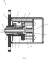
FIG. 2 is a cross-sectional view of the pipeline pressure monitoring device according to the embodiment of the present invention. - For the technical means, creative features, objects and effects achieved by the present invention to be understood easily, the following embodiments will specifically illustrate the pipeline pressure monitoring device of the present invention, with reference to the accompanying drawings.
- As shown in
FIG. 1 andFIG. 2 , the pipelinepressure monitoring device 100 comprises ahousing 10, avent nozzle 20, afirst circuit board 30, apressure sensor 40, asliding sleeve 50, anelastic member 60, amagnetic block 70, asecond circuit board 80, and aposition sensor 90. - One side of the
housing 10 has amounting hole 11. - The
vent nozzle 20 has avent 21. Thevent nozzle 20 is installed in thehousing 10. One end of thevent nozzle 20 extends out of thehousing 10 via themounting hole 11. Afirst stop block 22 is provided on thevent nozzle 20. - The
first circuit board 30 is installed in thehousing 10. Thepressure sensor 40 is configured to detect the pressure inside thevent nozzle 20. Thepressure sensor 40 is installed on thefirst circuit board 30 and connected to thefirst circuit board 30. Thepressure sensor 40 is matched with one end of thevent 21 facing the inside of thehousing 10. Thepressure sensor 40 is installed at the end of thevent 21 facing the inside of thehousing 10 to block the end. After thevent nozzle 20 is installed on thepressure sensor 40, thefirst circuit board 30 and thepressure sensor 40 play a role in fixing thevent nozzle 20. - In this embodiment, a
sealing ring 41 is provided between thepressure sensor 40 and thevent nozzle 20. - The
sliding sleeve 50 is installed in themounting hole 11 in a sliding manner. Thesliding sleeve 50 has a throughhole 51. Thesliding sleeve 50 is sleeved on thevent nozzle 20 via the throughhole 51. Alimit member 52 is provided on thesliding sleeve 50. Thelimit member 52 is located inside thehousing 10, and is configured to prevent the slidingsleeve 50 from sliding out of themounting hole 11. - In the present embodiment, a
bushing 53 is provided between thesliding sleeve 50 and thevent nozzle 20. Thebushing 53 is fixed on thethrough hole 51 of thesliding sleeve 50. Thebushing 53 is slidably sleeved on thevent nozzle 20. - In this embodiment, the cross-section of the other end of the
vent nozzle 20 facing the outside of thehousing 10 gradually decreases toward the outside of thehousing 10, and the cross-section of thevent 21 is constant, that is, referring toFIG. 2 , the wall at the left end of thevent nozzle 20 gradually becomes thinner towards the left. Specifically, the end of thevent nozzle 20 facing the outside of thehousing 10 is a hollow cylinder. The outer diameter of the hollow cylinder gradually decreases toward the outside of thehousing 10, while the inner diameter is constant. A section of thevent nozzle 20 that is gradually tapered does not contact the throughhole 51. Thebushing 52 is located on one side of the throughhole 51 facing the inside of thehousing 10. Theelastic member 60 is sleeved on thevent nozzle 20 and sandwiched between thefirst stop block 22 and thesliding sleeve 50. When no consumable connector is installed on thevent 20, theelastic member 60 is in a free or slightly compressed state. When theelastic member 60 is in a free state, both ends of theelastic member 60 are in contact with thefirst stop block 22 and thesliding sleeve 50, respectively. - In this embodiment, the
elastic member 60 is a spring. - The
magnetic block 70 is installed on the slidingsleeve 50. Specifically, themagnetic block 70 is mounted on the slidingsleeve 50 inside thehousing 10. - The
second circuit board 80 is installed in thehousing 10, and is connected to thefirst circuit board 30. - The
position sensor 90 is installed on thesecond circuit board 80, and is connected to thesecond circuit board 80. The installation position of theposition sensor 90 meets that: after the consumable connector is installed on thevent nozzle 20, the distance that the slidingsleeve 50 slides toward the inside of thehousing 10 is just enough to make themagnetic block 70 move into the detection area of theposition sensor 90. Specifically, theposition sensor 90 is Hall sensor. When themagnetic block 70 moves into the detection area of theposition sensor 90, theposition sensor 90 outputs 1; when themagnetic block 70 is not in the detection area of theposition sensor 90, theposition sensor 90 outputs 0. - Both the
first circuit board 30 and thesecond circuit board 80 are connected with the external equipment, and are configured to send the detected pressure information and the signal detected by theposition sensor 90 to the external equipment, and the detection data is displayed by the external equipment. - When the consumable connector is installed on the
vent nozzle 30, the consumable connector will push the slidingsleeve 50 to move toward the inside of thehousing 10 and compress theelastic member 60. Themagnetic block 70 moves toward the inside of thehousing 10 along with the slidingsleeve 50. After the consumable connector is installed on thevent nozzle 30, themagnetic block 70 moves to the detection area of theposition sensor 90. After themagnetic block 70 is sensed by theposition sensor 90, the output signal changes. Therefore, it can be judged whether the consumable connector is installed in thevent nozzle 30 correctly. Thepressure sensor 40 detects the pressure of the gas in thevent nozzle 30, so that the pressure of the gas in the pipeline of the consumable connector connected to thevent nozzle 30 and the equipment connected to the consumable connector can be obtained. After the consumable connector is taken out, under the elastic force of theelastic member 60, the slidingsleeve 50 is returned. - The above embodiment is a preferred embodiment of the present invention, and is not intended to limit the protection scope of the present invention.
Claims (5)
- A pipeline pressure monitoring device (100), comprising:a housing (10), one side of the housing (10) having a mounting hole (11);a vent nozzle (20), the vent nozzle (20) having a vent (21), the vent nozzle (20) being installed in the housing (10), one end of the vent nozzle (20) extending out of the housing (10) via the mounting hole (11), a first stop block (22) being provided on the vent nozzle (20);a first circuit board (30), installed in the housing (10);a pressure sensor (40), configured to detect pressure inside the vent nozzle (20), the pressure sensor (40) being installed on the first circuit board (30) and connected to the first circuit board (30), the pressure sensor (40) being matched with another end of the vent nozzle (20) facing an inside of the housing (10), the pressure sensor (40) being installed at the another end of the vent nozzle (20) facing the inside of the housing (10) to block the another end;a sliding sleeve (50), installed in the mounting hole (11) in a sliding manner, the sliding sleeve (50) having a through hole (51), the sliding sleeve (50) being sleeved on the vent nozzle (20) via the through hole (51), a limit member (52) being provided on the sliding sleeve (50), the limit member (52) being located inside the housing (10);an elastic member (60), sleeved on the vent nozzle (20) and sandwiched between the first stop block (22) and the sliding sleeve (50);a magnetic block (70), installed on the sliding sleeve (50);a second circuit board (80), installed in the housing (10) and connected to the first circuit board (30); anda position sensor (90), installed on the second circuit board (80) and connected to the second circuit board (80), wherein the installation position of the position sensor (90) meets that: after a consumable connector is installed on the vent nozzle (20), the distance that the sliding sleeve (50) slides toward the inside of the housing (10) is just enough to make the magnetic block (70) move into a detection area of the position sensor (90).
- The pipeline pressure monitoring device (100) as claimed in claim 1, wherein a sealing ring (41) is provided between the pressure sensor (40) and the vent nozzle (20).
- The pipeline pressure monitoring device (100) as claimed in claim 1, wherein the elastic member (60) is a spring.
- The pipeline pressure monitoring device (100) as claimed in claim 1, wherein a bushing (53) is provided between the sliding sleeve (50) and the vent nozzle (20), the bushing (53) is fixed on the through hole (51) of the sliding sleeve (50), and the bushing (53) is slidably sleeved on the vent nozzle (20).
- The pipeline pressure monitoring device (100) as claimed in claim 4, wherein the cross-section of the end of the vent nozzle (20) facing an outside of the housing (10) gradually decreases toward the outside of the housing (10), the cross-section of the vent (21) is constant, a section of the vent nozzle (20) that is gradually tapered does not contact the through hole (51), and the bushing (52) is located on one side of the through hole (51) facing the inside of the housing (10).
Applications Claiming Priority (2)
| Application Number | Priority Date | Filing Date | Title |
|---|---|---|---|
| CN202011287588.5A CN112304486A (en) | 2020-11-17 | 2020-11-17 | A pipeline pressure monitoring device |
| PCT/CN2020/141900 WO2022105036A1 (en) | 2020-11-17 | 2020-12-31 | Pipeline pressure monitoring device |
Publications (4)
| Publication Number | Publication Date |
|---|---|
| EP4242617A1 true EP4242617A1 (en) | 2023-09-13 |
| EP4242617A4 EP4242617A4 (en) | 2024-04-10 |
| EP4242617C0 EP4242617C0 (en) | 2025-07-16 |
| EP4242617B1 EP4242617B1 (en) | 2025-07-16 |
Family
ID=74336127
Family Applications (1)
| Application Number | Title | Priority Date | Filing Date |
|---|---|---|---|
| EP20962327.1A Active EP4242617B1 (en) | 2020-11-17 | 2020-12-31 | Pipeline pressure monitoring device |
Country Status (5)
| Country | Link |
|---|---|
| US (1) | US12399075B2 (en) |
| EP (1) | EP4242617B1 (en) |
| CN (1) | CN112304486A (en) |
| HU (1) | HUE073419T2 (en) |
| WO (1) | WO2022105036A1 (en) |
Families Citing this family (1)
| Publication number | Priority date | Publication date | Assignee | Title |
|---|---|---|---|---|
| CN116857529B (en) * | 2023-06-28 | 2026-04-14 | 浙江中物合数字科技集团有限公司 | Pipeline pressure sensor and installation method thereof |
Family Cites Families (17)
| Publication number | Priority date | Publication date | Assignee | Title |
|---|---|---|---|---|
| FR2664977B1 (en) * | 1990-07-23 | 1992-10-09 | Asulab Sa | DEVICE FOR DETECTING AN OVERPRESSURE INSIDE A PIPE AND PUMP PROVIDED WITH SUCH A DEVICE. |
| EP1591767B1 (en) * | 2003-01-30 | 2011-03-23 | JMS Co., Ltd. | Pressure detector |
| CN101349604B (en) | 2008-09-05 | 2010-12-29 | 广东联塑科技实业有限公司 | Apparatus and method for testing and monitoring pipe real time pressure |
| US8002748B2 (en) * | 2009-04-24 | 2011-08-23 | Kyphon Sarl | Digital syringe with compensation control |
| CN101786450A (en) | 2010-02-26 | 2010-07-28 | 吉林大学 | Vehicle brake pipeline pressure monitor and early warning system for |
| WO2015095239A1 (en) * | 2013-12-18 | 2015-06-25 | Optiscan Biomedical Corporation | Systems and methods for detecting leaks |
| CN106415229B (en) * | 2014-03-27 | 2020-06-30 | 西铁城精密器件株式会社 | Combustion pressure sensor and method for manufacturing same |
| KR20180018693A (en) * | 2015-06-11 | 2018-02-21 | 노드슨 코포레이션 | Cartridge-type fluid dispensing device |
| CN205843873U (en) | 2016-07-22 | 2016-12-28 | 四川南格尔生物科技有限公司 | A kind of pressure monitor |
| TWI615741B (en) * | 2017-01-06 | 2018-02-21 | 致伸科技股份有限公司 | Mouse with barometric sensing button |
| CN206670839U (en) * | 2017-01-12 | 2017-11-24 | 董稳 | A kind of medical pressure detector mechanical structure |
| CN109203872B (en) * | 2017-07-06 | 2025-01-24 | 深圳市道通科技股份有限公司 | A tire pressure sensor |
| CN107823741A (en) | 2017-10-27 | 2018-03-23 | 冯新庆 | A kind of pressure detecting interface for extracorporeal circulation of blood pipeline |
| CN110595665B (en) | 2019-09-09 | 2025-01-14 | 上海钧嵌传感技术有限公司 | Pressure detection sensor and detection method |
| CN110793709B (en) | 2019-12-04 | 2021-07-23 | 四川南格尔生物科技有限公司 | Pressure monitoring device |
| CN212830585U (en) | 2020-07-07 | 2021-03-30 | 杭州鼎玺智能技术有限公司 | Oil tank and pipeline pressure monitoring system |
| CN213364112U (en) * | 2020-11-17 | 2021-06-04 | 赛若麦得(上海)生物技术有限公司 | Pipeline pressure monitoring device |
-
2020
- 2020-11-17 CN CN202011287588.5A patent/CN112304486A/en active Pending
- 2020-12-31 WO PCT/CN2020/141900 patent/WO2022105036A1/en not_active Ceased
- 2020-12-31 US US18/037,485 patent/US12399075B2/en active Active
- 2020-12-31 HU HUE20962327A patent/HUE073419T2/en unknown
- 2020-12-31 EP EP20962327.1A patent/EP4242617B1/en active Active
Also Published As
| Publication number | Publication date |
|---|---|
| EP4242617C0 (en) | 2025-07-16 |
| EP4242617A4 (en) | 2024-04-10 |
| HUE073419T2 (en) | 2026-01-28 |
| US20240011860A1 (en) | 2024-01-11 |
| EP4242617B1 (en) | 2025-07-16 |
| CN112304486A (en) | 2021-02-02 |
| WO2022105036A1 (en) | 2022-05-27 |
| US12399075B2 (en) | 2025-08-26 |
Similar Documents
| Publication | Publication Date | Title |
|---|---|---|
| CN107710523B (en) | Connector Engagement Sensing Mechanism | |
| CN107810388B (en) | Modular sealing device with fault detection unit | |
| US12399075B2 (en) | Pipeline pressure monitoring device | |
| CA2514762A1 (en) | Pressure detector and pressure detecting method | |
| CN107636572A (en) | Pressure-detecting device and stylus | |
| US20210033797A1 (en) | Connector Engagement Sensing Mechanism | |
| CN110692170B (en) | Connector engagement sensing mechanism | |
| JP2016198831A (en) | Pressure air measuring device and machine tool system using the same | |
| EP3229004B1 (en) | Pressure sensor | |
| CN212030789U (en) | Foot end ground contact force detection device and robot comprising same | |
| CN213364112U (en) | Pipeline pressure monitoring device | |
| US5945603A (en) | Vibration detector adapted for use in a vibration measuring device | |
| US10048149B2 (en) | Relative pressure sensor | |
| EP4737874A1 (en) | Pressure sensor | |
| US6701773B2 (en) | Plug-in adapter for gas sampling | |
| CN103026184B (en) | Oil level indicator for screw compressor | |
| CN217410817U (en) | TIP head liquid-transfering component | |
| CN112757051A (en) | Detection device | |
| US10989341B2 (en) | Fluid connectors with modular connection state sensors | |
| CN223964692U (en) | Pneumatic structure | |
| CN222992338U (en) | Relief valve early warning device | |
| CN220637652U (en) | Portable digital display device | |
| CN222965653U (en) | Electronic pen structure | |
| CN217155338U (en) | Start-stop sensor | |
| CN221148767U (en) | Water level monitoring detection rod mounting head |
Legal Events
| Date | Code | Title | Description |
|---|---|---|---|
| STAA | Information on the status of an ep patent application or granted ep patent |
Free format text: STATUS: THE INTERNATIONAL PUBLICATION HAS BEEN MADE |
|
| PUAI | Public reference made under article 153(3) epc to a published international application that has entered the european phase |
Free format text: ORIGINAL CODE: 0009012 |
|
| STAA | Information on the status of an ep patent application or granted ep patent |
Free format text: STATUS: REQUEST FOR EXAMINATION WAS MADE |
|
| 17P | Request for examination filed |
Effective date: 20230606 |
|
| AK | Designated contracting states |
Kind code of ref document: A1 Designated state(s): AL AT BE BG CH CY CZ DE DK EE ES FI FR GB GR HR HU IE IS IT LI LT LU LV MC MK MT NL NO PL PT RO RS SE SI SK SM TR |
|
| DAV | Request for validation of the european patent (deleted) | ||
| DAX | Request for extension of the european patent (deleted) | ||
| STAA | Information on the status of an ep patent application or granted ep patent |
Free format text: STATUS: EXAMINATION IS IN PROGRESS |
|
| A4 | Supplementary search report drawn up and despatched |
Effective date: 20240313 |
|
| RIC1 | Information provided on ipc code assigned before grant |
Ipc: G01L 19/14 20060101ALI20240306BHEP Ipc: G01L 19/00 20060101ALI20240306BHEP Ipc: G01L 11/00 20060101AFI20240306BHEP |
|
| 17Q | First examination report despatched |
Effective date: 20240327 |
|
| GRAP | Despatch of communication of intention to grant a patent |
Free format text: ORIGINAL CODE: EPIDOSNIGR1 |
|
| STAA | Information on the status of an ep patent application or granted ep patent |
Free format text: STATUS: GRANT OF PATENT IS INTENDED |
|
| INTG | Intention to grant announced |
Effective date: 20250210 |
|
| GRAS | Grant fee paid |
Free format text: ORIGINAL CODE: EPIDOSNIGR3 |
|
| GRAA | (expected) grant |
Free format text: ORIGINAL CODE: 0009210 |
|
| STAA | Information on the status of an ep patent application or granted ep patent |
Free format text: STATUS: THE PATENT HAS BEEN GRANTED |
|
| AK | Designated contracting states |
Kind code of ref document: B1 Designated state(s): AL AT BE BG CH CY CZ DE DK EE ES FI FR GB GR HR HU IE IS IT LI LT LU LV MC MK MT NL NO PL PT RO RS SE SI SK SM TR |
|
| REG | Reference to a national code |
Ref country code: GB Ref legal event code: FG4D |
|
| REG | Reference to a national code |
Ref country code: CH Ref legal event code: EP |
|
| REG | Reference to a national code |
Ref country code: DE Ref legal event code: R096 Ref document number: 602020054846 Country of ref document: DE |
|
| REG | Reference to a national code |
Ref country code: IE Ref legal event code: FG4D |
|
| U01 | Request for unitary effect filed |
Effective date: 20250812 |
|
| U07 | Unitary effect registered |
Designated state(s): AT BE BG DE DK EE FI FR IT LT LU LV MT NL PT RO SE SI Effective date: 20250821 |
|
| PG25 | Lapsed in a contracting state [announced via postgrant information from national office to epo] |
Ref country code: IS Free format text: LAPSE BECAUSE OF FAILURE TO SUBMIT A TRANSLATION OF THE DESCRIPTION OR TO PAY THE FEE WITHIN THE PRESCRIBED TIME-LIMIT Effective date: 20251116 |
|
| PGFP | Annual fee paid to national office [announced via postgrant information from national office to epo] |
Ref country code: GB Payment date: 20251209 Year of fee payment: 6 |
|
| PG25 | Lapsed in a contracting state [announced via postgrant information from national office to epo] |
Ref country code: NO Free format text: LAPSE BECAUSE OF FAILURE TO SUBMIT A TRANSLATION OF THE DESCRIPTION OR TO PAY THE FEE WITHIN THE PRESCRIBED TIME-LIMIT Effective date: 20251016 |
|
| U20 | Renewal fee for the european patent with unitary effect paid |
Year of fee payment: 6 Effective date: 20251210 |
|
| PG25 | Lapsed in a contracting state [announced via postgrant information from national office to epo] |
Ref country code: HR Free format text: LAPSE BECAUSE OF FAILURE TO SUBMIT A TRANSLATION OF THE DESCRIPTION OR TO PAY THE FEE WITHIN THE PRESCRIBED TIME-LIMIT Effective date: 20250716 |
|
| PGFP | Annual fee paid to national office [announced via postgrant information from national office to epo] |
Ref country code: HU Payment date: 20251212 Year of fee payment: 6 |
|
| PG25 | Lapsed in a contracting state [announced via postgrant information from national office to epo] |
Ref country code: GR Free format text: LAPSE BECAUSE OF FAILURE TO SUBMIT A TRANSLATION OF THE DESCRIPTION OR TO PAY THE FEE WITHIN THE PRESCRIBED TIME-LIMIT Effective date: 20251017 |
|
| PGFP | Annual fee paid to national office [announced via postgrant information from national office to epo] |
Ref country code: CZ Payment date: 20251215 Year of fee payment: 6 |
|
| PG25 | Lapsed in a contracting state [announced via postgrant information from national office to epo] |
Ref country code: PL Free format text: LAPSE BECAUSE OF FAILURE TO SUBMIT A TRANSLATION OF THE DESCRIPTION OR TO PAY THE FEE WITHIN THE PRESCRIBED TIME-LIMIT Effective date: 20250716 |
|
| PG25 | Lapsed in a contracting state [announced via postgrant information from national office to epo] |
Ref country code: RS Free format text: LAPSE BECAUSE OF FAILURE TO SUBMIT A TRANSLATION OF THE DESCRIPTION OR TO PAY THE FEE WITHIN THE PRESCRIBED TIME-LIMIT Effective date: 20251016 |
|
| REG | Reference to a national code |
Ref country code: HU Ref legal event code: AG4A Ref document number: E073419 Country of ref document: HU |
|
| PG25 | Lapsed in a contracting state [announced via postgrant information from national office to epo] |
Ref country code: ES Free format text: LAPSE BECAUSE OF FAILURE TO SUBMIT A TRANSLATION OF THE DESCRIPTION OR TO PAY THE FEE WITHIN THE PRESCRIBED TIME-LIMIT Effective date: 20250716 |
|
| REG | Reference to a national code |
Ref country code: CH Ref legal event code: W10 Free format text: ST27 STATUS EVENT CODE: U-0-0-W10-W00 (AS PROVIDED BY THE NATIONAL OFFICE) Effective date: 20260211 |
|
| RAP2 | Party data changed (patent owner data changed or rights of a patent transferred) |
Owner name: SCINOMED LIMITED |
|
| U1K | Transfer of rights of the unitary patent after the registration of the unitary effect |
Owner name: SCINOMED LIMITED; GB |
|
| PG25 | Lapsed in a contracting state [announced via postgrant information from national office to epo] |
Ref country code: SM Free format text: LAPSE BECAUSE OF FAILURE TO SUBMIT A TRANSLATION OF THE DESCRIPTION OR TO PAY THE FEE WITHIN THE PRESCRIBED TIME-LIMIT Effective date: 20250716 |
|
| REG | Reference to a national code |
Ref country code: GB Ref legal event code: 732E Free format text: REGISTERED BETWEEN 20260312 AND 20260318 |
|
| PG25 | Lapsed in a contracting state [announced via postgrant information from national office to epo] |
Ref country code: SK Free format text: LAPSE BECAUSE OF FAILURE TO SUBMIT A TRANSLATION OF THE DESCRIPTION OR TO PAY THE FEE WITHIN THE PRESCRIBED TIME-LIMIT Effective date: 20250716 |