EP4242579A1 - Optical interferometric range sensor - Google Patents
Optical interferometric range sensor Download PDFInfo
- Publication number
- EP4242579A1 EP4242579A1 EP23155955.0A EP23155955A EP4242579A1 EP 4242579 A1 EP4242579 A1 EP 4242579A1 EP 23155955 A EP23155955 A EP 23155955A EP 4242579 A1 EP4242579 A1 EP 4242579A1
- Authority
- EP
- European Patent Office
- Prior art keywords
- light
- sensor head
- head
- sensor
- optical
- Prior art date
- Legal status (The legal status is an assumption and is not a legal conclusion. Google has not performed a legal analysis and makes no representation as to the accuracy of the status listed.)
- Granted
Links
Images











Classifications
-
- G—PHYSICS
- G01—MEASURING; TESTING
- G01B—MEASURING LENGTH, THICKNESS OR SIMILAR LINEAR DIMENSIONS; MEASURING ANGLES; MEASURING AREAS; MEASURING IRREGULARITIES OF SURFACES OR CONTOURS
- G01B9/00—Measuring instruments characterised by the use of optical techniques
- G01B9/02—Interferometers
- G01B9/02015—Interferometers characterised by the beam path configuration
- G01B9/02027—Two or more interferometric channels or interferometers
-
- G—PHYSICS
- G01—MEASURING; TESTING
- G01B—MEASURING LENGTH, THICKNESS OR SIMILAR LINEAR DIMENSIONS; MEASURING ANGLES; MEASURING AREAS; MEASURING IRREGULARITIES OF SURFACES OR CONTOURS
- G01B9/00—Measuring instruments characterised by the use of optical techniques
- G01B9/02—Interferometers
- G01B9/02083—Interferometers characterised by particular signal processing and presentation
- G01B9/02084—Processing in the Fourier or frequency domain when not imaged in the frequency domain
-
- G—PHYSICS
- G01—MEASURING; TESTING
- G01S—RADIO DIRECTION-FINDING; RADIO NAVIGATION; DETERMINING DISTANCE OR VELOCITY BY USE OF RADIO WAVES; LOCATING OR PRESENCE-DETECTING BY USE OF THE REFLECTION OR RERADIATION OF RADIO WAVES; ANALOGOUS ARRANGEMENTS USING OTHER WAVES
- G01S17/00—Systems using the reflection or reradiation of electromagnetic waves other than radio waves, e.g. lidar systems
- G01S17/02—Systems using the reflection of electromagnetic waves other than radio waves
- G01S17/06—Systems determining position data of a target
- G01S17/08—Systems determining position data of a target for measuring distance only
- G01S17/32—Systems determining position data of a target for measuring distance only using transmission of continuous waves, whether amplitude-, frequency-, or phase-modulated, or unmodulated
- G01S17/36—Systems determining position data of a target for measuring distance only using transmission of continuous waves, whether amplitude-, frequency-, or phase-modulated, or unmodulated with phase comparison between the received signal and the contemporaneously transmitted signal
-
- G—PHYSICS
- G01—MEASURING; TESTING
- G01B—MEASURING LENGTH, THICKNESS OR SIMILAR LINEAR DIMENSIONS; MEASURING ANGLES; MEASURING AREAS; MEASURING IRREGULARITIES OF SURFACES OR CONTOURS
- G01B11/00—Measuring arrangements characterised by the use of optical techniques
- G01B11/02—Measuring arrangements characterised by the use of optical techniques for measuring length, width or thickness
- G01B11/026—Measuring arrangements characterised by the use of optical techniques for measuring length, width or thickness by measuring distance between sensor and object
-
- G—PHYSICS
- G01—MEASURING; TESTING
- G01B—MEASURING LENGTH, THICKNESS OR SIMILAR LINEAR DIMENSIONS; MEASURING ANGLES; MEASURING AREAS; MEASURING IRREGULARITIES OF SURFACES OR CONTOURS
- G01B11/00—Measuring arrangements characterised by the use of optical techniques
- G01B11/14—Measuring arrangements characterised by the use of optical techniques for measuring distance or clearance between spaced objects or spaced apertures
-
- G—PHYSICS
- G01—MEASURING; TESTING
- G01B—MEASURING LENGTH, THICKNESS OR SIMILAR LINEAR DIMENSIONS; MEASURING ANGLES; MEASURING AREAS; MEASURING IRREGULARITIES OF SURFACES OR CONTOURS
- G01B9/00—Measuring instruments characterised by the use of optical techniques
- G01B9/02—Interferometers
- G01B9/02001—Interferometers characterised by controlling or generating intrinsic radiation properties
- G01B9/02002—Interferometers characterised by controlling or generating intrinsic radiation properties using two or more frequencies
- G01B9/02004—Interferometers characterised by controlling or generating intrinsic radiation properties using two or more frequencies using frequency scans
-
- G—PHYSICS
- G01—MEASURING; TESTING
- G01B—MEASURING LENGTH, THICKNESS OR SIMILAR LINEAR DIMENSIONS; MEASURING ANGLES; MEASURING AREAS; MEASURING IRREGULARITIES OF SURFACES OR CONTOURS
- G01B9/00—Measuring instruments characterised by the use of optical techniques
- G01B9/02—Interferometers
- G01B9/02015—Interferometers characterised by the beam path configuration
-
- G—PHYSICS
- G01—MEASURING; TESTING
- G01B—MEASURING LENGTH, THICKNESS OR SIMILAR LINEAR DIMENSIONS; MEASURING ANGLES; MEASURING AREAS; MEASURING IRREGULARITIES OF SURFACES OR CONTOURS
- G01B9/00—Measuring instruments characterised by the use of optical techniques
- G01B9/02—Interferometers
- G01B9/02055—Reduction or prevention of errors; Testing; Calibration
- G01B9/02056—Passive reduction of errors
- G01B9/02057—Passive reduction of errors by using common path configuration, i.e. reference and object path almost entirely overlapping
-
- G—PHYSICS
- G01—MEASURING; TESTING
- G01B—MEASURING LENGTH, THICKNESS OR SIMILAR LINEAR DIMENSIONS; MEASURING ANGLES; MEASURING AREAS; MEASURING IRREGULARITIES OF SURFACES OR CONTOURS
- G01B9/00—Measuring instruments characterised by the use of optical techniques
- G01B9/02—Interferometers
- G01B9/02055—Reduction or prevention of errors; Testing; Calibration
- G01B9/02062—Active error reduction, i.e. varying with time
- G01B9/02067—Active error reduction, i.e. varying with time by electronic control systems, i.e. using feedback acting on optics or light
- G01B9/02069—Synchronization of light source or manipulator and detector
-
- G—PHYSICS
- G01—MEASURING; TESTING
- G01B—MEASURING LENGTH, THICKNESS OR SIMILAR LINEAR DIMENSIONS; MEASURING ANGLES; MEASURING AREAS; MEASURING IRREGULARITIES OF SURFACES OR CONTOURS
- G01B9/00—Measuring instruments characterised by the use of optical techniques
- G01B9/02—Interferometers
- G01B9/0209—Low-coherence interferometers
-
- G—PHYSICS
- G01—MEASURING; TESTING
- G01S—RADIO DIRECTION-FINDING; RADIO NAVIGATION; DETERMINING DISTANCE OR VELOCITY BY USE OF RADIO WAVES; LOCATING OR PRESENCE-DETECTING BY USE OF THE REFLECTION OR RERADIATION OF RADIO WAVES; ANALOGOUS ARRANGEMENTS USING OTHER WAVES
- G01S7/00—Details of systems according to groups G01S13/00, G01S15/00, G01S17/00
- G01S7/48—Details of systems according to groups G01S13/00, G01S15/00, G01S17/00 of systems according to group G01S17/00
- G01S7/481—Constructional features, e.g. arrangements of optical elements
-
- G—PHYSICS
- G01—MEASURING; TESTING
- G01S—RADIO DIRECTION-FINDING; RADIO NAVIGATION; DETERMINING DISTANCE OR VELOCITY BY USE OF RADIO WAVES; LOCATING OR PRESENCE-DETECTING BY USE OF THE REFLECTION OR RERADIATION OF RADIO WAVES; ANALOGOUS ARRANGEMENTS USING OTHER WAVES
- G01S7/00—Details of systems according to groups G01S13/00, G01S15/00, G01S17/00
- G01S7/48—Details of systems according to groups G01S13/00, G01S15/00, G01S17/00 of systems according to group G01S17/00
- G01S7/481—Constructional features, e.g. arrangements of optical elements
- G01S7/4814—Constructional features, e.g. arrangements of optical elements of transmitters alone
-
- G—PHYSICS
- G02—OPTICS
- G02B—OPTICAL ELEMENTS, SYSTEMS OR APPARATUS
- G02B6/00—Light guides; Structural details of arrangements comprising light guides and other optical elements, e.g. couplings
- G02B6/24—Coupling light guides
- G02B6/26—Optical coupling means
- G02B6/262—Optical details of coupling light into, or out of, or between fibre ends, e.g. special fibre end shapes or associated optical elements
-
- G—PHYSICS
- G01—MEASURING; TESTING
- G01B—MEASURING LENGTH, THICKNESS OR SIMILAR LINEAR DIMENSIONS; MEASURING ANGLES; MEASURING AREAS; MEASURING IRREGULARITIES OF SURFACES OR CONTOURS
- G01B2210/00—Aspects not specifically covered by any group under G01B, e.g. of wheel alignment, caliper-like sensors
- G01B2210/60—Unique sensor identification
Definitions
- the present invention relates to an optical interferometric range sensor.
- a known optical range sensor includes an optical interferometric range sensor that generates, from light emitted from a wavelength swept light source, interference light based on reference light and measurement light and measures the distance to a measurement target based on the interference light.
- Another known optical interferometric range sensor irradiates a measurement target with multiple beams and measures the measurement target with high accuracy.
- Patent Literature 1 describes an optical measurement device that causes a returning beam component of a reference beam reflected from the end faces of multiple optical fibers to coherently interfere with a reflected component of a measurement beam reflected from a surface of a measurement target to obtain stable measurement results.
- Patent Literature 1 Japanese Patent No. 2686124
- the known optical interferometric range sensor irradiating a measurement target with multiple beams may include multiple single spot heads each emitting a single beam or including a single multi-spot head that emits multiple beams.
- the use of the multi-spot head may place a user in an insecure situation when multiple laser beams are emitted to a predetermined area. For example, safety based on safety standards for laser beams may be compromised. Although the amount of laser beams to be emitted may be reduced to increase safety, the use of multiple single spot heads located at predetermined intervals may lower the measurement accuracy due to the small amount of laser beams being emitted.
- One or more aspects of the present invention are directed to an optical interferometric range sensor that can adjust the amount of light as appropriate for a sensor head.
- An optical interferometric range sensor includes a light source that emits light with a changing wavelength, a light splitter that splits the light emitted from the light source into a plurality of beams to be incident on a plurality of spots, an interferometer that generates, for each of the plurality of beams of the split light incident on a corresponding spot of the plurality of spots, interference light based on measurement light emitted from a sensor head to a measurement target and reflected from the measurement target and reference light traveling on an optical path at least partially different from an optical path of the measurement light, a light receiver that receives the interference light from the interferometer to convert the interference light to an electric signal, a processor that calculates a distance from the sensor head to the measurement target based on the electric signal resulting from conversion performed by the light receiver, an identifier that identifies the sensor head based on a beat signal generated by the interferometer, and a light adjuster that adjusts an amount of light to be emitted from the sensor head
- the identifier identifies the sensor head based on the beat signal generated by the interferometer, and the light adjuster adjusts, based on the sensor head identified by the identifier, the amount of light emitted from the sensor head to the measurement target.
- the amount of light incident on the measurement target to be adjusted as appropriate for the sensor head, thus allowing the measurement distance from the sensor head to the measurement target to be measured with high accuracy while satisfying the safety standards for laser beam irradiation. This reduces the user work of, for example, identifying the type of sensor head and manually setting the corresponding amount of light in each measurement operation.
- the sensor head may include a single spot head or a multi-spot head.
- the optical interferometric range sensor can identify the sensor head being used as multiple single spot heads or a single multi-spot head for multiple spots and adjust the amount of light as appropriate for each head.
- the light adjuster may adjust an amount of light to be transmitted to the light splitter to be less than or equal to a predetermined value when the identifier identifies the sensor head.
- the light adjuster adjusts the amount of light to less than or equal to the predetermined value to satisfy the safety standards for laser beams.
- the predetermined value may be an amount of light adjusted for the sensor head identified as a multi-spot head by the identifier.
- the light adjuster adjusts the amount of light to the amount for a sensor head being a multi-spot head.
- the safety standards for laser beams can be sufficiently satisfied for the sensor head that may be a multi-spot head.
- the identifier may identify the sensor head based on at least one of a peak frequency of the beat signal or the number of peaks in the beat signal.
- the identifier identifies the sensor head based on at least one of the peak frequency of the beat signal or the number of peaks in the beat signal, thus facilitating identification of the sensor head without causing the user to determine the type of sensor head.
- the beat signal may result from a portion of the light emitted from the light source and received by the interferometer being reflected from a component of the interferometer including a reflective surface.
- the beat signal results from a portion of the light emitted from the light source and received by the interferometer being reflected from the component of the interferometer including the reflective surface, thus facilitating identification of the sensor head without causing the user to determine the type of sensor head.
- the reflective surface may be located inside the sensor head.
- the reflective surface is located inside the sensor head. This reduces the user work including determination and preparation associated with the sensor head, other than attaching the sensor head, thus facilitating identification of the sensor head.
- the reflective surface may be located on an objective lens included in the sensor head.
- the reflective surface is located on the objective lens included in the sensor head, thus eliminating preparation of, for example, a separate component and facilitating identification of the sensor head.
- the reflective surface may be located on a collimating lens included in the sensor head.
- the reflective surface is located on the collimating lens included in the sensor head, thus eliminating preparation of, for example, a separate component and facilitating identification of the sensor head.
- the reflective surface may be located inside an optical fiber that guides the light emitted from the light source to the sensor head.
- the reflective surface is located inside the optical fiber that guides light emitted from the light source to the sensor head, thus facilitating identification of the sensor head without a reflective surface in the sensor head.
- optical interferometric range sensor according to the above aspects of the present invention can adjust the amount of light as appropriate for the sensor head.
- FIG. 1 is a schematic external view of a displacement sensor 10 according to the embodiment of the present disclosure.
- the displacement sensor 10 includes a sensor head 20 and a controller 30 to measure the displacement of a measurement target T (distance to the measurement target T).
- the sensor head 20 and the controller 30 are connected with an optical fiber 40.
- An objective lens 21 is attached to the sensor head 20.
- the controller 30 includes a display 31, a setting unit 32, an external interface (I/F) 33, an optical fiber connector 34, an external storage 35, and an internal measurement processor 36.
- the sensor head 20 irradiates the measurement target T with light output from the controller 30 and receives reflected light from the measurement target T.
- the sensor head 20 includes a reference surface inside that reflects light output from the controller 30 and received through the optical fiber 40 and causes such light to interfere with the reflected light from the measurement target T described above.
- the objective lens 21 attached to the sensor head 20 is detachable.
- the objective lens 21 is replaceable with another objective lens having a focal length appropriate for the distance between the sensor head 20 and the measurement target T, or is a variable-focus objective lens.
- the sensor head 20, the measurement target T, or both may be positioned to have the measurement target T appropriately being within the measurement area of the displacement sensor 10 by irradiating the measurement target T with guide light (visible light).
- the optical fiber 40 is connected to the optical fiber connector 34 on the controller 30 and extends to connect the controller 30 and the sensor head 20.
- the optical fiber 40 thus guides light emitted from the controller 30 to the sensor head 20 and returning light from the sensor head 20 to the controller 30.
- the optical fiber 40 is detachable from the sensor head 20 and the controller 30.
- the optical fiber may have any length, thickness, and characteristics.
- the display 31 is, for example, a liquid crystal display or an organic electroluminescent (EL) display.
- the display 31 displays the setting values of the displacement sensor 10, the amount of returning light received from the sensor head 20, and measurement results measured by the displacement sensor 10, such as the displacement of the measurement target T (distance to the measurement target T).
- the setting unit 32 receives settings associated with measurement of the measurement target T through user operations performed on mechanical buttons or a touchscreen. All or some of the associated settings may be preset or set through an external connection device (not shown) connected to the external I/F 33.
- the external connection device may be connected with a wire or wirelessly through a network.
- the external I/F 33 includes, for example, Ethernet (registered trademark), Recommended Standard (RS) 232C, and analog output.
- the external I/F 33 may be connected to an external connection device to allow the associated settings to be input through the external connection device or to output, for example, measurement results measured by the displacement sensor 10 to the external connection device.
- the controller 30 may import data stored in the external storage 35 to perform the settings associated with measurement of the measurement target T.
- the external storage 35 is, for example, an auxiliary storage, such as a universal serial bus (USB) memory, which prestores settings associated with measurement of the measurement target T.
- USB universal serial bus
- the measurement processor 36 in the controller 30 includes, for example, a wavelength swept light source that emits light with continuously changing wavelengths, a light receiving element that receives returning light from the sensor head 20 to convert the received light to an electric signal, and a signal processing circuit that processes the electric signal.
- the measurement processor 36 performs various processes using, for example, a controller and a storage to calculate the displacement of the measurement target T (distance to the measurement target T) based on the returning light from the sensor head 20. These processes will be described in detail later.
- FIG. 2 is a flowchart showing measurement of the measurement target T with the displacement sensor 10 according to the embodiment of the present disclosure. As shown in FIG. 2 , this procedure includes steps S11 to S14.
- step S11 the sensor head 20 is positioned.
- the sensor head 20 irradiates the measurement target T with guide light, which is used as a reference to position the sensor head 20 appropriately.
- the display 31 in the controller 30 may display the amount of returning light from the sensor head 20.
- the user may refer to the amount of returning light to adjust, for example, the orientation of the sensor head 20 and the distance (position in height) from the measurement target T.
- the sensor head 20 irradiates the measurement target T perpendicularly (at angles closer to 90 degrees), more light is reflected from the measurement target T, and more returning light is received from the sensor head 20.
- the objective lens 21 may be replaced with another objective lens having a focal length appropriate for the distance between the sensor head 20 and the measurement target T.
- a message indicating an error or incomplete settings may be displayed on the display 31 or output to the external connection device for the user.
- step S12 various measurement conditions are set to measure the measurement target T.
- the user sets unique calibration data (e.g., a function to correct linearity) for the sensor head 20 by operating the setting unit 32 in the controller 30.
- the sampling time, the measurement area, and the threshold for determining whether the measurement result is normal or abnormal are set.
- the measurement cycle may also be set based on the characteristics of the measurement target T such as the reflectance and the material of the measurement target T.
- the measurement mode may be set based on the material of the measurement target T.
- step S13 the sensor head 20 positioned in step S11 measures the measurement target T in accordance with the measurement conditions and various parameters set in step S12.
- the wavelength swept light source emits light
- the light receiving element receives returning light from the sensor head 20
- the signal processing circuit performs, for example, frequency analysis, distance conversion, and peak detection to calculate the displacement of the measurement target T (distance to the measurement target T). The measurement will be specifically described in detail later.
- step S14 the results of the measurement performed in step S13 are output.
- the displacement of the measurement target T (distance to the measurement target T) measured in step S13 and other information are displayed on the display 31 in the controller 30 or output to the external connection device.
- the measurement result displayed or output may also include whether the displacement of the measurement target T (distance to the measurement target T) measured in step S13 is within a normal range or is abnormal based on the threshold set in step S12.
- the measurement conditions, the parameters, and the measurement mode set in step S12 may also be displayed or output together.
- FIG. 3 is a functional block diagram of a sensor system 1 including the displacement sensor 10 according to the embodiment of the present disclosure.
- the sensor system 1 includes the displacement sensor 10, a control device 11, a sensor 12 for control signal input, and an external connection device 13.
- the displacement sensor 10 is connected to the control device 11 and the external connection device 13 with, for example, a communication cable or an external connection cord (e.g., an external input line, an external output line, or a power line).
- the control device 11 and the sensor 12 for control signal input are connected with a signal line.
- the displacement sensor 10 measures the displacement of the measurement target T (distance to the measurement target T) as described with reference to FIGs. 1 and 2 .
- the displacement sensor 10 may then output the measurement results and other information to the control device 11 and the external connection device 13.
- the control device 11 is, for example, a programmable logic controller (PLC), which provides various instructions to the displacement sensor 10 measuring the measurement target T.
- PLC programmable logic controller
- control device 11 may output a measurement time signal to the displacement sensor 10 based on an input signal from the sensor 12 for control signal input connected to the control device 11 or may output, for example, a zero reset command signal (a signal to set the current measurement value to zero) to the displacement sensor 10.
- a zero reset command signal a signal to set the current measurement value to zero
- the sensor 12 for control signal input outputs an on-signal or an off-signal to the control device 11 to indicate the time for the displacement sensor 10 to measure the measurement target T.
- the sensor 12 for control signal input is installed near the production line carrying the measurement target T to output the on- or off-signal to the control device 11 upon detecting the measurement target T moved to a predetermined position.
- the external connection device 13 is, for example, a personal computer (PC), which is operable by the user to perform various settings with the displacement sensor 10.
- PC personal computer
- a measurement mode, an operation mode, a measurement cycle, and the material of the measurement target T are set.
- the measurement mode is selectively set to, for example, an internal synchronous measurement mode in which measurement starts periodically in the control device 11 or to an external synchronous measurement mode in which measurement starts in response to an input signal from outside the control device 11.
- the operation mode is selectively set to, for example, an in-operation mode in which the measurement target T is actually measured or to an adjustment mode in which the measurement conditions are set for measuring the measurement target T.
- the measurement cycle for measuring the measurement target T is set based on the reflectance of the measurement target T. For any measurement target T with low reflectance, a longer measurement cycle may be set as appropriate to allow appropriate measurement of the measurement target T.
- a rough surface mode is selected for a measurement target T reflecting light containing a relatively large amount of diffuse reflection component.
- a specular surface mode is selected for a measurement target T reflecting light containing a relatively large amount of specular reflection component.
- a standard mode is selected for a measurement target T reflecting light containing about a half diffuse reflection component and a half specular reflection component.
- Appropriate mode setting based on the reflectance and the material of the measurement target T allows more accurate measurement of the measurement target T.
- FIG. 4 is a flowchart showing measurement of the measurement target T with the sensor system 1 including the displacement sensor 10 according to the embodiment of the present disclosure. As shown in FIG. 4 , this procedure is performed in the external synchronous measurement mode and includes steps S21 to S24.
- step S21 the sensor system 1 detects a measurement target T, which is an object to be measured. More specifically, the sensor 12 for control signal input detects the measurement target T moved to a predetermined position on the production line.
- step S22 the sensor system 1 instructs the displacement sensor 10 to measure the measurement target T detected in step S21. More specifically, the sensor 12 for control signal input outputs an on-signal or an off-signal to the control device 11 to indicate the time to measure the measurement target T detected in step S21. The control device 11 outputs a measurement time signal to the displacement sensor 10 in response to the on- or off-signal to instruct the displacement sensor 10 to measure the measurement target T.
- step S23 the displacement sensor 10 measures the measurement target T. More specifically, the displacement sensor 10 measures the measurement target T in response to the measurement instruction received in step S22.
- step S24 the sensor system 1 outputs measurement results obtained in step S23. More specifically, the displacement sensor 10 causes the display 31 to display the measurement results or outputs the results to, for example, the control device 11 or the external connection device 13 through the external I/F 33.
- the procedure described above with reference to FIG. 4 is performed in the external synchronous measurement mode in which the measurement target T is measured in response to the sensor 12 for control signal input detecting the measurement target T
- the measurement may be performed with a procedure in any mode.
- the processing in steps S21 and S22 may be replaced with generation of a measurement time signal in preset cycles to instruct the displacement sensor 10 to measure the measurement target T.
- FIG. 5A is a diagram describing a basic measurement procedure of the measurement target T with the displacement sensor 10 according to the embodiment of the present disclosure.
- the displacement sensor 10 includes the sensor head 20 and the controller 30.
- the sensor head 20 includes the objective lens 21 and multiple collimating lenses 22a to 22c.
- the controller 30 includes a wavelength swept light source 51, an optical amplifier 52, multiple isolators 53, 53a, and 53b, multiple optical couplers 54 and 54a to 54e, an attenuator 55, multiple light receiving elements (e.g., photodetectors, or PDs) 56a to 56c, multiple amplifier circuits 57a to 57c, multiple analog-to-digital (AD) converters 58a to 58c, a processor 59, a balance detector 60, and a correction signal generator 61.
- a wavelength swept light source 51 an optical amplifier 52, multiple isolators 53, 53a, and 53b, multiple optical couplers 54 and 54a to 54e, an attenuator 55, multiple light receiving elements (e.g., photodetectors, or PDs) 56a to 56c, multiple amplifier circuits 57a to 57c, multiple analog-to-digital (AD) converters 58a to 58c, a processor 59, a balance detector 60, and a correction
- the wavelength swept light source 51 emits a laser beam with a swept wavelength.
- the wavelength swept light source 51 may be, for example, a vertical-cavity surface-emitting laser (VCSEL) modulated with an electric current.
- VCSEL vertical-cavity surface-emitting laser
- the optical amplifier 52 amplifies light emitted from the wavelength swept light source 51.
- the optical amplifier 52 may be, for example, an erbium-doped fiber amplifier (EDFA) for light with 1550 nm.
- EDFA erbium-doped fiber amplifier
- the isolator 53 is an optical element that transmits incident light in one direction.
- the isolator 53 may be located immediately downstream from the wavelength swept light source 51 to reduce returning light affecting the measurement as noise.
- Light emitted from the wavelength swept light source 51 is amplified by the optical amplifier 52, travels through the isolator 53, and is split by the optical coupler 54 and incident on a main interferometer and a secondary interferometer.
- the optical coupler 54 may split the light to be incident on the main interferometer and the secondary interferometer at a ratio of 90:10 to 99:1.
- the light split and incident on the main interferometer is further split by the first-stage optical coupler 54a into light toward the sensor head 20 and light toward the second-stage optical coupler 54b.
- the light split toward the sensor head 20 by the first-stage optical coupler 54a travels across the sensor head 20 from the end of the optical fiber through the collimating lens 22a and the objective lens 21 to the measurement target T.
- the end (end face) of the optical fiber serves as the reference surface.
- the light reflected from the reference surface and the light reflected from the measurement target T interfere with each other to form interference light, which returns to the first-stage optical coupler 54a and is received by the light receiving element 56a for conversion to an electric signal.
- the light split by the first-stage optical coupler 54a toward the second-stage optical coupler 54b enters the second-stage optical coupler 54b through the isolator 53a, and is further split by the second-stage optical coupler 54b into light toward the sensor head 20 and light toward the third-stage optical coupler 54c.
- the light directed by the optical coupler 54b to the sensor head 20 travels across the sensor head 20 from the end of the optical fiber through the collimating lens 22b and the objective lens 21 to the measurement target T in the same manner as in the first stage.
- the end (end face) of the optical fiber serves as the reference surface.
- the light reflected from the reference surface and the light reflected from the measurement target T interfere with each other to form interference light, which returns to the second-stage optical coupler 54b and is split by the optical coupler 54b into light toward the isolator 53a and light toward the light receiving element 56b.
- the light directed by the optical coupler 54b to the light receiving element 56b is received by the light receiving element 56b and converted to an electric signal.
- the isolator 53a transmits light from the optical coupler 54a in the preceding stage to the optical coupler 54b in the subsequent stage, but blocks light from the optical coupler 54b in the subsequent stage to the optical coupler 54a in the preceding stage. The light directed by the optical coupler 54b to the isolator 53a is thus blocked.
- the light split toward the third-stage optical coupler 54c by the second-stage optical coupler 54b enters the third-stage optical coupler 54c through the isolator 53b, and is further split by the third-stage optical coupler 54c into light toward the sensor head 20 and light toward the attenuator 55.
- the light directed by the optical coupler 54c to the sensor head 20 travels across the sensor head 20 from the end of the optical fiber through the collimating lens 22c and the objective lens 21 to the measurement target T in the same manner as in the first and second stages.
- the end (end face) of the optical fiber serves as the reference surface.
- the light reflected from the reference surface and the light reflected from the measurement target T interfere with each other to form interference light, which returns to the third-stage optical coupler 54c and is split by the optical coupler 54c into light toward the isolator 53b and light toward the light receiving element 56c.
- the light directed by the optical coupler 54c to the light receiving element 56c is received by the light receiving element 56c and converted to an electric signal.
- the isolator 53b transmits light from the optical coupler 54b in the preceding stage to the optical coupler 54c in the subsequent stage, but blocks light from the optical coupler 54c in the subsequent stage to the optical coupler 54b in the preceding stage. The light directed by the optical coupler 54c to the isolator 53b is thus blocked.
- the light directed by the third-stage optical coupler 54c in the direction other than to the sensor head 20 is not used in the measurement of the measurement target T. Such light may thus be attenuated by the attenuator 55 such as a terminator to avoid returning back by reflection.
- the main interferometer includes three stages of optical paths (three channels) each with an optical path length difference being twice (round trip) the distance from the end (end face) of the optical fiber connected to the sensor head 20 to the measurement target T, thus generating three beams of interference light corresponding to the respective optical path length differences.
- the light receiving elements 56a to 56c receive interference light from the main interferometer as described above and generate electric signals corresponding to the amounts of received light.
- the amplifier circuits 57a to 57c amplify the electric signals output from the respective light receiving elements 56a to 56c.
- the AD converters 58a to 58c receive the electric signals amplified by the respective amplifier circuits 57a to 57c and convert the electric signals from analog signals to digital signals (AD conversion).
- the AD converters 58a to 58c perform AD conversion based on a correction signal from the correction signal generator 61 in the secondary interferometer.
- the secondary interferometer obtains an interference signal in the secondary interferometer and generates the correction signal, referred to as a K clock, to correct nonlinearity in the swept wavelength of the wavelength swept light source 51.
- the light split by the optical coupler 54 and incident on the secondary interferometer is further split by the optical coupler 54d.
- the optical paths for the resultant light beams can have different lengths with the use of, for example, optical fibers having different lengths extending between the optical coupler 54d and the optical coupler 54e, thus outputting interference light corresponding to the optical path length difference from the optical coupler 54e.
- the balance detector 60 receives the interference light from the optical coupler 54e and amplifies the optical signal while removing noise as the difference from the signal having a phase inverted from the phase of the interference light to convert the optical signal to an electric signal.
- Each of the optical coupler 54d and the optical coupler 54e may split the light at a ratio of 50:50.
- the correction signal generator 61 determines, based on the electric signal from the balance detector 60, the nonlinearity in the swept wavelength of the wavelength swept light source 51 and generates a K clock corresponding to the nonlinearity for output to the AD converters 58a to 58c.
- the nonlinearity in the swept wavelength of the wavelength swept light source 51 indicates that the waves of the analog signals input into the AD converters 58a to 58c in the main interferometer occur at unequal intervals.
- the AD converters 58a to 58c perform AD conversion (sampling) by correcting the sampling time based on the K clock described above to cause the waves at equal intervals.
- the K clock is a correction signal for sampling the analog signal in the main interferometer.
- the K clock is thus to be generated to have a higher frequency than the analog signal in the main interferometer.
- the length difference between the optical paths extending between the optical coupler 54d and the optical coupler 54e in the secondary interferometer may be designed longer than the optical path length difference corresponding to the distance between the end (end face) of the optical fiber and the measurement target T in the main interferometer, or the frequency of the K clock may be multiplied (e.g., by eight times) to a higher frequency by the correction signal generator 61.
- the processor 59 obtains digital signals converted from analog signals by the AD converter 58a to 58c with the nonlinearity being corrected, and calculates the displacement of the measurement target T (distance to the measurement target T) based on the digital signals. More specifically, the processor 59 converts the digital signals to a frequency spectrum using a fast Fourier transform (FFT) and analyzes the resultant frequencies to calculate the distance.
- FFT fast Fourier transform
- the processor 59 which is to perform high speed processing, is often implemented with an integrated circuit such as a field-programmable gate array (FPGA).
- FPGA field-programmable gate array
- the main interferometer includes three stages of optical paths (multiple channels), with the sensor head 20 emitting measurement light along the light paths to the measurement target T.
- the interference light (returning light) obtained through each light path is used to measure, for example, the distance to the measurement target T.
- the main interferometer may include any number of channels other than three channels, such as one, two, or four or more channels.
- FIG. 5B is a diagram describing another basic measurement procedure of the measurement target T with the displacement sensor 10 according to the embodiment of the present disclosure.
- the displacement sensor 10 includes the sensor head 20 and the controller 30.
- the sensor head 20 includes the objective lens 21 and the multiple collimating lenses 22a to 22c.
- the controller 30 includes the wavelength swept light source 51, the optical amplifier 52, the multiple isolators 53, 53a, and 53b, multiple optical couplers 54 and 54a to 54j, the attenuator 55, the multiple light receiving elements (e.g., PDs) 56a to 56c, the multiple amplifier circuits 57a to 57c, the multiple AD converters 58a to 58c, the processor 59, the balance detector 60, and the correction signal generator 61.
- the displacement sensor 10 shown in FIG. 5B differs from the displacement sensor 10 shown in FIG. 5A mainly in including the optical couplers 54f to 54j. The basic procedure of this structure will be described in detail by focusing on its differences from the structure shown in FIG. 5A .
- Light emitted from the wavelength swept light source 51 is amplified by the optical amplifier 52, travels through the isolator 53, and is split by the optical coupler 54 into light toward the main interferometer and light toward the secondary interferometer.
- the light split toward the main interferometer is further split by the optical coupler 54f to serve as measurement light and reference light.
- the measurement light is directed by the first-stage optical coupler 54a to travel through the collimating lens 22a and the objective lens 21 to the measurement target T and is reflected from the measurement target T.
- the light reflected from the end (end face) of the optical fiber serving as the reference surface and the light reflected from the measurement target T interfere with each other to form interference light.
- the reference surface to reflect light is eliminated. In other words, in the structure in FIG. 5B , no light is reflected from the reference surface unlike in FIG. 5A , and thus the measurement light reflected from the measurement target T returns to the first-stage optical coupler 54a.
- the light directed by the first-stage optical coupler 54a to the second-stage optical coupler 54b enters the second-stage optical coupler 54b, which directs a portion of light to travel through the collimating lens 22b and the objective lens 21 to the measurement target T.
- the light is then reflected from the measurement target T to return to the second-stage optical coupler 54b.
- the light directed by the second-stage optical coupler 54b to the third-stage optical coupler 54c enters the third-stage optical coupler 54c, which directs a portion of the light to travel through the collimating lens 22c and the objective lens 21 to the measurement target T.
- the light is then reflected from the measurement target T to return to the third-stage optical coupler 54c.
- the reference light resulting from the split performed by the optical coupler 54f is further split by the optical coupler 54g to be incident on the optical couplers 54h, 54i, and 54j.
- the measurement light reflected from the measurement target T and output from the optical coupler 54a and the reference light output from the optical coupler 54g interfere with each other to form interference light, which is received by the light receiving element 56a and converted to an electric signal.
- the light split by the optical coupler 54f to serve as the measurement light and the reference light forms interference light corresponding to the length difference between the optical path for the measurement light (from the optical coupler 54f through the optical coupler 54a, the collimating lens 22a, and the objective lens 21 to the measurement target T and back to the optical coupler 54h) and the optical path for the reference light (from the optical coupler 54f through the optical coupler 54g to the optical coupler 54h).
- the interference light is received by the light receiving element 56a and converted to an electric signal.
- interference light is formed to correspond to the length difference between the optical path for the measurement light (from the optical coupler 54f through the optical couplers 54a and 54b, the collimating lens 22b, and the objective lens 21 to the measurement target T and back to the optical coupler 54i) and the optical path for the reference light (from the optical coupler 54f through the optical coupler 54g to the optical coupler 54i).
- the interference light is received by the light receiving element 56b and converted to an electric signal.
- interference light is formed to correspond to the length difference between the optical path for the measurement light (from the optical coupler 54f through the optical couplers 54a, 54b, and 54c, the collimating lens 22c, and the objective lens 21 to the measurement target T, and back to the optical coupler 54j) and the optical path for the reference light (from the optical coupler 54f through the optical coupler 54g to the optical coupler 54j).
- the interference light is received by the light receiving element 56c and converted to an electric signal.
- the light receiving elements 56a to 56c may be, for example, balance PDs.
- the main interferometer includes three stages of optical paths (three channels) to generate three beams of interference light each corresponding to the length difference between the optical path for the measurement light reflected from the measurement target T and input into the optical coupler 54h, 54i, or 54j and the optical path for the reference light input through the optical couplers 54f and 54g into the optical coupler 54h, 54i, or 54j.
- the length difference between the optical path for the measurement light and the optical path for the reference light may be set to differ in each of the three channels with, for example, the optical path length differing between the optical coupler 54g and each of the optical couplers 54h, 54i, and 54j.
- the interference light obtained through each of the optical paths is used to measure, for example, the distance to the measurement target T.
- FIG. 6A is a schematic perspective view of the sensor head 20.
- FIG. 6B is a schematic view of the sensor head showing the internal structure.
- the sensor head 20 includes a lens holder 23 holding the objective lens 21 and collimating lenses.
- the size of the lens holder 23 is about 20 mm on one side surrounding the objective lens 21 and about 40 mm in length in the optical axis direction.
- the lens holder 23 holds one objective lens 21 and three collimating lenses 22a to 22c.
- Light from the optical fiber is guided through an optical fiber array 24 to the three collimating lenses 22a to 22c.
- the light through the three collimating lenses 22a to 22c reaches the measurement target T through the objective lens 21.
- the optical fiber, the collimating lenses 22a to 22c, and the optical fiber array 24 are held by the lens holder 23 together with the objective lens 21, thus together serving as the sensor head 20.
- the lens holder 23 in the sensor head 20 may be formed from a metal (e.g., A2017), which has high strength and is machinable with high precision.
- FIG. 7 is a block diagram of the controller 30 showing signal processing in the controller 30.
- the controller 30 includes multiple light receiving elements 71a to 71e, multiple amplifier circuits 72a to 72c, multiple AD converters 74a to 74c, a processor 75, a differential amplifier circuit 76, and a correction signal generator 77.
- the controller 30 splits, with the optical coupler 54, light emitted from the wavelength swept light source 51 into light to be incident on the main interferometer and light to be incident on the secondary interferometer and processes a main interference signal obtained from the main interferometer and a secondary interference signal obtained from the secondary interferometer to calculate a distance value to the measurement target T.
- the multiple light receiving elements 71a to 71c correspond to the light receiving elements 56a to 56c shown in FIG. 5A .
- the light receiving elements 71a to 71c receive main interference signals from the main interferometer to output the signals to the respective amplifier circuits 72a to 72c as current signals.
- the amplifier circuits 72a to 72c convert the current signals to voltage signals (I-V conversion) and amplify the resultant signals.
- the AD converters 74a to 74c correspond to the AD converters 58a to 58c shown in FIG. 5A .
- the AD converters 74a to 74c convert the voltage signals to digital signals (AD conversion) based on the K clock from the correction signal generator 77 (described later).
- the processor 75 corresponds to the processor 59 shown in FIG. 5A .
- the processor 75 converts the digital signals from the AD converters 74a to 74c to a frequency spectrum using an FFT and analyzes the frequencies to calculate the distance value to the measurement target T.
- the light receiving elements 71d and 71e and the differential amplifier circuit 76 correspond to the balance detector 60 shown in FIG. 5A .
- the light receiving elements 71d and 71e each receive interference light from the secondary interferometer.
- One of the light receiving elements 71d and 71e outputs an interference signal with the phase being inverted.
- the differential amplifier circuit 76 amplifies the interference light while removing noise as the difference between the two signals and converts the signal to a voltage signal.
- the correction signal generator 77 corresponds to the correction signal generator 61 shown in FIG. 5A .
- the correction signal generator 77 binarizes the voltage signal with a comparator, generates a K clock, and outputs the K clock to the AD converters 74a to 74c.
- the K clock is to be generated with a higher frequency than the frequency of the analog signal in the main interferometer.
- the frequency of the K clock may by multiplied (e.g., by eight times) to a higher frequency by the correction signal generator 77.
- FIG. 8 is a flowchart showing a method for calculating the distance to the measurement target T with the processor 59 in the controller 30. As shown in FIG. 8 , the method includes steps S31 to S34.
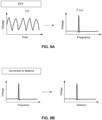
- step S31 the processor 59 converts the waveform signal (voltage versus time) to a frequency spectrum (voltage versus frequency) using the FFT below.
- FIG. 9A is a diagram of conversion of the waveform signal (voltage versus time) to a frequency spectrum (voltage versus frequency).
- N is the number of data points.
- step S32 the processor 59 converts the frequency spectrum (voltage versus frequency) to a distance spectrum (voltage versus distance).
- FIG. 9B is a diagram of conversion of the frequency spectrum (voltage versus frequency) to a distance spectrum (voltage versus distance).
- step S33 the processor 59 calculates the distance value corresponding to a peak based on the distance spectrum (voltage versus distance).
- FIG. 9C is a diagram of peak detection based on distance spectra (voltage versus distance) and calculation of distance values corresponding to the respective peaks.
- peaks are detected in three channels based on the respective spectra (voltage versus distance) to calculate the distance values corresponding to the respective peaks.
- step S34 the processor 59 calculates an average of the distance values calculated in step S33. More specifically, the processor 59 calculates an average of the distance values calculated from the respective peaks detected based on the spectra (voltage versus distance) in the three channels in step S33. The processor 59 outputs the average of the values as the distance to the measurement target T.
- the processor 59 may calculate an average of distance values with a signal-to-noise ratio (SNR) greater than or equal to a threshold selected from the distance values calculated in step S33. For example, among the peaks detected in all of the three channels based on the respective spectra (voltage versus distance), any distance value calculated based on a spectrum with a SNR less than the threshold is determined to be less reliable and is not used.
- SNR signal-to-noise ratio
- An optical interferometric range sensor described below corresponds to the displacement sensor 10 described with reference to FIGs. 1 to 9C . All or some of the basic components, functions, and characteristics of the optical interferometric range sensor are the same as the components, functions, and characteristics of the displacement sensor 10 described with reference to FIGs. 1 to 9C .
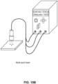
- FIGs. 10A and 10B are each a schematic external view of an optical interferometric range sensor according to one embodiment of the present invention used in a different form.
- the optical interferometric range sensor shown in FIG. 10A measures the distances to measurement targets using three single spot heads.
- the optical interferometric range sensor shown in FIG. 10B measures the distance to a measurement target using a single multi-spot head for three spots.
- the number of spots is three, but not limited to this.
- two or four or more single spot heads may be used, or a single multi-spot head for two or four or more spots may be used.
- Appropriate measurement conditions are to be set based on whether the optical interferometric range sensor includes multiple single spot heads or a single multi-spot head. Adjusting, for example, the amount of light as appropriate for the type of sensor head will be described in detail later.
- FIG. 11 is a schematic diagram of an optical interferometric range sensor 100 according to one embodiment of the present invention.
- the optical interferometric range sensor 100 includes a wavelength swept light source 110, a light splitter 120, an interferometer 130, light receivers 140a to 140c, a processor 150, an identifier 160, and a light adjuster 170.
- the wavelength swept light source 110, the light splitter 120, the light receivers 140a to 140c, and the processor 150 are included in a controller 101.
- the identifier 160 may be a function implemented by the processor 150 or by, for example, a separate controller.
- the wavelength swept light source 110 is directly connected to the light splitter 120 or indirectly connected to the light splitter 120 with other components (e.g., the optical amplifier 52, the isolator 53, and the optical coupler 54).
- the wavelength swept light source 110 emits light with continuously changing wavelengths. In other words, the wavelength of the light emitted from the wavelength swept light source 110 changes continuously.
- the light emitted from the wavelength swept light source 110 is transmitted to the interferometer 130 through the light splitter 120 and optical fibers.
- the light splitter 120 includes, for example, optical couplers or circulators.
- the light splitter 120 splits light emitted from the wavelength swept light source 110, transmits the split light to the interferometer 130 to be incident on multiple spots, and guides returning light from the interferometer 130 to the light receivers 140a to 140c.
- the light splitter 120 includes optical couplers 120a to 120c in three stages connected in series with one another to split transmitted light toward optical paths A to C to be incident on three spots.
- the light splitter 120 may include the optical couplers 120a to 120c each being, for example, a 2 ⁇ 2 optical coupler.
- Such a light splitter 120 may include an attenuator 122 to attenuate light spilt to another path from the optical coupler 120c in the subsequent stage to reduce returning light to the optical coupler 120c.
- the interferometer 130 includes the three single spot heads shown in FIG. 10A or the single multi-spot head (three spots) shown in FIG. 10B as a sensor head.
- the sensor head includes lenses 130a to 130c in this specific example, the sensor head may include collimating lenses or an objective lens, or may include both of these lenses.
- a portion of light transmitted through the optical path A reaches the measurement target T through the lens 130a included in the sensor head and is reflected from the measurement target T as measurement light.
- the measurement light reflected from the measurement target T then returns to the optical path A through the lens 130a included in the sensor head.
- Another portion of the light transmitted through the optical path A is reflected from the reference surface at the end of the optical fiber as reference light.
- the measurement light and the reference light interfere with each other to form interference light corresponding to the length difference between the optical path for the measurement light and the optical path for the reference light.
- the interference light is output from the interferometer 130.
- a portion of light transmitted through the optical path B reaches the measurement target T through the lens 130b included in the sensor head and is reflected from the measurement target T as measurement light
- a portion of light transmitted through the optical path C reaches the measurement target T through the lens 130c included in the sensor head and is reflected from the measurement target T as measurement light.
- the measurement light reflected from the measurement target T then returns to the optical path B through the lens 130b included in the sensor head, and to the optical path C through the lens 130c included in the sensor head.
- Another portion of the light transmitted through the optical paths B is reflected from the reference surface at the end of the optical fiber as reference light.
- Another portion of the light transmitted through the optical paths C is reflected from the reference surface at the end of the optical fiber as reference light.
- the measurement light and the reference light interfere with each other to form interference light corresponding to the length difference between the optical path for the measurement light and the optical path for the reference light.
- the interference light is output from the interferometer 130.
- the interference light corresponding to each of the optical paths A to C output from the interferometer 130 is received by each of the light receivers 140a to 140c through the light splitter 120 (optical couplers 120a to 120c) and converted to electric signals.
- the light receiver 140a includes a light receiving element 141a and an AD converter 142a
- the light receiver 140b includes a light receiving element 141b and an AD converter 142b
- the light receiver 140c includes a light receiving element 141c and an AD converter 142c.
- the light receiving elements 141a to 141c are, for example, photodetectors, and receive light output from the light splitter 120 (optical couplers 120a to 120c) and convert the light to electric signals each corresponding to the received amount of light.
- the AD converters 142a to 142c convert the electric signals from analog signals to digital signals.
- the processor 150 calculates the distance from the sensor head to the measurement target T based on the digital signals resulting from conversion performed by the light receivers 140a to 140c.
- the processor 150 includes an integrated circuit such as an FPGA.
- the processor 150 converts each input digital signal to a frequency spectrum using an FFT and calculates the distance to the measurement target T based on the frequency spectra.
- the distance from the sensor head to the measurement target T is typically, but not limited to, the distance from the distal end of the sensor head to the measurement target T.
- the processor 150 calculates this distance. For example, the processor 150 may calculate, as the distance from the sensor head to the measurement target T, the distance from the end of the optical fiber connected to the sensor head to the measurement target T, the distance from the objective lens in the sensor head to the measurement target T, or the distance from a reference position preset within the sensor head to the measurement target T.
- FIGs. 12A and 12B are each a schematic diagram of a sensor head used in the optical interferometric range sensor 100 according to one embodiment of the present invention.
- FIG. 12A three single spot heads 131a are used for the optical paths A to C.
- FIG. 12B a single multi-spot head 131b for three spots is used for the optical paths A to C.
- the optical interferometric range sensor 100 includes either type of sensor head.
- the identifier 160 identifies the type of sensor head based on a beat signal generated by the interferometer 130. For example, the identifier 160 identifies, based on a beat signal generated by the interferometer 130, the single spot heads 131a shown in FIG. 12A or the multi-spot head 131b shown in FIG. 12B as the sensor head being used in the optical interferometric range sensor 100.
- the beat signal generated by the interferometer 130 is generated by optical signals traveling on different optical path lengths interfering with each other, which will be described in specific examples together with the identification method described later.
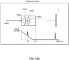
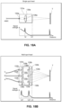
- FIGs. 13A and 13B are each a schematic diagram of a sensor head to be identified as a single spot head 131a or a multi-spot head 131b in one specific example.
- a portion of the light input into the single spot head 131a through the optical fiber reaches the measurement target T as measurement light and is reflected from the measurement target T.
- Another portion of the light input into the single spot head 131a is reflected from a reference surface 133a at the end of the optical fiber as reference light.
- the measurement light and the reference light form interference light, allowing detection of the distance from the single spot head 131a to the measurement target T as a signal peak.
- Still another portion of the light input into the single spot head 131a through the optical fiber is reflected from a reflective surface 134a on the objective lens 132a.
- the reflected light and the reference light described above form a beat signal (interference light), allowing detection of a position Lp of the objective lens 132a (specifically, the reflective surface 134a) in the single spot head 131a (specifically, in the area from a distal end position LH of the sensor head 131a toward the reference surface 133a) as a signal peak.
- the reflective surface 134a on the objective lens 132a may be on either surface of the objective lens 132a.
- the reflective surface 134a may be a partial reflective coating applied to the objective lens 132a, or may be a portion using Fresnel reflection with, for example, low reflectance (about 5% or less).
- the objective lens 132b in the multi-spot head 131b (specifically, in the area from a distal end position LH of the sensor head 131b toward reference surfaces 133b) includes reflective surfaces 134b to reflect a portion of the light input into the multi-spot head 131b through the optical fibers.
- the reflected light and the reference light described above form a beat signal (interference light), allowing detection of a position Lp of the objective lens 132b (specifically, the reflective surfaces 134b) in the multi-spot head 131b as a signal peak.
- a beat signal is generated by the interferometer 130 including the single spot heads 131a or the multi-spot head 131b.
- the beat signal is received by the light receivers 140a to 140c, allowing detection of the signal peak as shown in FIGs. 13A and 13B .
- the identifier 160 can identify the type of sensor head based on the peak of the beat signal with, for example, the objective lens 132a and the objective lens 132b at different positions respectively in the single spot head 131a shown in FIG. 13A and the multi-spot head 131b shown in FIG. 13B .
- one single spot head 131a is described as an example. However, as shown in FIG. 12A , with three similar single spot heads 131a being used, a similar position Lp is detected based on the beat signal received by each of the light receivers 140a to 140c.
- the objective lens 132b includes the reflective surfaces 134b to cause a beat signal to be generated for each of the optical paths A to C in a single multi-spot head 131b. This allows a similar position Lp to be detected based on the beat signal received by each of the light receivers 140a to 140c, but the structure is not limited to this example.
- the objective lens 132b may include the reflective surfaces 134b to cause a beat signal to be generated for one of the optical paths A to C, allowing a position Lp to be detected based on the beat signal received by one of the light receivers 140a to 140c.
- the light adjuster 170 adjusts the amount of light emitted from the sensor head to a measurement target T based on the type of sensor head identified by the identifier 160.
- the light adjuster 170 may control the wavelength swept light source 110 to adjust the amount of light emitted from the wavelength swept light source 110, or may adjust the amount of light emitted from the wavelength swept light source 110 with an amplifier, an attenuator, or both.
- the light adjuster 170 adjusts the amount of light incident on each of the multiple spots in the predetermined area to satisfy the safety standards for laser beams. More specifically, the amount of a laser beam incident on a single spot is to be smaller.
- the light adjuster 170 adjusts the amount of light emitted from each single spot head to allow measurement with high accuracy. More specifically, the amount of a laser beam incident on a single spot is to be larger.
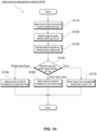
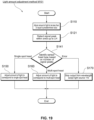
- FIG. 14 is a flowchart showing a light amount adjustment method M100 including identifying the type of sensor head and adjusting the amount of light to correspond to the identified type of sensor head.
- the light amount adjustment method M100 includes steps S110 to S170. Each step is performed by the processor included in the optical interferometric range sensor 100.
- the light adjuster 170 adjusts the amount of light incident on a measurement target T. For example, when the identifier 160 is identifying the type of sensor head, the type of sensor head remains unknown. Thus, the light adjuster 170 adjusts the amount of light to satisfy the safety standards for laser beams. More specifically, the light adjuster 170 sets the amount of light to the amount for the sensor head identified to be a multi-spot head by the identifier 160, for a situation in which a multi-spot head irradiates, with laser beams, multiple spots adjacent to each other in a predetermined area.
- the light adjuster 170 adjusts the amount of light incident on each of the multiple spots to be smaller.
- measurement targets T are irradiated with small amounts of light, thus satisfying the safety standards for laser beams sufficiently.
- the distance to a measurement target T is not measured in this step. Thus, any decrease in the measurement accuracy due to the small amounts of light is not discussed.
- step S120 the identifier 160 detects any signal peak based on the interference light received by the light receivers 140a to 140c within the area up to the distal end position LH of the sensor head. Each signal peak is detected based on the interference light received by each of the light receivers 140a to 140c.
- step S130 the identifier 160 calculates a distance Lp corresponding to each signal peak detected in step S120.
- step S140 the identifier 160 identifies the sensor head as a sensor head including the single spot head 131a or the multi-spot head 131b based on the distance (position) Lp calculated in step S130.
- the distance Lp calculated in step S130 is determined to be closer to (corresponds to) the distance L1 or the distance L2 with comparison of
- the identifier 160 When determining that the distance Lp corresponds to the distance L1 in step S140 (single spot head in step S140), the identifier 160 identifies the single spot head 131a as the sensor head being used.
- the light adjuster 170 adjusts the amount of light to correspond to the single spot head 131a in step S150.
- the identifier 160 When determining that the distance Lp corresponds to the distance L2 in step S140 (multi-spot head in step S140), the identifier 160 identifies the multi-spot head 131b as the sensor head being used.
- the light adjuster 170 adjusts the amount of light to correspond to the multi-spot head 131b in step S160.
- the identifier 160 When determining that the distance Lp corresponds to none of the distances L1 and L2 in step S140 (error in step S140), the identifier 160 cannot identify the type of sensor head. The identifier 160 outputs an error, and the light adjuster 170 causes the wavelength swept light source 110 to stop outputting light in step S170.
- the error include the distance Lp, which is calculated in step S130 for each signal peak detected based on the interference light received by each of the light receivers 140a to 140c in step S 120, being out of a range determined to correspond to the distance L1 or L2, and the distance Lp corresponding to both the distances L1 and L2.
- a sensor head different from an expected sensor head may possibly be connected, both a single spot head and a multi-spot head may possibly be connected, or no sensor head may possibly be connected.
- the identifier 160 thus cannot identify the type of sensor head (error).
- the light adjuster 170 may cause the wavelength swept light source 110 to stop outputting light and may also output an error message corresponding to the error estimated based on the calculated distance Lp.
- the light amount adjustment method M100 may be performed upon setting measurement conditions for measurement of the measurement target T, or for example, before start of the measurement or upon each measurement of the measurement target T.
- the optical interferometric range sensor 100 includes the identifier 160 that identifies the type of sensor head as the single spot head or the multi-spot head based on the beat signal generated by the interferometer 130.
- the light adjuster 170 adjusts the amount of light to correspond to the type of sensor head identified by the identifier 160. This allows the amount of light to be adjusted as appropriate for the sensor head, thus allowing the measurement distance to the measurement target T to be measured with high accuracy while satisfying the safety standards for laser beam irradiation. This reduces the user work of, for example, identifying the type of sensor head and manually setting the corresponding amount of light in each measurement operation.
- the single spot head 131a described with reference to FIG. 13A includes a collimating lens between the end of the optical fiber and the objective lens 132a
- the multi-spot 131b described with reference to FIG. 13B includes collimating lenses between the ends of the optical fibers and the objective lens 132b.
- This structure collimates light incident on the objective lens 132a or 132b, thus allowing more flexibility in the position of the reflective surface 134a on the objective lens 132a or the positions of the reflective surfaces 134b on the objective lens 132b.
- the single spot head 131a and the multi-spot head 131b may have any structures, other than those shown in FIGs. 13A and 13B , that can identify the type of sensor head based on the beat signal generated by the interferometer 130. Such structures that allow identification of the type of sensor head will now be described.
- FIGs. 15A and 15B are each a schematic diagram of a sensor head including one or more collimating lenses to be identified as the single spot head 131a or the multi-spot head 131b in one specific example.
- the single spot head 131a includes a collimating lens 135a without an objective lens
- the multi-spot head 131b includes collimating lenses 135b without an objective lens.
- the collimating lens 135a includes a reflective surface 136a to reflect a portion of the light input into the single spot head 131a through the optical fiber.
- the collimating lenses 135b each include a reflective surface 136b to reflect a portion of the light input into the multi-spot head 131b through the optical fibers.
- the collimating lens 135a and the collimating lenses 135b are at different positions in the respective single spot head 131a and multi-spot head 131b to allow the identifier 160 to identify the type of sensor head based on the peak of the beat signal.
- the single spot head 131a and the multi-spot head 131b described with reference to FIGs. 15A and 15B each have a simple structure without an objective lens, thus facilitating detection of the peak of the beat signal.
- FIGs. 16A and 16B are each a schematic diagram of a sensor head including an internal component with one or more reflective surfaces to be identified as the single spot head 131a or the multi-spot head 131b in one specific example.
- the single spot head 131a includes a predetermined component 137a inside the housing
- the multi-spot head 131b includes predetermined components 137b inside the housing.
- the predetermined component 137a reflects, within the housing of the single spot head 131a, a portion of the light input into the single spot head 131a through the optical fiber.
- the predetermined components 137b reflect, within the housing of the multi-spot head 131b, a portion of the light input into the multi-spot head 131b through the optical fibers.
- the predetermined component 137a and the predetermined components 137b are at different positions in the respective single spot head 131a and multi-spot head 131b to allow the identifier 160 to identify the type of sensor head based on the peak of the beat signal.
- the single spot head 131a and the multi-spot head 131b described with reference to FIGs. 16A and 16B each eliminate a reflective surface located on a collimating lens or an objective lens, facilitating detection of the peak of the beat signal with the predetermined component 137a or the predetermined components 137b positioned to reflect a portion of the light input into the single spot head 131a or the multi-spot head 131b.
- the predetermined components 137a and 137b may each be a portion of a component of the single spot head 131a or the multi-spot head 131b, or may be a separate component for generating the peak of the beat signal.
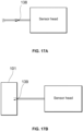
- FIG. 17A is a schematic diagram of an optical fiber including a reflective surface to allow identification of the type of sensor head in one specific example.
- a reflective surface 138 is located inside the optical fiber that guides light to the sensor head, instead of inside the sensor head. More specifically, the reflective surface 138 may be a partial reflective coating applied to a joint of optical fibers.
- an optical fiber connected to a single spot head 131a and an optical fiber connected to a multi-spot head 131b may include reflective surfaces 138 at different positions. This allows the identifier 160 to identify the type of sensor head based on the peak of the beat signal.
- the end (end face) of the optical fiber is used as the position at which the optical path difference is zero.
- the peak of the beat signal thus occurs, along the return path, in an area toward the distal end of the sensor head from the position at which the optical path difference is zero.
- FIG. 17B is a schematic diagram of an optical fiber including a reflective surface at an end (end face) adjacent to a controller 101 to allow identification of the type of sensor head in one specific example.
- a reflective surface 139 is located at, instead of inside the sensor head, the end (end face) of the optical fiber adjacent to the controller 101 that guides light to the sensor head. More specifically, the reflective surface 139 may be a partial reflective coating applied to the end (end face) of the optical fiber adjacent to the controller 101.
- the end (end face) of the optical fiber is used as the position at which the optical path difference is zero.
- the peak of the beat signal thus occurs, along the return path, in an area toward the distal end of the sensor head offset from the position at which the optical path difference is zero by the optical path length difference.
- an optical fiber connected to a single spot head 131a and an optical fiber connected to a multi-spot head 131b may be designed to have different lengths (optical path length) to allow the identifier 160 to identify the type of sensor head based on the peak of the beat signal.
- one or more reflective surfaces are located inside the sensor head including one or more collimating lenses, the objective lens, and other components, or located inside or on an end face of the optical fiber to generate a beat signal in the interferometer 130.
- a single spot head 131a and a multi-spot head 131b may be designed to allow detection of different peaks in the beat signals to allow the identifier 160 to identify the type of sensor head based on the peak of the beat signal.
- the structures described with reference to FIGs. 13A and 13B and 15A to 17B may be combined.
- the predetermined component 137a is placed inside the single spot head 131a ( FIG. 16A ).
- the reflective surface 138 is located inside the optical fiber ( FIG. 17A ).
- FIGs. 18A and 18B are each a schematic diagram of a sensor head to be identified as the single spot head 131a or the multi-spot head 131b based on the number of peaks in a beat signal in one specific example. As shown in FIGs. 18A and 18B , the single spot head 131a and the multi-spot head 131b have different structures. The type of sensor head is identified based on the number of peaks, instead of the frequency (position and distance) at the peak of the beat signal generated by the interferometer 130.
- the single spot head 131a includes a collimating lens 135a without including an objective lens.
- a portion of the light input into the single spot head 131a through the optical fiber is reflected from a reflective surface 136a on the collimating lens 135a.
- the reflected light then forms a beat signal (interference light) with the reference light reflected from a reference surface 133a at the end of the optical fiber.
- This allows detection of a position Lp of the collimating lens 135a (specifically, the reflective surface 136a) as a signal peak within the sensor head 131a (specifically, in the area from a distal end position LH of the single spot head 131a toward the reference surface 133a).
- the multi-spot head 131b includes collimating lenses 135b and an objective lens 132b.
- a portion of the light input into the multi-spot head 131b through the optical fibers is reflected from reflective surfaces 136b on the collimating lenses 135b and reflective surfaces 134b on the objective lens 132b.
- Each of the light reflected from the reflective surfaces 136b and the light reflected from the reflective surfaces 134b forms a beat signal (interference light) with the reference light reflected from reference surfaces 133b at the ends of the optical fibers.
- the single spot head 131a includes the collimating lens 135a
- the multi-spot head 131b includes the collimating lenses 135b and the objective lens 132b.
- the identifier 160 can identify the type of sensor head based on the number of peaks detected in the beat signal.
- FIG. 19 is a flowchart showing a light adjustment method M101 including identifying the type of sensor head based on the number of peaks detected in the beat signal and adjusting the amount of light to correspond to the identified type of sensor head.
- the light adjustment method M101 includes steps S110, S121, S141, and S150 to S170. Each step is performed by the processor included in the optical interferometric range sensor 100.
- the light adjuster 170 adjusts the amount of light incident on a measurement target T. For example, the light adjuster 170 adjusts the amount of light to satisfy the safety standards for laser beams for a situation in which a multi-spot head irradiates, with laser beams, multiple spots adjacent to each other in a predetermined area.
- the identifier 160 detects any signal peak based on the interference light received by the light receivers 140a to 140c within the area up to the distal end position LH of the sensor head. For example, the identifier 160 may detect any signal peak having a signal strength of a predetermined value or greater.
- step S141 the identifier 160 identifies the sensor head as a sensor head including the single spot head 131a or the multi-spot head 131b based on the number of signal peaks detected in step S121.
- the collimating lens 135a is pre-positioned to cause one signal peak (as in, for example, FIG. 18A ).
- the collimating lenses 135b and the objective lens 132b are pre-positioned to cause two signal peaks (as in, for example, FIG. 18B ).
- the determination may be performed as to whether the number of signal peaks detected in step S121 is one or two.
- the identifier 160 When determining that the number of signal peaks is one in step S141 (single spot head in step S141), the identifier 160 identifies the single spot head 131a as the sensor head being used. The light adjuster 170 adjusts the amount of light to correspond to the single spot head 131a in step S150.
- the identifier 160 When determining that the number of signal peaks is two in step S141 (multi-spot head in step S141), the identifier 160 identifies the multi-spot head 131b as the sensor head being used.
- the light adjuster 170 adjusts the amount of light to correspond to the multi-spot head 131b in step S160.
- the identifier 160 When determining that the number of signal peaks corresponds to none of one and two in step S141 (error in step S141), the identifier 160 cannot identify the type of sensor head. The identifier 160 outputs an error, and the light adjuster 170 causes the wavelength swept light source 110 to stop outputting light in step S170.
- the error include no signal peaks with a signal strength greater than or equal to a predetermined value being detected based on the interference light received by the light receivers 140a to 140c in step S121, and three or more signal peaks being detected.
- a sensor head different from an expected sensor head may possibly be connected, both a single spot head and a multi-spot head may possibly be connected, or no sensor head may possibly be connected.
- the identifier 160 thus cannot identify the type of sensor head (error).
- the light adjuster 170 may cause the wavelength swept light source 110 to stop outputting light and may also output an error message corresponding to the error estimated based on the detected number of signal peaks.
- the optical interferometric range sensor 100 includes the interferometer 130 being a Fizeau interferometer that generates reference light using the end of the optical fiber as a reference surface.
- the interferometer is not limited to the Fizeau interferometer.
- FIGs. 20A, 20B , and 20C are diagrams of interferometers that generate interference light using measurement light and reference light in modifications.
- a light splitter 121 splits light on each of optical paths A to C into reference light that uses the end of the optical fiber as a reference surface and measurement light emitted from the sensor head and then reaching and reflected from a measurement target T. Interference light occurs based on the difference in optical path lengths between the reference light and the measurement light.
- This structure includes the same interferometer as the interferometer 130 (Fizeau interferometer) in the optical interferometric range sensor 100 according to the embodiments described above.
- the reference surface may reflect light due to the difference in refractive index between the optical fiber and air (Fresnel reflection).
- the end of the optical fiber may be coated with a reflective film, or may be coated with a non-reflective film and receive a reflective surface such as a lens surface separately.
- the light splitter 121 splits light on the optical paths A to C into measurement light to be guided along measurement paths Lm1 to Lm3 to the measurement target T and reference light to be guided along reference optical paths Lr1 to Lr3.
- the reference optical paths Lr1 to Lr3 each include a reference surface at its end (Michelson interferometer).
- the reference surface may be an end of an optical fiber coated with a reflective film, or may be an end of an optical fiber coated with a non-reflective film and receiving, for example, a mirror separately.
- This structure generates interference light on the optical path A with the length difference between the measurement optical path Lm1 and the reference optical path Lr1, interference light on the optical path B with the length difference between the measurement optical path Lm2 and the reference optical path Lr2, and interference light on the optical path C with the length difference between the measurement optical path Lm3 and the reference optical path Lr3.
- the light splitter 121 splits light on the optical paths A to C into measurement light to be guided along measurement optical paths Lm1 to Lm3 to the measurement target T and reference light to be guided along reference optical paths Lr1 to Lr3.
- the reference optical paths Lr1 to L3 each include a balance detector (Mach-Zehnder interferometer). This structure generates interference light on the optical path A with the length difference between the measurement optical path Lm1 and the reference optical path Lr1, interference light on the optical path B with the length difference between the measurement optical path Lm2 and the reference optical path Lr2, and interference light on the optical path C with the length difference between the measurement optical path Lm3 and the reference optical path Lr3.
- the interferometer is not limited to the Fizeau interferometer described in the embodiment, and may be, for example, a Michelson or Mach-Zehnder interferometer, or any other interferometer that can generate interference light by setting the optical path length difference between the measurement light and the reference light. These or other interferometers may be combined.
- An optical interferometric range sensor comprising:
Landscapes
- Physics & Mathematics (AREA)
- General Physics & Mathematics (AREA)
- Engineering & Computer Science (AREA)
- Signal Processing (AREA)
- Remote Sensing (AREA)
- Radar, Positioning & Navigation (AREA)
- Computer Networks & Wireless Communication (AREA)
- Mathematical Physics (AREA)
- Optics & Photonics (AREA)
- Electromagnetism (AREA)
- Automation & Control Theory (AREA)
- Length Measuring Devices By Optical Means (AREA)
- Instruments For Measurement Of Length By Optical Means (AREA)
Abstract

Description
- This application claims priority to
Japanese Patent Application No. 2022-038245 filed on March 11, 2022 - The present invention relates to an optical interferometric range sensor.
- Nowadays, optical range sensors are commonly used to contactlessly measure the distance to a measurement target. For example, a known optical range sensor includes an optical interferometric range sensor that generates, from light emitted from a wavelength swept light source, interference light based on reference light and measurement light and measures the distance to a measurement target based on the interference light.
- Another known optical interferometric range sensor irradiates a measurement target with multiple beams and measures the measurement target with high accuracy.
-
Patent Literature 1 describes an optical measurement device that causes a returning beam component of a reference beam reflected from the end faces of multiple optical fibers to coherently interfere with a reflected component of a measurement beam reflected from a surface of a measurement target to obtain stable measurement results. - Patent Literature 1:
Japanese Patent No. 2686124 - The known optical interferometric range sensor irradiating a measurement target with multiple beams may include multiple single spot heads each emitting a single beam or including a single multi-spot head that emits multiple beams.
- The use of the multi-spot head may place a user in an insecure situation when multiple laser beams are emitted to a predetermined area. For example, safety based on safety standards for laser beams may be compromised. Although the amount of laser beams to be emitted may be reduced to increase safety, the use of multiple single spot heads located at predetermined intervals may lower the measurement accuracy due to the small amount of laser beams being emitted.
- One or more aspects of the present invention are directed to an optical interferometric range sensor that can adjust the amount of light as appropriate for a sensor head.
- An optical interferometric range sensor according to one aspect of the present invention includes a light source that emits light with a changing wavelength, a light splitter that splits the light emitted from the light source into a plurality of beams to be incident on a plurality of spots, an interferometer that generates, for each of the plurality of beams of the split light incident on a corresponding spot of the plurality of spots, interference light based on measurement light emitted from a sensor head to a measurement target and reflected from the measurement target and reference light traveling on an optical path at least partially different from an optical path of the measurement light, a light receiver that receives the interference light from the interferometer to convert the interference light to an electric signal, a processor that calculates a distance from the sensor head to the measurement target based on the electric signal resulting from conversion performed by the light receiver, an identifier that identifies the sensor head based on a beat signal generated by the interferometer, and a light adjuster that adjusts an amount of light to be emitted from the sensor head to the measurement target based on the sensor head identified by the identifier.
- In this aspect, the identifier identifies the sensor head based on the beat signal generated by the interferometer, and the light adjuster adjusts, based on the sensor head identified by the identifier, the amount of light emitted from the sensor head to the measurement target. This allows the amount of light incident on the measurement target to be adjusted as appropriate for the sensor head, thus allowing the measurement distance from the sensor head to the measurement target to be measured with high accuracy while satisfying the safety standards for laser beam irradiation. This reduces the user work of, for example, identifying the type of sensor head and manually setting the corresponding amount of light in each measurement operation.
- In the above aspect, the sensor head may include a single spot head or a multi-spot head.
- In this aspect, the optical interferometric range sensor can identify the sensor head being used as multiple single spot heads or a single multi-spot head for multiple spots and adjust the amount of light as appropriate for each head.
- In the above aspect, the light adjuster may adjust an amount of light to be transmitted to the light splitter to be less than or equal to a predetermined value when the identifier identifies the sensor head.
- In this aspect, when the sensor head is unidentified, the light adjuster adjusts the amount of light to less than or equal to the predetermined value to satisfy the safety standards for laser beams.
- In the above aspect, the predetermined value may be an amount of light adjusted for the sensor head identified as a multi-spot head by the identifier.
- In this aspect, when the sensor head is unidentified, the light adjuster adjusts the amount of light to the amount for a sensor head being a multi-spot head. The safety standards for laser beams can be sufficiently satisfied for the sensor head that may be a multi-spot head.
- In the above aspect, the identifier may identify the sensor head based on at least one of a peak frequency of the beat signal or the number of peaks in the beat signal.
- In this aspect, the identifier identifies the sensor head based on at least one of the peak frequency of the beat signal or the number of peaks in the beat signal, thus facilitating identification of the sensor head without causing the user to determine the type of sensor head.
- In the above aspect, the beat signal may result from a portion of the light emitted from the light source and received by the interferometer being reflected from a component of the interferometer including a reflective surface.
- In this aspect, the beat signal results from a portion of the light emitted from the light source and received by the interferometer being reflected from the component of the interferometer including the reflective surface, thus facilitating identification of the sensor head without causing the user to determine the type of sensor head.
- In the above aspect, the reflective surface may be located inside the sensor head.
- In this aspect, the reflective surface is located inside the sensor head. This reduces the user work including determination and preparation associated with the sensor head, other than attaching the sensor head, thus facilitating identification of the sensor head.
- In the above aspect, the reflective surface may be located on an objective lens included in the sensor head.
- In this aspect, the reflective surface is located on the objective lens included in the sensor head, thus eliminating preparation of, for example, a separate component and facilitating identification of the sensor head.
- In the above aspect, the reflective surface may be located on a collimating lens included in the sensor head.
- In this aspect, the reflective surface is located on the collimating lens included in the sensor head, thus eliminating preparation of, for example, a separate component and facilitating identification of the sensor head.
- In the above aspect, the reflective surface may be located inside an optical fiber that guides the light emitted from the light source to the sensor head.
- In this aspect, the reflective surface is located inside the optical fiber that guides light emitted from the light source to the sensor head, thus facilitating identification of the sensor head without a reflective surface in the sensor head.
- The optical interferometric range sensor according to the above aspects of the present invention can adjust the amount of light as appropriate for the sensor head.
-
-
FIG. 1 is a schematic external view of adisplacement sensor 10 according to an embodiment of the present disclosure. -
FIG. 2 is a flowchart showing measurement of a measurement target T with thedisplacement sensor 10 according to the embodiment of the present disclosure. -
FIG. 3 is a functional block diagram of asensor system 1 including thedisplacement sensor 10 according to the embodiment of the present disclosure. -
FIG. 4 is a flowchart showing measurement of the measurement target T with thesensor system 1 including thedisplacement sensor 10 according to the embodiment of the present disclosure. -
FIG. 5A is a diagram describing a basic measurement procedure of the measurement target T with thedisplacement sensor 10 according to the embodiment of the present disclosure. -
FIG. 5B is a diagram describing another basic measurement procedure of the measurement target T with thedisplacement sensor 10 according to the embodiment of the present disclosure. -
FIG. 6A is a schematic perspective view of asensor head 20. -
FIG. 6B is a schematic view of thesensor head 20 showing the internal structure. -
FIG. 7 is a block diagram of acontroller 30 showing signal processing in thecontroller 30. -
FIG. 8 is a flowchart showing a method for calculating the distance to the measurement target T with aprocessor 59 in thecontroller 30. -
FIG. 9A is a diagram of conversion of a waveform signal (voltage versus time) to a frequency spectrum (voltage versus frequency). -
FIG. 9B is a diagram of conversion of the frequency spectrum (voltage versus frequency) to a distance spectrum (voltage versus distance). -
FIG. 9C is a diagram of peak detection based on distance spectra (voltage versus distance) and calculation of distance values corresponding to the respective peaks. -
FIGs. 10A and10B are each a schematic external view of an optical interferometric range sensor according to one embodiment of the present invention used in a different form. -
FIG. 11 is a schematic diagram of an opticalinterferometric range sensor 100 according to one embodiment of the present invention. -
FIGs. 12A and 12B are each a schematic diagram of asensor head 100 used in the opticalinterferometric range sensor 100 according to the embodiment of the present invention. -
FIGs. 13A and13B are each a schematic diagram of a sensor head to be identified as asingle spot head 131a or amulti-spot head 131b in one specific example. -
FIG. 14 is a flowchart showing a light amount adjustment method M100 including identifying the type of sensor head and adjusting the amount of light to correspond to the identified type of sensor head. -
FIGs. 15A and 15B are each a schematic diagram of a sensor head including one or more collimating lenses to be identified as thesingle spot head 131a or themulti-spot head 131b in one specific example. -
FIGs. 16A and 16B are each a schematic diagram of a sensor head including an internal component with one or more reflective surfaces to be identified as thesingle spot head 131a or themulti-spot head 131b in one specific example. -
FIG. 17A is a schematic diagram of an optical fiber including a reflective surface to allow identification of the type of sensor head in one specific example. -
FIG. 17B is a schematic diagram of an optical fiber including a reflective surface at an end (end face) adjacent to acontroller 101 to allow identification of the type of sensor head in one specific example. -
FIGs. 18A and 18B are each a schematic diagram of a sensor head to be identified as thesingle spot head 131a or themulti-spot head 131b based on the number of peaks in a beat signal in one specific example. -
FIG. 19 is a flowchart showing a light adjustment method M101 including identifying the type of sensor head based on the number of peaks detected in the beat signal and adjusting the amount of light to correspond to the identified type of sensor head. -
FIGs. 20A, 20B , and20C are diagrams of interferometers that generate interference light using measurement light and reference light in modifications. - Embodiments of the present invention will now be described specifically with reference to the accompanying drawings. The embodiments described below are merely illustrative for implementing the present invention and are not to be construed as limiting the invention. To facilitate understanding, the same reference numerals denote the same components in the drawings, and such components will not be described repeatedly.
- An overview of a displacement sensor according to an embodiment of the present disclosure will be described first.
-
FIG. 1 is a schematic external view of adisplacement sensor 10 according to the embodiment of the present disclosure. As shown inFIG. 1 , thedisplacement sensor 10 includes asensor head 20 and acontroller 30 to measure the displacement of a measurement target T (distance to the measurement target T). - The
sensor head 20 and thecontroller 30 are connected with anoptical fiber 40. Anobjective lens 21 is attached to thesensor head 20. Thecontroller 30 includes adisplay 31, asetting unit 32, an external interface (I/F) 33, anoptical fiber connector 34, anexternal storage 35, and aninternal measurement processor 36. - The
sensor head 20 irradiates the measurement target T with light output from thecontroller 30 and receives reflected light from the measurement target T. Thesensor head 20 includes a reference surface inside that reflects light output from thecontroller 30 and received through theoptical fiber 40 and causes such light to interfere with the reflected light from the measurement target T described above. - The
objective lens 21 attached to thesensor head 20 is detachable. Theobjective lens 21 is replaceable with another objective lens having a focal length appropriate for the distance between thesensor head 20 and the measurement target T, or is a variable-focus objective lens. - The
sensor head 20, the measurement target T, or both may be positioned to have the measurement target T appropriately being within the measurement area of thedisplacement sensor 10 by irradiating the measurement target T with guide light (visible light). - The
optical fiber 40 is connected to theoptical fiber connector 34 on thecontroller 30 and extends to connect thecontroller 30 and thesensor head 20. Theoptical fiber 40 thus guides light emitted from thecontroller 30 to thesensor head 20 and returning light from thesensor head 20 to thecontroller 30. Theoptical fiber 40 is detachable from thesensor head 20 and thecontroller 30. The optical fiber may have any length, thickness, and characteristics. - The
display 31 is, for example, a liquid crystal display or an organic electroluminescent (EL) display. Thedisplay 31 displays the setting values of thedisplacement sensor 10, the amount of returning light received from thesensor head 20, and measurement results measured by thedisplacement sensor 10, such as the displacement of the measurement target T (distance to the measurement target T). - The setting
unit 32 receives settings associated with measurement of the measurement target T through user operations performed on mechanical buttons or a touchscreen. All or some of the associated settings may be preset or set through an external connection device (not shown) connected to the external I/F 33. The external connection device may be connected with a wire or wirelessly through a network. - The external I/
F 33 includes, for example, Ethernet (registered trademark), Recommended Standard (RS) 232C, and analog output. The external I/F 33 may be connected to an external connection device to allow the associated settings to be input through the external connection device or to output, for example, measurement results measured by thedisplacement sensor 10 to the external connection device. - The
controller 30 may import data stored in theexternal storage 35 to perform the settings associated with measurement of the measurement target T. Theexternal storage 35 is, for example, an auxiliary storage, such as a universal serial bus (USB) memory, which prestores settings associated with measurement of the measurement target T. - The
measurement processor 36 in thecontroller 30 includes, for example, a wavelength swept light source that emits light with continuously changing wavelengths, a light receiving element that receives returning light from thesensor head 20 to convert the received light to an electric signal, and a signal processing circuit that processes the electric signal. Themeasurement processor 36 performs various processes using, for example, a controller and a storage to calculate the displacement of the measurement target T (distance to the measurement target T) based on the returning light from thesensor head 20. These processes will be described in detail later. -
FIG. 2 is a flowchart showing measurement of the measurement target T with thedisplacement sensor 10 according to the embodiment of the present disclosure. As shown inFIG. 2 , this procedure includes steps S11 to S14. - In step S11, the
sensor head 20 is positioned. For example, thesensor head 20 irradiates the measurement target T with guide light, which is used as a reference to position thesensor head 20 appropriately. - More specifically, the
display 31 in thecontroller 30 may display the amount of returning light from thesensor head 20. The user may refer to the amount of returning light to adjust, for example, the orientation of thesensor head 20 and the distance (position in height) from the measurement target T. Typically, when thesensor head 20 irradiates the measurement target T perpendicularly (at angles closer to 90 degrees), more light is reflected from the measurement target T, and more returning light is received from thesensor head 20. - The
objective lens 21 may be replaced with another objective lens having a focal length appropriate for the distance between thesensor head 20 and the measurement target T. - When settings appropriate for measuring the measurement target T are not possible (e.g., the amount of light appropriate for measurement is not received, or the focal length of the
objective lens 21 is inappropriate), a message indicating an error or incomplete settings may be displayed on thedisplay 31 or output to the external connection device for the user. - In step S12, various measurement conditions are set to measure the measurement target T. For example, the user sets unique calibration data (e.g., a function to correct linearity) for the
sensor head 20 by operating thesetting unit 32 in thecontroller 30. - Various parameters may also be set. For example, the sampling time, the measurement area, and the threshold for determining whether the measurement result is normal or abnormal are set. The measurement cycle may also be set based on the characteristics of the measurement target T such as the reflectance and the material of the measurement target T. The measurement mode may be set based on the material of the measurement target T.
- These measurement conditions and various parameters are set by operating the
setting unit 32 in thecontroller 30, but may also be set through an external connection device or by importing data from theexternal storage 35. - In step S13, the
sensor head 20 positioned in step S11 measures the measurement target T in accordance with the measurement conditions and various parameters set in step S12. - More specifically, in the
measurement processor 36 included in thecontroller 30, the wavelength swept light source emits light, the light receiving element receives returning light from thesensor head 20, and the signal processing circuit performs, for example, frequency analysis, distance conversion, and peak detection to calculate the displacement of the measurement target T (distance to the measurement target T). The measurement will be specifically described in detail later. - In step S14, the results of the measurement performed in step S13 are output. For example, the displacement of the measurement target T (distance to the measurement target T) measured in step S13 and other information are displayed on the
display 31 in thecontroller 30 or output to the external connection device. - The measurement result displayed or output may also include whether the displacement of the measurement target T (distance to the measurement target T) measured in step S13 is within a normal range or is abnormal based on the threshold set in step S12. The measurement conditions, the parameters, and the measurement mode set in step S12 may also be displayed or output together.
-
FIG. 3 is a functional block diagram of asensor system 1 including thedisplacement sensor 10 according to the embodiment of the present disclosure. As shown inFIG. 3 , thesensor system 1 includes thedisplacement sensor 10, acontrol device 11, asensor 12 for control signal input, and anexternal connection device 13. Thedisplacement sensor 10 is connected to thecontrol device 11 and theexternal connection device 13 with, for example, a communication cable or an external connection cord (e.g., an external input line, an external output line, or a power line). Thecontrol device 11 and thesensor 12 for control signal input are connected with a signal line. - The
displacement sensor 10 measures the displacement of the measurement target T (distance to the measurement target T) as described with reference toFIGs. 1 and2 . Thedisplacement sensor 10 may then output the measurement results and other information to thecontrol device 11 and theexternal connection device 13. - The
control device 11 is, for example, a programmable logic controller (PLC), which provides various instructions to thedisplacement sensor 10 measuring the measurement target T. - For example, the
control device 11 may output a measurement time signal to thedisplacement sensor 10 based on an input signal from thesensor 12 for control signal input connected to thecontrol device 11 or may output, for example, a zero reset command signal (a signal to set the current measurement value to zero) to thedisplacement sensor 10. - The
sensor 12 for control signal input outputs an on-signal or an off-signal to thecontrol device 11 to indicate the time for thedisplacement sensor 10 to measure the measurement target T. For example, thesensor 12 for control signal input is installed near the production line carrying the measurement target T to output the on- or off-signal to thecontrol device 11 upon detecting the measurement target T moved to a predetermined position. - The
external connection device 13 is, for example, a personal computer (PC), which is operable by the user to perform various settings with thedisplacement sensor 10. - In an example, a measurement mode, an operation mode, a measurement cycle, and the material of the measurement target T are set.
- The measurement mode is selectively set to, for example, an internal synchronous measurement mode in which measurement starts periodically in the
control device 11 or to an external synchronous measurement mode in which measurement starts in response to an input signal from outside thecontrol device 11. - The operation mode is selectively set to, for example, an in-operation mode in which the measurement target T is actually measured or to an adjustment mode in which the measurement conditions are set for measuring the measurement target T.
- The measurement cycle for measuring the measurement target T is set based on the reflectance of the measurement target T. For any measurement target T with low reflectance, a longer measurement cycle may be set as appropriate to allow appropriate measurement of the measurement target T.
- For example, a rough surface mode is selected for a measurement target T reflecting light containing a relatively large amount of diffuse reflection component. A specular surface mode is selected for a measurement target T reflecting light containing a relatively large amount of specular reflection component. A standard mode is selected for a measurement target T reflecting light containing about a half diffuse reflection component and a half specular reflection component.
- Appropriate mode setting based on the reflectance and the material of the measurement target T allows more accurate measurement of the measurement target T.
-
FIG. 4 is a flowchart showing measurement of the measurement target T with thesensor system 1 including thedisplacement sensor 10 according to the embodiment of the present disclosure. As shown inFIG. 4 , this procedure is performed in the external synchronous measurement mode and includes steps S21 to S24. - In step S21, the
sensor system 1 detects a measurement target T, which is an object to be measured. More specifically, thesensor 12 for control signal input detects the measurement target T moved to a predetermined position on the production line. - In step S22, the
sensor system 1 instructs thedisplacement sensor 10 to measure the measurement target T detected in step S21. More specifically, thesensor 12 for control signal input outputs an on-signal or an off-signal to thecontrol device 11 to indicate the time to measure the measurement target T detected in step S21. Thecontrol device 11 outputs a measurement time signal to thedisplacement sensor 10 in response to the on- or off-signal to instruct thedisplacement sensor 10 to measure the measurement target T. - In step S23, the
displacement sensor 10 measures the measurement target T. More specifically, thedisplacement sensor 10 measures the measurement target T in response to the measurement instruction received in step S22. - In step S24, the
sensor system 1 outputs measurement results obtained in step S23. More specifically, thedisplacement sensor 10 causes thedisplay 31 to display the measurement results or outputs the results to, for example, thecontrol device 11 or theexternal connection device 13 through the external I/F 33. - Although the procedure described above with reference to
FIG. 4 is performed in the external synchronous measurement mode in which the measurement target T is measured in response to thesensor 12 for control signal input detecting the measurement target T, the measurement may be performed with a procedure in any mode. For example, in the internal synchronous measurement mode, the processing in steps S21 and S22 may be replaced with generation of a measurement time signal in preset cycles to instruct thedisplacement sensor 10 to measure the measurement target T. - A basic measurement procedure of the measurement target T with the
displacement sensor 10 according to the embodiment of the present disclosure will now be described. -
FIG. 5A is a diagram describing a basic measurement procedure of the measurement target T with thedisplacement sensor 10 according to the embodiment of the present disclosure. As shown inFIG. 5A , thedisplacement sensor 10 includes thesensor head 20 and thecontroller 30. Thesensor head 20 includes theobjective lens 21 and multiplecollimating lenses 22a to 22c. Thecontroller 30 includes a wavelength sweptlight source 51, anoptical amplifier 52,multiple isolators optical couplers attenuator 55, multiple light receiving elements (e.g., photodetectors, or PDs) 56a to 56c,multiple amplifier circuits 57a to 57c, multiple analog-to-digital (AD)converters 58a to 58c, aprocessor 59, abalance detector 60, and acorrection signal generator 61. - The wavelength swept
light source 51 emits a laser beam with a swept wavelength. The wavelength sweptlight source 51 may be, for example, a vertical-cavity surface-emitting laser (VCSEL) modulated with an electric current. Such a wavelength sweptlight source 51 with a short cavity length is less likely to cause mode hopping and facilitates wavelength changes at low cost. - The
optical amplifier 52 amplifies light emitted from the wavelength sweptlight source 51. Theoptical amplifier 52 may be, for example, an erbium-doped fiber amplifier (EDFA) for light with 1550 nm. - The
isolator 53 is an optical element that transmits incident light in one direction. Theisolator 53 may be located immediately downstream from the wavelength sweptlight source 51 to reduce returning light affecting the measurement as noise. - Light emitted from the wavelength swept
light source 51 is amplified by theoptical amplifier 52, travels through theisolator 53, and is split by theoptical coupler 54 and incident on a main interferometer and a secondary interferometer. For example, theoptical coupler 54 may split the light to be incident on the main interferometer and the secondary interferometer at a ratio of 90:10 to 99:1. - The light split and incident on the main interferometer is further split by the first-stage
optical coupler 54a into light toward thesensor head 20 and light toward the second-stageoptical coupler 54b. - The light split toward the
sensor head 20 by the first-stageoptical coupler 54a travels across thesensor head 20 from the end of the optical fiber through thecollimating lens 22a and theobjective lens 21 to the measurement target T. The end (end face) of the optical fiber serves as the reference surface. The light reflected from the reference surface and the light reflected from the measurement target T interfere with each other to form interference light, which returns to the first-stageoptical coupler 54a and is received by thelight receiving element 56a for conversion to an electric signal. - The light split by the first-stage
optical coupler 54a toward the second-stageoptical coupler 54b enters the second-stageoptical coupler 54b through theisolator 53a, and is further split by the second-stageoptical coupler 54b into light toward thesensor head 20 and light toward the third-stageoptical coupler 54c. The light directed by theoptical coupler 54b to thesensor head 20 travels across thesensor head 20 from the end of the optical fiber through thecollimating lens 22b and theobjective lens 21 to the measurement target T in the same manner as in the first stage. The end (end face) of the optical fiber serves as the reference surface. The light reflected from the reference surface and the light reflected from the measurement target T interfere with each other to form interference light, which returns to the second-stageoptical coupler 54b and is split by theoptical coupler 54b into light toward theisolator 53a and light toward thelight receiving element 56b. The light directed by theoptical coupler 54b to thelight receiving element 56b is received by thelight receiving element 56b and converted to an electric signal. Theisolator 53a transmits light from theoptical coupler 54a in the preceding stage to theoptical coupler 54b in the subsequent stage, but blocks light from theoptical coupler 54b in the subsequent stage to theoptical coupler 54a in the preceding stage. The light directed by theoptical coupler 54b to theisolator 53a is thus blocked. - The light split toward the third-stage
optical coupler 54c by the second-stageoptical coupler 54b enters the third-stageoptical coupler 54c through theisolator 53b, and is further split by the third-stageoptical coupler 54c into light toward thesensor head 20 and light toward theattenuator 55. The light directed by theoptical coupler 54c to thesensor head 20 travels across thesensor head 20 from the end of the optical fiber through thecollimating lens 22c and theobjective lens 21 to the measurement target T in the same manner as in the first and second stages. The end (end face) of the optical fiber serves as the reference surface. The light reflected from the reference surface and the light reflected from the measurement target T interfere with each other to form interference light, which returns to the third-stageoptical coupler 54c and is split by theoptical coupler 54c into light toward theisolator 53b and light toward thelight receiving element 56c. The light directed by theoptical coupler 54c to thelight receiving element 56c is received by thelight receiving element 56c and converted to an electric signal. The isolator 53b transmits light from theoptical coupler 54b in the preceding stage to theoptical coupler 54c in the subsequent stage, but blocks light from theoptical coupler 54c in the subsequent stage to theoptical coupler 54b in the preceding stage. The light directed by theoptical coupler 54c to theisolator 53b is thus blocked. - The light directed by the third-stage
optical coupler 54c in the direction other than to thesensor head 20 is not used in the measurement of the measurement target T. Such light may thus be attenuated by theattenuator 55 such as a terminator to avoid returning back by reflection. - As described above, the main interferometer includes three stages of optical paths (three channels) each with an optical path length difference being twice (round trip) the distance from the end (end face) of the optical fiber connected to the
sensor head 20 to the measurement target T, thus generating three beams of interference light corresponding to the respective optical path length differences. - The
light receiving elements 56a to 56c receive interference light from the main interferometer as described above and generate electric signals corresponding to the amounts of received light. - The
amplifier circuits 57a to 57c amplify the electric signals output from the respectivelight receiving elements 56a to 56c. - The
AD converters 58a to 58c receive the electric signals amplified by therespective amplifier circuits 57a to 57c and convert the electric signals from analog signals to digital signals (AD conversion). TheAD converters 58a to 58c perform AD conversion based on a correction signal from thecorrection signal generator 61 in the secondary interferometer. - The secondary interferometer obtains an interference signal in the secondary interferometer and generates the correction signal, referred to as a K clock, to correct nonlinearity in the swept wavelength of the wavelength swept
light source 51. - More specifically, the light split by the
optical coupler 54 and incident on the secondary interferometer is further split by theoptical coupler 54d. The optical paths for the resultant light beams can have different lengths with the use of, for example, optical fibers having different lengths extending between theoptical coupler 54d and theoptical coupler 54e, thus outputting interference light corresponding to the optical path length difference from theoptical coupler 54e. Thebalance detector 60 receives the interference light from theoptical coupler 54e and amplifies the optical signal while removing noise as the difference from the signal having a phase inverted from the phase of the interference light to convert the optical signal to an electric signal. - Each of the
optical coupler 54d and theoptical coupler 54e may split the light at a ratio of 50:50. - The
correction signal generator 61 determines, based on the electric signal from thebalance detector 60, the nonlinearity in the swept wavelength of the wavelength sweptlight source 51 and generates a K clock corresponding to the nonlinearity for output to theAD converters 58a to 58c. - The nonlinearity in the swept wavelength of the wavelength swept
light source 51 indicates that the waves of the analog signals input into theAD converters 58a to 58c in the main interferometer occur at unequal intervals. TheAD converters 58a to 58c perform AD conversion (sampling) by correcting the sampling time based on the K clock described above to cause the waves at equal intervals. - As described above, the K clock is a correction signal for sampling the analog signal in the main interferometer. The K clock is thus to be generated to have a higher frequency than the analog signal in the main interferometer. More specifically, the length difference between the optical paths extending between the
optical coupler 54d and theoptical coupler 54e in the secondary interferometer may be designed longer than the optical path length difference corresponding to the distance between the end (end face) of the optical fiber and the measurement target T in the main interferometer, or the frequency of the K clock may be multiplied (e.g., by eight times) to a higher frequency by thecorrection signal generator 61. - The
processor 59 obtains digital signals converted from analog signals by theAD converter 58a to 58c with the nonlinearity being corrected, and calculates the displacement of the measurement target T (distance to the measurement target T) based on the digital signals. More specifically, theprocessor 59 converts the digital signals to a frequency spectrum using a fast Fourier transform (FFT) and analyzes the resultant frequencies to calculate the distance. The processing performed by theprocessor 59 will be described in detail later. - The
processor 59, which is to perform high speed processing, is often implemented with an integrated circuit such as a field-programmable gate array (FPGA). - In the present embodiment, the main interferometer includes three stages of optical paths (multiple channels), with the
sensor head 20 emitting measurement light along the light paths to the measurement target T. The interference light (returning light) obtained through each light path is used to measure, for example, the distance to the measurement target T. The main interferometer may include any number of channels other than three channels, such as one, two, or four or more channels. -
FIG. 5B is a diagram describing another basic measurement procedure of the measurement target T with thedisplacement sensor 10 according to the embodiment of the present disclosure. As shown inFIG. 5B , thedisplacement sensor 10 includes thesensor head 20 and thecontroller 30. Thesensor head 20 includes theobjective lens 21 and the multiplecollimating lenses 22a to 22c. Thecontroller 30 includes the wavelength sweptlight source 51, theoptical amplifier 52, themultiple isolators optical couplers attenuator 55, the multiple light receiving elements (e.g., PDs) 56a to 56c, themultiple amplifier circuits 57a to 57c, themultiple AD converters 58a to 58c, theprocessor 59, thebalance detector 60, and thecorrection signal generator 61. Thedisplacement sensor 10 shown inFIG. 5B differs from thedisplacement sensor 10 shown inFIG. 5A mainly in including theoptical couplers 54f to 54j. The basic procedure of this structure will be described in detail by focusing on its differences from the structure shown inFIG. 5A . - Light emitted from the wavelength swept
light source 51 is amplified by theoptical amplifier 52, travels through theisolator 53, and is split by theoptical coupler 54 into light toward the main interferometer and light toward the secondary interferometer. The light split toward the main interferometer is further split by theoptical coupler 54f to serve as measurement light and reference light. - As described with reference to
FIG. 5A , the measurement light is directed by the first-stageoptical coupler 54a to travel through thecollimating lens 22a and theobjective lens 21 to the measurement target T and is reflected from the measurement target T. In the structure inFIG. 5A , the light reflected from the end (end face) of the optical fiber serving as the reference surface and the light reflected from the measurement target T interfere with each other to form interference light. In the structure inFIG. 5B , the reference surface to reflect light is eliminated. In other words, in the structure inFIG. 5B , no light is reflected from the reference surface unlike inFIG. 5A , and thus the measurement light reflected from the measurement target T returns to the first-stageoptical coupler 54a. - Similarly, the light directed by the first-stage
optical coupler 54a to the second-stageoptical coupler 54b enters the second-stageoptical coupler 54b, which directs a portion of light to travel through thecollimating lens 22b and theobjective lens 21 to the measurement target T. The light is then reflected from the measurement target T to return to the second-stageoptical coupler 54b. The light directed by the second-stageoptical coupler 54b to the third-stageoptical coupler 54c enters the third-stageoptical coupler 54c, which directs a portion of the light to travel through thecollimating lens 22c and theobjective lens 21 to the measurement target T. The light is then reflected from the measurement target T to return to the third-stageoptical coupler 54c. - The reference light resulting from the split performed by the
optical coupler 54f is further split by theoptical coupler 54g to be incident on theoptical couplers 54h, 54i, and 54j. - In the optical coupler 54h, the measurement light reflected from the measurement target T and output from the
optical coupler 54a and the reference light output from theoptical coupler 54g interfere with each other to form interference light, which is received by thelight receiving element 56a and converted to an electric signal. In other words, the light split by theoptical coupler 54f to serve as the measurement light and the reference light forms interference light corresponding to the length difference between the optical path for the measurement light (from theoptical coupler 54f through theoptical coupler 54a, thecollimating lens 22a, and theobjective lens 21 to the measurement target T and back to the optical coupler 54h) and the optical path for the reference light (from theoptical coupler 54f through theoptical coupler 54g to the optical coupler 54h). The interference light is received by thelight receiving element 56a and converted to an electric signal. - Similarly, in the optical coupler 54i, interference light is formed to correspond to the length difference between the optical path for the measurement light (from the
optical coupler 54f through theoptical couplers collimating lens 22b, and theobjective lens 21 to the measurement target T and back to the optical coupler 54i) and the optical path for the reference light (from theoptical coupler 54f through theoptical coupler 54g to the optical coupler 54i). The interference light is received by thelight receiving element 56b and converted to an electric signal. - In the
optical coupler 54j, interference light is formed to correspond to the length difference between the optical path for the measurement light (from theoptical coupler 54f through theoptical couplers collimating lens 22c, and theobjective lens 21 to the measurement target T, and back to theoptical coupler 54j) and the optical path for the reference light (from theoptical coupler 54f through theoptical coupler 54g to theoptical coupler 54j). The interference light is received by thelight receiving element 56c and converted to an electric signal. Thelight receiving elements 56a to 56c may be, for example, balance PDs. - As described above, the main interferometer includes three stages of optical paths (three channels) to generate three beams of interference light each corresponding to the length difference between the optical path for the measurement light reflected from the measurement target T and input into the
optical coupler 54h, 54i, or 54j and the optical path for the reference light input through theoptical couplers optical coupler 54h, 54i, or 54j. - The length difference between the optical path for the measurement light and the optical path for the reference light may be set to differ in each of the three channels with, for example, the optical path length differing between the
optical coupler 54g and each of theoptical couplers 54h, 54i, and 54j. - The interference light obtained through each of the optical paths (multiple channels) is used to measure, for example, the distance to the measurement target T.
- The structure of the sensor head used in the
displacement sensor 10 will now be described. -
FIG. 6A is a schematic perspective view of thesensor head 20.FIG. 6B is a schematic view of the sensor head showing the internal structure. - As shown in
FIG. 6A , thesensor head 20 includes alens holder 23 holding theobjective lens 21 and collimating lenses. For example, the size of thelens holder 23 is about 20 mm on one side surrounding theobjective lens 21 and about 40 mm in length in the optical axis direction. - As shown in
FIG. 6B , thelens holder 23 holds oneobjective lens 21 and threecollimating lenses 22a to 22c. Light from the optical fiber is guided through anoptical fiber array 24 to the threecollimating lenses 22a to 22c. The light through the threecollimating lenses 22a to 22c reaches the measurement target T through theobjective lens 21. - The optical fiber, the
collimating lenses 22a to 22c, and theoptical fiber array 24 are held by thelens holder 23 together with theobjective lens 21, thus together serving as thesensor head 20. - The
lens holder 23 in thesensor head 20 may be formed from a metal (e.g., A2017), which has high strength and is machinable with high precision. -
FIG. 7 is a block diagram of thecontroller 30 showing signal processing in thecontroller 30. As shown inFIG. 7 , thecontroller 30 includes multiplelight receiving elements 71a to 71e,multiple amplifier circuits 72a to 72c,multiple AD converters 74a to 74c, aprocessor 75, adifferential amplifier circuit 76, and acorrection signal generator 77. - As shown in
FIG. 5A , thecontroller 30 splits, with theoptical coupler 54, light emitted from the wavelength sweptlight source 51 into light to be incident on the main interferometer and light to be incident on the secondary interferometer and processes a main interference signal obtained from the main interferometer and a secondary interference signal obtained from the secondary interferometer to calculate a distance value to the measurement target T. - The multiple
light receiving elements 71a to 71c correspond to thelight receiving elements 56a to 56c shown inFIG. 5A . Thelight receiving elements 71a to 71c receive main interference signals from the main interferometer to output the signals to therespective amplifier circuits 72a to 72c as current signals. - The
amplifier circuits 72a to 72c convert the current signals to voltage signals (I-V conversion) and amplify the resultant signals. - The
AD converters 74a to 74c correspond to theAD converters 58a to 58c shown inFIG. 5A . TheAD converters 74a to 74c convert the voltage signals to digital signals (AD conversion) based on the K clock from the correction signal generator 77 (described later). - The
processor 75 corresponds to theprocessor 59 shown inFIG. 5A . Theprocessor 75 converts the digital signals from theAD converters 74a to 74c to a frequency spectrum using an FFT and analyzes the frequencies to calculate the distance value to the measurement target T. - The
light receiving elements differential amplifier circuit 76 correspond to thebalance detector 60 shown inFIG. 5A . Thelight receiving elements light receiving elements differential amplifier circuit 76 amplifies the interference light while removing noise as the difference between the two signals and converts the signal to a voltage signal. - The
correction signal generator 77 corresponds to thecorrection signal generator 61 shown inFIG. 5A . Thecorrection signal generator 77 binarizes the voltage signal with a comparator, generates a K clock, and outputs the K clock to theAD converters 74a to 74c. The K clock is to be generated with a higher frequency than the frequency of the analog signal in the main interferometer. The frequency of the K clock may by multiplied (e.g., by eight times) to a higher frequency by thecorrection signal generator 77. -
FIG. 8 is a flowchart showing a method for calculating the distance to the measurement target T with theprocessor 59 in thecontroller 30. As shown inFIG. 8 , the method includes steps S31 to S34. - In step S31, the
processor 59 converts the waveform signal (voltage versus time) to a frequency spectrum (voltage versus frequency) using the FFT below.FIG. 9A is a diagram of conversion of the waveform signal (voltage versus time) to a frequency spectrum (voltage versus frequency).
- In step S32, the
processor 59 converts the frequency spectrum (voltage versus frequency) to a distance spectrum (voltage versus distance).FIG. 9B is a diagram of conversion of the frequency spectrum (voltage versus frequency) to a distance spectrum (voltage versus distance). - In step S33, the
processor 59 calculates the distance value corresponding to a peak based on the distance spectrum (voltage versus distance).FIG. 9C is a diagram of peak detection based on distance spectra (voltage versus distance) and calculation of distance values corresponding to the respective peaks. InFIG. 9C , peaks are detected in three channels based on the respective spectra (voltage versus distance) to calculate the distance values corresponding to the respective peaks. - In step S34, the
processor 59 calculates an average of the distance values calculated in step S33. More specifically, theprocessor 59 calculates an average of the distance values calculated from the respective peaks detected based on the spectra (voltage versus distance) in the three channels in step S33. Theprocessor 59 outputs the average of the values as the distance to the measurement target T. - In step S34, the
processor 59 may calculate an average of distance values with a signal-to-noise ratio (SNR) greater than or equal to a threshold selected from the distance values calculated in step S33. For example, among the peaks detected in all of the three channels based on the respective spectra (voltage versus distance), any distance value calculated based on a spectrum with a SNR less than the threshold is determined to be less reliable and is not used. - Specific embodiments of the present disclosure will now be described in detail focusing on distinctive components, functions, and characteristics. An optical interferometric range sensor described below corresponds to the
displacement sensor 10 described with reference toFIGs. 1 to 9C . All or some of the basic components, functions, and characteristics of the optical interferometric range sensor are the same as the components, functions, and characteristics of thedisplacement sensor 10 described with reference toFIGs. 1 to 9C . -
FIGs. 10A and10B are each a schematic external view of an optical interferometric range sensor according to one embodiment of the present invention used in a different form. The optical interferometric range sensor shown inFIG. 10A measures the distances to measurement targets using three single spot heads. The optical interferometric range sensor shown inFIG. 10B measures the distance to a measurement target using a single multi-spot head for three spots. - In these examples, the number of spots is three, but not limited to this. For example, two or four or more single spot heads may be used, or a single multi-spot head for two or four or more spots may be used. Appropriate measurement conditions are to be set based on whether the optical interferometric range sensor includes multiple single spot heads or a single multi-spot head. Adjusting, for example, the amount of light as appropriate for the type of sensor head will be described in detail later.
-
FIG. 11 is a schematic diagram of an opticalinterferometric range sensor 100 according to one embodiment of the present invention. As shown inFIG. 11 , the opticalinterferometric range sensor 100 includes a wavelength sweptlight source 110, alight splitter 120, aninterferometer 130,light receivers 140a to 140c, aprocessor 150, anidentifier 160, and alight adjuster 170. - The wavelength swept
light source 110, thelight splitter 120, thelight receivers 140a to 140c, and theprocessor 150 are included in acontroller 101. Theidentifier 160 may be a function implemented by theprocessor 150 or by, for example, a separate controller. - The wavelength swept
light source 110 is directly connected to thelight splitter 120 or indirectly connected to thelight splitter 120 with other components (e.g., theoptical amplifier 52, theisolator 53, and the optical coupler 54). The wavelength sweptlight source 110 emits light with continuously changing wavelengths. In other words, the wavelength of the light emitted from the wavelength sweptlight source 110 changes continuously. - The light emitted from the wavelength swept
light source 110 is transmitted to theinterferometer 130 through thelight splitter 120 and optical fibers. - The
light splitter 120 includes, for example, optical couplers or circulators. Thelight splitter 120 splits light emitted from the wavelength sweptlight source 110, transmits the split light to theinterferometer 130 to be incident on multiple spots, and guides returning light from theinterferometer 130 to thelight receivers 140a to 140c. In this example, thelight splitter 120 includesoptical couplers 120a to 120c in three stages connected in series with one another to split transmitted light toward optical paths A to C to be incident on three spots. Thelight splitter 120 may include theoptical couplers 120a to 120c each being, for example, a 2 × 2 optical coupler. Such alight splitter 120 may include anattenuator 122 to attenuate light spilt to another path from theoptical coupler 120c in the subsequent stage to reduce returning light to theoptical coupler 120c. - The
interferometer 130 includes the three single spot heads shown inFIG. 10A or the single multi-spot head (three spots) shown inFIG. 10B as a sensor head. Although the sensor head includeslenses 130a to 130c in this specific example, the sensor head may include collimating lenses or an objective lens, or may include both of these lenses. - In the
interferometer 130, a portion of light transmitted through the optical path A reaches the measurement target T through thelens 130a included in the sensor head and is reflected from the measurement target T as measurement light. The measurement light reflected from the measurement target T then returns to the optical path A through thelens 130a included in the sensor head. Another portion of the light transmitted through the optical path A is reflected from the reference surface at the end of the optical fiber as reference light. The measurement light and the reference light interfere with each other to form interference light corresponding to the length difference between the optical path for the measurement light and the optical path for the reference light. The interference light is output from theinterferometer 130. - Similarly, a portion of light transmitted through the optical path B reaches the measurement target T through the
lens 130b included in the sensor head and is reflected from the measurement target T as measurement light, and a portion of light transmitted through the optical path C reaches the measurement target T through thelens 130c included in the sensor head and is reflected from the measurement target T as measurement light. The measurement light reflected from the measurement target T then returns to the optical path B through thelens 130b included in the sensor head, and to the optical path C through thelens 130c included in the sensor head. Another portion of the light transmitted through the optical paths B is reflected from the reference surface at the end of the optical fiber as reference light. Another portion of the light transmitted through the optical paths C is reflected from the reference surface at the end of the optical fiber as reference light. The measurement light and the reference light interfere with each other to form interference light corresponding to the length difference between the optical path for the measurement light and the optical path for the reference light. The interference light is output from theinterferometer 130. - The interference light corresponding to each of the optical paths A to C output from the
interferometer 130 is received by each of thelight receivers 140a to 140c through the light splitter 120 (optical couplers 120a to 120c) and converted to electric signals. - More specifically, the
light receiver 140a includes alight receiving element 141a and anAD converter 142a, thelight receiver 140b includes alight receiving element 141b and anAD converter 142b, and thelight receiver 140c includes alight receiving element 141c and anAD converter 142c. Thelight receiving elements 141a to 141c are, for example, photodetectors, and receive light output from the light splitter 120 (optical couplers 120a to 120c) and convert the light to electric signals each corresponding to the received amount of light. TheAD converters 142a to 142c convert the electric signals from analog signals to digital signals. - The
processor 150 calculates the distance from the sensor head to the measurement target T based on the digital signals resulting from conversion performed by thelight receivers 140a to 140c. For example, theprocessor 150 includes an integrated circuit such as an FPGA. Theprocessor 150 converts each input digital signal to a frequency spectrum using an FFT and calculates the distance to the measurement target T based on the frequency spectra. - The distance from the sensor head to the measurement target T is typically, but not limited to, the distance from the distal end of the sensor head to the measurement target T. The
processor 150 calculates this distance. For example, theprocessor 150 may calculate, as the distance from the sensor head to the measurement target T, the distance from the end of the optical fiber connected to the sensor head to the measurement target T, the distance from the objective lens in the sensor head to the measurement target T, or the distance from a reference position preset within the sensor head to the measurement target T. - The type of sensor head included in the
interferometer 130 will now be described.FIGs. 12A and 12B are each a schematic diagram of a sensor head used in the opticalinterferometric range sensor 100 according to one embodiment of the present invention. InFIG. 12A , threesingle spot heads 131a are used for the optical paths A to C. InFIG. 12B , asingle multi-spot head 131b for three spots is used for the optical paths A to C. The opticalinterferometric range sensor 100 includes either type of sensor head. - The
identifier 160 identifies the type of sensor head based on a beat signal generated by theinterferometer 130. For example, theidentifier 160 identifies, based on a beat signal generated by theinterferometer 130, the single spot heads 131a shown inFIG. 12A or themulti-spot head 131b shown inFIG. 12B as the sensor head being used in the opticalinterferometric range sensor 100. The beat signal generated by theinterferometer 130 is generated by optical signals traveling on different optical path lengths interfering with each other, which will be described in specific examples together with the identification method described later. -
FIGs. 13A and13B are each a schematic diagram of a sensor head to be identified as asingle spot head 131a or amulti-spot head 131b in one specific example. As shown inFIG. 13A , a portion of the light input into thesingle spot head 131a through the optical fiber reaches the measurement target T as measurement light and is reflected from the measurement target T. Another portion of the light input into thesingle spot head 131a is reflected from areference surface 133a at the end of the optical fiber as reference light. The measurement light and the reference light form interference light, allowing detection of the distance from thesingle spot head 131a to the measurement target T as a signal peak. - Still another portion of the light input into the
single spot head 131a through the optical fiber is reflected from areflective surface 134a on theobjective lens 132a. The reflected light and the reference light described above form a beat signal (interference light), allowing detection of a position Lp of theobjective lens 132a (specifically, thereflective surface 134a) in thesingle spot head 131a (specifically, in the area from a distal end position LH of thesensor head 131a toward thereference surface 133a) as a signal peak. - The
reflective surface 134a on theobjective lens 132a may be on either surface of theobjective lens 132a. Thereflective surface 134a may be a partial reflective coating applied to theobjective lens 132a, or may be a portion using Fresnel reflection with, for example, low reflectance (about 5% or less). - Similarly, in the structure in
FIG. 13B , theobjective lens 132b in themulti-spot head 131b (specifically, in the area from a distal end position LH of thesensor head 131b toward reference surfaces 133b) includesreflective surfaces 134b to reflect a portion of the light input into themulti-spot head 131b through the optical fibers. The reflected light and the reference light described above form a beat signal (interference light), allowing detection of a position Lp of theobjective lens 132b (specifically, thereflective surfaces 134b) in themulti-spot head 131b as a signal peak. - In the manner described above, a beat signal is generated by the
interferometer 130 including the single spot heads 131a or themulti-spot head 131b. The beat signal is received by thelight receivers 140a to 140c, allowing detection of the signal peak as shown inFIGs. 13A and13B . - The
identifier 160 can identify the type of sensor head based on the peak of the beat signal with, for example, theobjective lens 132a and theobjective lens 132b at different positions respectively in thesingle spot head 131a shown inFIG. 13A and themulti-spot head 131b shown inFIG. 13B . - In
FIG. 13A , onesingle spot head 131a is described as an example. However, as shown inFIG. 12A , with three similar single spot heads 131a being used, a similar position Lp is detected based on the beat signal received by each of thelight receivers 140a to 140c. - In
FIG. 13B , theobjective lens 132b includes thereflective surfaces 134b to cause a beat signal to be generated for each of the optical paths A to C in asingle multi-spot head 131b. This allows a similar position Lp to be detected based on the beat signal received by each of thelight receivers 140a to 140c, but the structure is not limited to this example. For example, theobjective lens 132b may include thereflective surfaces 134b to cause a beat signal to be generated for one of the optical paths A to C, allowing a position Lp to be detected based on the beat signal received by one of thelight receivers 140a to 140c. - The
light adjuster 170 adjusts the amount of light emitted from the sensor head to a measurement target T based on the type of sensor head identified by theidentifier 160. For example, thelight adjuster 170 may control the wavelength sweptlight source 110 to adjust the amount of light emitted from the wavelength sweptlight source 110, or may adjust the amount of light emitted from the wavelength sweptlight source 110 with an amplifier, an attenuator, or both. - More specifically, when the
single multi-spot head 131b is used to irradiate, with laser beams, multiple spots adjacent to each other in a predetermined area, thelight adjuster 170 adjusts the amount of light incident on each of the multiple spots in the predetermined area to satisfy the safety standards for laser beams. More specifically, the amount of a laser beam incident on a single spot is to be smaller. - When the multiple
single spot heads 131a are used to irradiate, with laser beams, areas spaced from each other, thelight adjuster 170 adjusts the amount of light emitted from each single spot head to allow measurement with high accuracy. More specifically, the amount of a laser beam incident on a single spot is to be larger. Method for Adjusting Light Amount to Correspond to Type of Sensor Head - A method for adjusting the amount of light to correspond to the type of sensor head will now be described.
-
FIG. 14 is a flowchart showing a light amount adjustment method M100 including identifying the type of sensor head and adjusting the amount of light to correspond to the identified type of sensor head. As shown inFIG. 14 , the light amount adjustment method M100 includes steps S110 to S170. Each step is performed by the processor included in the opticalinterferometric range sensor 100. - In step S110, the
light adjuster 170 adjusts the amount of light incident on a measurement target T. For example, when theidentifier 160 is identifying the type of sensor head, the type of sensor head remains unknown. Thus, thelight adjuster 170 adjusts the amount of light to satisfy the safety standards for laser beams. More specifically, thelight adjuster 170 sets the amount of light to the amount for the sensor head identified to be a multi-spot head by theidentifier 160, for a situation in which a multi-spot head irradiates, with laser beams, multiple spots adjacent to each other in a predetermined area. - More specifically, the
light adjuster 170 adjusts the amount of light incident on each of the multiple spots to be smaller. When single spot heads are used to irradiate, with laser beams, areas spaced from each other, measurement targets T are irradiated with small amounts of light, thus satisfying the safety standards for laser beams sufficiently. The distance to a measurement target T is not measured in this step. Thus, any decrease in the measurement accuracy due to the small amounts of light is not discussed. - In step S120, the
identifier 160 detects any signal peak based on the interference light received by thelight receivers 140a to 140c within the area up to the distal end position LH of the sensor head. Each signal peak is detected based on the interference light received by each of thelight receivers 140a to 140c. - In step S130, the
identifier 160 calculates a distance Lp corresponding to each signal peak detected in step S120. - In step S140, the
identifier 160 identifies the sensor head as a sensor head including thesingle spot head 131a or themulti-spot head 131b based on the distance (position) Lp calculated in step S130. - In an example, for the
single spot head 131a, theobjective lens 132a (reflective surface 134a) is pre-positioned to achieve Lp = L1. For themulti-spot head 131b, theobjective lens 132b (reflective surface 134b) is pre-positioned to achieve Lp = L2. The distance Lp calculated in step S130 is determined to be closer to (corresponds to) the distance L1 or the distance L2 with comparison of | Lp - L1 | and | Lp - L2|. - When determining that the distance Lp corresponds to the distance L1 in step S140 (single spot head in step S140), the
identifier 160 identifies thesingle spot head 131a as the sensor head being used. Thelight adjuster 170 adjusts the amount of light to correspond to thesingle spot head 131a in step S150. - When determining that the distance Lp corresponds to the distance L2 in step S140 (multi-spot head in step S140), the
identifier 160 identifies themulti-spot head 131b as the sensor head being used. Thelight adjuster 170 adjusts the amount of light to correspond to themulti-spot head 131b in step S160. - When determining that the distance Lp corresponds to none of the distances L1 and L2 in step S140 (error in step S140), the
identifier 160 cannot identify the type of sensor head. Theidentifier 160 outputs an error, and thelight adjuster 170 causes the wavelength sweptlight source 110 to stop outputting light in step S170. - Specific examples of the error include the distance Lp, which is calculated in step S130 for each signal peak detected based on the interference light received by each of the
light receivers 140a to 140c instep S 120, being out of a range determined to correspond to the distance L1 or L2, and the distance Lp corresponding to both the distances L1 and L2. In this case, a sensor head different from an expected sensor head may possibly be connected, both a single spot head and a multi-spot head may possibly be connected, or no sensor head may possibly be connected. Theidentifier 160 thus cannot identify the type of sensor head (error). For safety in laser beam irradiation, thelight adjuster 170 may cause the wavelength sweptlight source 110 to stop outputting light and may also output an error message corresponding to the error estimated based on the calculated distance Lp. - The light amount adjustment method M100 may be performed upon setting measurement conditions for measurement of the measurement target T, or for example, before start of the measurement or upon each measurement of the measurement target T.
- As described above, the optical
interferometric range sensor 100 according to the first embodiment of the present invention includes theidentifier 160 that identifies the type of sensor head as the single spot head or the multi-spot head based on the beat signal generated by theinterferometer 130. Thelight adjuster 170 adjusts the amount of light to correspond to the type of sensor head identified by theidentifier 160. This allows the amount of light to be adjusted as appropriate for the sensor head, thus allowing the measurement distance to the measurement target T to be measured with high accuracy while satisfying the safety standards for laser beam irradiation. This reduces the user work of, for example, identifying the type of sensor head and manually setting the corresponding amount of light in each measurement operation. - The
single spot head 131a described with reference toFIG. 13A includes a collimating lens between the end of the optical fiber and theobjective lens 132a, and the multi-spot 131b described with reference toFIG. 13B includes collimating lenses between the ends of the optical fibers and theobjective lens 132b. This structure collimates light incident on theobjective lens reflective surface 134a on theobjective lens 132a or the positions of thereflective surfaces 134b on theobjective lens 132b. - The
single spot head 131a and themulti-spot head 131b may have any structures, other than those shown inFIGs. 13A and13B , that can identify the type of sensor head based on the beat signal generated by theinterferometer 130. Such structures that allow identification of the type of sensor head will now be described. -
FIGs. 15A and 15B are each a schematic diagram of a sensor head including one or more collimating lenses to be identified as thesingle spot head 131a or themulti-spot head 131b in one specific example. As shown inFIGs. 15A and 15B , thesingle spot head 131a includes acollimating lens 135a without an objective lens, and themulti-spot head 131b includescollimating lenses 135b without an objective lens. - The
collimating lens 135a includes areflective surface 136a to reflect a portion of the light input into thesingle spot head 131a through the optical fiber. Thecollimating lenses 135b each include areflective surface 136b to reflect a portion of the light input into themulti-spot head 131b through the optical fibers. - The
collimating lens 135a and thecollimating lenses 135b are at different positions in the respectivesingle spot head 131a andmulti-spot head 131b to allow theidentifier 160 to identify the type of sensor head based on the peak of the beat signal. - The
single spot head 131a and themulti-spot head 131b described with reference toFIGs. 15A and 15B each have a simple structure without an objective lens, thus facilitating detection of the peak of the beat signal. -
FIGs. 16A and 16B are each a schematic diagram of a sensor head including an internal component with one or more reflective surfaces to be identified as thesingle spot head 131a or themulti-spot head 131b in one specific example. As shown inFIGs. 16A and 16B , thesingle spot head 131a includes apredetermined component 137a inside the housing, and themulti-spot head 131b includespredetermined components 137b inside the housing. - The
predetermined component 137a reflects, within the housing of thesingle spot head 131a, a portion of the light input into thesingle spot head 131a through the optical fiber. Thepredetermined components 137b reflect, within the housing of themulti-spot head 131b, a portion of the light input into themulti-spot head 131b through the optical fibers. - The
predetermined component 137a and thepredetermined components 137b are at different positions in the respectivesingle spot head 131a andmulti-spot head 131b to allow theidentifier 160 to identify the type of sensor head based on the peak of the beat signal. - The
single spot head 131a and themulti-spot head 131b described with reference toFIGs. 16A and 16B each eliminate a reflective surface located on a collimating lens or an objective lens, facilitating detection of the peak of the beat signal with thepredetermined component 137a or thepredetermined components 137b positioned to reflect a portion of the light input into thesingle spot head 131a or themulti-spot head 131b. - The
predetermined components single spot head 131a or themulti-spot head 131b, or may be a separate component for generating the peak of the beat signal. -
FIG. 17A is a schematic diagram of an optical fiber including a reflective surface to allow identification of the type of sensor head in one specific example. As shown inFIG. 17A , areflective surface 138 is located inside the optical fiber that guides light to the sensor head, instead of inside the sensor head. More specifically, thereflective surface 138 may be a partial reflective coating applied to a joint of optical fibers. - For example, an optical fiber connected to a
single spot head 131a and an optical fiber connected to amulti-spot head 131b may includereflective surfaces 138 at different positions. This allows theidentifier 160 to identify the type of sensor head based on the peak of the beat signal. - For a Fizeau interferometer, the end (end face) of the optical fiber is used as the position at which the optical path difference is zero. The peak of the beat signal thus occurs, along the return path, in an area toward the distal end of the sensor head from the position at which the optical path difference is zero.
-
FIG. 17B is a schematic diagram of an optical fiber including a reflective surface at an end (end face) adjacent to acontroller 101 to allow identification of the type of sensor head in one specific example. As shown inFIG. 17B , areflective surface 139 is located at, instead of inside the sensor head, the end (end face) of the optical fiber adjacent to thecontroller 101 that guides light to the sensor head. More specifically, thereflective surface 139 may be a partial reflective coating applied to the end (end face) of the optical fiber adjacent to thecontroller 101. - For a Fizeau interferometer, the end (end face) of the optical fiber is used as the position at which the optical path difference is zero. The peak of the beat signal thus occurs, along the return path, in an area toward the distal end of the sensor head offset from the position at which the optical path difference is zero by the optical path length difference.
- Using such peak occurrence, an optical fiber connected to a
single spot head 131a and an optical fiber connected to amulti-spot head 131b may be designed to have different lengths (optical path length) to allow theidentifier 160 to identify the type of sensor head based on the peak of the beat signal. - As described above, one or more reflective surfaces are located inside the sensor head including one or more collimating lenses, the objective lens, and other components, or located inside or on an end face of the optical fiber to generate a beat signal in the
interferometer 130. Asingle spot head 131a and amulti-spot head 131b may be designed to allow detection of different peaks in the beat signals to allow theidentifier 160 to identify the type of sensor head based on the peak of the beat signal. - For the structure to detect different peaks in the beat signals, the structures described with reference to
FIGs. 13A and13B and15A to 17B may be combined. For example, for asingle spot head 131a being used, thepredetermined component 137a is placed inside thesingle spot head 131a (FIG. 16A ). For amulti-spot head 131b being used, thereflective surface 138 is located inside the optical fiber (FIG. 17A ). -
FIGs. 18A and 18B are each a schematic diagram of a sensor head to be identified as thesingle spot head 131a or themulti-spot head 131b based on the number of peaks in a beat signal in one specific example. As shown inFIGs. 18A and 18B , thesingle spot head 131a and themulti-spot head 131b have different structures. The type of sensor head is identified based on the number of peaks, instead of the frequency (position and distance) at the peak of the beat signal generated by theinterferometer 130. - More specifically, as shown in
FIG. 18A , thesingle spot head 131a includes acollimating lens 135a without including an objective lens. A portion of the light input into thesingle spot head 131a through the optical fiber is reflected from areflective surface 136a on thecollimating lens 135a. The reflected light then forms a beat signal (interference light) with the reference light reflected from areference surface 133a at the end of the optical fiber. This allows detection of a position Lp of thecollimating lens 135a (specifically, thereflective surface 136a) as a signal peak within thesensor head 131a (specifically, in the area from a distal end position LH of thesingle spot head 131a toward thereference surface 133a). - As shown in
FIG. 18B , themulti-spot head 131b includescollimating lenses 135b and anobjective lens 132b. A portion of the light input into themulti-spot head 131b through the optical fibers is reflected fromreflective surfaces 136b on thecollimating lenses 135b andreflective surfaces 134b on theobjective lens 132b. Each of the light reflected from thereflective surfaces 136b and the light reflected from thereflective surfaces 134b forms a beat signal (interference light) with the reference light reflected fromreference surfaces 133b at the ends of the optical fibers. This allows detection of aposition Lp 1 of thecollimating lenses 135b (specifically, thereflective surfaces 136b) and a position Lp2 of theobjective lens 132b (specifically, thereflective surfaces 134b) as signal peaks within themulti-spot head 131b (specifically, in the area from the distal end position LH of thesensor head 131b toward the reference surfaces 133b). - As described above, the
single spot head 131a includes thecollimating lens 135a, and themulti-spot head 131b includes thecollimating lenses 135b and theobjective lens 132b. Theidentifier 160 can identify the type of sensor head based on the number of peaks detected in the beat signal. -
FIG. 19 is a flowchart showing a light adjustment method M101 including identifying the type of sensor head based on the number of peaks detected in the beat signal and adjusting the amount of light to correspond to the identified type of sensor head. As shown inFIG. 19 , the light adjustment method M101 includes steps S110, S121, S141, and S150 to S170. Each step is performed by the processor included in the opticalinterferometric range sensor 100. - In step S110, the
light adjuster 170 adjusts the amount of light incident on a measurement target T. For example, thelight adjuster 170 adjusts the amount of light to satisfy the safety standards for laser beams for a situation in which a multi-spot head irradiates, with laser beams, multiple spots adjacent to each other in a predetermined area. - In step S121, the
identifier 160 detects any signal peak based on the interference light received by thelight receivers 140a to 140c within the area up to the distal end position LH of the sensor head. For example, theidentifier 160 may detect any signal peak having a signal strength of a predetermined value or greater. - In step S141, the
identifier 160 identifies the sensor head as a sensor head including thesingle spot head 131a or themulti-spot head 131b based on the number of signal peaks detected in step S121. - In an example, for the
single spot head 131a, thecollimating lens 135a is pre-positioned to cause one signal peak (as in, for example,FIG. 18A ). For themulti-spot head 131b, thecollimating lenses 135b and theobjective lens 132b are pre-positioned to cause two signal peaks (as in, for example,FIG. 18B ). In this step, the determination may be performed as to whether the number of signal peaks detected in step S121 is one or two. - When determining that the number of signal peaks is one in step S141 (single spot head in step S141), the
identifier 160 identifies thesingle spot head 131a as the sensor head being used. Thelight adjuster 170 adjusts the amount of light to correspond to thesingle spot head 131a in step S150. - When determining that the number of signal peaks is two in step S141 (multi-spot head in step S141), the
identifier 160 identifies themulti-spot head 131b as the sensor head being used. Thelight adjuster 170 adjusts the amount of light to correspond to themulti-spot head 131b in step S160. - When determining that the number of signal peaks corresponds to none of one and two in step S141 (error in step S141), the
identifier 160 cannot identify the type of sensor head. Theidentifier 160 outputs an error, and thelight adjuster 170 causes the wavelength sweptlight source 110 to stop outputting light in step S170. - Specific examples of the error include no signal peaks with a signal strength greater than or equal to a predetermined value being detected based on the interference light received by the
light receivers 140a to 140c in step S121, and three or more signal peaks being detected. In this case, a sensor head different from an expected sensor head may possibly be connected, both a single spot head and a multi-spot head may possibly be connected, or no sensor head may possibly be connected. Theidentifier 160 thus cannot identify the type of sensor head (error). For safety in laser beam irradiation, thelight adjuster 170 may cause the wavelength sweptlight source 110 to stop outputting light and may also output an error message corresponding to the error estimated based on the detected number of signal peaks. - In the embodiment described above, the optical
interferometric range sensor 100 includes theinterferometer 130 being a Fizeau interferometer that generates reference light using the end of the optical fiber as a reference surface. The interferometer is not limited to the Fizeau interferometer. -
FIGs. 20A, 20B , and20C are diagrams of interferometers that generate interference light using measurement light and reference light in modifications. InFIG. 20A , alight splitter 121 splits light on each of optical paths A to C into reference light that uses the end of the optical fiber as a reference surface and measurement light emitted from the sensor head and then reaching and reflected from a measurement target T. Interference light occurs based on the difference in optical path lengths between the reference light and the measurement light. This structure includes the same interferometer as the interferometer 130 (Fizeau interferometer) in the opticalinterferometric range sensor 100 according to the embodiments described above. The reference surface may reflect light due to the difference in refractive index between the optical fiber and air (Fresnel reflection). The end of the optical fiber may be coated with a reflective film, or may be coated with a non-reflective film and receive a reflective surface such as a lens surface separately. - In
FIG. 20B , thelight splitter 121 splits light on the optical paths A to C into measurement light to be guided along measurement paths Lm1 to Lm3 to the measurement target T and reference light to be guided along reference optical paths Lr1 to Lr3. The reference optical paths Lr1 to Lr3 each include a reference surface at its end (Michelson interferometer). The reference surface may be an end of an optical fiber coated with a reflective film, or may be an end of an optical fiber coated with a non-reflective film and receiving, for example, a mirror separately. This structure generates interference light on the optical path A with the length difference between the measurement optical path Lm1 and the reference optical path Lr1, interference light on the optical path B with the length difference between the measurement optical path Lm2 and the reference optical path Lr2, and interference light on the optical path C with the length difference between the measurement optical path Lm3 and the reference optical path Lr3. - In
FIG. 20C , thelight splitter 121 splits light on the optical paths A to C into measurement light to be guided along measurement optical paths Lm1 to Lm3 to the measurement target T and reference light to be guided along reference optical paths Lr1 to Lr3. The reference optical paths Lr1 to L3 each include a balance detector (Mach-Zehnder interferometer). This structure generates interference light on the optical path A with the length difference between the measurement optical path Lm1 and the reference optical path Lr1, interference light on the optical path B with the length difference between the measurement optical path Lm2 and the reference optical path Lr2, and interference light on the optical path C with the length difference between the measurement optical path Lm3 and the reference optical path Lr3. - As described above, the interferometer is not limited to the Fizeau interferometer described in the embodiment, and may be, for example, a Michelson or Mach-Zehnder interferometer, or any other interferometer that can generate interference light by setting the optical path length difference between the measurement light and the reference light. These or other interferometers may be combined.
- The above embodiments intend to facilitate understanding of the present invention and do not limit the present invention. The elements in the embodiments and their positions, materials, conditions, shapes, sizes, or other parameters are not limited to those illustrated above but may be changed as appropriate. The components in different embodiments may be partly combined or interchanged.
- An optical interferometric range sensor (100), comprising:
- a light source (110) configured to emit light with a changing wavelength;
- a light splitter (120) configured to split the light emitted from the light source into a plurality of beams to be incident on a plurality of spots;
- an interferometer (130) configured to generate, for each of the plurality of beams of the split light incident on a corresponding spot of the plurality of spots, interference light based on measurement light and reference light, the measurement light being light emitted from a sensor head to a measurement target and reflected from the measurement target, the reference light being light traveling on an optical path at least partially different from an optical path of the measurement light;
- a light receiver (140a to 140c) configured to receive the interference light from the interferometer to convert the interference light to an electric signal;
- a processor (150) configured to calculate a distance from the sensor head to the measurement target based on the electric signal resulting from conversion performed by the light receiver;
- an identifier (160) configured to identify the sensor head based on a beat signal generated by the interferometer; and
- a light adjuster (170) configured to adjust an amount of light to be emitted from the sensor head to the measurement target based on the sensor head identified by the identifier.
-
- 1 sensor system
- 10 displacement sensor
- 11 control device
- 12 sensor for control signal input
- 13 external connection device
- 20 sensor head
- 21 objective lens
- 22a to 22c collimating lens
- 23 lens holder
- 24 optical fiber array
- 30 controller
- 31 display
- 32 setting unit
- 33 external interface (I/F)
- 34 optical fiber connector
- 35 external storage
- 36 measurement processor
- 40 optical fiber
- 51 wavelength swept light source
- 52 optical amplifier
- 53, 53a, 53b isolator
- 54, 54a to 54e optical coupler
- 55 attenuator
- 56a to 56c light receiving element
- 58a to 58c AD converter
- 59 processor
- 60 balance detector
- 61 correction signal generator
- 71a to 71e light receiving element
- 72a to 72c amplifier circuit
- 74a to 74c AD converter
- 75 processor
- 76 differential amplifier circuit
- 77 correction signal generator
- 100 optical interferometric range sensor
- 101 controller
- 110 wavelength swept light source
- 120, 1211ight splitter
- 120a to 120c optical coupler
- 122 attenuator
- 130 interferometer
- 130a to 130c lens
- 131a single spot head
- 131b multi-spot head
- 132a, 132b objective lens
- 133a, 133b reference surface
- 134a, 134b, 136a, 136b, 138, 139 reflective surface
- 135a, 135b collimating lens
- 137a, 137b predetermined component
- 140a to 140c light receiver
- 141a to 141c light receiving element
- 142a to 142c AD converter
- 150 processor
- 160 identifier
- 170 light adjuster
- T measurement target
- Lm measurement optical path
- Lr reference optical path
Claims (10)
- An optical interferometric range sensor (10; 100), comprising:a light source (51; 110) configured to emit light with a changing wavelength;a light splitter (54a to 54c; 120; 121) configured to split the light emitted from the light source (51; 110) into a plurality of beams to be incident on a plurality of spots;an interferometer (130) configured to generate, for each of the plurality of beams of the split light incident on a corresponding spot of the plurality of spots, interference light based on measurement light and reference light, the measurement light being light emitted from a sensor head (20; 131a, 131b) to a measurement target (T) and reflected from the measurement target (T), the reference light being light traveling on an optical path at least partially different from an optical path of the measurement light;a light receiver (56a to 56c, 58a to 58c, 71a to 71c, 74a to 74c; 140a to 140c) configured to receive the interference light from the interferometer (130) to convert the interference light to an electric signal;a processor (59, 75; 150) configured to calculate a distance from the sensor head (20; 131a, 131b) to the measurement target (T) based on the electric signal resulting from conversion performed by the light receiver (56a to 56c, 58a to 58c, 71a to 71c, 74a to 74c; 140a to 140c);an identifier (160) configured to identify the sensor head (20; 131a, 131b) based on a beat signal generated by the interferometer (130); anda light adjuster (170) configured to adjust an amount of light to be emitted from the sensor head (20; 131a, 131b) to the measurement target (T) based on the sensor head (20; 131a, 131b) identified by the identifier (160).
- The optical interferometric range sensor (10; 100) according to claim 1, wherein
the sensor head (20; 131a, 131b) includes a single spot head (131a) or a multi-spot head (131b). - The optical interferometric range sensor (10; 100) according to claim 1 or claim 2, wherein
the light adjuster (170) adjusts an amount of light to be transmitted to the light splitter (54a to 54c; 120; 121) to be less than or equal to a predetermined value when the identifier (160) identifies the sensor head (20; 131a, 131b). - The optical interferometric range sensor (10; 100) according to claim 3, wherein
the predetermined value is an amount of light adjusted for the sensor head (20; 131a, 131b) identified as a multi-spot (131b) head by the identifier (160). - The optical interferometric range sensor (10; 100) according to any one of claims 1 to 4, wherein
the identifier (160) identifies the sensor head (20; 131a, 131b) based on at least one of a peak frequency of the beat signal or the number of peaks in the beat signal. - The optical interferometric range sensor (10; 100) according to any one of claims 1 to 5, wherein
the beat signal results from a portion of the light emitted from the light source (51; 110) and received by the interferometer (130) being reflected from a component (137a, 137b) of the interferometer (130) including a reflective surface. - The optical interferometric range sensor (10; 100) according to claim 6, wherein
the reflective surface is located inside the sensor head (20; 131a, 131b). - The optical interferometric range sensor (10; 100) according to claim 7, wherein
the reflective surface is located on an objective lens (21; 132a, 132b) included in the sensor head (20; 131a, 131b). - The optical interferometric range sensor (10; 100) according to claim 7 or claim 8, wherein
the reflective surface is located on a collimating lens (22a to 22c; 135a, 135b) included in the sensor head (20; 131a, 131b). - The optical interferometric range sensor (10; 100) according to any one of claims 6 to 9, wherein
the reflective surface is located inside an optical fiber (40) configured to guide the light emitted from the light source (51; 110) to the sensor head (20; 131a, 131b).
Applications Claiming Priority (1)
| Application Number | Priority Date | Filing Date | Title |
|---|---|---|---|
| JP2022038245A JP2023132738A (en) | 2022-03-11 | 2022-03-11 | Optical interference ranging sensor |
Publications (2)
| Publication Number | Publication Date |
|---|---|
| EP4242579A1 true EP4242579A1 (en) | 2023-09-13 |
| EP4242579B1 EP4242579B1 (en) | 2024-04-24 |
Family
ID=85225136
Family Applications (1)
| Application Number | Title | Priority Date | Filing Date |
|---|---|---|---|
| EP23155955.0A Active EP4242579B1 (en) | 2022-03-11 | 2023-02-10 | Optical interferometric range sensor |
Country Status (4)
| Country | Link |
|---|---|
| US (1) | US20230314122A1 (en) |
| EP (1) | EP4242579B1 (en) |
| JP (1) | JP2023132738A (en) |
| CN (1) | CN116736320A (en) |
Cited By (1)
| Publication number | Priority date | Publication date | Assignee | Title |
|---|---|---|---|---|
| EP4534950A1 (en) * | 2023-10-05 | 2025-04-09 | OMRON Corporation | Optical interference ranging sensor |
Families Citing this family (1)
| Publication number | Priority date | Publication date | Assignee | Title |
|---|---|---|---|---|
| JP2024048669A (en) * | 2022-09-28 | 2024-04-09 | オムロン株式会社 | Controller and optical interference distance measuring sensor |
Citations (3)
| Publication number | Priority date | Publication date | Assignee | Title |
|---|---|---|---|---|
| JP2686124B2 (en) | 1988-01-11 | 1997-12-08 | ユナイテッド テクノロジーズ コーポレーション | Optical measuring method and apparatus |
| WO2005024379A2 (en) * | 2003-09-04 | 2005-03-17 | Luna Energy, Llc | Fiber optic sensor system |
| US20070171425A1 (en) * | 2006-01-23 | 2007-07-26 | Zygo Corporation | Interferometer system for monitoring an object |
Family Cites Families (7)
| Publication number | Priority date | Publication date | Assignee | Title |
|---|---|---|---|---|
| JP2003028791A (en) * | 2001-05-09 | 2003-01-29 | Olympus Optical Co Ltd | Optical imaging device |
| JP2004350933A (en) * | 2003-05-29 | 2004-12-16 | Matsushita Electric Ind Co Ltd | Medical laser device |
| WO2015198548A1 (en) * | 2014-06-26 | 2015-12-30 | 富士フイルム株式会社 | Photoacoustic measuing device and photoacoustic measuring probe |
| CN110456379A (en) * | 2019-07-12 | 2019-11-15 | 深圳奥比中光科技有限公司 | Fusion depth measurement device and distance measurement method |
| JP2021032734A (en) * | 2019-08-26 | 2021-03-01 | 株式会社小野測器 | measuring device |
| JP7484249B2 (en) * | 2020-03-12 | 2024-05-16 | オムロン株式会社 | Optical Interference Measurement Device |
| JP7363614B2 (en) * | 2020-03-13 | 2023-10-18 | オムロン株式会社 | Optical interference measurement device |
-
2022
- 2022-03-11 JP JP2022038245A patent/JP2023132738A/en active Pending
-
2023
- 2023-02-10 EP EP23155955.0A patent/EP4242579B1/en active Active
- 2023-02-22 US US18/172,383 patent/US20230314122A1/en not_active Abandoned
- 2023-02-24 CN CN202310168387.0A patent/CN116736320A/en active Pending
Patent Citations (3)
| Publication number | Priority date | Publication date | Assignee | Title |
|---|---|---|---|---|
| JP2686124B2 (en) | 1988-01-11 | 1997-12-08 | ユナイテッド テクノロジーズ コーポレーション | Optical measuring method and apparatus |
| WO2005024379A2 (en) * | 2003-09-04 | 2005-03-17 | Luna Energy, Llc | Fiber optic sensor system |
| US20070171425A1 (en) * | 2006-01-23 | 2007-07-26 | Zygo Corporation | Interferometer system for monitoring an object |
Cited By (1)
| Publication number | Priority date | Publication date | Assignee | Title |
|---|---|---|---|---|
| EP4534950A1 (en) * | 2023-10-05 | 2025-04-09 | OMRON Corporation | Optical interference ranging sensor |
Also Published As
| Publication number | Publication date |
|---|---|
| US20230314122A1 (en) | 2023-10-05 |
| CN116736320A (en) | 2023-09-12 |
| JP2023132738A (en) | 2023-09-22 |
| EP4242579B1 (en) | 2024-04-24 |
Similar Documents
| Publication | Publication Date | Title |
|---|---|---|
| EP4242579B1 (en) | Optical interferometric range sensor | |
| EP4242577A1 (en) | Optical interference range sensor | |
| WO2024048103A1 (en) | Optical interferometric ranging sensor | |
| EP4534950A1 (en) | Optical interference ranging sensor | |
| EP4246083B1 (en) | Optical interference range sensor | |
| EP4242576A1 (en) | Optical interferometric range sensor | |
| WO2024070358A1 (en) | Optical fiber cable, controller connected thereto, and optical interference ranging sensor using same | |
| EP4242578A1 (en) | Optical interferometric range sensor | |
| JP7723897B2 (en) | Optical Interferometric Distance Sensor | |
| JP7751788B2 (en) | Optical Interferometric Distance Sensor | |
| JP7822547B2 (en) | Controller and optical interferometric distance measuring sensor | |
| CN115808670B (en) | Optical interferometric ranging sensor | |
| WO2024070430A1 (en) | Controller and optical interferometric ranging sensor | |
| WO2024070336A1 (en) | Optical fiber cable, controller connected to same, and optical interferometric range sensor in which optical fiber cable and controller are used | |
| JP2024033725A (en) | Optical interference ranging sensor |
Legal Events
| Date | Code | Title | Description |
|---|---|---|---|
| PUAI | Public reference made under article 153(3) epc to a published international application that has entered the european phase |
Free format text: ORIGINAL CODE: 0009012 |
|
| STAA | Information on the status of an ep patent application or granted ep patent |
Free format text: STATUS: REQUEST FOR EXAMINATION WAS MADE |
|
| 17P | Request for examination filed |
Effective date: 20230210 |
|
| AK | Designated contracting states |
Kind code of ref document: A1 Designated state(s): AL AT BE BG CH CY CZ DE DK EE ES FI FR GB GR HR HU IE IS IT LI LT LU LV MC ME MK MT NL NO PL PT RO RS SE SI SK SM TR |
|
| GRAP | Despatch of communication of intention to grant a patent |
Free format text: ORIGINAL CODE: EPIDOSNIGR1 |
|
| STAA | Information on the status of an ep patent application or granted ep patent |
Free format text: STATUS: GRANT OF PATENT IS INTENDED |
|
| RIC1 | Information provided on ipc code assigned before grant |
Ipc: G01B 11/02 20060101ALI20231114BHEP Ipc: G01B 9/02004 20220101ALI20231114BHEP Ipc: G01B 9/0209 20220101ALI20231114BHEP Ipc: G01B 9/02015 20220101AFI20231114BHEP |
|
| INTG | Intention to grant announced |
Effective date: 20231218 |
|
| GRAS | Grant fee paid |
Free format text: ORIGINAL CODE: EPIDOSNIGR3 |
|
| GRAA | (expected) grant |
Free format text: ORIGINAL CODE: 0009210 |
|
| STAA | Information on the status of an ep patent application or granted ep patent |
Free format text: STATUS: THE PATENT HAS BEEN GRANTED |
|
| AK | Designated contracting states |
Kind code of ref document: B1 Designated state(s): AL AT BE BG CH CY CZ DE DK EE ES FI FR GB GR HR HU IE IS IT LI LT LU LV MC ME MK MT NL NO PL PT RO RS SE SI SK SM TR |
|
| REG | Reference to a national code |
Ref country code: GB Ref legal event code: FG4D |
|
| REG | Reference to a national code |
Ref country code: CH Ref legal event code: EP |
|
| REG | Reference to a national code |
Ref country code: DE Ref legal event code: R096 Ref document number: 602023000061 Country of ref document: DE |
|
| REG | Reference to a national code |
Ref country code: IE Ref legal event code: FG4D |
|
| REG | Reference to a national code |
Ref country code: LT Ref legal event code: MG9D |
|
| REG | Reference to a national code |
Ref country code: NL Ref legal event code: MP Effective date: 20240424 |
|
| REG | Reference to a national code |
Ref country code: AT Ref legal event code: MK05 Ref document number: 1680020 Country of ref document: AT Kind code of ref document: T Effective date: 20240424 |
|
| PG25 | Lapsed in a contracting state [announced via postgrant information from national office to epo] |
Ref country code: NL Free format text: LAPSE BECAUSE OF FAILURE TO SUBMIT A TRANSLATION OF THE DESCRIPTION OR TO PAY THE FEE WITHIN THE PRESCRIBED TIME-LIMIT Effective date: 20240424 |
|
| PG25 | Lapsed in a contracting state [announced via postgrant information from national office to epo] |
Ref country code: NL Free format text: LAPSE BECAUSE OF FAILURE TO SUBMIT A TRANSLATION OF THE DESCRIPTION OR TO PAY THE FEE WITHIN THE PRESCRIBED TIME-LIMIT Effective date: 20240424 |
|
| PG25 | Lapsed in a contracting state [announced via postgrant information from national office to epo] |
Ref country code: IS Free format text: LAPSE BECAUSE OF FAILURE TO SUBMIT A TRANSLATION OF THE DESCRIPTION OR TO PAY THE FEE WITHIN THE PRESCRIBED TIME-LIMIT Effective date: 20240824 |
|
| PG25 | Lapsed in a contracting state [announced via postgrant information from national office to epo] |
Ref country code: BG Free format text: LAPSE BECAUSE OF FAILURE TO SUBMIT A TRANSLATION OF THE DESCRIPTION OR TO PAY THE FEE WITHIN THE PRESCRIBED TIME-LIMIT Effective date: 20240424 |
|
| PG25 | Lapsed in a contracting state [announced via postgrant information from national office to epo] |
Ref country code: FI Free format text: LAPSE BECAUSE OF FAILURE TO SUBMIT A TRANSLATION OF THE DESCRIPTION OR TO PAY THE FEE WITHIN THE PRESCRIBED TIME-LIMIT Effective date: 20240424 Ref country code: HR Free format text: LAPSE BECAUSE OF FAILURE TO SUBMIT A TRANSLATION OF THE DESCRIPTION OR TO PAY THE FEE WITHIN THE PRESCRIBED TIME-LIMIT Effective date: 20240424 |
|
| PG25 | Lapsed in a contracting state [announced via postgrant information from national office to epo] |
Ref country code: GR Free format text: LAPSE BECAUSE OF FAILURE TO SUBMIT A TRANSLATION OF THE DESCRIPTION OR TO PAY THE FEE WITHIN THE PRESCRIBED TIME-LIMIT Effective date: 20240725 |
|
| PG25 | Lapsed in a contracting state [announced via postgrant information from national office to epo] |
Ref country code: PT Free format text: LAPSE BECAUSE OF FAILURE TO SUBMIT A TRANSLATION OF THE DESCRIPTION OR TO PAY THE FEE WITHIN THE PRESCRIBED TIME-LIMIT Effective date: 20240826 |
|
| PG25 | Lapsed in a contracting state [announced via postgrant information from national office to epo] |
Ref country code: ES Free format text: LAPSE BECAUSE OF FAILURE TO SUBMIT A TRANSLATION OF THE DESCRIPTION OR TO PAY THE FEE WITHIN THE PRESCRIBED TIME-LIMIT Effective date: 20240424 |
|
| PG25 | Lapsed in a contracting state [announced via postgrant information from national office to epo] |
Ref country code: AT Free format text: LAPSE BECAUSE OF FAILURE TO SUBMIT A TRANSLATION OF THE DESCRIPTION OR TO PAY THE FEE WITHIN THE PRESCRIBED TIME-LIMIT Effective date: 20240424 |
|
| PG25 | Lapsed in a contracting state [announced via postgrant information from national office to epo] |
Ref country code: PL Free format text: LAPSE BECAUSE OF FAILURE TO SUBMIT A TRANSLATION OF THE DESCRIPTION OR TO PAY THE FEE WITHIN THE PRESCRIBED TIME-LIMIT Effective date: 20240424 |
|
| PG25 | Lapsed in a contracting state [announced via postgrant information from national office to epo] |
Ref country code: LV Free format text: LAPSE BECAUSE OF FAILURE TO SUBMIT A TRANSLATION OF THE DESCRIPTION OR TO PAY THE FEE WITHIN THE PRESCRIBED TIME-LIMIT Effective date: 20240424 |
|
| PG25 | Lapsed in a contracting state [announced via postgrant information from national office to epo] |
Ref country code: PT Free format text: LAPSE BECAUSE OF FAILURE TO SUBMIT A TRANSLATION OF THE DESCRIPTION OR TO PAY THE FEE WITHIN THE PRESCRIBED TIME-LIMIT Effective date: 20240826 Ref country code: PL Free format text: LAPSE BECAUSE OF FAILURE TO SUBMIT A TRANSLATION OF THE DESCRIPTION OR TO PAY THE FEE WITHIN THE PRESCRIBED TIME-LIMIT Effective date: 20240424 Ref country code: NO Free format text: LAPSE BECAUSE OF FAILURE TO SUBMIT A TRANSLATION OF THE DESCRIPTION OR TO PAY THE FEE WITHIN THE PRESCRIBED TIME-LIMIT Effective date: 20240724 Ref country code: LV Free format text: LAPSE BECAUSE OF FAILURE TO SUBMIT A TRANSLATION OF THE DESCRIPTION OR TO PAY THE FEE WITHIN THE PRESCRIBED TIME-LIMIT Effective date: 20240424 Ref country code: IS Free format text: LAPSE BECAUSE OF FAILURE TO SUBMIT A TRANSLATION OF THE DESCRIPTION OR TO PAY THE FEE WITHIN THE PRESCRIBED TIME-LIMIT Effective date: 20240824 Ref country code: HR Free format text: LAPSE BECAUSE OF FAILURE TO SUBMIT A TRANSLATION OF THE DESCRIPTION OR TO PAY THE FEE WITHIN THE PRESCRIBED TIME-LIMIT Effective date: 20240424 Ref country code: GR Free format text: LAPSE BECAUSE OF FAILURE TO SUBMIT A TRANSLATION OF THE DESCRIPTION OR TO PAY THE FEE WITHIN THE PRESCRIBED TIME-LIMIT Effective date: 20240725 Ref country code: FI Free format text: LAPSE BECAUSE OF FAILURE TO SUBMIT A TRANSLATION OF THE DESCRIPTION OR TO PAY THE FEE WITHIN THE PRESCRIBED TIME-LIMIT Effective date: 20240424 Ref country code: ES Free format text: LAPSE BECAUSE OF FAILURE TO SUBMIT A TRANSLATION OF THE DESCRIPTION OR TO PAY THE FEE WITHIN THE PRESCRIBED TIME-LIMIT Effective date: 20240424 Ref country code: BG Free format text: LAPSE BECAUSE OF FAILURE TO SUBMIT A TRANSLATION OF THE DESCRIPTION OR TO PAY THE FEE WITHIN THE PRESCRIBED TIME-LIMIT Effective date: 20240424 Ref country code: AT Free format text: LAPSE BECAUSE OF FAILURE TO SUBMIT A TRANSLATION OF THE DESCRIPTION OR TO PAY THE FEE WITHIN THE PRESCRIBED TIME-LIMIT Effective date: 20240424 Ref country code: RS Free format text: LAPSE BECAUSE OF FAILURE TO SUBMIT A TRANSLATION OF THE DESCRIPTION OR TO PAY THE FEE WITHIN THE PRESCRIBED TIME-LIMIT Effective date: 20240724 |
|
| PG25 | Lapsed in a contracting state [announced via postgrant information from national office to epo] |
Ref country code: DK Free format text: LAPSE BECAUSE OF FAILURE TO SUBMIT A TRANSLATION OF THE DESCRIPTION OR TO PAY THE FEE WITHIN THE PRESCRIBED TIME-LIMIT Effective date: 20240424 |
|
| PG25 | Lapsed in a contracting state [announced via postgrant information from national office to epo] |
Ref country code: EE Free format text: LAPSE BECAUSE OF FAILURE TO SUBMIT A TRANSLATION OF THE DESCRIPTION OR TO PAY THE FEE WITHIN THE PRESCRIBED TIME-LIMIT Effective date: 20240424 |
|
| PG25 | Lapsed in a contracting state [announced via postgrant information from national office to epo] |
Ref country code: CZ Free format text: LAPSE BECAUSE OF FAILURE TO SUBMIT A TRANSLATION OF THE DESCRIPTION OR TO PAY THE FEE WITHIN THE PRESCRIBED TIME-LIMIT Effective date: 20240424 |
|
| PG25 | Lapsed in a contracting state [announced via postgrant information from national office to epo] |
Ref country code: SK Free format text: LAPSE BECAUSE OF FAILURE TO SUBMIT A TRANSLATION OF THE DESCRIPTION OR TO PAY THE FEE WITHIN THE PRESCRIBED TIME-LIMIT Effective date: 20240424 Ref country code: RO Free format text: LAPSE BECAUSE OF FAILURE TO SUBMIT A TRANSLATION OF THE DESCRIPTION OR TO PAY THE FEE WITHIN THE PRESCRIBED TIME-LIMIT Effective date: 20240424 |
|
| REG | Reference to a national code |
Ref country code: DE Ref legal event code: R097 Ref document number: 602023000061 Country of ref document: DE |
|
| PG25 | Lapsed in a contracting state [announced via postgrant information from national office to epo] |
Ref country code: SM Free format text: LAPSE BECAUSE OF FAILURE TO SUBMIT A TRANSLATION OF THE DESCRIPTION OR TO PAY THE FEE WITHIN THE PRESCRIBED TIME-LIMIT Effective date: 20240424 |
|
| PG25 | Lapsed in a contracting state [announced via postgrant information from national office to epo] |
Ref country code: SM Free format text: LAPSE BECAUSE OF FAILURE TO SUBMIT A TRANSLATION OF THE DESCRIPTION OR TO PAY THE FEE WITHIN THE PRESCRIBED TIME-LIMIT Effective date: 20240424 Ref country code: SK Free format text: LAPSE BECAUSE OF FAILURE TO SUBMIT A TRANSLATION OF THE DESCRIPTION OR TO PAY THE FEE WITHIN THE PRESCRIBED TIME-LIMIT Effective date: 20240424 Ref country code: RO Free format text: LAPSE BECAUSE OF FAILURE TO SUBMIT A TRANSLATION OF THE DESCRIPTION OR TO PAY THE FEE WITHIN THE PRESCRIBED TIME-LIMIT Effective date: 20240424 Ref country code: EE Free format text: LAPSE BECAUSE OF FAILURE TO SUBMIT A TRANSLATION OF THE DESCRIPTION OR TO PAY THE FEE WITHIN THE PRESCRIBED TIME-LIMIT Effective date: 20240424 Ref country code: DK Free format text: LAPSE BECAUSE OF FAILURE TO SUBMIT A TRANSLATION OF THE DESCRIPTION OR TO PAY THE FEE WITHIN THE PRESCRIBED TIME-LIMIT Effective date: 20240424 Ref country code: CZ Free format text: LAPSE BECAUSE OF FAILURE TO SUBMIT A TRANSLATION OF THE DESCRIPTION OR TO PAY THE FEE WITHIN THE PRESCRIBED TIME-LIMIT Effective date: 20240424 |
|
| PLBE | No opposition filed within time limit |
Free format text: ORIGINAL CODE: 0009261 |
|
| STAA | Information on the status of an ep patent application or granted ep patent |
Free format text: STATUS: NO OPPOSITION FILED WITHIN TIME LIMIT |
|
| 26N | No opposition filed |
Effective date: 20250127 |
|
| PG25 | Lapsed in a contracting state [announced via postgrant information from national office to epo] |
Ref country code: SI Free format text: LAPSE BECAUSE OF FAILURE TO SUBMIT A TRANSLATION OF THE DESCRIPTION OR TO PAY THE FEE WITHIN THE PRESCRIBED TIME-LIMIT Effective date: 20240424 |
|
| PG25 | Lapsed in a contracting state [announced via postgrant information from national office to epo] |
Ref country code: SE Free format text: LAPSE BECAUSE OF FAILURE TO SUBMIT A TRANSLATION OF THE DESCRIPTION OR TO PAY THE FEE WITHIN THE PRESCRIBED TIME-LIMIT Effective date: 20240424 |
|
| PG25 | Lapsed in a contracting state [announced via postgrant information from national office to epo] |
Ref country code: MC Free format text: LAPSE BECAUSE OF FAILURE TO SUBMIT A TRANSLATION OF THE DESCRIPTION OR TO PAY THE FEE WITHIN THE PRESCRIBED TIME-LIMIT Effective date: 20240424 |
|
| PG25 | Lapsed in a contracting state [announced via postgrant information from national office to epo] |
Ref country code: LU Free format text: LAPSE BECAUSE OF NON-PAYMENT OF DUE FEES Effective date: 20250210 |
|
| REG | Reference to a national code |
Ref country code: BE Ref legal event code: MM Effective date: 20250228 |
|
| PG25 | Lapsed in a contracting state [announced via postgrant information from national office to epo] |
Ref country code: FR Free format text: LAPSE BECAUSE OF NON-PAYMENT OF DUE FEES Effective date: 20250228 |
|
| PG25 | Lapsed in a contracting state [announced via postgrant information from national office to epo] |
Ref country code: BE Free format text: LAPSE BECAUSE OF NON-PAYMENT OF DUE FEES Effective date: 20250228 |
|
| PG25 | Lapsed in a contracting state [announced via postgrant information from national office to epo] |
Ref country code: IE Free format text: LAPSE BECAUSE OF NON-PAYMENT OF DUE FEES Effective date: 20250210 |
|
| PG25 | Lapsed in a contracting state [announced via postgrant information from national office to epo] |
Ref country code: IT Free format text: LAPSE BECAUSE OF FAILURE TO SUBMIT A TRANSLATION OF THE DESCRIPTION OR TO PAY THE FEE WITHIN THE PRESCRIBED TIME-LIMIT Effective date: 20240424 |
|
| PGFP | Annual fee paid to national office [announced via postgrant information from national office to epo] |
Ref country code: DE Payment date: 20260217 Year of fee payment: 4 |
|
| PG25 | Lapsed in a contracting state [announced via postgrant information from national office to epo] |
Ref country code: CY Free format text: LAPSE BECAUSE OF FAILURE TO SUBMIT A TRANSLATION OF THE DESCRIPTION OR TO PAY THE FEE WITHIN THE PRESCRIBED TIME-LIMIT Effective date: 20240424 |
|
| PG25 | Lapsed in a contracting state [announced via postgrant information from national office to epo] |
Ref country code: LT Free format text: LAPSE BECAUSE OF FAILURE TO SUBMIT A TRANSLATION OF THE DESCRIPTION OR TO PAY THE FEE WITHIN THE PRESCRIBED TIME-LIMIT Effective date: 20240424 |
|
| PG25 | Lapsed in a contracting state [announced via postgrant information from national office to epo] |
Ref country code: TR Free format text: LAPSE BECAUSE OF FAILURE TO SUBMIT A TRANSLATION OF THE DESCRIPTION OR TO PAY THE FEE WITHIN THE PRESCRIBED TIME-LIMIT Effective date: 20240424 |