EP4242568A1 - Air separation apparatus - Google Patents
Air separation apparatus Download PDFInfo
- Publication number
- EP4242568A1 EP4242568A1 EP23159690.9A EP23159690A EP4242568A1 EP 4242568 A1 EP4242568 A1 EP 4242568A1 EP 23159690 A EP23159690 A EP 23159690A EP 4242568 A1 EP4242568 A1 EP 4242568A1
- Authority
- EP
- European Patent Office
- Prior art keywords
- rectification column
- rectification
- column
- gas
- nitrogen
- Prior art date
- Legal status (The legal status is an assumption and is not a legal conclusion. Google has not performed a legal analysis and makes no representation as to the accuracy of the status listed.)
- Pending
Links
Images
Classifications
-
- F—MECHANICAL ENGINEERING; LIGHTING; HEATING; WEAPONS; BLASTING
- F25—REFRIGERATION OR COOLING; COMBINED HEATING AND REFRIGERATION SYSTEMS; HEAT PUMP SYSTEMS; MANUFACTURE OR STORAGE OF ICE; LIQUEFACTION SOLIDIFICATION OF GASES
- F25J—LIQUEFACTION, SOLIDIFICATION OR SEPARATION OF GASES OR GASEOUS OR LIQUEFIED GASEOUS MIXTURES BY PRESSURE AND COLD TREATMENT OR BY BRINGING THEM INTO THE SUPERCRITICAL STATE
- F25J3/00—Processes or apparatus for separating the constituents of gaseous or liquefied gaseous mixtures involving the use of liquefaction or solidification
- F25J3/02—Processes or apparatus for separating the constituents of gaseous or liquefied gaseous mixtures involving the use of liquefaction or solidification by rectification, i.e. by continuous interchange of heat and material between a vapour stream and a liquid stream
- F25J3/04—Processes or apparatus for separating the constituents of gaseous or liquefied gaseous mixtures involving the use of liquefaction or solidification by rectification, i.e. by continuous interchange of heat and material between a vapour stream and a liquid stream for air
- F25J3/04006—Providing pressurised feed air or process streams within or from the air fractionation unit
- F25J3/04048—Providing pressurised feed air or process streams within or from the air fractionation unit by compression of cold gaseous streams, e.g. intermediate or oxygen enriched (waste) streams
-
- F—MECHANICAL ENGINEERING; LIGHTING; HEATING; WEAPONS; BLASTING
- F25—REFRIGERATION OR COOLING; COMBINED HEATING AND REFRIGERATION SYSTEMS; HEAT PUMP SYSTEMS; MANUFACTURE OR STORAGE OF ICE; LIQUEFACTION SOLIDIFICATION OF GASES
- F25J—LIQUEFACTION, SOLIDIFICATION OR SEPARATION OF GASES OR GASEOUS OR LIQUEFIED GASEOUS MIXTURES BY PRESSURE AND COLD TREATMENT OR BY BRINGING THEM INTO THE SUPERCRITICAL STATE
- F25J3/00—Processes or apparatus for separating the constituents of gaseous or liquefied gaseous mixtures involving the use of liquefaction or solidification
- F25J3/02—Processes or apparatus for separating the constituents of gaseous or liquefied gaseous mixtures involving the use of liquefaction or solidification by rectification, i.e. by continuous interchange of heat and material between a vapour stream and a liquid stream
- F25J3/04—Processes or apparatus for separating the constituents of gaseous or liquefied gaseous mixtures involving the use of liquefaction or solidification by rectification, i.e. by continuous interchange of heat and material between a vapour stream and a liquid stream for air
- F25J3/04642—Recovering noble gases from air
- F25J3/04648—Recovering noble gases from air argon
- F25J3/04654—Producing crude argon in a crude argon column
-
- F—MECHANICAL ENGINEERING; LIGHTING; HEATING; WEAPONS; BLASTING
- F25—REFRIGERATION OR COOLING; COMBINED HEATING AND REFRIGERATION SYSTEMS; HEAT PUMP SYSTEMS; MANUFACTURE OR STORAGE OF ICE; LIQUEFACTION SOLIDIFICATION OF GASES
- F25J—LIQUEFACTION, SOLIDIFICATION OR SEPARATION OF GASES OR GASEOUS OR LIQUEFIED GASEOUS MIXTURES BY PRESSURE AND COLD TREATMENT OR BY BRINGING THEM INTO THE SUPERCRITICAL STATE
- F25J3/00—Processes or apparatus for separating the constituents of gaseous or liquefied gaseous mixtures involving the use of liquefaction or solidification
- F25J3/02—Processes or apparatus for separating the constituents of gaseous or liquefied gaseous mixtures involving the use of liquefaction or solidification by rectification, i.e. by continuous interchange of heat and material between a vapour stream and a liquid stream
- F25J3/04—Processes or apparatus for separating the constituents of gaseous or liquefied gaseous mixtures involving the use of liquefaction or solidification by rectification, i.e. by continuous interchange of heat and material between a vapour stream and a liquid stream for air
- F25J3/04248—Generation of cold for compensating heat leaks or liquid production, e.g. by Joule-Thompson expansion
- F25J3/04284—Generation of cold for compensating heat leaks or liquid production, e.g. by Joule-Thompson expansion using internal refrigeration by open-loop gas work expansion, e.g. of intermediate or oxygen enriched (waste-)streams
- F25J3/04309—Generation of cold for compensating heat leaks or liquid production, e.g. by Joule-Thompson expansion using internal refrigeration by open-loop gas work expansion, e.g. of intermediate or oxygen enriched (waste-)streams of nitrogen
- F25J3/04315—Lowest pressure or impure nitrogen, so-called waste nitrogen expansion
-
- F—MECHANICAL ENGINEERING; LIGHTING; HEATING; WEAPONS; BLASTING
- F25—REFRIGERATION OR COOLING; COMBINED HEATING AND REFRIGERATION SYSTEMS; HEAT PUMP SYSTEMS; MANUFACTURE OR STORAGE OF ICE; LIQUEFACTION SOLIDIFICATION OF GASES
- F25J—LIQUEFACTION, SOLIDIFICATION OR SEPARATION OF GASES OR GASEOUS OR LIQUEFIED GASEOUS MIXTURES BY PRESSURE AND COLD TREATMENT OR BY BRINGING THEM INTO THE SUPERCRITICAL STATE
- F25J3/00—Processes or apparatus for separating the constituents of gaseous or liquefied gaseous mixtures involving the use of liquefaction or solidification
- F25J3/02—Processes or apparatus for separating the constituents of gaseous or liquefied gaseous mixtures involving the use of liquefaction or solidification by rectification, i.e. by continuous interchange of heat and material between a vapour stream and a liquid stream
- F25J3/04—Processes or apparatus for separating the constituents of gaseous or liquefied gaseous mixtures involving the use of liquefaction or solidification by rectification, i.e. by continuous interchange of heat and material between a vapour stream and a liquid stream for air
- F25J3/04006—Providing pressurised feed air or process streams within or from the air fractionation unit
- F25J3/04048—Providing pressurised feed air or process streams within or from the air fractionation unit by compression of cold gaseous streams, e.g. intermediate or oxygen enriched (waste) streams
- F25J3/04066—Providing pressurised feed air or process streams within or from the air fractionation unit by compression of cold gaseous streams, e.g. intermediate or oxygen enriched (waste) streams of oxygen
-
- F—MECHANICAL ENGINEERING; LIGHTING; HEATING; WEAPONS; BLASTING
- F25—REFRIGERATION OR COOLING; COMBINED HEATING AND REFRIGERATION SYSTEMS; HEAT PUMP SYSTEMS; MANUFACTURE OR STORAGE OF ICE; LIQUEFACTION SOLIDIFICATION OF GASES
- F25J—LIQUEFACTION, SOLIDIFICATION OR SEPARATION OF GASES OR GASEOUS OR LIQUEFIED GASEOUS MIXTURES BY PRESSURE AND COLD TREATMENT OR BY BRINGING THEM INTO THE SUPERCRITICAL STATE
- F25J3/00—Processes or apparatus for separating the constituents of gaseous or liquefied gaseous mixtures involving the use of liquefaction or solidification
- F25J3/02—Processes or apparatus for separating the constituents of gaseous or liquefied gaseous mixtures involving the use of liquefaction or solidification by rectification, i.e. by continuous interchange of heat and material between a vapour stream and a liquid stream
- F25J3/04—Processes or apparatus for separating the constituents of gaseous or liquefied gaseous mixtures involving the use of liquefaction or solidification by rectification, i.e. by continuous interchange of heat and material between a vapour stream and a liquid stream for air
- F25J3/04151—Purification and (pre-)cooling of the feed air; recuperative heat-exchange with product streams
- F25J3/04187—Cooling of the purified feed air by recuperative heat-exchange; Heat-exchange with product streams
- F25J3/0423—Subcooling of liquid process streams
-
- F—MECHANICAL ENGINEERING; LIGHTING; HEATING; WEAPONS; BLASTING
- F25—REFRIGERATION OR COOLING; COMBINED HEATING AND REFRIGERATION SYSTEMS; HEAT PUMP SYSTEMS; MANUFACTURE OR STORAGE OF ICE; LIQUEFACTION SOLIDIFICATION OF GASES
- F25J—LIQUEFACTION, SOLIDIFICATION OR SEPARATION OF GASES OR GASEOUS OR LIQUEFIED GASEOUS MIXTURES BY PRESSURE AND COLD TREATMENT OR BY BRINGING THEM INTO THE SUPERCRITICAL STATE
- F25J3/00—Processes or apparatus for separating the constituents of gaseous or liquefied gaseous mixtures involving the use of liquefaction or solidification
- F25J3/02—Processes or apparatus for separating the constituents of gaseous or liquefied gaseous mixtures involving the use of liquefaction or solidification by rectification, i.e. by continuous interchange of heat and material between a vapour stream and a liquid stream
- F25J3/04—Processes or apparatus for separating the constituents of gaseous or liquefied gaseous mixtures involving the use of liquefaction or solidification by rectification, i.e. by continuous interchange of heat and material between a vapour stream and a liquid stream for air
- F25J3/04248—Generation of cold for compensating heat leaks or liquid production, e.g. by Joule-Thompson expansion
- F25J3/04284—Generation of cold for compensating heat leaks or liquid production, e.g. by Joule-Thompson expansion using internal refrigeration by open-loop gas work expansion, e.g. of intermediate or oxygen enriched (waste-)streams
- F25J3/04321—Generation of cold for compensating heat leaks or liquid production, e.g. by Joule-Thompson expansion using internal refrigeration by open-loop gas work expansion, e.g. of intermediate or oxygen enriched (waste-)streams of oxygen
-
- F—MECHANICAL ENGINEERING; LIGHTING; HEATING; WEAPONS; BLASTING
- F25—REFRIGERATION OR COOLING; COMBINED HEATING AND REFRIGERATION SYSTEMS; HEAT PUMP SYSTEMS; MANUFACTURE OR STORAGE OF ICE; LIQUEFACTION SOLIDIFICATION OF GASES
- F25J—LIQUEFACTION, SOLIDIFICATION OR SEPARATION OF GASES OR GASEOUS OR LIQUEFIED GASEOUS MIXTURES BY PRESSURE AND COLD TREATMENT OR BY BRINGING THEM INTO THE SUPERCRITICAL STATE
- F25J3/00—Processes or apparatus for separating the constituents of gaseous or liquefied gaseous mixtures involving the use of liquefaction or solidification
- F25J3/02—Processes or apparatus for separating the constituents of gaseous or liquefied gaseous mixtures involving the use of liquefaction or solidification by rectification, i.e. by continuous interchange of heat and material between a vapour stream and a liquid stream
- F25J3/04—Processes or apparatus for separating the constituents of gaseous or liquefied gaseous mixtures involving the use of liquefaction or solidification by rectification, i.e. by continuous interchange of heat and material between a vapour stream and a liquid stream for air
- F25J3/04406—Processes or apparatus for separating the constituents of gaseous or liquefied gaseous mixtures involving the use of liquefaction or solidification by rectification, i.e. by continuous interchange of heat and material between a vapour stream and a liquid stream for air using a dual pressure main column system
- F25J3/04412—Processes or apparatus for separating the constituents of gaseous or liquefied gaseous mixtures involving the use of liquefaction or solidification by rectification, i.e. by continuous interchange of heat and material between a vapour stream and a liquid stream for air using a dual pressure main column system in a classical double column flowsheet, i.e. with thermal coupling by a main reboiler-condenser in the bottom of low pressure respectively top of high pressure column
-
- F—MECHANICAL ENGINEERING; LIGHTING; HEATING; WEAPONS; BLASTING
- F25—REFRIGERATION OR COOLING; COMBINED HEATING AND REFRIGERATION SYSTEMS; HEAT PUMP SYSTEMS; MANUFACTURE OR STORAGE OF ICE; LIQUEFACTION SOLIDIFICATION OF GASES
- F25J—LIQUEFACTION, SOLIDIFICATION OR SEPARATION OF GASES OR GASEOUS OR LIQUEFIED GASEOUS MIXTURES BY PRESSURE AND COLD TREATMENT OR BY BRINGING THEM INTO THE SUPERCRITICAL STATE
- F25J3/00—Processes or apparatus for separating the constituents of gaseous or liquefied gaseous mixtures involving the use of liquefaction or solidification
- F25J3/02—Processes or apparatus for separating the constituents of gaseous or liquefied gaseous mixtures involving the use of liquefaction or solidification by rectification, i.e. by continuous interchange of heat and material between a vapour stream and a liquid stream
- F25J3/04—Processes or apparatus for separating the constituents of gaseous or liquefied gaseous mixtures involving the use of liquefaction or solidification by rectification, i.e. by continuous interchange of heat and material between a vapour stream and a liquid stream for air
- F25J3/04642—Recovering noble gases from air
- F25J3/04648—Recovering noble gases from air argon
- F25J3/04654—Producing crude argon in a crude argon column
- F25J3/04666—Producing crude argon in a crude argon column as a parallel working rectification column of the low pressure column in a dual pressure main column system
- F25J3/04672—Producing crude argon in a crude argon column as a parallel working rectification column of the low pressure column in a dual pressure main column system having a top condenser
- F25J3/04678—Producing crude argon in a crude argon column as a parallel working rectification column of the low pressure column in a dual pressure main column system having a top condenser cooled by oxygen enriched liquid from high pressure column bottoms
-
- F—MECHANICAL ENGINEERING; LIGHTING; HEATING; WEAPONS; BLASTING
- F25—REFRIGERATION OR COOLING; COMBINED HEATING AND REFRIGERATION SYSTEMS; HEAT PUMP SYSTEMS; MANUFACTURE OR STORAGE OF ICE; LIQUEFACTION SOLIDIFICATION OF GASES
- F25J—LIQUEFACTION, SOLIDIFICATION OR SEPARATION OF GASES OR GASEOUS OR LIQUEFIED GASEOUS MIXTURES BY PRESSURE AND COLD TREATMENT OR BY BRINGING THEM INTO THE SUPERCRITICAL STATE
- F25J3/00—Processes or apparatus for separating the constituents of gaseous or liquefied gaseous mixtures involving the use of liquefaction or solidification
- F25J3/02—Processes or apparatus for separating the constituents of gaseous or liquefied gaseous mixtures involving the use of liquefaction or solidification by rectification, i.e. by continuous interchange of heat and material between a vapour stream and a liquid stream
- F25J3/04—Processes or apparatus for separating the constituents of gaseous or liquefied gaseous mixtures involving the use of liquefaction or solidification by rectification, i.e. by continuous interchange of heat and material between a vapour stream and a liquid stream for air
- F25J3/04642—Recovering noble gases from air
- F25J3/04648—Recovering noble gases from air argon
- F25J3/04721—Producing pure argon, e.g. recovered from a crude argon column
-
- F—MECHANICAL ENGINEERING; LIGHTING; HEATING; WEAPONS; BLASTING
- F25—REFRIGERATION OR COOLING; COMBINED HEATING AND REFRIGERATION SYSTEMS; HEAT PUMP SYSTEMS; MANUFACTURE OR STORAGE OF ICE; LIQUEFACTION SOLIDIFICATION OF GASES
- F25J—LIQUEFACTION, SOLIDIFICATION OR SEPARATION OF GASES OR GASEOUS OR LIQUEFIED GASEOUS MIXTURES BY PRESSURE AND COLD TREATMENT OR BY BRINGING THEM INTO THE SUPERCRITICAL STATE
- F25J3/00—Processes or apparatus for separating the constituents of gaseous or liquefied gaseous mixtures involving the use of liquefaction or solidification
- F25J3/02—Processes or apparatus for separating the constituents of gaseous or liquefied gaseous mixtures involving the use of liquefaction or solidification by rectification, i.e. by continuous interchange of heat and material between a vapour stream and a liquid stream
- F25J3/04—Processes or apparatus for separating the constituents of gaseous or liquefied gaseous mixtures involving the use of liquefaction or solidification by rectification, i.e. by continuous interchange of heat and material between a vapour stream and a liquid stream for air
- F25J3/04642—Recovering noble gases from air
- F25J3/04648—Recovering noble gases from air argon
- F25J3/04721—Producing pure argon, e.g. recovered from a crude argon column
- F25J3/04727—Producing pure argon, e.g. recovered from a crude argon column using an auxiliary pure argon column for nitrogen rejection
-
- F—MECHANICAL ENGINEERING; LIGHTING; HEATING; WEAPONS; BLASTING
- F25—REFRIGERATION OR COOLING; COMBINED HEATING AND REFRIGERATION SYSTEMS; HEAT PUMP SYSTEMS; MANUFACTURE OR STORAGE OF ICE; LIQUEFACTION SOLIDIFICATION OF GASES
- F25J—LIQUEFACTION, SOLIDIFICATION OR SEPARATION OF GASES OR GASEOUS OR LIQUEFIED GASEOUS MIXTURES BY PRESSURE AND COLD TREATMENT OR BY BRINGING THEM INTO THE SUPERCRITICAL STATE
- F25J3/00—Processes or apparatus for separating the constituents of gaseous or liquefied gaseous mixtures involving the use of liquefaction or solidification
- F25J3/02—Processes or apparatus for separating the constituents of gaseous or liquefied gaseous mixtures involving the use of liquefaction or solidification by rectification, i.e. by continuous interchange of heat and material between a vapour stream and a liquid stream
- F25J3/04—Processes or apparatus for separating the constituents of gaseous or liquefied gaseous mixtures involving the use of liquefaction or solidification by rectification, i.e. by continuous interchange of heat and material between a vapour stream and a liquid stream for air
- F25J3/04763—Start-up or control of the process; Details of the apparatus used
- F25J3/04769—Operation, control and regulation of the process; Instrumentation within the process
- F25J3/04793—Rectification, e.g. columns; Reboiler-condenser
- F25J3/048—Argon recovery
- F25J3/04806—High purity argon purification
-
- F—MECHANICAL ENGINEERING; LIGHTING; HEATING; WEAPONS; BLASTING
- F25—REFRIGERATION OR COOLING; COMBINED HEATING AND REFRIGERATION SYSTEMS; HEAT PUMP SYSTEMS; MANUFACTURE OR STORAGE OF ICE; LIQUEFACTION SOLIDIFICATION OF GASES
- F25J—LIQUEFACTION, SOLIDIFICATION OR SEPARATION OF GASES OR GASEOUS OR LIQUEFIED GASEOUS MIXTURES BY PRESSURE AND COLD TREATMENT OR BY BRINGING THEM INTO THE SUPERCRITICAL STATE
- F25J3/00—Processes or apparatus for separating the constituents of gaseous or liquefied gaseous mixtures involving the use of liquefaction or solidification
- F25J3/02—Processes or apparatus for separating the constituents of gaseous or liquefied gaseous mixtures involving the use of liquefaction or solidification by rectification, i.e. by continuous interchange of heat and material between a vapour stream and a liquid stream
- F25J3/04—Processes or apparatus for separating the constituents of gaseous or liquefied gaseous mixtures involving the use of liquefaction or solidification by rectification, i.e. by continuous interchange of heat and material between a vapour stream and a liquid stream for air
- F25J3/04763—Start-up or control of the process; Details of the apparatus used
- F25J3/04866—Construction and layout of air fractionation equipments, e.g. valves, machines
- F25J3/04872—Vertical layout of cold equipments within in the cold box, e.g. columns, heat exchangers etc.
-
- F—MECHANICAL ENGINEERING; LIGHTING; HEATING; WEAPONS; BLASTING
- F25—REFRIGERATION OR COOLING; COMBINED HEATING AND REFRIGERATION SYSTEMS; HEAT PUMP SYSTEMS; MANUFACTURE OR STORAGE OF ICE; LIQUEFACTION SOLIDIFICATION OF GASES
- F25J—LIQUEFACTION, SOLIDIFICATION OR SEPARATION OF GASES OR GASEOUS OR LIQUEFIED GASEOUS MIXTURES BY PRESSURE AND COLD TREATMENT OR BY BRINGING THEM INTO THE SUPERCRITICAL STATE
- F25J3/00—Processes or apparatus for separating the constituents of gaseous or liquefied gaseous mixtures involving the use of liquefaction or solidification
- F25J3/02—Processes or apparatus for separating the constituents of gaseous or liquefied gaseous mixtures involving the use of liquefaction or solidification by rectification, i.e. by continuous interchange of heat and material between a vapour stream and a liquid stream
- F25J3/04—Processes or apparatus for separating the constituents of gaseous or liquefied gaseous mixtures involving the use of liquefaction or solidification by rectification, i.e. by continuous interchange of heat and material between a vapour stream and a liquid stream for air
- F25J3/04763—Start-up or control of the process; Details of the apparatus used
- F25J3/04866—Construction and layout of air fractionation equipments, e.g. valves, machines
- F25J3/0489—Modularity and arrangement of parts of the air fractionation unit, in particular of the cold box, e.g. pre-fabrication, assembling and erection, dimensions, horizontal layout "plot"
-
- F—MECHANICAL ENGINEERING; LIGHTING; HEATING; WEAPONS; BLASTING
- F25—REFRIGERATION OR COOLING; COMBINED HEATING AND REFRIGERATION SYSTEMS; HEAT PUMP SYSTEMS; MANUFACTURE OR STORAGE OF ICE; LIQUEFACTION SOLIDIFICATION OF GASES
- F25J—LIQUEFACTION, SOLIDIFICATION OR SEPARATION OF GASES OR GASEOUS OR LIQUEFIED GASEOUS MIXTURES BY PRESSURE AND COLD TREATMENT OR BY BRINGING THEM INTO THE SUPERCRITICAL STATE
- F25J2200/00—Processes or apparatus using separation by rectification
- F25J2200/20—Processes or apparatus using separation by rectification in an elevated pressure multiple column system wherein the lowest pressure column is at a pressure well above the minimum pressure needed to overcome pressure drop to reject the products to atmosphere
-
- F—MECHANICAL ENGINEERING; LIGHTING; HEATING; WEAPONS; BLASTING
- F25—REFRIGERATION OR COOLING; COMBINED HEATING AND REFRIGERATION SYSTEMS; HEAT PUMP SYSTEMS; MANUFACTURE OR STORAGE OF ICE; LIQUEFACTION SOLIDIFICATION OF GASES
- F25J—LIQUEFACTION, SOLIDIFICATION OR SEPARATION OF GASES OR GASEOUS OR LIQUEFIED GASEOUS MIXTURES BY PRESSURE AND COLD TREATMENT OR BY BRINGING THEM INTO THE SUPERCRITICAL STATE
- F25J2210/00—Processes characterised by the type or other details of the feed stream
- F25J2210/40—Air or oxygen enriched air, i.e. generally less than 30mol% of O2
-
- F—MECHANICAL ENGINEERING; LIGHTING; HEATING; WEAPONS; BLASTING
- F25—REFRIGERATION OR COOLING; COMBINED HEATING AND REFRIGERATION SYSTEMS; HEAT PUMP SYSTEMS; MANUFACTURE OR STORAGE OF ICE; LIQUEFACTION SOLIDIFICATION OF GASES
- F25J—LIQUEFACTION, SOLIDIFICATION OR SEPARATION OF GASES OR GASEOUS OR LIQUEFIED GASEOUS MIXTURES BY PRESSURE AND COLD TREATMENT OR BY BRINGING THEM INTO THE SUPERCRITICAL STATE
- F25J2215/00—Processes characterised by the type or other details of the product stream
- F25J2215/42—Nitrogen or special cases, e.g. multiple or low purity N2
-
- F—MECHANICAL ENGINEERING; LIGHTING; HEATING; WEAPONS; BLASTING
- F25—REFRIGERATION OR COOLING; COMBINED HEATING AND REFRIGERATION SYSTEMS; HEAT PUMP SYSTEMS; MANUFACTURE OR STORAGE OF ICE; LIQUEFACTION SOLIDIFICATION OF GASES
- F25J—LIQUEFACTION, SOLIDIFICATION OR SEPARATION OF GASES OR GASEOUS OR LIQUEFIED GASEOUS MIXTURES BY PRESSURE AND COLD TREATMENT OR BY BRINGING THEM INTO THE SUPERCRITICAL STATE
- F25J2215/00—Processes characterised by the type or other details of the product stream
- F25J2215/58—Argon
-
- F—MECHANICAL ENGINEERING; LIGHTING; HEATING; WEAPONS; BLASTING
- F25—REFRIGERATION OR COOLING; COMBINED HEATING AND REFRIGERATION SYSTEMS; HEAT PUMP SYSTEMS; MANUFACTURE OR STORAGE OF ICE; LIQUEFACTION SOLIDIFICATION OF GASES
- F25J—LIQUEFACTION, SOLIDIFICATION OR SEPARATION OF GASES OR GASEOUS OR LIQUEFIED GASEOUS MIXTURES BY PRESSURE AND COLD TREATMENT OR BY BRINGING THEM INTO THE SUPERCRITICAL STATE
- F25J2245/00—Processes or apparatus involving steps for recycling of process streams
- F25J2245/02—Recycle of a stream in general, e.g. a by-pass stream
-
- F—MECHANICAL ENGINEERING; LIGHTING; HEATING; WEAPONS; BLASTING
- F25—REFRIGERATION OR COOLING; COMBINED HEATING AND REFRIGERATION SYSTEMS; HEAT PUMP SYSTEMS; MANUFACTURE OR STORAGE OF ICE; LIQUEFACTION SOLIDIFICATION OF GASES
- F25J—LIQUEFACTION, SOLIDIFICATION OR SEPARATION OF GASES OR GASEOUS OR LIQUEFIED GASEOUS MIXTURES BY PRESSURE AND COLD TREATMENT OR BY BRINGING THEM INTO THE SUPERCRITICAL STATE
- F25J2245/00—Processes or apparatus involving steps for recycling of process streams
- F25J2245/42—Processes or apparatus involving steps for recycling of process streams the recycled stream being nitrogen
-
- F—MECHANICAL ENGINEERING; LIGHTING; HEATING; WEAPONS; BLASTING
- F25—REFRIGERATION OR COOLING; COMBINED HEATING AND REFRIGERATION SYSTEMS; HEAT PUMP SYSTEMS; MANUFACTURE OR STORAGE OF ICE; LIQUEFACTION SOLIDIFICATION OF GASES
- F25J—LIQUEFACTION, SOLIDIFICATION OR SEPARATION OF GASES OR GASEOUS OR LIQUEFIED GASEOUS MIXTURES BY PRESSURE AND COLD TREATMENT OR BY BRINGING THEM INTO THE SUPERCRITICAL STATE
- F25J2245/00—Processes or apparatus involving steps for recycling of process streams
- F25J2245/50—Processes or apparatus involving steps for recycling of process streams the recycled stream being oxygen
-
- F—MECHANICAL ENGINEERING; LIGHTING; HEATING; WEAPONS; BLASTING
- F25—REFRIGERATION OR COOLING; COMBINED HEATING AND REFRIGERATION SYSTEMS; HEAT PUMP SYSTEMS; MANUFACTURE OR STORAGE OF ICE; LIQUEFACTION SOLIDIFICATION OF GASES
- F25J—LIQUEFACTION, SOLIDIFICATION OR SEPARATION OF GASES OR GASEOUS OR LIQUEFIED GASEOUS MIXTURES BY PRESSURE AND COLD TREATMENT OR BY BRINGING THEM INTO THE SUPERCRITICAL STATE
- F25J2250/00—Details related to the use of reboiler-condensers
- F25J2250/20—Boiler-condenser with multiple exchanger cores in parallel or with multiple re-boiling or condensing streams
Definitions
- the present disclosure relates to an air separation apparatus.
- the present disclosure relates to an air separation apparatus comprising a crude argon rectification column and a pure argon rectification column.
- an oxygen-rich gas-liquid fluid containing argon extracted from an air separation apparatus is fed to an argon rectification column from which high-purity product argon liquid is extracted.
- Patent Documents 1 and 2 describe an air separation apparatus comprising:
- Patent Documents 3, 4 and 5 describe an air separation apparatus comprising:
- a pure argon rectification column is provided in Patent Documents 1 and 2, but there is no description of a waste gas used in the pure argon rectification column.
- Patent Documents 3-5 all relate to an air separation apparatus that does not have a pure argon rectification column.
- the argon is produced at high purity from a feed gas (a gas containing argon, oxygen and nitrogen) fed to the pure argon rectification column, and the waste gas therefrom contains nitrogen.
- a feed gas a gas containing argon, oxygen and nitrogen
- the objective of the present disclosure lies in providing an air separation apparatus comprising a crude argon rectification column and a pure argon rectification column, which is capable of recovering nitrogen from a gas drawn from a condensing portion of the pure argon rectification column; and a method for recovering nitrogen from the gas drawn from the condensing portion of the pure argon rectification column.
- An air separation apparatus comprises:
- the third rectification column may be referred to as a crude argon rectification column, and the fourth rectification column may be referred to as a pure argon rectification column.
- the first condensing portion may be provided in an upper portion of the first rectification column.
- the second condensing portion may be provided in an upper portion of the third rectification column.
- the third condensing portion may be provided in an upper portion of the fourth rectification column.
- Feed air may be introduced from a warm end of a main heat exchanger, pass through a cold end, and be introduced into a column bottom of the first rectification column (high-pressure column).
- the feed air may be treated in an air purification unit to remove impurities, etc. before being introduced into the main heat exchanger.
- a branch pipe branching from the recycling pipe may be provided.
- a valve may be provided in the recycling pipe or/and the branch pipe.
- a valve (three-way valve) may be provided at a branching position.
- the air separation apparatus may comprise a control unit for controlling opening/closing of the valve so that a gas drawn from the third condensing portion is fed to the branch pipe for a predetermined period from the start of functioning of the third condensing portion, and for controlling opening/closing of the valve so that the gas drawn from the third condensing portion (8) is fed to the recycling pipe after the predetermined period has elapsed.
- the air separation apparatus may comprise a reboiler into which is introduced a nitrogen-containing gas drawn from a rectification upper stage of the first rectification column.
- a drawing pipe for drawing liquid argon (high-purity argon liquid) from a lower portion of the reboiler may be provided in the reboiler.
- the reboiler may be provided in a lower portion of the fourth rectification column, or it may be provided outside the column.
- liquid nitrogen from another source may be sent to the third condensing portion.
- An introduction pipe may be provided for introducing a liquid drawn from the reboiler into the third condensing portion.
- a decompression means may be provided in the introduction pipe.
- An oxygen-rich liquid drawn from the column bottom of the first rectification column may be introduced into a rectification upper stage or column top of the third rectification column, or into the second condensing portion
- the third rectification column may be separated into two or more columns, or it may be configured by a single column.
- the second rectification column may be separated into two or more columns, or it may be configured by a single column.
- a subcooler may also be provided, and two or more of the following liquids/gases may be introduced therein:
- the control unit may also serve as a device for controlling the air separation apparatus.
- the control unit may be configured by a dedicated device, an information processor (e.g., a cloud server, an on-premises server, or a general-purpose computer, etc.), a device for collaboration between software and hardware (a memory and a processor), and firmware, etc.
- an information processor e.g., a cloud server, an on-premises server, or a general-purpose computer, etc.
- a device for collaboration between software and hardware a memory and a processor
- firmware etc.
- a method for recovering nitrogen gas from a gas drawn from a condensing portion of a pure argon rectification column comprising:
- the gas drawn vaporised in third condensing portion is a gas based on the nitrogen-containing gas drawn from the rectification upper stage of the first rectification column and introduced into the third condensing portion via the reboiler.
- the above method may comprise:
- the gas drawn from the third condensing portion is recycled to the second rectification column, whereby impurities in the gas can be refined (removed) in the second rectification column so that nitrogen can be recovered, and the nitrogen recovery rate can be improved.
- the gas is treated without being fed to the second rectification column, whereby the gas can be rectified after a standby for stable operation of the second rectification column.
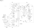
- FIG. 1 illustrates an air separation apparatus according to embodiment 1.
- the air separation apparatus 1 comprises: a main heat exchanger E1, a first rectification column (high-pressure rectification column) 2, a second rectification column (low-pressure rectification column) 4, a third rectification column (first crude argon rectification column) 5, a fourth rectification column 7 (pure argon rectification column), a first condensing portion 3, a second condensing portion 6, a third condensing portion 8, a reboiler 9, and a subcooler E2.
- the first rectification column 2 may be referred to as a high-pressure rectification column because it performs rectification at a higher pressure than the second rectification column 4, and the second rectification column 4 may be referred to as a low-pressure rectification column.
- Feed air passes through the main heat exchanger E1 and is introduced via a pipe L1 into a column bottom 21 or a lower stage of a rectification portion 23 of the first rectification column 2.
- the feed air is separated into an oxygen-rich liquid and a nitrogen-containing liquid (LIN) in the first rectification column 2.
- LIN nitrogen-containing liquid
- the first condensing portion (nitrogen condenser) 3 condenses (liquefies) nitrogen gas drawn from a column top 25 of the first rectification column 2 via a pipe L25c, and returns the condensed gas to the first rectification column 2.
- Oxygen gas constituting a portion drawn from the column top of the first condensing portion (nitrogen condenser) 3 is fed to a column bottom 41 or a lower-stage rectification portion 42 of the second rectification column 4.
- Another portion drawn from the column top of the first condensing portion 3 is introduced, via a pipe L32 and a branch pipe L321 thereof, into the main heat exchanger E1 where it undergoes heat exchange, and can then be extracted as product oxygen (oxygen).
- a further portion is introduced, via a branch pipe L322 of the pipe L32, into the main heat exchanger E1 where it undergoes heat exchange and is then expelled as a waste gas.
- a valve may be provided in one or both of the branch pipe L321 and the branch pipe L322.
- the oxygen-rich liquid is drawn from the column bottom 21 of the first rectification column 2 via a pipe L21 and undergoes heat exchange in the subcooler E2, after which it is introduced into a rectification portion or a column top of the third rectification column 5.
- a valve V2 is provided in the pipe L21 and functions as a flow rate control valve or an opening/closing gate valve.
- the nitrogen-containing liquid (LIN) is drawn from the column top 25 of the first rectification column 2 via a pipe L25b and undergoes heat exchange in the subcooler E2, after which it is introduced into an upper-stage rectification portion 44 of the second rectification column 4.
- a valve V1 is provided in the pipe L25b and functions as a flow rate control valve or an opening/closing gate valve.
- the valve V1 may be controlled by means of a control unit C8.
- the nitrogen-containing gas is drawn from the column top 25 of the first rectification column 2 via a pipe L25a and is introduced into the reboiler 9 where it condenses.
- a valve V3 is provided in the pipe L25a and functions as a flow rate control valve, an opening/closing gate valve, or a pressure regulating valve.
- the nitrogen-containing gas fed to the reboiler 9 will be described in detail below.
- the nitrogen-containing liquid (LIN) introduced into the upper-stage rectification portion 44 of the second rectification column 4 is rectified in the second rectification column 4.
- High-purity oxygen liquid drawn from the column bottom 41 of the second rectification column 4 is fed to the first condensing portion 3.
- An argon-containing oxygen-rich fluid (which may be gaseous, liquid or a gas-liquid mixture) is drawn via a pipe L42 from the lower-stage rectification portion 42 or an intermediate rectification portion 43 of the second rectification column 4, and is introduced into a column bottom 51 or a lower stage of a rectification portion 53 of the third rectification column 5 (first crude argon rectification column).
- High-purity nitrogen gas (GAN) is drawn via a pipe L45 from a column top 45 of the second rectification column 4 and is warmed by heat exchange in the subcooler E2, after which it is introduced into the main heat exchanger E1 to undergo heat exchange, and is then discharged as product nitrogen (nitrogen).
- a gas is drawn via a pipe L43 from the upper-stage rectification portion 44 or the intermediate rectification portion 43 of the second rectification column 4 and undergoes heat exchange in the subcooler E2, after which it is introduced into the main heat exchanger E1 to undergo heat exchange, and is then discharged as a waste gas.
- the waste gas introduced into the main heat exchanger E1 via the pipe L322 and the pipe L43 exits from an intermediate stage of the main heat exchanger E1 and is fed to an expansion turbine ET for use in functioning the turbine, after which it is once again returned to the main heat exchanger E1 and expelled as waste gas.
- the third rectification column 5 rectifies the argon-containing oxygen-rich fluid to obtain an argon-rich fluid.
- the argon-rich fluid (which may be gaseous, liquid or a gas-liquid mixture) is drawn out via a pipe L55 from an upper stage of the rectification portion 53 or a column top portion 55 of the third rectification column 5, and is introduced into a rectification portion 73 of the fourth rectification column 7 (pure argon rectification column).
- a rectified liquid of the argon-containing oxygen-rich fluid is drawn via a pipe L51 from the column bottom 51 of the third rectification column 5, and is returned to the lower-stage rectification portion 42 or the intermediate rectification portion 43 of the second rectification column 4.
- a rectified gas (argon gas) of the argon-containing oxygen-rich fluid is drawn via a pipe L52 from the column top 55 of the third rectification column 5, and fed to the second condensing portion 6 where it is condensed (liquefied), and then returned to the column top 55.
- a rectified liquid of the oxygen-rich liquid drawn via a pipe L61 from a lower portion of the second condensing portion 6 is introduced into the intermediate rectification portion 43 of the second rectification column 4.
- a gas from the rectified liquid of the oxygen-rich liquid drawn from the column top of the second condensing portion 6 is introduced via a pipe L62 into the intermediate rectification portion 43 of the second rectification column 4.
- An argon-rich fluid (which may be gaseous, liquid or a gas-liquid mixture) drawn from the rectification portion 53 or the column top 55 of the third rectification column 5 is introduced into the rectification portion 73 of the fourth rectification column 7 and rectified.
- Argon gas drawn from a column top 75 of the fourth rectification column 7 is introduced into the third condensing portion 8.
- Argon liquid condensed in the third condensing portion 8 is returned to the fourth rectification column 7.
- the argon liquid stored in a column bottom 71 of the fourth rectification column 7 is fed to the reboiler 9.
- the gas from the reboiler 9 is introduced into the fourth rectification column 7.
- the nitrogen-containing gas is introduced from the column top 25 of the first rectification column 2 via the pipe L25a to warmthe reboiler 9.
- the pressure of the gas fed to the pipe L25a is regulated by the valve V3.
- the nitrogen-containing gas which is condensed in the reboiler 9 is fed to the third condensing portion 8 via an introduction pipe L92.
- a decompression valve V4 is provided in the introduction pipe L92.
- the nitrogen-containing liquid (LIN) introduced into the third condensing portion 8 is utilized as cold heat in the third condensing portion 8 to condense the top gas of column 7.
- a gas (nitrogen-containing gas) is fed from the top of the third condensing portion via a recycling pipe L81 to the intermediate rectification portion 43 or the upper-stage rectification portion 44 of the second rectification column 4.
- Liquid argon (high-purity argon liquid LAr) can be extracted as product argon liquid from the lower portion of the reboiler 9 via a drawing pipe L91.
- the branch pipe L811 is provided branching from the recycling pipe L81.
- a gate valve V8 is provided in the recycling pipe L81, and a gate valve V7 is provided in the branch pipe L811.
- the control unit C8 performs control to open the gate valve V7 and close the gate valve V8 so that the nitrogen-containing liquid (LIN) drawn from the third condensing portion 8 is fed to the branch pipe L811 for a predetermined period from the start of functioning of the third condensing portion 8, and performs control to open the gate valve V8 and close the gate valve V7 so that the nitrogen-containing liquid (LIN) drawn from the third condensing portion 8 is fed to the recycling pipe L81 after the predetermined period has elapsed.
- the "predetermined period” is a time until stable functioning is achieved, for example, and it may be set by a test run or experimental measurement, etc.
- the “predetermined period” is the time until the purity reaches 99% or more, for example, when the nitrogen gas concentration in the recycling pipe L81 is measured by a nitrogen gas concentration measuring unit (not depicted).
- a specific example of the "predetermined period" is a time of 12 hours, for example.
- the branch pipe L811 merges with the pipe L43, and after the gas has undergone heat exchange in the subcooler E2, it is introduced into the main heat exchanger E1 for heat exchange, and then expelled as waste gas.
Landscapes
- Engineering & Computer Science (AREA)
- Physics & Mathematics (AREA)
- Mechanical Engineering (AREA)
- Thermal Sciences (AREA)
- General Engineering & Computer Science (AREA)
- Health & Medical Sciences (AREA)
- Emergency Medicine (AREA)
- Separation By Low-Temperature Treatments (AREA)
Abstract
Description
- The present disclosure relates to an air separation apparatus. In particular, the present disclosure relates to an air separation apparatus comprising a crude argon rectification column and a pure argon rectification column.
- Conventionally, an oxygen-rich gas-liquid fluid containing argon extracted from an air separation apparatus is fed to an argon rectification column from which high-purity product argon liquid is extracted.
-
Patent Documents 1 and 2 describe an air separation apparatus comprising: - a first rectification column having a first condenser,
- a second rectification column,
- a crude argon rectification column having a second condenser, and
- a pure argon rectification column.
-
Patent Documents - a first rectification column having a first condenser,
- a second rectification column, and
- a crude argon rectification column having a second condenser.
- A pure argon rectification column is provided in
Patent Documents 1 and 2, but there is no description of a waste gas used in the pure argon rectification column. - Patent Documents 3-5 all relate to an air separation apparatus that does not have a pure argon rectification column.
-
- Patent Document 1:
JP 6557763 B1 - Patent Document 2:
JP 2021-110466 A - Patent Document 3:
JP 6440232 B1 - Patent Document 4:
US 2019/0293347 A1 - Patent Document 5:
JP 2004-251569 A - In an air separation apparatus for simultaneously producing high-purity nitrogen and high-purity argon, the argon is produced at high purity from a feed gas (a gas containing argon, oxygen and nitrogen) fed to the pure argon rectification column, and the waste gas therefrom contains nitrogen.
- When the pure argon rectification column is configured to be capable of functioning (starting and stopping) independently of other rectification columns, this makes the piping more complex (narrow pipes, dead-end pipelines).
- There is a risk of contamination of the air separation apparatus as a result. Recovery of nitrogen gas from the waste gas is therefore a concern.
- Meanwhile, it would be desirable to recover nitrogen gas contained in the gas drawn from the condensing portion of the pure argon rectification column.
- In light of the situation described above, the objective of the present disclosure lies in providing an air separation apparatus comprising a crude argon rectification column and a pure argon rectification column, which is capable of recovering nitrogen from a gas drawn from a condensing portion of the pure argon rectification column; and a method for recovering nitrogen from the gas drawn from the condensing portion of the pure argon rectification column.
- An air separation apparatus according to the present disclosure comprises:
- a first rectification column into which feed air is introduced;
- a first condensing portion for condensing nitrogen gas drawn from a column top of the first rectification column;
- a second rectification column into which is introduced a nitrogen-containing liquid drawn from an upper stage of a rectification portion or the column top of the first rectification column (the nitrogen-containing liquid is introduced into an upper-stage rectification portion or an intermediate rectification portion );
- a third rectification column into which is introduced an argon-containing oxygen-rich fluid (which may be gaseous, liquid or a gas-liquid mixture) drawn from a lower-stage rectification portion or the intermediate rectification portion of the second rectification column ;
- a second condensing portion for condensing a gas drawn from a column top of the third rectification column;
- a fourth rectification column into which is introduced an argon-rich fluid (which may be gaseous, liquid or a gas-liquid mixture) drawn from a rectification portion (from an intermediate stage to an upper stage) or the column top (55) of the third rectification column ;
- a third condensing portion into which is introduced a gas drawn from a column top of the fourth rectification column ;
- means for sending liquid nitrogen to the third condensing portion and
- a recycling pipe for recycling nitrogen-rich gas produced by vaporising the liquid nitrogen in the third condensing portion to (the intermediate rectification portion or the upper-stage rectification portion of) the second rectification column.
- The third rectification column may be referred to as a crude argon rectification column, and the fourth rectification column may be referred to as a pure argon rectification column.
- According to other optional features:
- the nitrogen rich gas is sent to a point of the second rectification column between a upper-stage rectification portion and an intermediate rectification portion .
- the apparatus comprises means for sending all the bottom liquid of the first rectification column to the second condensing portion.
- the apparatus comprises means for removing a gaseous nitrogen product between a upper-stage rectification portion and an intermediate rectification portion of the second rectification column.
- the apparatus comprises a turbine and means for sending an oxygen rich gas to the turbine to be expanded.
- the apparatus comprises a reboiler for heating the bottom liquid of the fourth rectification column, means for withdrawing gaseous nitrogen from the first rectification column and sending the gaseous nitrogen to the reboiler of the fourth rectification column, means for removing liquid nitrogen from the reboiler and sending it to the third condensing portion.
- The first condensing portion may be provided in an upper portion of the first rectification column. The second condensing portion may be provided in an upper portion of the third rectification column. The third condensing portion may be provided in an upper portion of the fourth rectification column.
- Feed air may be introduced from a warm end of a main heat exchanger, pass through a cold end, and be introduced into a column bottom of the first rectification column (high-pressure column). The feed air may be treated in an air purification unit to remove impurities, etc. before being introduced into the main heat exchanger.
- A branch pipe branching from the recycling pipe may be provided.
- A valve may be provided in the recycling pipe or/and the branch pipe. A valve (three-way valve) may be provided at a branching position.
- The air separation apparatus may comprise a control unit for controlling opening/closing of the valve so that a gas drawn from the third condensing portion is fed to the branch pipe for a predetermined period from the start of functioning of the third condensing portion, and for controlling opening/closing of the valve so that the gas drawn from the third condensing portion (8) is fed to the recycling pipe after the predetermined period has elapsed.
- The air separation apparatus may comprise a reboiler into which is introduced a nitrogen-containing gas drawn from a rectification upper stage of the first rectification column. A drawing pipe for drawing liquid argon (high-purity argon liquid) from a lower portion of the reboiler may be provided in the reboiler. The reboiler may be provided in a lower portion of the fourth rectification column, or it may be provided outside the column.
- Otherwise liquid nitrogen from another source may be sent to the third condensing portion.
- An introduction pipe may be provided for introducing a liquid drawn from the reboiler into the third condensing portion. A decompression means may be provided in the introduction pipe.
- An oxygen-rich liquid drawn from the column bottom of the first rectification column may be introduced into a rectification upper stage or column top of the third rectification column, or into the second condensing portion
- The third rectification column may be separated into two or more columns, or it may be configured by a single column.
- The second rectification column may be separated into two or more columns, or it may be configured by a single column.
- A subcooler may also be provided, and two or more of the following liquids/gases may be introduced therein:
- a nitrogen-containing liquid which is drawn from the column top from an upper stage of the rectification portion of the first rectification column, and is introduced into the second rectification column,
- an oxygen-rich liquid which is drawn from the column bottom of the first rectification column, and is introduced into the rectification upper stage or column top of the third rectification column, the second condensing portion, or an additional rectification column,
- high-purity nitrogen gas drawn from a column top of the second rectification column,
- a waste gas drawn from an upper stage or intermediate stage of the second rectification column, and
- a waste gas (that is, used nitrogen-containing liquid) circulating through the branch pipe,
- the abovementioned two or more liquids/gases undergoing heat exchange with each other in the subcooler.
- The control unit may also serve as a device for controlling the air separation apparatus. The control unit may be configured by a dedicated device, an information processor (e.g., a cloud server, an on-premises server, or a general-purpose computer, etc.), a device for collaboration between software and hardware (a memory and a processor), and firmware, etc.
- According to the invention, there is provided a method for recovering nitrogen gas from a gas drawn from a condensing portion of a pure argon rectification column, the method comprising:
- i) Sending a cooled purified air stream to a first rectification column
- ii) Sending nitrogen enriched liquid from the first rectification column to a second rectification column having a bottom thermally linked to the top of the first rectification column
- iii) Sending a stream enriched in argon from the second rectification column to a crude argon rectification column
- iv) Sending an argon enriched stream from the crude argon rectification column to a pure argon rectification column
- v) Removing an argon rich stream from the pure argon rectification column
- vi) Vaporising liquid nitrogen in a top condenser of the pure argon rectification column and
- vii) Sending vaporised liquid nitrogen from the top condenser to the second rectification column.
- According to optional features:
- the method comprises a functioning-start time control step in which the gas drawn from the third condensing portion is not recycled for a predetermined period after the start of functioning of the third condensing portion, and the gas vaporised in the third condensing portion is recycled to the second rectification column after the predetermined period has elapsed.
- a nitrogen rich gas is removed from the first rectification column, condensed in a bottom reboiler of the fourth rectification column and vaporised in the third condensing portion.
- the gas vaporised in the third condensing portion is sent to a position between an upper-stage rectification portion and an intermediate rectification portion of the second rectification column.
- all the liquid vaporised in the third condensing portion is sent to the second rectification column.
- a gaseous nitrogen product stream is removed at a position between an upper-stage rectification portion and an intermediate rectification portion of the second rectification column.
- all the bottom liquid of the first rectification column is sent to the second condensing portion.
- The gas drawn vaporised in third condensing portion is a gas based on the nitrogen-containing gas drawn from the rectification upper stage of the first rectification column and introduced into the third condensing portion via the reboiler.
- The above method may comprise:
- a functioning-start time control step in which the gas drawn from the third condensing portion is not recycled for a predetermined period after the start of functioning of the third condensing portion, and
- the gas drawn from the third condensing portion is recycled to the second rectification column after the predetermined period has elapsed.
- The gas drawn from the third condensing portion is recycled to the second rectification column, whereby impurities in the gas can be refined (removed) in the second rectification column so that nitrogen can be recovered, and the nitrogen recovery rate can be improved.
- Furthermore, at the start of functioning of the third condensing portion (8), the gas is treated without being fed to the second rectification column, whereby the gas can be rectified after a standby for stable operation of the second rectification column.
- [
Fig. 1] Fig. 1 illustrates an air separation apparatus according toembodiment 1. - Several embodiments of the present invention will be described below. The embodiments described below are examples of the present invention. The present invention is in no way limited by the following embodiments, and also includes a number of variant modes which are implemented within a scope that does not alter the gist of the present invention. It should be noted that not all of the components described below are necessarily essential components of the present invention.
- An
air separation apparatus 1 according toembodiment 1 will be described below with the aid offig. 1 . Theair separation apparatus 1 comprises: a main heat exchanger E1, a first rectification column (high-pressure rectification column) 2, a second rectification column (low-pressure rectification column) 4, a third rectification column (first crude argon rectification column) 5, a fourth rectification column 7 (pure argon rectification column), a first condensing portion 3, asecond condensing portion 6, a third condensing portion 8, areboiler 9, and a subcooler E2. - The first rectification column 2 may be referred to as a high-pressure rectification column because it performs rectification at a higher pressure than the
second rectification column 4, and thesecond rectification column 4 may be referred to as a low-pressure rectification column. - Feed air passes through the main heat exchanger E1 and is introduced via a pipe L1 into a column bottom 21 or a lower stage of a
rectification portion 23 of the first rectification column 2. The feed air is separated into an oxygen-rich liquid and a nitrogen-containing liquid (LIN) in the first rectification column 2. - The first condensing portion (nitrogen condenser) 3 condenses (liquefies) nitrogen gas drawn from a
column top 25 of the first rectification column 2 via a pipe L25c, and returns the condensed gas to the first rectification column 2. Oxygen gas constituting a portion drawn from the column top of the first condensing portion (nitrogen condenser) 3 is fed to a column bottom 41 or a lower-stage rectification portion 42 of thesecond rectification column 4. - Another portion drawn from the column top of the first condensing portion 3 is introduced, via a pipe L32 and a branch pipe L321 thereof, into the main heat exchanger E1 where it undergoes heat exchange, and can then be extracted as product oxygen (oxygen). A further portion is introduced, via a branch pipe L322 of the pipe L32, into the main heat exchanger E1 where it undergoes heat exchange and is then expelled as a waste gas. A valve may be provided in one or both of the branch pipe L321 and the branch pipe L322.
- The oxygen-rich liquid is drawn from the
column bottom 21 of the first rectification column 2 via a pipe L21 and undergoes heat exchange in the subcooler E2, after which it is introduced into a rectification portion or a column top of thethird rectification column 5. A valve V2 is provided in the pipe L21 and functions as a flow rate control valve or an opening/closing gate valve. - The nitrogen-containing liquid (LIN) is drawn from the
column top 25 of the first rectification column 2 via a pipe L25b and undergoes heat exchange in the subcooler E2, after which it is introduced into an upper-stage rectification portion 44 of thesecond rectification column 4. - A valve V1 is provided in the pipe L25b and functions as a flow rate control valve or an opening/closing gate valve. The valve V1 may be controlled by means of a control unit C8.
- Furthermore, the nitrogen-containing gas is drawn from the
column top 25 of the first rectification column 2 via a pipe L25a and is introduced into thereboiler 9 where it condenses. - A valve V3 is provided in the pipe L25a and functions as a flow rate control valve, an opening/closing gate valve, or a pressure regulating valve. The nitrogen-containing gas fed to the
reboiler 9 will be described in detail below. - The nitrogen-containing liquid (LIN) introduced into the upper-
stage rectification portion 44 of thesecond rectification column 4 is rectified in thesecond rectification column 4. High-purity oxygen liquid drawn from thecolumn bottom 41 of thesecond rectification column 4 is fed to the first condensing portion 3. - An argon-containing oxygen-rich fluid (which may be gaseous, liquid or a gas-liquid mixture) is drawn via a pipe L42 from the lower-
stage rectification portion 42 or anintermediate rectification portion 43 of thesecond rectification column 4, and is introduced into a column bottom 51 or a lower stage of arectification portion 53 of the third rectification column 5 (first crude argon rectification column). High-purity nitrogen gas (GAN) is drawn via a pipe L45 from acolumn top 45 of thesecond rectification column 4 and is warmed by heat exchange in the subcooler E2, after which it is introduced into the main heat exchanger E1 to undergo heat exchange, and is then discharged as product nitrogen (nitrogen). - A gas is drawn via a pipe L43 from the upper-
stage rectification portion 44 or theintermediate rectification portion 43 of thesecond rectification column 4 and undergoes heat exchange in the subcooler E2, after which it is introduced into the main heat exchanger E1 to undergo heat exchange, and is then discharged as a waste gas. - In this embodiment, the waste gas introduced into the main heat exchanger E1 via the pipe L322 and the pipe L43 (the pipe L43 which also merges with a pipe L811 from the third condensing portion 8) exits from an intermediate stage of the main heat exchanger E1 and is fed to an expansion turbine ET for use in functioning the turbine, after which it is once again returned to the main heat exchanger E1 and expelled as waste gas.
- The
third rectification column 5 rectifies the argon-containing oxygen-rich fluid to obtain an argon-rich fluid. The argon-rich fluid (which may be gaseous, liquid or a gas-liquid mixture) is drawn out via a pipe L55 from an upper stage of therectification portion 53 or acolumn top portion 55 of thethird rectification column 5, and is introduced into arectification portion 73 of the fourth rectification column 7 (pure argon rectification column). - A rectified liquid of the argon-containing oxygen-rich fluid is drawn via a pipe L51 from the
column bottom 51 of thethird rectification column 5, and is returned to the lower-stage rectification portion 42 or theintermediate rectification portion 43 of thesecond rectification column 4. - A rectified gas (argon gas) of the argon-containing oxygen-rich fluid is drawn via a pipe L52 from the
column top 55 of thethird rectification column 5, and fed to thesecond condensing portion 6 where it is condensed (liquefied), and then returned to thecolumn top 55. - A rectified liquid of the oxygen-rich liquid drawn via a pipe L61 from a lower portion of the
second condensing portion 6 is introduced into theintermediate rectification portion 43 of thesecond rectification column 4. A gas from the rectified liquid of the oxygen-rich liquid drawn from the column top of thesecond condensing portion 6 is introduced via a pipe L62 into theintermediate rectification portion 43 of thesecond rectification column 4. - An argon-rich fluid (which may be gaseous, liquid or a gas-liquid mixture) drawn from the
rectification portion 53 or thecolumn top 55 of thethird rectification column 5 is introduced into therectification portion 73 of thefourth rectification column 7 and rectified. - Argon gas drawn from a
column top 75 of thefourth rectification column 7 is introduced into the third condensing portion 8. Argon liquid condensed in the third condensing portion 8 is returned to thefourth rectification column 7. The argon liquid stored in acolumn bottom 71 of thefourth rectification column 7 is fed to thereboiler 9. The gas from thereboiler 9 is introduced into thefourth rectification column 7. - The nitrogen-containing gas is introduced from the
column top 25 of the first rectification column 2 via the pipe L25a to warmthereboiler 9. The pressure of the gas fed to the pipe L25a is regulated by the valve V3. - The nitrogen-containing gas which is condensed in the
reboiler 9 is fed to the third condensing portion 8 via an introduction pipe L92. A decompression valve V4 is provided in the introduction pipe L92. The nitrogen-containing liquid (LIN) introduced into the third condensing portion 8 is utilized as cold heat in the third condensing portion 8 to condense the top gas ofcolumn 7. A gas (nitrogen-containing gas) is fed from the top of the third condensing portion via a recycling pipe L81 to theintermediate rectification portion 43 or the upper-stage rectification portion 44 of thesecond rectification column 4. - Liquid argon (high-purity argon liquid LAr) can be extracted as product argon liquid from the lower portion of the
reboiler 9 via a drawing pipe L91. - In this embodiment, the branch pipe L811 is provided branching from the recycling pipe L81. A gate valve V8 is provided in the recycling pipe L81, and a gate valve V7 is provided in the branch pipe L811.
- The control unit C8 performs control to open the gate valve V7 and close the gate valve V8 so that the nitrogen-containing liquid (LIN) drawn from the third condensing portion 8 is fed to the branch pipe L811 for a predetermined period from the start of functioning of the third condensing portion 8, and performs control to open the gate valve V8 and close the gate valve V7 so that the nitrogen-containing liquid (LIN) drawn from the third condensing portion 8 is fed to the recycling pipe L81 after the predetermined period has elapsed.
- The "predetermined period" is a time until stable functioning is achieved, for example, and it may be set by a test run or experimental measurement, etc. The "predetermined period" is the time until the purity reaches 99% or more, for example, when the nitrogen gas concentration in the recycling pipe L81 is measured by a nitrogen gas concentration measuring unit (not depicted).
- A specific example of the "predetermined period" is a time of 12 hours, for example.
- The branch pipe L811 merges with the pipe L43, and after the gas has undergone heat exchange in the subcooler E2, it is introduced into the main heat exchanger E1 for heat exchange, and then expelled as waste gas.
-
- (1) The oxygen-rich liquid drawn from the
column bottom 21 of the first rectification column 2 may undergo heat exchange in the subcooler E2 and then be introduced into theintermediate rectification portion 43 of thesecond rectification column 4. - (2) The subcooler may or may not be provided.
- (3) The main heat exchanger E1 may or may not be provided. Furthermore, a cleaning apparatus for cleaning the feed air may be provided upstream of the main heat exchanger E1.
- (4) A thermometer, pressure gauge and liquid level gauge, etc. may be provided in each of the rectification columns.
- (5) A thermometer, pressure gauge, flowmeter, and various types of valves (e.g., a pressure regulating valve, a flow rate regulating valve, a gate valve), etc. may be provided in each of the pipes.
- (6) The expansion turbine ET need not be provided.
- (7) The branch pipe L811 and the valve V7 need not be provided.
- (8) The control unit C8 may control all of the various valves (gate valve V7, gate valve V8, etc.), and, as a different embodiment, a control unit for controlling the various valves may be provided correspondingly with each of the various valves. The control unit C8 may further control each of the control units for controlling the various valves.
- In the configuration of
fig. 1 , it was confirmed by a simulation that the nitrogen recovery rate improved by 1%-2% in an example in which recycling was performed in the recycling pipe L81, as compared to a comparative example in which no recycling was performed in the recycling pipe L81 and the material was expelled as waste gas in the pipe L811. -
- 1...
- Air separation apparatus
- 2...
- First rectification column (high-pressure rectification column)
- 3...
- First condensing portion
- 4...
- Second rectification column (low-pressure rectification column)
- 5...
- Third rectification column (crude argon rectification column)
- 6...
- Second condensing portion
- 7...
- Fourth rectification column (pure argon rectification column)
- 8...
- Third condensing portion
- 9...
- Reboiler
- E1...
- Main heat exchanger
- E2...
- Subcooler
- L81...
- Recycling pipe
- L811...
- Branch pipe
- C8...
- Control unit
Claims (13)
- Air separation apparatus (1) comprising:• a first rectification column (2) into which feed air is introduced;• a first condensing portion (3) for condensing nitrogen gas drawn from a column top of the first rectification column;• a second rectification column (4) into which is introduced a nitrogen-containing liquid (L25b) drawn from an upper stage of a rectification portion or the column top of the first rectification column;• a third rectification column (5) into which is introduced an argon-containing oxygen-rich fluid (L42) drawn from a lower-stage rectification portion or an intermediate rectification portion of the second rectification column;• a second condensing portion (6) for condensing a gas drawn from a column top of the third rectification column;• a fourth rectification column (7) into which is introduced an argon-rich fluid (L35) drawn from a rectification portion or the column top of the third rectification column;• a third condensing portion (8) into which is introduced a gas drawn from a column top of the fourth rectification column;• means for sending liquid nitrogen (L92) to the third condensing portion and• a recycling pipe for recycling nitrogen rich gas (L81) produced by vaporising the liquid nitrogen in the third condensing portion to the second rectification column.
- Air separation apparatus according to claim 1, comprising:• a branch pipe (L811) branching from the recycling pipe, said branch pipe being connected to the atmosphere; and• a control unit (C8) for controlling opening/closing of a valve (V7) so that a gas vaporised in the third condensing portion (8) is fed to the branch pipe for a predetermined period from the start of functioning of the third condensing portion, and for controlling opening/closing of the valve so that the gas vaporised in the third condensing portion is fed to the recycling pipe after the predetermined period has elapsed.
- Apparatus according to Claim 1 or 2 wherein the nitrogen rich gas (L81) is sent to a point of the second rectification column between a upper-stage rectification portion (44) and an intermediate rectification portion (43).
- Apparatus according to any preceding claim comprising means for sending all the bottom liquid (L21) of the first rectification column (2) to the second condensing portion (6).
- Apparatus according to any preceding claim comprising means for removing a gaseous nitrogen product (L43) between an upper-stage rectification portion (44) and an intermediate rectification portion (43) of the second rectification column (4).
- Apparatus according to any preceding claim comprising a turbine (ET) and means for sending an oxygen rich gas (L32) to the turbine to be expanded.
- Apparatus according to any preceding claim comprising a reboiler (9) for heating the bottom liquid of the fourth rectification column (7), means for withdrawing gaseous nitrogen (L25a) from the first rectification column (2) and sending the gaseous nitrogen to the reboiler (9) of the fourth rectification column, means for removing liquid nitrogen (L92) from the reboiler and sending it to the third condensing portion.
- Method for recovering nitrogen gas from a gas drawn from a condensing portion of a pure argon rectification column, the method comprising:i) Sending a cooled purified air stream to a first rectification column (2)ii) Sending nitrogen enriched liquid (L25b) from the first rectification column to a second rectification column (4) having a bottom thermally linked to the top of the first rectification columniii) Sending a stream (L42) enriched in argon from the second rectification column (4) to a crude argon rectification column (5)iv) Sending an argon enriched stream (L55) from the crude argon rectification column to a pure argon rectification column (7)v) Removing an argon rich stream (L91) from the pure argon rectification columnvi) Vaporising liquid nitrogen (L92) in a top condenser (8) of the pure argon rectification column andvii) Sending vaporised liquid nitrogen (L81) from the top condenser to the second rectification column.
- Method according to claim 8, comprising a functioning-start time control step in which the gas (L81) drawn from the third condensing portion (8) is not recycled for a predetermined period after the start of functioning of the third condensing portion, and the gas vaporised in the third condensing portion is recycled to the second rectification column (4) after the predetermined period has elapsed.
- Method according to Claim 8 or 9 wherein a nitrogen rich gas (L25a) is removed from the first rectification column (2), condensed in a bottom reboiler (9) of the fourth rectification column and vaporised in the third condensing portion (8).
- Method according to Claim 8, 9 or 10 wherein the gas (L81) vaporised in the third condensing portion is sent to a position between an upper-stage rectification portion (44) and an intermediate rectification portion (43) of the second rectification column (4).
- Method according to any of Claims 8 to 11 wherein all the liquid vaporised in the third condensing portion (8) is sent to the second rectification column (4).
- Method according to any of Claims 8 to 12 wherein a gaseous nitrogen product stream (L43) is removed at a position between an upper-stage rectification portion (44) and an intermediate rectification portion (43) of the second rectification column (4).
Applications Claiming Priority (1)
| Application Number | Priority Date | Filing Date | Title |
|---|---|---|---|
| JP2022034094A JP7133735B1 (en) | 2022-03-07 | 2022-03-07 | air separator |
Publications (1)
| Publication Number | Publication Date |
|---|---|
| EP4242568A1 true EP4242568A1 (en) | 2023-09-13 |
Family
ID=83192297
Family Applications (1)
| Application Number | Title | Priority Date | Filing Date |
|---|---|---|---|
| EP23159690.9A Pending EP4242568A1 (en) | 2022-03-07 | 2023-03-02 | Air separation apparatus |
Country Status (6)
| Country | Link |
|---|---|
| US (1) | US12595961B2 (en) |
| EP (1) | EP4242568A1 (en) |
| JP (1) | JP7133735B1 (en) |
| KR (1) | KR20230131767A (en) |
| CN (1) | CN116717958A (en) |
| TW (1) | TW202336396A (en) |
Families Citing this family (1)
| Publication number | Priority date | Publication date | Assignee | Title |
|---|---|---|---|---|
| JP2026100904A (en) * | 2024-12-10 | 2026-06-22 | 日本酸素株式会社 | Nitrogen production method and apparatus |
Citations (7)
| Publication number | Priority date | Publication date | Assignee | Title |
|---|---|---|---|---|
| JPH0140232B2 (en) | 1982-12-09 | 1989-08-25 | Tokyo Shibaura Electric Co | |
| JPH0257763B2 (en) | 1983-09-01 | 1990-12-05 | Nippon Kokan Keishu | |
| JP2004251569A (en) | 2003-02-21 | 2004-09-09 | Hitachi Ltd | Cryogenic air separation equipment |
| CN203928597U (en) * | 2014-05-14 | 2014-11-05 | 中国海洋石油总公司 | A kind of LNG cold energy intercourse maintains the air-seperation system of continuous operation |
| US20190293347A1 (en) | 2018-03-20 | 2019-09-26 | L'air Liquide, Societe Anonyme Pour L'etude Et L'exploitation Des Procedes Georges Claude | Method and apparatus for producing product nitrogen gas and product argon |
| CN110470103A (en) * | 2019-07-16 | 2019-11-19 | 开封空分集团有限公司 | Improve the system and method for Argon recovery rate in air |
| JP2021110466A (en) | 2020-01-06 | 2021-08-02 | 日本エア・リキード合同会社 | Air separation system |
Family Cites Families (19)
| Publication number | Priority date | Publication date | Assignee | Title |
|---|---|---|---|---|
| US4433990A (en) * | 1981-12-08 | 1984-02-28 | Union Carbide Corporation | Process to recover argon from oxygen-only air separation plant |
| JPS6440232U (en) | 1987-09-01 | 1989-03-10 | ||
| US4822395A (en) * | 1988-06-02 | 1989-04-18 | Union Carbide Corporation | Air separation process and apparatus for high argon recovery and moderate pressure nitrogen recovery |
| JP3072563B2 (en) * | 1990-12-25 | 2000-07-31 | 日本酸素株式会社 | Method and apparatus for collecting high-purity liquefied nitrogen |
| US5207066A (en) * | 1991-10-22 | 1993-05-04 | Bova Vitaly I | Method of air separation |
| US5228296A (en) * | 1992-02-27 | 1993-07-20 | Praxair Technology, Inc. | Cryogenic rectification system with argon heat pump |
| JP3306517B2 (en) * | 1992-05-08 | 2002-07-24 | 日本酸素株式会社 | Air liquefaction separation apparatus and method |
| US5440884A (en) * | 1994-07-14 | 1995-08-15 | Praxair Technology, Inc. | Cryogenic air separation system with liquid air stripping |
| US5522224A (en) * | 1994-08-15 | 1996-06-04 | Praxair Technology, Inc. | Model predictive control method for an air-separation system |
| JP3935503B2 (en) * | 1995-06-20 | 2007-06-27 | 大陽日酸株式会社 | Argon separation method and apparatus |
| GB9605171D0 (en) * | 1996-03-12 | 1996-05-15 | Boc Group Plc | Air separation |
| JP3181546B2 (en) * | 1997-12-15 | 2001-07-03 | 大陽東洋酸素株式会社 | Method and apparatus for producing nitrogen and argon from air |
| DE10341552A1 (en) * | 2003-03-27 | 2004-10-07 | Linde Ag | Low temperature decomposition of air comprises regulating the argon yield whilst adjusting the throughput amount of a bypass stream |
| US8899075B2 (en) * | 2010-11-18 | 2014-12-02 | Praxair Technology, Inc. | Air separation method and apparatus |
| US8795409B2 (en) * | 2011-08-25 | 2014-08-05 | Praxair Technology, Inc. | Air separation plant control |
| CN204115392U (en) * | 2014-08-29 | 2015-01-21 | 中国空分设备有限公司 | With the full air separation units producing liquids of air supply compressor |
| JP6557763B1 (en) | 2018-08-09 | 2019-08-07 | レール・リキード−ソシエテ・アノニム・プール・レテュード・エ・レクスプロワタシオン・デ・プロセデ・ジョルジュ・クロード | Air separation device |
| JP7460973B2 (en) * | 2020-03-05 | 2024-04-03 | 日本エア・リキード合同会社 | air separation equipment |
| CN115493359A (en) * | 2022-08-31 | 2022-12-20 | 邯郸钢铁集团有限责任公司 | A Method for Improving the Operational Stability of Large Air Separation Crude Argon Column |
-
2022
- 2022-03-07 JP JP2022034094A patent/JP7133735B1/en active Active
- 2022-12-21 TW TW111149210A patent/TW202336396A/en unknown
- 2022-12-29 CN CN202211726072.5A patent/CN116717958A/en active Pending
-
2023
- 2023-01-27 KR KR1020230010723A patent/KR20230131767A/en active Pending
- 2023-03-02 EP EP23159690.9A patent/EP4242568A1/en active Pending
- 2023-03-07 US US18/118,381 patent/US12595961B2/en active Active
Patent Citations (7)
| Publication number | Priority date | Publication date | Assignee | Title |
|---|---|---|---|---|
| JPH0140232B2 (en) | 1982-12-09 | 1989-08-25 | Tokyo Shibaura Electric Co | |
| JPH0257763B2 (en) | 1983-09-01 | 1990-12-05 | Nippon Kokan Keishu | |
| JP2004251569A (en) | 2003-02-21 | 2004-09-09 | Hitachi Ltd | Cryogenic air separation equipment |
| CN203928597U (en) * | 2014-05-14 | 2014-11-05 | 中国海洋石油总公司 | A kind of LNG cold energy intercourse maintains the air-seperation system of continuous operation |
| US20190293347A1 (en) | 2018-03-20 | 2019-09-26 | L'air Liquide, Societe Anonyme Pour L'etude Et L'exploitation Des Procedes Georges Claude | Method and apparatus for producing product nitrogen gas and product argon |
| CN110470103A (en) * | 2019-07-16 | 2019-11-19 | 开封空分集团有限公司 | Improve the system and method for Argon recovery rate in air |
| JP2021110466A (en) | 2020-01-06 | 2021-08-02 | 日本エア・リキード合同会社 | Air separation system |
Also Published As
| Publication number | Publication date |
|---|---|
| US20230280093A1 (en) | 2023-09-07 |
| TW202336396A (en) | 2023-09-16 |
| JP7133735B1 (en) | 2022-09-08 |
| US12595961B2 (en) | 2026-04-07 |
| JP2023129811A (en) | 2023-09-20 |
| KR20230131767A (en) | 2023-09-14 |
| CN116717958A (en) | 2023-09-08 |
Similar Documents
| Publication | Publication Date | Title |
|---|---|---|
| CN100380079C (en) | Air fractionation process and equipment with mixing tower and krypton-xenon recovery device | |
| US7568363B2 (en) | Treating of a crude containing natural gas | |
| EP2963368B1 (en) | Air separation method and air separation apparatus | |
| EP0538117A1 (en) | Process and Apparatus for the mixed production of high and low purity oxygen | |
| JP2003165712A (en) | Method and apparatus for producing krypton and / or xenon by low-temperature air separation | |
| RU2319084C2 (en) | Method and device for inert gas and oxygen production by cryogenic air distillation | |
| JPH03186183A (en) | Manufacture of nitrogen | |
| IE75689B1 (en) | Production of nitrogen of ultra-high purity | |
| US20240353173A1 (en) | Ultra-high-purity oxygen production method and ultra-high-purity oxygen production apparatus | |
| JPS62217090A (en) | Separation of gassy mixture | |
| KR20010105207A (en) | Cryogenic air separation system with split kettle recycle | |
| KR940015444A (en) | Cryogenic Air Separation Method and Apparatus | |
| US12595961B2 (en) | Air separation apparatus | |
| AU643232B2 (en) | Cryogenic air separation process and apparatus | |
| JPH06249575A (en) | Cryogenic separation of air | |
| ATE288064T1 (en) | METHOD AND DEVICE FOR SEPARATING AIR BY LOW TEMPERATURE DISTILLATION | |
| JP2007064617A (en) | Method of manufacturing krypton and/or xenon by cryogenic air separation | |
| US20240353174A1 (en) | Dual temperature liquid oxygen subcooling in an air separation unit | |
| EP0539268A1 (en) | Process for removing hydrogen by cryogenic distillation in the production of high purity nitrogen | |
| CN101218479B (en) | Method and apparatus for producing crude neon gas | |
| JPH10153384A (en) | Ultra-pure liquid oxygen production method | |
| CN113465292B (en) | Method for increasing yield of krypton/xenon in air rectification device | |
| US10539365B2 (en) | Method and apparatus for cryogenic separation of a mixture containing at least carbon monoxide, hydrogen and nitrogen | |
| JPH0399190A (en) | Method of manufacturing oxygen | |
| US10006699B2 (en) | Method for denitrogenation of natural gas with or without helium recovery |
Legal Events
| Date | Code | Title | Description |
|---|---|---|---|
| PUAI | Public reference made under article 153(3) epc to a published international application that has entered the european phase |
Free format text: ORIGINAL CODE: 0009012 |
|
| STAA | Information on the status of an ep patent application or granted ep patent |
Free format text: STATUS: THE APPLICATION HAS BEEN PUBLISHED |
|
| AK | Designated contracting states |
Kind code of ref document: A1 Designated state(s): AL AT BE BG CH CY CZ DE DK EE ES FI FR GB GR HR HU IE IS IT LI LT LU LV MC ME MK MT NL NO PL PT RO RS SE SI SK SM TR |
|
| STAA | Information on the status of an ep patent application or granted ep patent |
Free format text: STATUS: REQUEST FOR EXAMINATION WAS MADE |
|
| 17P | Request for examination filed |
Effective date: 20240313 |
|
| RBV | Designated contracting states (corrected) |
Designated state(s): AL AT BE BG CH CY CZ DE DK EE ES FI FR GB GR HR HU IE IS IT LI LT LU LV MC ME MK MT NL NO PL PT RO RS SE SI SK SM TR |