EP4242490B1 - Nut and ball screw device comprising the same - Google Patents
Nut and ball screw device comprising the same Download PDFInfo
- Publication number
- EP4242490B1 EP4242490B1 EP22879575.3A EP22879575A EP4242490B1 EP 4242490 B1 EP4242490 B1 EP 4242490B1 EP 22879575 A EP22879575 A EP 22879575A EP 4242490 B1 EP4242490 B1 EP 4242490B1
- Authority
- EP
- European Patent Office
- Prior art keywords
- peripheral side
- seat surface
- axial direction
- main body
- outer peripheral
- Prior art date
- Legal status (The legal status is an assumption and is not a legal conclusion. Google has not performed a legal analysis and makes no representation as to the accuracy of the status listed.)
- Active
Links
Images











Classifications
-
- F—MECHANICAL ENGINEERING; LIGHTING; HEATING; WEAPONS; BLASTING
- F16—ENGINEERING ELEMENTS AND UNITS; GENERAL MEASURES FOR PRODUCING AND MAINTAINING EFFECTIVE FUNCTIONING OF MACHINES OR INSTALLATIONS; THERMAL INSULATION IN GENERAL
- F16H—GEARING
- F16H25/00—Gearings comprising primarily only cams, cam-followers and screw-and-nut mechanisms
- F16H25/18—Gearings comprising primarily only cams, cam-followers and screw-and-nut mechanisms for conveying or interconverting oscillating or reciprocating motions
- F16H25/20—Screw mechanisms
- F16H25/22—Screw mechanisms with balls, rollers, or similar members between the co-operating parts; Elements essential to the use of such members
- F16H25/2204—Screw mechanisms with balls, rollers, or similar members between the co-operating parts; Elements essential to the use of such members with balls
- F16H25/2214—Screw mechanisms with balls, rollers, or similar members between the co-operating parts; Elements essential to the use of such members with balls with elements for guiding the circulating balls
- F16H25/2223—Cross over deflectors between adjacent thread turns, e.g. S-form deflectors connecting neighbouring threads
-
- F—MECHANICAL ENGINEERING; LIGHTING; HEATING; WEAPONS; BLASTING
- F16—ENGINEERING ELEMENTS AND UNITS; GENERAL MEASURES FOR PRODUCING AND MAINTAINING EFFECTIVE FUNCTIONING OF MACHINES OR INSTALLATIONS; THERMAL INSULATION IN GENERAL
- F16H—GEARING
- F16H25/00—Gearings comprising primarily only cams, cam-followers and screw-and-nut mechanisms
- F16H25/18—Gearings comprising primarily only cams, cam-followers and screw-and-nut mechanisms for conveying or interconverting oscillating or reciprocating motions
- F16H25/20—Screw mechanisms
- F16H25/22—Screw mechanisms with balls, rollers, or similar members between the co-operating parts; Elements essential to the use of such members
- F16H25/2204—Screw mechanisms with balls, rollers, or similar members between the co-operating parts; Elements essential to the use of such members with balls
- F16H25/2214—Screw mechanisms with balls, rollers, or similar members between the co-operating parts; Elements essential to the use of such members with balls with elements for guiding the circulating balls
- F16H25/2219—Axially mounted end-deflectors
Definitions
- the present invention relates to a nut and a ball screw device.
- the ball screw device includes a nut, a screw shaft passing through the nut, and a plurality of balls rolling along a raceway between the nut and the screw shaft.
- the nut includes a nut main body and a circulation component.
- the circulation component is a component that causes a ball that has moved from one end of the raceway to the other end of the raceway to circulate to the one end of the raceway.
- a middle deflector can be exemplified.
- the middle deflector is typically arranged on a recessed part disposed on an outer peripheral surface of the nut main body.
- a through hole extending from an end face of the nut main body in an axial direction is disposed on each of the nut main body and the middle deflector. Additionally, a pin is inserted into the through hole. Thus, the middle deflector is hooked by the pin, and is not detached from the nut main body.
- JP 2021/188687 A discloses a ball screw device allowing smooth circulation of a ball and having a fixing structure of a circulation component.
- JP 2021-032364 A discloses a ball circulation component having high durability and a little roughness on a surface of an inner wall of a ball circulation passage due to a metal powder injection molding method, and facilitating management of the state of the inner wall.
- Patent Literature 1 Japanese Patent No. 6511463
- the fixing method using the pin increases the number of components. Additionally, through holes are required for the nut main body and the circulation component, so that a layout thereof is limited. Thus, there is a demand for development of a nut that can fix the circulation component without using the pin.
- the present invention has been made in view of such a situation, and aims at providing a nut and a ball screw device that can suppress increase in the number of components.
- a nut according to a first aspect of the present invention and described in claim 1 comprising: a nut main body having a cylindrical shape through which a screw shaft passes; and a circulation component assembled to the nut main body, wherein the nut main body comprises: a housing part that is an indentation disposed on an outer peripheral surface of the nut main body and has a bow shape when viewed from an axial direction parallel with the screw shaft; a seat surface forming a bottom surface of the housing part; a through hole passing through the seat surface and an inner peripheral surface of the nut main body; and a pair of side surfaces opposed to each other that are arranged on both sides in the axial direction parallel with the screw shaft with respect to the housing part, a direction parallel with the seat surface when viewed from the axial direction is a seat surface direction, a direction perpendicular to the seat surface, which is the direction that the seat surface faces, is a first vertical direction
- the circulation component comprises: a circulation component main body arranged in the housing part and the through
- each of the inner peripheral side component and the outer peripheral side component has one arm part.
- each of the inner peripheral side component and the outer peripheral side component does not fall down to the through hole, and is not detached from the nut main body.
- the circulation component according to the present disclosure is constituted of two components (the inner peripheral side component and the outer peripheral side component), but division surfaces of the two components are not orthogonal to the axial direction.
- the division surface of the circulation component is oriented in a direction orthogonal to the axial direction, a tongue is divided in the axial direction, and strength of the tongue is lowered.
- the tongue according to the present disclosure is disposed integrally with the inner peripheral side component without being divided. Accordingly, the strength of the tongue is maintained, and the ball can be smoothly scooped up.
- a nut according to a second aspect of the present invention and as described in claim 2 comprising: a nut main body having a cylindrical shape through which a screw shaft passes; and a circulation component assembled to the nut main body, wherein the nut main body comprises: a housing part that is an indentation disposed on an outer peripheral surface of the nut main body and has a bow shape when viewed from an axial direction parallel with the screw shaft; a seat surface forming a bottom surface of the housing part; a through hole passing through the seat surface and an inner peripheral surface of the nut main body; and a pair of side surfaces opposed to each other that are arranged on both sides in the axial direction parallel with the screw shaft with respect to the housing part, a direction parallel with the seat surface when viewed from the axial direction is a seat surface direction, a direction perpendicular to the seat surface, which is the direction that the seat surface faces, is a first vertical direction
- the circulation component comprises: a circulation component main body arranged in the housing part and the
- the caulking part is hooked by the recessed part.
- the circulation component is not displaced in the first vertical direction. That is, the circulation component is not detached from the nut main body.
- the outer peripheral side component includes two arm parts.
- the inner peripheral side component a projection thereof is hooked by a groove part, so that the inner peripheral side component is not displaced in a direction parallel to a perpendicular with respect to a seat surface.
- the inner peripheral side component does not fall down to the through hole.
- the tongue according to the present invention is disposed integrally with the inner peripheral side component without being divided. Accordingly, the strength of the tongue is maintained, and the ball can be smoothly scooped up.
- the division surface includes: an oblique surface along a direction parallel with the tangential direction when viewed from the axial direction, the oblique surface positioned to be closer to one side in the seat surface direction toward the first vertical direction; and a vertical surface that is arranged to be closer to one side in the seat surface direction than the oblique surface, and extends in the first vertical direction, the projection and the groove part are disposed on the vertical surface, and movement of the inner peripheral side component is regulated by the oblique surface, the movement in a direction of releasing engagement between the projection and the groove part.
- the pair of side surfaces include: a first side surface arranged on one side in the axial direction with respect to the circulation component; and a second side surface arranged on the other side in the axial direction with respect to the circulation component, the rib includes: a first rib extending along the first side surface; and a second rib extending along the second side surface, and the caulking part includes: a first caulking part that is part of the first rib and caulked to the first side surface; and a second caulking part that is part of the second rib and caulked to the second side surface.
- the seat surface includes an expanded seat surface that is an edge of the through hole, and arranged in the axial direction with respect to the through hole, and the inner peripheral side component includes an expanded seated surface abutting on the expanded seat surface.
- each of the inner peripheral side rolling surface of the inner peripheral side component of the circulation component and the outer peripheral side rolling surface of the outer peripheral side component is a groove surface.
- the outer peripheral side rolling surface is a plane.
- the nut main body includes a positioning hole that is recessed in the axial direction from the side surface, and opens to an outer peripheral surface of the nut main body, and the circulation component main body includes a positioning projection projecting in the axial direction to be inserted into the positioning hole.
- the circulation component is not displaced in the seat surface direction.
- a ball screw device comprising: the nut described above; a screw shaft passing through the nut; and a plurality of balls arranged between the nut and the screw shaft.
- the circulation component is not detached from the nut main body.
- the pin for fixing the circulation component is not required, and increase in the number of components can be suppressed.
- FIG. 1 is a side view of a ball screw device according to a first embodiment viewed from a direction orthogonal to an axial direction.
- a ball screw device 100 includes a nut 101, a screw shaft 102 passing through the nut 101, and a plurality of balls 103 (refer to FIG. 2 ) arranged between the nut 101 and the screw shaft 102.
- the screw shaft 102 is a cylindrical component manufactured with a steel material.
- a spiral-shaped outer peripheral raceway surface 102a is disposed on an outer peripheral surface of the screw shaft 102.
- a direction parallel with an axis O of the screw shaft 102 is referred to as an axial direction.
- the ball screw device 100 is a device that converts rotational motion into linear motion, or converts linear motion into rotational motion.
- an inner ring 104 is disposed on an outer peripheral surface of the nut 101.
- the inner ring 104 is arranged to be close to an end in the axial direction of the outer peripheral surface of the nut 101.
- a direction in which the inner ring 104 is arranged is referred to as a first axial direction (one side of the axial direction) X1.
- An opposite direction of the first axial direction X1 is referred to as a second axial direction (the other side of the axial direction) X2.
- the inner ring 104 is a component of a bearing that supports the nut 101 in a rotatable manner.
- An outer peripheral raceway surface 105 on which the ball rolls is disposed on an outer peripheral surface of the inner ring 104.
- the nut 101 is supported by a housing and the like (not illustrated) in a rotatable manner, and the screw shaft 102 linearly moves in the axial direction.
- the ball screw device 100 according to the present embodiment has a specification for converting rotational motion into linear motion.
- the present embodiment exemplifies the nut with which the inner ring is integrally formed, but a nut with which an inner ring is not integrally formed may be used in the present invention.
- the present invention may also be applied to a ball screw device that converts linear motion into rotational motion.
- FIG. 2 is a cross-sectional view of the nut according to the first embodiment cut along the axial direction.
- the nut 101 includes a nut main body 1, and a middle deflector (circulation device) 30 and an end deflector 110 assembled to the nut main body 1.
- the nut main body 1 is a component having a cylindrical shape manufactured with a steel material.
- a spiral-shaped inner peripheral raceway surface 3 is disposed on an inner peripheral surface 2 of the nut main body 1.
- a space between the inner peripheral raceway surface 3 and the outer peripheral raceway surface 102a is a spiral-shaped raceway 106.
- the balls 103 are arranged on the raceway 106. When the nut 101 rotates, the ball 103 rolls on the inner peripheral raceway surface 3 and the outer peripheral raceway surface 102a to move in a spiral direction along the raceway 106.
- a first housing part (housing part) 5 that is recessed inwardly in a radial direction from the outer peripheral surface 4 of the nut main body 1.
- a second housing part 7 On an end face 6 in the first axial direction X1 of the nut main body 1, disposed is a second housing part 7 that is recessed in the second axial direction X2.
- a return path 8 On the nut main body 1, disposed is a return path 8 that passes therethrough in the axial direction and communicates between the first housing part 5 and the second housing part 7.
- the middle deflector 30 is housed in the first housing part 5.
- the end deflector 110 is housed in the second housing part 7.
- the ball 103 that has moved in the second axial direction X2 along the raceway 106 is scooped up by the middle deflector 30, and guided to the return path 8.
- the ball 103 rolls in the return path 8 in the first axial direction X1, and enters an inner part of the end deflector 110.
- the end deflector 110 then circulates the ball 103 to an end in the first axial direction X1 of the raceway 106.
- the end deflector 110 scoops up the ball 103 from the raceway 106, and the middle deflector 30 circulates the ball 103 to a rolling path. Due to this, the ball 103 continuously rolls on the raceway 106.
- the middle deflector 30 and the end deflector 110 are provided as two circulation components, but both of the two circulation components may be middle deflectors (circulation components) in the present invention.
- middle deflectors circulation components
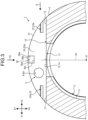
- FIG. 3 is a cross-sectional view of the nut main body cut along a line III-III in FIG. 1 , the cross section of which being viewed from an arrow direction.
- the nut main body 1 includes the first housing part 5, a seat surface 10 forming a bottom surface of the first housing part 5, a through hole 17 passing through the seat surface 10, and a pair of side surfaces 20 (only one of them is illustrated in FIG. 3 ) arranged on both sides in the axial direction of the first housing part 5.
- the first housing part 5 is a space having a bow shape when viewed from the axial direction.
- the bow shape is a shape obtained by combining a circular arc part overlapping with the outer peripheral surface 4 of the nut main body 1 and a linear part (a linear part connecting between both ends of the circular arc part) overlapping with the seat surface 10 when viewed from the axial direction.
- the seat surface 10 is a surface on which the middle deflector 30 abuts (is seated).
- the seat surface 10 is a plane orthogonal to a virtual line K1 extending from the axis O in the radial direction when viewed from the axial direction.
- a direction in which the seat surface 10 extends (a direction orthogonal to each of the virtual line K1 and the axial direction) is referred to as a seat surface direction.
- a direction parallel with the virtual line K1 (a direction perpendicular to the seat surface) is referred to as a vertical direction.
- One side of the vertical direction that the seat surface 10 faces is referred to as a first vertical direction Z1.
- first vertical direction Z1 An opposite direction of the first vertical direction Z1 is referred to as a second vertical direction Z2.
- the seat surface 10 (first housing part 5) extends in a direction orthogonal to the axis O when viewed from an outer peripheral side (refer to FIG. 4 ).
- the through hole 17 extends in the vertical direction, and passes through the seat surface 10 and the inner peripheral surface 2 of the nut main body 1.
- the through hole 17 passes through a center part in the seat surface direction of the seat surface 10.
- the seat surface 10 is partitioned into a first seat surface 11 arranged on one side of the seat surface direction with respect to the through hole 17 and a second seat surface 12 arranged on the other side of the seat surface direction with respect to the through hole 17.
- a direction in which the first seat surface 11 is arranged when viewed from the through hole 17 is referred to as a first seat surface direction Y1.
- An opposite direction of the first seat surface direction Y1 is referred to as a second seat surface direction Y2.
- FIG. 4 is a side view viewed from an arrow IV direction in FIG. 3 .
- the through hole 17 has a rectangular shape when viewed from the first vertical direction Z1.
- the through hole 17 passes through a center part in the axial direction of the seat surface 10.
- a length L1 in the axial direction of the through hole 17 is shorter than a length L2 in the axial direction of the seat surface 10.
- the seat surface 10 includes an expanded seat surface 13 that forms an edge 17a of the through hole 17 and is adjacent to both sides in the axial direction of the through hole 17.
- Each of four corner parts of the through hole 17 according to the present embodiment has a right-angled shape, but may be a corner R part.
- the through hole 17 does not necessarily have a rectangular shape.
- the expanded seat surface 13 includes a first expanded seat surface 14 arranged in the first axial direction X1 with respect to the through hole 17, and a second expanded seat surface 15 arranged in the second axial direction X2 with respect to the through hole 17.
- Each of the first expanded seat surface 14 and the second expanded seat surface 15 extends in the seat surface direction, and both ends thereof are connected to the first seat surface 11 and the second seat surface 12, respectively.
- the expanded seat surface 13 is not necessarily continued in the seat surface direction as in the embodiment. It is sufficient that the middle deflector 30 can abut (be seated) on the expanded seat surface 13.
- the expanded seat surface according to the present invention may be an expanded seat surface the part of which in the seat surface direction is notched, the expanded seat surface not continuing in the seat surface direction.
- the pair of side surfaces 20 includes a first side surface 20a arranged in the first axial direction X1 with respect to the seat surface 10, and a second side surface 20b arranged in the second axial direction X2 with respect to the seat surface 10.
- the first side surface 20a and the second side surface 20b are opposed to each other in the axial direction.
- Technical content for the first side surface 20a or the second side surface 20b will be described using the "first side surface 20a" or the "second side surface 20b" as a subject.
- the side surface 20 has a bow shape.
- the side surface 20 has an outer peripheral edge part 21 having a circular arc shape.
- a recessed part 22 that is recessed in the axial direction from the side surface 20 and extends in the seat surface direction.
- One end of the recessed part 22 extends to the outer peripheral edge part 21.
- the recessed part 22 is opened toward the first housing part 5 and an outer peripheral side of the nut main body 1.
- Two recessed parts 22 are disposed for the one side surface 20.
- One of the two recessed parts 22 is arranged in the first seat surface direction Y1 with respect to the through hole 17, and is opened in the first seat surface direction Y1 by notching the outer peripheral edge part 21.
- the other one of the two recessed parts 22 is arranged in the second seat surface direction Y2 with respect to the through hole 17, and is opened in the second seat surface direction Y2 by notching the outer peripheral edge part 21. That is, the two recessed parts 22 disposed on the one side surface 20 are distributed to one side and the other side in the seat surface direction across the through hole 17 as a boundary.
- FIG. 5 is a side view viewed from an arrow V direction in FIG. 3 .
- the recessed part 22 is separated from the seat surface 10 in the first vertical direction Z1.
- a cross-sectional shape of the recessed part 22 is a triangular shape.
- an inner surface of the recessed part 22 includes a first oblique surface 23 that becomes more distant from the first housing part 5 toward the first vertical direction Z1, and a second oblique surface 24 that comes closer to the first housing part 5 toward the first vertical direction Z1.
- the recessed part 22 disposed on the first side surface 20a is referred to as a first recessed part 22a
- the recessed part 22 disposed on the second side surface 20b is referred to as a second recessed part 22b.
- the first oblique surface 23 and the second oblique surface 24 disposed on the first recessed part 22a are assumed to be a first oblique surface 23a and a second oblique surface 24a, respectively.
- the first oblique surface 23 and the second oblique surface 24 disposed on the first recessed part 22a are assumed to be a first oblique surface 23b and a second oblique surface 24b, respectively.
- an opening 8a as an entrance and exit of the return path 8, and a positioning hole 26 are disposed on the first side surface 20a.
- the positioning hole 26 is a hole that is recessed in the first axial direction X1 from the first side surface 20a.
- the positioning hole 26 is also opened toward the outer peripheral surface 4 of the nut main body 1.
- An inner surface of the positioning hole 26 includes a pair of opposing surfaces 26a holding the positioning hole 26 in the seat surface direction, a side surface 26b arranged in the first axial direction X1 with respect to the positioning hole 26, and a bottom surface 26c arranged in the second vertical direction Z2 with respect to the positioning hole 26.
- FIG. 6 is an enlarged view of the middle deflector in FIG. 1 and the surroundings thereof.
- the middle deflector 30 is a component made of metal manufactured by using a method such as a metal powder injection molding method, cutting work, or forging. As illustrated in FIG. 6 , the middle deflector 30 is arranged in the first housing part 5. Thus, when viewed from the outer peripheral side, the middle deflector 30 extends in the same direction (a direction orthogonal to the axis O, refer to FIG. 4 ) as the first housing part 5 (seat surface 10).
- the middle deflector 30 includes a deflector main body (circulation component main body) 31, an arm part 50 projecting from the deflector main body 31 in the seat surface direction, a rib 60 projecting from the arm part 50 in the first vertical direction Z1, and a caulking part 70 caulking part of the rib 60.
- the caulking part 70 is generated by caulking the rib 60 at the time of assembling the middle deflector 30 to the nut main body 1.
- the caulking part 70 is not illustrated in the drawing illustrating the middle deflector 30 before assembly.
- FIG. 7 is a cross-sectional view along arrows of a line VII-VII in FIG. 6 .
- a ball passage 34 through which the ball 103 passes is disposed inside the deflector main body 31.
- the deflector main body 31 includes a main body part 32 arranged in the first housing part 5 and a scoop-up part 33 arranged in the through hole 17.
- the ball passage 34 extends in a tangential direction (refer to a virtual line K2) of a virtual circle C obtained by connecting centers of the balls 103 on the raceway 106.
- a tongue 35 for scooping up the ball 103 from the raceway 106 is disposed on the scoop-up part 33.
- An outer peripheral surface 32a in the first vertical direction Z1 of the main body part 32 has a circular arc shape.
- the outer peripheral surface 32a of the main body part 32 overlaps with the outer peripheral surface 4 of the nut main body 1. That is, a distance from the axis O to the outer peripheral surface 32a of the middle deflector 30 is the same as an outer diameter of the nut main body 1. Thus, the middle deflector 30 does not project from the first housing part 5.
- FIG. 8 is a perspective view of the middle deflector before caulking according to the first embodiment obliquely viewed from the first vertical direction.
- FIG. 9 is a perspective view of the middle deflector before caulking according to the first embodiment obliquely viewed from the second vertical direction.
- FIG. 10 is a cross-sectional view along arrows of a line X-X in FIG. 6 .
- FIG. 11 is a cross-sectional view along arrows of a line XI-XI in FIG. 6 .
- FIG. 12 is a side view viewed from an arrow XII direction in FIG. 6 .
- the main body part 32 includes a first opposing surface 36 as a side surface facing the first axial direction X1.
- the first opposing surface 36 is opposed to the first side surface 20a.
- An opening 37 as the entrance and exit of the ball passage 34 is disposed on the first opposing surface 36.
- the opening 37 continues (is adjacent) to the opening 8a of the return path 8 in the axial direction. Due to this, the ball 103 can move from the ball passage 34 to the return path 8, or move from the return path 8 to the ball passage 34.
- R-chamfering is performed on the opening 8a and the opening 37 (refer to FIG. 2 and FIG. 10 ).
- corner chamfering may be performed instead of R-chamfering.
- a positioning projection 38 projecting in the first axial direction X1 is disposed on the first opposing surface 36.
- the positioning projection 38 has a quadrangular prism shape. As illustrated in FIG. 6 , the positioning projection 38 is inserted into the positioning hole 26. The positioning projection 38 abuts on the pair of opposing surfaces 26a of the positioning hole 26. Due to this, the middle deflector 30 is regulated not to be displaced from a predetermined assembly position in the seat surface direction.
- a distal end surface 38a of the positioning projection 38 is separated from the side surface 26b of the positioning hole 26. That is, a gap S10 is generated between the distal end surface 38a and the side surface 26b. Due to this, in a case in which the positioning projection 38 is manufactured to have a larger projecting amount than a predetermined projecting amount, a manufacturing error thereof is absorbed by the gap S10. In other words, it is possible to avoid a situation in which the positioning projection 38 abuts on the side surface 26b of the positioning hole 26, and the first side surface 20a is separated from the first opposing surface 36.
- Separation between the first side surface 20a and the first opposing surface 36 causes separation between the opening 8a of the return path 8 and the opening 37 of the ball passage 34, and the ball 103 is not smoothly delivered.
- the first side surface 20a abuts on the first opposing surface 36.
- a bottom surface 38b of the positioning projection 38 is separated from the bottom surface 26c of the positioning hole 26. That is, a gap S11 is generated between the bottom surface 38b and the bottom surface 26c. Due to this, in a case in which the positioning projection 38 is manufactured to have a thickness in the vertical direction larger than a predetermined amount, a manufacturing error thereof is absorbed by the gap S11. Accordingly, it is possible to avoid a situation in which the positioning projection 38 abuts on (is hooked by) a bottom surface 26d of the positioning hole 26, and the middle deflector 30 is not seated (does not abut) on the seat surface 10.
- the positioning projection 38 and the positioning hole 26 are disposed only in the first axial direction X1 with respect to the middle deflector 30. Due to this, at the time of arranging the middle deflector 30 in the first housing part 5, it is possible to avoid a situation in which the middle deflector 30 is erroneously arranged so that the positioning projection 38 faces the second axial direction X2 (the opening 37 faces the second axial direction).
- a length L3 in the seat surface direction of the main body part 32 is longer than a length L4 in the seat surface direction of the scoop-up part 33.
- the main body part 32 includes a seated surface 40 that faces the second vertical direction Z2 and abuts (is seated) on the seat surface 10.
- the seated surface 40 includes a first seated surface 41 that abuts on the first seat surface 11 and a second seated surface 42 that abuts on the second seat surface 12. That is, the middle deflector 30 includes seated surfaces 40 on both sides in the seat surface direction across the through hole 17.
- a length L5 in the axial direction of the main body part 32 is longer than a length L6 in the axial direction of the scoop-up part 33.
- the seated surface 40 includes an expanded seated surface 43 arranged in the axial direction with respect to the scoop-up part 33.
- the expanded seated surface 43 includes a first expanded seated surface 44 arranged in the first axial direction X1 with respect to the scoop-up part 33, and a second expanded seated surface 45 arranged in the second axial direction X2 with respect to the scoop-up part 33.
- the first expanded seated surface 44 abuts on the first expanded seat surface 14 of the seat surface 10.
- the second expanded seated surface 45 abuts on the second expanded seat surface 15.
- the main body part 32 includes a second opposing surface 46 as a side surface facing the second axial direction X2.
- the second opposing surface 46 is opposed to the second side surface 20b.
- the second opposing surface 46 is a plane. Due to a tolerance, the length L5 in the axial direction of the main body part 32 is slightly smaller than a width L7 in the axial direction of the first housing part 5. That is, a minute gap (not illustrated) is generated between the first side surface 20a and the first opposing surface 36, or between the second side surface 20b and the second opposing surface 46, or between both of them. Due to this, the middle deflector 30 can be securely housed in the first housing part 5.
- the arm part 50 includes a first arm part 51 extending in the first seat surface direction Y1 from the main body part 32 and a second arm part 52 extending in the second seat surface direction Y2 from the main body part 32.
- the first arm part 51 includes a first seated surface 53 for the arm part as a side surface facing the second vertical direction Z2.
- the second arm part 52 includes a second seated surface 54 for the arm part as a side surface facing the second vertical direction Z2.
- the first seated surface 53 for the arm part abuts on the first seat surface 11.
- the second seated surface 54 for the arm part abuts on the second seat surface 12.
- the rib 60 As illustrated in FIG. 6 , the rib 60 is disposed on each of the first arm part 51 and the second arm part 52. Thus, the following describes the rib 60 disposed on the second arm part 52, but the rib 60 disposed on the first arm part 51 will not be described.
- the rib 60 is a projection that projects from a plane 55 facing the first vertical direction Z1 of the second arm part 52 and extends in a linear shape in the seat surface direction.
- a length in the seat surface direction of the rib 60 is the same as that of the second arm part 52.
- An end part in the first seat surface direction Y1 of the rib 60 is connected to the main body part 32 (deflector main body 31).
- the end part of the rib 60 connected to the main body part 32 is referred to as a base part 60a, and an end part thereof on the opposite side is referred to as a distal end part 60b.
- the rib 60 includes a first rib 61 extending along an edge in the first axial direction X1 of the plane 55, and a second rib 62 extending along an edge in the second axial direction X2 of the plane 55.
- the first rib 61 extends along the first side surface 20a, and is adjacent to the first recessed part 22a in the axial direction (refer to FIG. 14 ).
- the second rib 62 extends along the second side surface 20b, and is adjacent to the second recessed part 22b of the second side surface 20b in the axial direction (refer to FIG. 14 ).
- the caulking part 70 is formed by caulking the rib 60 extending along the side surface 20 to the side surface 20.
- the caulking part 70 is disposed only at the distal end part 60b of the rib 60.
- the caulking part 70 includes a first caulking part 71 disposed on the first rib 61 and a second caulking part 72 disposed on the second rib 62.
- the first caulking part 71 enters the first recessed part 22a.
- the first caulking part 71 has a shape along an inner surface of the first recessed part 22a.
- the first caulking part 71 is inclined to be positioned in the first axial direction X1 toward the first vertical direction Z1 from the plane 55.
- a side surface 71a facing the first axial direction X1 of the first caulking part 71 abuts on the first oblique surface 23a.
- An end face 71b facing the first vertical direction Z1 of the first caulking part 71 abuts on the second oblique surface 24a.
- the second caulking part 72 enters the second recessed part 22b.
- the second caulking part 72 has a shape along an inner surface of the second recessed part 22b. Specifically, the second caulking part 72 is inclined to be positioned in the second axial direction X2 toward the first vertical direction Z1 from the plane 55. A side surface 72a facing the second axial direction X2 of the second caulking part 72 abuts on the first oblique surface 23b. An end face 72b facing the first vertical direction Z1 of the second caulking part 72 abuts on the second oblique surface 24b. As described above, the first caulking part 71 and the second caulking part 72 are inclined to be separated from each other in the axial direction toward the first vertical direction Z1.
- the middle deflector 30 is obtained by combining two components (an inner peripheral side component 81 and an outer peripheral side component 82) divided along a division surface 80.
- the division surface 80 extends in the axial direction.
- the division surface 80 is parallel with a tangent line (refer to the virtual line K2) with respect to the virtual circle C. That is, the division surface 80 is inclined to be positioned in the first vertical direction Z1 toward the first seat surface direction Y1.
- the component arranged on an inner peripheral side of the division surface 80 is referred to as the inner peripheral side component 81
- the component arranged on an outer peripheral side of the division surface 80 is referred to as the outer peripheral side component 82.
- Configurations of the middle deflector 30 are distributed to the inner peripheral side component 81 and the outer peripheral side component 82 across the division surface 80 as a boundary line.
- the inner peripheral side component 81 includes the first arm part 51, the tongue 35, and the expanded seated surface 43 (refer to FIG. 9 ).
- the outer peripheral side component 82 includes the second arm part 52.
- an end face of the inner peripheral side component 81 extending along the division surface 80 is referred to as an inner peripheral side division surface 83.
- An end face of the outer peripheral side component 82 extending along the division surface 80 is referred to as an outer peripheral side division surface 84.
- the division surface 80 overlaps with an outer peripheral side of the ball passage 34. Due to this, as illustrated in FIG. 11 , an inner peripheral side rolling surface 85 as a C-shaped or U-shaped groove opening in the first vertical direction Z1 is disposed on the inner peripheral side division surface 83 of the inner peripheral side component 81.
- the outer peripheral side division surface 84 of the outer peripheral side component 82 is a plane. Part of the outer peripheral side division surface 84 forms an outer peripheral side rolling surface 86 that covers the inner peripheral side rolling surface 85 from the first vertical direction Z1.
- the outer peripheral side division surface 84 is a plane, so that manufacture of the outer peripheral side component 82 is facilitated.
- the inner peripheral side component 81 and the outer peripheral side component 82 are separately manufactured.
- the inner peripheral side division surface 83 is joined to the outer peripheral side division surface 84, and the inner peripheral side component 81 is integrated with the outer peripheral side component 82.
- As a joining method heat welding, bonding, and the like can be exemplified.
- an end part in the first seat surface direction Y1 of the division surface 80 extends in the first vertical direction Z1.
- a stepped surface 87 extending in the first vertical direction Z1 and facing the second seat surface direction is disposed.
- an end face 88 extending in the first vertical direction Z1 and facing the first seat surface direction Y1 is disposed on an end part in the first seat surface direction Y1 of the outer peripheral side division surface 84.
- the stepped surface 87 abuts on the end face 88.
- the assembling method S includes a preparation step S1 and a caulking step S2.
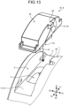
- FIG. 13 is a perspective view illustrating a preparation step of the assembling method according to the first embodiment.
- the preparation step S1 is a step of seating the middle deflector 30 on the seat surface 10 of the nut main body 1.
- the middle deflector 30 is arranged in the first vertical direction Z1 of the first housing part 5 of the nut main body 1.
- An attitude of the middle deflector 30 is set so that the seated surface 40 (not illustrated in FIG. 13 ) and the scoop-up part 33 faces the first housing part 5.
- the positioning projection 38 of the middle deflector 30 is caused to indicate the first axial direction X1.
- the middle deflector 30 according to the present embodiment includes the positioning projection 38. However, in a case in which the middle deflector 30 does not include the positioning projection 38, it should be checked whether the opening 37 faces the first axial direction X1 instead of the positioning projection 38.
- the middle deflector 30 is moved in the second vertical direction Z2 (refer to an arrow A1 in FIG. 13 ), and the middle deflector 30 is inserted into the first housing part 5.
- the position of the middle deflector 30 is adjusted in the axial direction and the seat surface direction so that the scoop-up part 33 is inserted into the through hole 17 and the positioning projection 38 is inserted into the positioning hole 26.
- the seated surface 40 of the middle deflector 30 abuts on the seat surface 10. Due to this, the middle deflector 30 is seated on the seat surface 10, and the preparation step S1 ends.
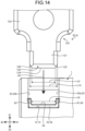
- FIG. 14 is a side view of a state before caulking viewed from the second seat surface direction at the caulking step of the assembling method according to the first embodiment.
- the caulking step S2 is a step of caulking the rib 60 with a jig 120.
- a gap amount in the axial direction between the first rib 61 and the second rib 62 is L8.
- the jig 120 includes a head part 121 inserted between the first rib 61 and the second rib 62, and a grasping part 122 arranged in the first vertical direction Z1 of the head part 121.
- a distal end part 123 is disposed at an end part in the second vertical direction Z2 of the head part 121.
- a width in the axial direction of the distal end part 123 becomes narrower toward the second vertical direction Z2.
- the distal end part 123 includes a distal end surface 124 facing the second vertical direction Z2, a first pressing surface 125 facing the first axial direction X1, and a second pressing surface 126 facing the second axial direction X2.
- a width L9 in the axial direction of the distal end surface 124 is smaller than a separation distance L8 between the first rib 61 and the second rib 62.
- a width in the axial direction between the first pressing surface 125 and the second pressing surface 126 gradually increases toward the first vertical direction Z1, and is L10 at the maximum.
- the maximum width L10 in the axial direction between the first pressing surface 125 and the second pressing surface 126 is larger than the separation distance L8 between the first rib 61 and the second rib 62.
- the distal end part 123 of the jig 120 is inserted between the first rib 61 and the second rib 62 from the first vertical direction Z1 (refer to an arrow A2 in FIG. 14 ). Due to this, although not particularly illustrated, the distal end surface 124 is inserted between the first rib 61 and the second rib 62, the first pressing surface 125 abuts on the first rib 61, and the second pressing surface 126 abuts on the second rib 62. The distal end surface 124 is caused to be in a state of floating above (being separated from) the plane 55 of the arm part 50.
- FIG. 15 is a side view of a state after caulking viewed from the second seat surface direction at the caulking step of the assembling method according to the first embodiment.
- the jig 120 is pressed in the second vertical direction Z2, and the distal end surface 124 is caused to abut on the plane 55. Due to this, the first rib 61 is caulked in the first axial direction X1 by the first pressing surface 125. Additionally, the second rib 62 is caulked in the second axial direction X2 by the second pressing surface 126.
- a caulked portion of the first rib 61 is inclined toward the first recessed part 22a arranged in the first axial direction X1, and becomes the first caulking part 71.
- the first caulking part 71 is compressed in the axial direction between an inner surface of the first recessed part 22a and the first pressing surface 125 to have a shape along the inner surface of the first recessed part 22a. That is, the first caulking part 71 includes the side surface 71a extending along the first oblique surface 23a and the end face 71b extending along the second oblique surface 24a.
- a caulked portion of the second rib 62 is inclined toward the second recessed part 22b arranged in the second axial direction X2, and becomes the second caulking part 72.
- the second caulking part 72 is compressed in the axial direction between an inner surface of the second recessed part 22b and the second pressing surface 126 to have a shape along the inner surface of the first recessed part 22a. That is, the second caulking part 72 includes the side surface 72a extending along the first oblique surface 23b and the end face 72b extending along the second oblique surface 24b.
- the jig 120 is removed in the first vertical direction Z1, and the caulking step S2 ends.
- FIG. 16 is a plan view of the caulking step according to the first embodiment viewed from the first vertical direction.
- a portion caulked by the jig 120 is not the entire rib 60 but the distal end part 60b of the rib 60. This is because the base part 60a of the rib 60 is connected to the deflector main body 31 and is hardly inclined. Furthermore, if the base part 60a of the rib 60 is forcibly caulked, the deflector main body 31 may be deformed.
- the first caulking part 71 and the second caulking part 72 form a substantially truncated chevron shape viewed from the first vertical direction Z1. That is, an inclination amount in the axial direction of the first caulking part 71 and the second caulking part 72 increases toward the distal end part 60b side. Not only the caulked distal end part 60b but also a center part in the seat surface direction of the rib 60 is slightly inclined in the axial direction.
- a load acts on the middle deflector 30, the load toward a direction in which the rib 60 escapes from a load of the jig 120 (refer to arrows A3 and A4).
- a load in the second seat surface direction Y2 acts on the middle deflector 30 (refer to the arrow A3).
- a load in the first seat surface direction Y1 acts on the middle deflector 30 (refer to the arrow A4). Accordingly, there is a possibility that the positioning projection 38 is deformed and the middle deflector 30 is displaced.
- FIG. 17 is a perspective view of a state in which caulking is performed with two jigs at the caulking step according to the first embodiment that is obliquely viewed.
- the stepped surface 87 abuts on the end face 88 (refer to FIG. 7 ).
- the caulking part 70 is hooked by the recessed part 22.
- the middle deflector 30 is not displaced in the first vertical direction Z1. That is, the middle deflector 30 is not detached from the nut main body 1.
- the base part 60a of the rib 60 is connected to the deflector main body 31, and the rib 60 and the caulking part 70 have high rigidity and are hardly inclined.
- the caulking part 70 is hardly deformed (additionally, hardly inclined). Also due to this, the middle deflector 30 is prevented from being displaced in the first vertical direction Z1.
- the caulking part 70 is disposed on each of the first arm part 51 and the second arm part 52. That is, according to the first embodiment, the number of caulking points (caulking parts 70) is larger than that in a case in which the caulking part 70 is disposed on only one of the two arm parts 50. Thus, the middle deflector 30 is firmly prevented from slipping off.
- One of the two arm parts 50 is disposed on the inner peripheral side component 81, and the other one thereof is disposed on the outer peripheral side component 82. Due to this, if joining between the inner peripheral side component 81 and the outer peripheral side component 82 is released, each of the inner peripheral side component 81 and the outer peripheral side component 82 is not detached from the nut main body 1.
- the caulking part 70 includes the first caulking part 71 and the second caulking part 72 for one arm part 50. That is, the number of caulking points (caulking parts 70) is larger than that in a case in which one caulking part 70 is disposed for one arm part 50. Thus, the middle deflector 30 is more firmly prevented from slipping off.
- the middle deflector 30 includes, as seated surfaces 40, the first seated surface 41 and the first seated surface 53 for the arm part arranged in the first seat surface direction Y with respect to the through hole 17, and the second seated surface 42 and the second seated surface 54 for the arm part arranged in the second seat surface direction Y2 with respect to the through hole 17. That is, the middle deflector 30 includes the seated surfaces 40 on both sides in the seat surface direction across the through hole 17. Accordingly, the deflector main body 31 does not fall down to the through hole 17, and the attitude of the middle deflector 30 is stable. As a result, the ball 103 is smoothly scooped up.
- the middle deflector 30 also includes the expanded seated surface 43 abutting on the expanded seat surface 13 of the seat surface 10. Accordingly, the attitude of the middle deflector 30 is further stabilized.
- the expanded seated surface 43 is disposed on the inner peripheral side component 81. Thus, if joining between the inner peripheral side component 81 and the outer peripheral side component 82 is released, the expanded seated surface 43 is hooked by the expanded seat surface 13, and the inner peripheral side component 81 is prevented from falling down to the through hole 17.
- the division surface 80 between the inner peripheral side component 81 and the outer peripheral side component 82 extends in the axial direction along the ball passage 34. If the division surface extends in a direction orthogonal to the axial direction (a plane extending in both of the seat surface direction and the vertical direction), the tongue is divided in the axial direction, and the strength of the tongue is lowered. That is, in the present embodiment, by cutting the ball passage 34 in the axial direction, the tongue 35 is caused to be part of the configuration of the inner peripheral side component 81 without being divided. Due to this, the strength of the tongue 35 is maintained.
- the ball screw device 100 includes the nut 101, the screw shaft 102 passing through the nut 101, and the balls 103 arranged between the nut 101 and the screw shaft 102.
- the nut 101 includes the nut main body 1 having a cylindrical shape through which the screw shaft 102 passes, and the circulation component (middle deflector 30) assembled to the nut main body 1.
- the nut main body 1 includes the housing part (first housing part 5), which is an indentation disposed on the outer peripheral surface 4 of the nut main body 1 and has a bow shape when viewed from the axial direction parallel with the screw shaft 102, the seat surface 10 forming the bottom surface of the housing part, the through hole 17 passing through the seat surface 10 and the inner peripheral surface 2 of the nut main body 1, and the pair of side surfaces 20 opposed to each other that are arranged on both sides in the axial direction parallel with the screw shaft 102 with respect to the housing part (first housing part 5).
- a direction parallel with the seat surface when viewed from the axial direction is the seat surface direction.
- the circulation component includes the circulation component main body (deflector main body 31) arranged in the housing part and the through hole 17, the two arm parts 50 extending toward both sides in the seat surface direction from the circulation component main body and abutting on the seat surface, the rib 60 projecting from each of the two arm parts 50 in the first vertical direction Z1 and extending in the seat surface direction along the side surface 20, and the caulking part 70 obtained by caulking at least part of the rib 60 toward the side surface.
- the recessed parts 22 that the caulking parts 70 enter are disposed on the pair of side surfaces 20, the recessed parts 22 as grooves extending in the seat surface direction and being opposed to the ribs 60 in the axial direction.
- the ball passage 34 extending in the tangential direction (virtual line K1) with respect to the raceway 106 for the ball 103 is disposed in the circulation component main body (deflector main body 31).
- the circulation component (middle deflector 30) is obtained by joining the inner peripheral side component 81 to an outer peripheral side component 82E that are divided at the division surface 80 extending along the ball passage 34 when viewed from the axial direction.
- the inner peripheral side component 81 includes the tongue 35 for scooping up the ball 103 from the raceway 106, the inner peripheral side rolling surface 85 surrounding the inner peripheral side of the ball passage 34, and one of the two arm parts 50.
- the outer peripheral side component 82 includes the outer peripheral side rolling surface 86 surrounding the outer peripheral side of the ball passage 34, and the other one of the two arm parts 50.
- the circulation component (middle deflector 30) is not detached from the nut main body 1. Additionally, a pin for fixing the circulation component (middle deflector 30) is not required, so that the number of components is prevented from being increased. If joining between the inner peripheral side component 81 and the outer peripheral side component 82 is released, each of the inner peripheral side component 81 and the outer peripheral side component 82 has the one arm part 50. Accordingly, each of the inner peripheral side component 81 and the outer peripheral side component 82 does not fall down to the through hole 17, and is not detached from the nut main body 1.
- the tongue 35 is disposed integrally with the inner peripheral side component 81 without being divided. Accordingly, the strength of the tongue 35 is maintained, and the ball 103 is smoothly scooped up.
- the pair of side surfaces 20 include the first side surface 20a arranged on one side of the axial direction with respect to the circulation component (middle deflector 30), and the second side surface 20b arranged on the other side of the axial direction with respect to the circulation component.
- the ribs 60 include the first rib 61 extending along the first side surface 20a, and the second rib 62 extending along the second side surface 20b.
- the caulking parts 70 include the first caulking part 71, which is part of the first rib 61 and caulked to the first side surface 20a, and the second caulking part 72, which is part of the second rib 62 and caulked to the second side surface 20b.
- the number of the caulking points (caulking parts 70) is large, so that the middle deflector 30 is more firmly prevented from slipping off.
- the nut main body 1 includes the positioning hole 26, which is recessed in the axial direction from the side surface 20 and opens to the outer peripheral surface 4 of the nut main body 1.
- the circulation component main body deflector main body 31
- the positioning projection 38 projecting in the axial direction to be inserted into the positioning hole 26.
- displacement of the middle deflector 30 in the seat surface direction is regulated.
- the tongue 35 is arranged at a predetermined position, and the ball 103 is smoothly scooped up.
- the seat surface 10 includes the expanded seat surface 13, which is the edge 17a of the through hole 17, and arranged on both sides in the axial direction with respect to the through hole 17.
- the inner peripheral side component 81 includes the expanded seated surface 43 abutting on the expanded seat surface 13.
- the number of portions abutting on the seat surface 10 increases, and the attitude of the middle deflector 30 is further stabilized. Additionally, the inner peripheral side component 81 can be prevented from falling down to the through hole 17.
- the ball screw device 100 according to the first embodiment has been described above.
- the following describes other embodiments in which the nut in the first embodiment is partially deformed.
- a minute gap (not illustrated) is generated between the first side surface 20a and the first opposing surface 36, or between the second side surface 20b and the second opposing surface 46, or between both of them. If the gap between the first side surface 20a and the first opposing surface 36 is large, the opening 37 of the ball passage 34 is separated from the opening 8a of the return path 8, and the ball 103 cannot be smoothly delivered.
- the following describes a second embodiment to a fourth embodiment in which the above point is improved. The following focuses on changes from the first embodiment.
- FIG. 18 is a side view of the nut according to the second embodiment in a state before the rib is caulked thereto viewed from the second seat surface direction.
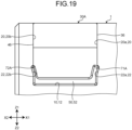
- FIG. 19 is a side view of the nut according to the second embodiment in a state after the rib is caulked thereto viewed from the second seat surface direction.
- a middle deflector 30A according to the second embodiment is different from the middle deflector 30 according to the first embodiment in that the middle deflector 30A includes a first rib 61A and a second rib 62A having different thicknesses in the axial direction.
- FIG. 18 illustrates only the rib of the second arm part, but the first rib 61A and the second rib 62A are also disposed on the first arm part 51.
- a thickness L12 in the axial direction of the second rib 62A is smaller than a thickness L11 in the axial direction of the first rib 61A.
- a first caulking part 71A is generated as illustrated in FIG. 19 .
- a second caulking part 72A is generated.
- the second rib 62A having a smaller thickness in the axial direction and having lower rigidity starts to be inclined (starts to be deformed) earlier than the first rib 61A.
- a caulked portion (the second caulking part 72A) of the second rib 62A abuts on an inner surface of the recessed part 22 earlier than a caulked portion (the first caulking part 71A) of the first rib 61A, and presses the inner surface of the recessed part 22. Due to this, reaction force (refer to an arrow A5) against pressing force of the second caulking part 72A acts on the middle deflector 30A. The middle deflector 30A then moves in the first axial direction X1, and the first opposing surface 36 abuts on the first side surface 20a.
- the opening 37 of the ball passage 34 continues (is adjacent) to the opening 8a of the return path 8, and the ball 103 can be smoothly delivered.
- FIG. 20 is a side view of the nut according to the third embodiment in a state before the rib is caulked thereto viewed from the second seat surface direction.
- FIG. 21 is a side view of the nut according to the third embodiment in a state after the rib is caulked thereto viewed from the second seat surface direction.
- a middle deflector 30B according to the third embodiment is different from the middle deflector 30 according to the first embodiment in that the middle deflector 30B includes a first rib 61B and a second rib 62B in place of the first rib 61 and the second rib 62.
- the first rib 61B includes a first caulking surface 61a facing the second axial direction X2.
- the second rib 62B includes a second caulking surface 62a facing the first axial direction X1.
- the first caulking surface 61a and the second caulking surface 62a are opposed to each other.
- the first caulking surface 61a is an inclined surface that is inclined to be closer to the first side surface 20a (in the first axial direction X1) toward the first vertical direction Z1.
- the first caulking surface 61a When the first caulking surface 61a is caulked with the jig 120, part of a caulking load (a load in the first axial direction X1) acting on the first caulking surface 61a is converted into a load in the second vertical direction Z2. That is, the load in the first axial direction X1 acting on the first rib 61B is reduced.
- a base part side of the first rib 61B (a portion close to the arm part 50) has a large thickness in the axial direction, and has high rigidity. Due to this, the first rib B is hardly deformed as compared with the second rib 62B.
- the first rib 61B is inclined later than the second rib 62B. Accordingly, a caulked portion (a second caulking part 72B) of the second rib 62B abuts on the inner surface of the recessed part 22 earlier than the first rib 61B, and further presses the inner surface of the recessed part 22.
- the second caulking part 72B receives reaction force (refer to an arrow A7) from the inner surface of the recessed part 22, the middle deflector 30B moves in the first axial direction X1, and the first opposing surface 36 abuts on the first side surface 20a.
- the opening 37 of the ball passage 34 continues (is adjacent) to the opening 8a of the return path 8, and the ball 103 can be smoothly delivered.
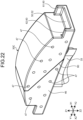
- FIG. 22 is a perspective view of the middle deflector according to the fourth embodiment viewed from the second axial direction.
- FIG. 23 is an enlarged view of the gap between the second side surface and the second opposing surface of the nut according to the fourth embodiment viewed from the first vertical direction.
- a middle deflector 30C according to the fourth embodiment is different from the middle deflector 30 according to the first embodiment in that a plurality of projecting parts 47 are disposed on the second opposing surface 46.
- the projecting part 47 is a projection that is formed integrally with the middle deflector 30C.
- the projecting part 47 has a hemispherical shape.
- a cross section of the projecting part 47 cut along a plane extending in the seat surface direction and the vertical direction has a circular shape.
- a projecting amount in the axial direction of the projecting part 47 is larger than a minute gap (tolerance) in the axial direction generated between the first housing part 5 and the middle deflector 30C.
- the middle deflector 30C according to the fourth embodiment when the middle deflector 30C according to the fourth embodiment is inserted into the first housing part 5, the projecting part 47 is pressed against the second side surface 20b, and a distal end part of the projecting part 47 is crushed. Due to this, the middle deflector 30C is pressed in the first axial direction X1 (refer to an arrow A8 in FIG. 23 ), and the first opposing surface 36 abuts on the first side surface 20a. As described above, also according to the fourth embodiment, the opening 37 of the ball passage 34 continues (is adjacent) to the opening 8a of the return path 8, and the ball 103 can be smoothly delivered.
- a plurality of the projecting parts 47 are provided in the present embodiment, but it is sufficient that at least one projecting part 47 is provided according to the present invention.
- the shape of the projecting part 47 is not limited to the hemispherical shape, but may be a cylinder, a rectangular column, a cone, and a frustum.
- the shape is not particularly limited.
- the second embodiment to the fourth embodiment have been described above, but pieces of technical content of the second embodiment to the fourth embodiment may be combined with each other in the present invention. That is, all of the second embodiment to the fourth embodiment may be applied to the present disclosure. Alternatively, two of the second embodiment to the fourth embodiment may be selected to be applied.
- FIG. 24 is a perspective view of the middle deflector according to the fifth embodiment that is obliquely viewed.
- a middle deflector 30D according to the fifth embodiment is different from the middle deflector 30 according to the first embodiment in that a length in the seat surface direction of an arm part 50D is longer than a length in the seat surface direction of the rib 60. That is, a distal end part 50a of the arm part 50D according to the fifth embodiment projects toward an outer side in the seat surface direction than the distal end part 60b of the rib 60.
- the middle deflector 30D an area abutting on the seat surface 10 is increased, and an attitude of the middle deflector 30D is further stabilized.
- the middle deflector 30D according to the fifth embodiment is different from the middle deflector 30 according to the first embodiment in that positioning projections 38 are disposed on both of the first opposing surface 36 and the second opposing surface 46 (not illustrated in FIG. 24 , refer to FIG. 11 and FIG. 12 ).
- positioning holes 26 are each disposed on the first side surface 20a and the second side surface 20b of the nut main body 1. Due to this, positioning in the seat surface direction by the middle deflector 30D can be strengthened.
- the present invention does not necessarily include the expanded seated surface 43 (refer to FIG. 9 ) like the middle deflector 30D according to the fifth embodiment.
- the positioning projections 38 are disposed on both of the first opposing surface 36 and the second opposing surface 46, so that there is a possibility that the middle deflector 30 may be arranged in the first housing part 5 in an erroneous orientation.
- a sign indicating an assembling direction of the deflector main body (circulation component main body) 31 with respect to the first housing part (housing part) 5 is preferably attached to an outer peripheral surface of the deflector main body (circulation component main body) 31.
- FIG. 25 is a side view of the middle deflector according to the sixth embodiment viewed from the first axial direction.
- FIG. 26 is a cross-sectional view of the middle deflector according to the sixth embodiment cut along a plane extending in the seat surface direction and the vertical direction.
- a middle deflector 30E according to the sixth embodiment is different from the middle deflector 30 according to the first embodiment in that the middle deflector 30E includes an inner peripheral side component 81E and an outer peripheral side component 82E in place of the inner peripheral side component 81 and the outer peripheral side component 82.
- a division surface 90 between the inner peripheral side component 81E and the outer peripheral side component 82E includes, when viewed from the axial direction, an oblique surface 91 extending along the ball passage 34, a lateral surface 92 extending in the first seat surface direction Y1 from an end part on a radially outer side of both end parts of the oblique surface 91, and a vertical surface 93 extending in the second vertical direction Z2 from the first seat surface direction Y1 of the lateral surface 92.
- An engagement part 94 is disposed on the vertical surface 93.
- an inner peripheral side division surface 83E of the inner peripheral side component 81E a portion positioned on the oblique surface 91 is referred to as an inner peripheral side oblique surface 91a
- a portion positioned on the lateral surface 92 is referred to as an inner peripheral side lateral surface 92a
- a portion positioned on the vertical surface 93 is referred to as an inner peripheral side vertical surface 93a.
- an outer peripheral side division surface 84E of the outer peripheral side component 82E a portion positioned on the oblique surface 91 is referred to as an outer peripheral side oblique surface 91b, a portion positioned on the lateral surface 92 is referred to as an outer peripheral side lateral surface 92b, and a portion positioned on the vertical surface 93 is referred to as an outer peripheral side vertical surface 93b.
- the oblique surface 91 is inclined to be positioned in the first seat surface direction Y1 toward the first vertical direction Z1.
- the oblique surface 91 overlaps with a center part of the ball passage 34 when viewed from the axial direction.
- the inner peripheral side rolling surface 85 having a C-shape opening in the first vertical direction Z1 is disposed on the inner peripheral side oblique surface 91a of the inner peripheral side component 81E.
- the outer peripheral side rolling surface 86 having a C-shape opening in the second vertical direction Z2 is disposed on the outer peripheral side oblique surface 91b of the outer peripheral side component 82E.
- groove surfaces (the inner peripheral side rolling surface 85 and the outer peripheral side rolling surface 86) are disposed on the inner peripheral side division surface 83E and the outer peripheral side division surface 84E, respectively.
- the ball 103 rolls in the ball passage 34 smoothly as compared with the first embodiment.
- the lateral surface 92 is parallel with the seat surface 10.
- the vertical surface 93 is parallel with the vertical direction.
- the engagement part 94 includes a projection 95 and a groove part 96.
- the projection 95 projects from the inner peripheral side vertical surface 93a in the first seat surface direction Y1.
- the groove part 96 is recessed from the outer peripheral side vertical surface 93b in the first seat surface direction Y1.
- Each of the projection 95 and the groove part 96 extends in the axial direction.
- the projection 95 is inserted, from the axial direction, into the groove part 96 to be engaged therewith.
- the inner peripheral side component 81E includes the tongue 35 and the inner peripheral side rolling surface 85.
- the outer peripheral side component 82E includes the outer peripheral side rolling surface 86 and the two arm parts 50.
- the middle deflector (circulation component) 30E of the middle deflector 30E is obtained by joining the inner peripheral side component 81E to the outer peripheral side component 82E that are divided at the division surface 90 extending along the ball passage 34 when viewed from the axial direction.
- the inner peripheral side component 81E includes the tongue 35 for scooping up the ball 103 from the raceway 106, the inner peripheral side rolling surface 85 surrounding the inner peripheral side of the ball passage 34, and the inner peripheral side division surface 83E extending along the division surface.
- the outer peripheral side component 82E includes the outer peripheral side rolling surface 86 surrounding the outer peripheral side of the ball passage 34, the two arm parts 50, and the outer peripheral side division surface 84E extending along the division surface 90.
- the projection 95 projecting in the seat surface direction and extending in the axial direction.
- the groove part 96 that is recessed in the seat surface direction and extends in the axial direction, the groove part 96 with which the projection 95 is engaged.
- the middle deflector 30E includes the caulking part (not illustrated in FIG. 25 and FIG. 26 ) similarly to the first embodiment, and is not displaced in the first vertical direction Z1. If joining between the inner peripheral side component 81E and the outer peripheral side component 82E is released, the outer peripheral side component 82E includes the two arm parts 50, so that the outer peripheral side component 82E is not displaced in the vertical direction. On the other hand, the inner peripheral side component 81E does not include the arm part 50, but the projection 95 is hooked by the groove part 96, so that the inner peripheral side component 81E is not displaced in the second vertical direction Z2. That is, the inner peripheral side component 81E is prevented from falling down to the through hole 17.
- the tongue 35 is disposed integrally with the inner peripheral side component 81E without being divided. Accordingly, the strength of the tongue 35 is maintained, and the ball 103 is smoothly scooped up.
- the inner peripheral side component 81E When joining between the inner peripheral side component 81E and the outer peripheral side component 82E is released, and the inner peripheral side component 81E slides in the axial direction, the inner peripheral side component 81E is brought into contact with the edge 17a (refer to FIG. 4 ) of the through hole 17. Thus, it is possible to avoid a situation in which the projection 95 slides in the axial direction, and engagement with the groove part 96 is released.
- the outer peripheral side oblique surface 91b is arranged in the second seat surface direction Y2 of the groove part 96. Thus, movement of the inner peripheral side component 81E in the second seat surface direction Y2 is regulated.
- the present invention is not limited to the middle deflector 30 and the first housing part 5 (seat surface 10) extending in a direction orthogonal to the axis O (refer to FIG. 4 ) when viewed from the outer peripheral side.
- the middle deflector 30 and the first housing part 5 (seat surface 10) may extend in a direction parallel with the raceway 106. That is, the middle deflector 30 and the first housing part 5 (seat surface 10) may be inclined in a direction other than the direction orthogonal to the axis O when viewed from the outer peripheral side, and the direction is not particularly limited.
- the through hole 17 may be inclined in the same direction as the seat surface 10.
- the caulking parts 70 are disposed on both sides in the axial direction of the arm part 50, but the caulking part 70 may be disposed only on one side in the axial direction of the arm part 50 in the present invention.
- the caulking parts 70 are disposed on both of the first arm part 51 and the second arm part 52, but the caulking part 70 may be disposed only on one of the first arm part 51 and the second arm part 52.
- the outer peripheral surface 32a of the middle deflector 30 has a circular arc shape, but the outer peripheral surface 32a of the middle deflector 30 does not necessarily have a circular arc shape in the present invention.
- a distance between the axis O and the outer peripheral surface 32a of the middle deflector 30 may be smaller than an outer diameter of the nut main body 1.
- the expanded seat surface 13 includes the first expanded seat surface 14 and the second expanded seat surface 15, but the expanded seat surface 13 may be constituted of the first expanded seat surface 14 or the second expanded seat surface 15 in the present invention.
Landscapes
- Engineering & Computer Science (AREA)
- General Engineering & Computer Science (AREA)
- Mechanical Engineering (AREA)
- Transmission Devices (AREA)
Applications Claiming Priority (2)
| Application Number | Priority Date | Filing Date | Title |
|---|---|---|---|
| JP2022010680 | 2022-01-27 | ||
| PCT/JP2022/038134 WO2023145147A1 (ja) | 2022-01-27 | 2022-10-13 | ナット及びボールねじ装置 |
Publications (3)
| Publication Number | Publication Date |
|---|---|
| EP4242490A1 EP4242490A1 (en) | 2023-09-13 |
| EP4242490A4 EP4242490A4 (en) | 2023-11-08 |
| EP4242490B1 true EP4242490B1 (en) | 2024-11-06 |
Family
ID=87201344
Family Applications (1)
| Application Number | Title | Priority Date | Filing Date |
|---|---|---|---|
| EP22879575.3A Active EP4242490B1 (en) | 2022-01-27 | 2022-10-13 | Nut and ball screw device comprising the same |
Country Status (4)
| Country | Link |
|---|---|
| US (1) | US11808328B2 (https=) |
| EP (1) | EP4242490B1 (https=) |
| JP (1) | JP7311074B1 (https=) |
| CN (1) | CN116829851A (https=) |
Families Citing this family (1)
| Publication number | Priority date | Publication date | Assignee | Title |
|---|---|---|---|---|
| EP4317747A4 (en) * | 2022-01-27 | 2025-01-15 | NSK Ltd. | NUT AND BALL SCREW DEVICE |
Family Cites Families (4)
| Publication number | Priority date | Publication date | Assignee | Title |
|---|---|---|---|---|
| JP6511463B2 (ja) | 2014-10-01 | 2019-05-15 | 黒田精工株式会社 | ボールねじ機構のデフレクタ及びボールねじ機構 |
| JP6915004B2 (ja) * | 2019-08-27 | 2021-08-04 | 日本ピストンリング株式会社 | ボール循環部品 |
| CN114364902B (zh) * | 2020-04-13 | 2025-10-10 | 日本精工株式会社 | 滚珠丝杠装置 |
| JP7439648B2 (ja) * | 2020-05-29 | 2024-02-28 | 日本精工株式会社 | ボールねじ装置 |
-
2022
- 2022-10-13 JP JP2023518389A patent/JP7311074B1/ja active Active
- 2022-10-13 EP EP22879575.3A patent/EP4242490B1/en active Active
- 2022-10-13 CN CN202280006878.9A patent/CN116829851A/zh active Pending
- 2022-10-13 US US18/031,926 patent/US11808328B2/en active Active
Also Published As
| Publication number | Publication date |
|---|---|
| JP7311074B1 (ja) | 2023-07-19 |
| JPWO2023145147A1 (https=) | 2023-08-03 |
| US20230287967A1 (en) | 2023-09-14 |
| EP4242490A4 (en) | 2023-11-08 |
| US11808328B2 (en) | 2023-11-07 |
| CN116829851A (zh) | 2023-09-29 |
| EP4242490A1 (en) | 2023-09-13 |
Similar Documents
| Publication | Publication Date | Title |
|---|---|---|
| US6955476B1 (en) | Retainer for rolling bearings | |
| JP4970883B2 (ja) | ワンウエイ・クラッチ | |
| US20070196189A1 (en) | Ball screw device and method of manufacturing the same | |
| US11300166B2 (en) | Reverse input blocking clutch | |
| EP4242490B1 (en) | Nut and ball screw device comprising the same | |
| JPH01238714A (ja) | 直線運動用ボールベアリング | |
| JP7439648B2 (ja) | ボールねじ装置 | |
| US20150167740A1 (en) | Single-split cage | |
| US5743720A (en) | Scroll compressor with axial biasing | |
| JP2023170328A (ja) | ナット及びボールねじ装置 | |
| CN110799765B (zh) | 径向箔轴承 | |
| EP4317747A1 (en) | Nut and ball screw device | |
| KR100465543B1 (ko) | 스크롤압축기 | |
| JP7800298B2 (ja) | ナット及びボールねじ装置 | |
| CN109072906B (zh) | 涡旋流体机械及涡旋部件的加工方法 | |
| WO2019130385A1 (ja) | ボールねじ | |
| EP4086478B1 (en) | Ball screw device | |
| EP3889466B1 (en) | Ball screw device | |
| WO2023145147A1 (ja) | ナット及びボールねじ装置 | |
| CN106795918A (zh) | 轴承装置和轴承装置的制造方法 | |
| EP4513059A1 (en) | Ball screw device | |
| JPWO2001058745A1 (ja) | 履帯のリンクとピンとの固定構造 | |
| JP2817284B2 (ja) | スクロール型圧縮機 | |
| CN121382871A (zh) | 滚珠丝杠的循环部件 | |
| JP2025074838A (ja) | ボールねじ装置 |
Legal Events
| Date | Code | Title | Description |
|---|---|---|---|
| STAA | Information on the status of an ep patent application or granted ep patent |
Free format text: STATUS: UNKNOWN |
|
| STAA | Information on the status of an ep patent application or granted ep patent |
Free format text: STATUS: THE INTERNATIONAL PUBLICATION HAS BEEN MADE |
|
| PUAI | Public reference made under article 153(3) epc to a published international application that has entered the european phase |
Free format text: ORIGINAL CODE: 0009012 |
|
| STAA | Information on the status of an ep patent application or granted ep patent |
Free format text: STATUS: REQUEST FOR EXAMINATION WAS MADE |
|
| 17P | Request for examination filed |
Effective date: 20230419 |
|
| AK | Designated contracting states |
Kind code of ref document: A1 Designated state(s): AL AT BE BG CH CY CZ DE DK EE ES FI FR GB GR HR HU IE IS IT LI LT LU LV MC ME MK MT NL NO PL PT RO RS SE SI SK SM TR |
|
| A4 | Supplementary search report drawn up and despatched |
Effective date: 20231010 |
|
| RIC1 | Information provided on ipc code assigned before grant |
Ipc: F16H 25/22 20060101ALI20231004BHEP Ipc: F16H 25/24 20060101AFI20231004BHEP |
|
| GRAP | Despatch of communication of intention to grant a patent |
Free format text: ORIGINAL CODE: EPIDOSNIGR1 |
|
| STAA | Information on the status of an ep patent application or granted ep patent |
Free format text: STATUS: GRANT OF PATENT IS INTENDED |
|
| INTG | Intention to grant announced |
Effective date: 20240604 |
|
| GRAS | Grant fee paid |
Free format text: ORIGINAL CODE: EPIDOSNIGR3 |
|
| GRAA | (expected) grant |
Free format text: ORIGINAL CODE: 0009210 |
|
| STAA | Information on the status of an ep patent application or granted ep patent |
Free format text: STATUS: THE PATENT HAS BEEN GRANTED |
|
| AK | Designated contracting states |
Kind code of ref document: B1 Designated state(s): AL AT BE BG CH CY CZ DE DK EE ES FI FR GB GR HR HU IE IS IT LI LT LU LV MC ME MK MT NL NO PL PT RO RS SE SI SK SM TR |
|
| DAV | Request for validation of the european patent (deleted) | ||
| DAX | Request for extension of the european patent (deleted) | ||
| REG | Reference to a national code |
Ref country code: GB Ref legal event code: FG4D |
|
| REG | Reference to a national code |
Ref country code: CH Ref legal event code: EP |
|
| REG | Reference to a national code |
Ref country code: DE Ref legal event code: R096 Ref document number: 602022007575 Country of ref document: DE |
|
| REG | Reference to a national code |
Ref country code: IE Ref legal event code: FG4D |
|
| REG | Reference to a national code |
Ref country code: LT Ref legal event code: MG9D |
|
| REG | Reference to a national code |
Ref country code: NL Ref legal event code: MP Effective date: 20241106 |
|
| PG25 | Lapsed in a contracting state [announced via postgrant information from national office to epo] |
Ref country code: PT Free format text: LAPSE BECAUSE OF FAILURE TO SUBMIT A TRANSLATION OF THE DESCRIPTION OR TO PAY THE FEE WITHIN THE PRESCRIBED TIME-LIMIT Effective date: 20250306 Ref country code: HR Free format text: LAPSE BECAUSE OF FAILURE TO SUBMIT A TRANSLATION OF THE DESCRIPTION OR TO PAY THE FEE WITHIN THE PRESCRIBED TIME-LIMIT Effective date: 20241106 Ref country code: IS Free format text: LAPSE BECAUSE OF FAILURE TO SUBMIT A TRANSLATION OF THE DESCRIPTION OR TO PAY THE FEE WITHIN THE PRESCRIBED TIME-LIMIT Effective date: 20250306 |
|
| PG25 | Lapsed in a contracting state [announced via postgrant information from national office to epo] |
Ref country code: FI Free format text: LAPSE BECAUSE OF FAILURE TO SUBMIT A TRANSLATION OF THE DESCRIPTION OR TO PAY THE FEE WITHIN THE PRESCRIBED TIME-LIMIT Effective date: 20241106 Ref country code: NL Free format text: LAPSE BECAUSE OF FAILURE TO SUBMIT A TRANSLATION OF THE DESCRIPTION OR TO PAY THE FEE WITHIN THE PRESCRIBED TIME-LIMIT Effective date: 20241106 |
|
| REG | Reference to a national code |
Ref country code: AT Ref legal event code: MK05 Ref document number: 1739647 Country of ref document: AT Kind code of ref document: T Effective date: 20241106 |
|
| PG25 | Lapsed in a contracting state [announced via postgrant information from national office to epo] |
Ref country code: BG Free format text: LAPSE BECAUSE OF FAILURE TO SUBMIT A TRANSLATION OF THE DESCRIPTION OR TO PAY THE FEE WITHIN THE PRESCRIBED TIME-LIMIT Effective date: 20241106 |
|
| PG25 | Lapsed in a contracting state [announced via postgrant information from national office to epo] |
Ref country code: ES Free format text: LAPSE BECAUSE OF FAILURE TO SUBMIT A TRANSLATION OF THE DESCRIPTION OR TO PAY THE FEE WITHIN THE PRESCRIBED TIME-LIMIT Effective date: 20241106 |
|
| PG25 | Lapsed in a contracting state [announced via postgrant information from national office to epo] |
Ref country code: NO Free format text: LAPSE BECAUSE OF FAILURE TO SUBMIT A TRANSLATION OF THE DESCRIPTION OR TO PAY THE FEE WITHIN THE PRESCRIBED TIME-LIMIT Effective date: 20250206 |
|
| PG25 | Lapsed in a contracting state [announced via postgrant information from national office to epo] |
Ref country code: GR Free format text: LAPSE BECAUSE OF FAILURE TO SUBMIT A TRANSLATION OF THE DESCRIPTION OR TO PAY THE FEE WITHIN THE PRESCRIBED TIME-LIMIT Effective date: 20250207 Ref country code: LV Free format text: LAPSE BECAUSE OF FAILURE TO SUBMIT A TRANSLATION OF THE DESCRIPTION OR TO PAY THE FEE WITHIN THE PRESCRIBED TIME-LIMIT Effective date: 20241106 Ref country code: AT Free format text: LAPSE BECAUSE OF FAILURE TO SUBMIT A TRANSLATION OF THE DESCRIPTION OR TO PAY THE FEE WITHIN THE PRESCRIBED TIME-LIMIT Effective date: 20241106 |
|
| PG25 | Lapsed in a contracting state [announced via postgrant information from national office to epo] |
Ref country code: PL Free format text: LAPSE BECAUSE OF FAILURE TO SUBMIT A TRANSLATION OF THE DESCRIPTION OR TO PAY THE FEE WITHIN THE PRESCRIBED TIME-LIMIT Effective date: 20241106 |
|
| PG25 | Lapsed in a contracting state [announced via postgrant information from national office to epo] |
Ref country code: RS Free format text: LAPSE BECAUSE OF FAILURE TO SUBMIT A TRANSLATION OF THE DESCRIPTION OR TO PAY THE FEE WITHIN THE PRESCRIBED TIME-LIMIT Effective date: 20250206 |
|
| PG25 | Lapsed in a contracting state [announced via postgrant information from national office to epo] |
Ref country code: SM Free format text: LAPSE BECAUSE OF FAILURE TO SUBMIT A TRANSLATION OF THE DESCRIPTION OR TO PAY THE FEE WITHIN THE PRESCRIBED TIME-LIMIT Effective date: 20241106 |
|
| PG25 | Lapsed in a contracting state [announced via postgrant information from national office to epo] |
Ref country code: DK Free format text: LAPSE BECAUSE OF FAILURE TO SUBMIT A TRANSLATION OF THE DESCRIPTION OR TO PAY THE FEE WITHIN THE PRESCRIBED TIME-LIMIT Effective date: 20241106 |
|
| PG25 | Lapsed in a contracting state [announced via postgrant information from national office to epo] |
Ref country code: EE Free format text: LAPSE BECAUSE OF FAILURE TO SUBMIT A TRANSLATION OF THE DESCRIPTION OR TO PAY THE FEE WITHIN THE PRESCRIBED TIME-LIMIT Effective date: 20241106 |
|
| PG25 | Lapsed in a contracting state [announced via postgrant information from national office to epo] |
Ref country code: RO Free format text: LAPSE BECAUSE OF FAILURE TO SUBMIT A TRANSLATION OF THE DESCRIPTION OR TO PAY THE FEE WITHIN THE PRESCRIBED TIME-LIMIT Effective date: 20241106 |
|
| PG25 | Lapsed in a contracting state [announced via postgrant information from national office to epo] |
Ref country code: SK Free format text: LAPSE BECAUSE OF FAILURE TO SUBMIT A TRANSLATION OF THE DESCRIPTION OR TO PAY THE FEE WITHIN THE PRESCRIBED TIME-LIMIT Effective date: 20241106 |
|
| PG25 | Lapsed in a contracting state [announced via postgrant information from national office to epo] |
Ref country code: CZ Free format text: LAPSE BECAUSE OF FAILURE TO SUBMIT A TRANSLATION OF THE DESCRIPTION OR TO PAY THE FEE WITHIN THE PRESCRIBED TIME-LIMIT Effective date: 20241106 |
|
| PG25 | Lapsed in a contracting state [announced via postgrant information from national office to epo] |
Ref country code: IT Free format text: LAPSE BECAUSE OF FAILURE TO SUBMIT A TRANSLATION OF THE DESCRIPTION OR TO PAY THE FEE WITHIN THE PRESCRIBED TIME-LIMIT Effective date: 20241106 |
|
| REG | Reference to a national code |
Ref country code: DE Ref legal event code: R097 Ref document number: 602022007575 Country of ref document: DE |
|
| PG25 | Lapsed in a contracting state [announced via postgrant information from national office to epo] |
Ref country code: SE Free format text: LAPSE BECAUSE OF FAILURE TO SUBMIT A TRANSLATION OF THE DESCRIPTION OR TO PAY THE FEE WITHIN THE PRESCRIBED TIME-LIMIT Effective date: 20241106 |
|
| PLBE | No opposition filed within time limit |
Free format text: ORIGINAL CODE: 0009261 |
|
| STAA | Information on the status of an ep patent application or granted ep patent |
Free format text: STATUS: NO OPPOSITION FILED WITHIN TIME LIMIT |
|
| 26N | No opposition filed |
Effective date: 20250807 |
|
| PGFP | Annual fee paid to national office [announced via postgrant information from national office to epo] |
Ref country code: DE Payment date: 20250902 Year of fee payment: 4 |