EP4242433A1 - Engine and flywheel housing - Google Patents
Engine and flywheel housing Download PDFInfo
- Publication number
- EP4242433A1 EP4242433A1 EP23159655.2A EP23159655A EP4242433A1 EP 4242433 A1 EP4242433 A1 EP 4242433A1 EP 23159655 A EP23159655 A EP 23159655A EP 4242433 A1 EP4242433 A1 EP 4242433A1
- Authority
- EP
- European Patent Office
- Prior art keywords
- gas
- blow
- engine
- cylinder
- cylinder block
- Prior art date
- Legal status (The legal status is an assumption and is not a legal conclusion. Google has not performed a legal analysis and makes no representation as to the accuracy of the status listed.)
- Pending
Links
- 238000002485 combustion reaction Methods 0.000 claims abstract description 14
- 238000005516 engineering process Methods 0.000 abstract description 4
- 239000007789 gas Substances 0.000 description 91
- 239000000446 fuel Substances 0.000 description 21
- 239000000498 cooling water Substances 0.000 description 4
- 238000010586 diagram Methods 0.000 description 4
- 238000002347 injection Methods 0.000 description 2
- 239000007924 injection Substances 0.000 description 2
- 239000000314 lubricant Substances 0.000 description 2
- 239000003595 mist Substances 0.000 description 2
- 239000000567 combustion gas Substances 0.000 description 1
- 238000004891 communication Methods 0.000 description 1
- 230000006835 compression Effects 0.000 description 1
- 238000007906 compression Methods 0.000 description 1
- 238000009833 condensation Methods 0.000 description 1
- 230000005494 condensation Effects 0.000 description 1
- 238000007599 discharging Methods 0.000 description 1
- 230000000694 effects Effects 0.000 description 1
- 238000003780 insertion Methods 0.000 description 1
- 230000037431 insertion Effects 0.000 description 1
- 238000005259 measurement Methods 0.000 description 1
- 239000000203 mixture Substances 0.000 description 1
- 239000000243 solution Substances 0.000 description 1
- XLYOFNOQVPJJNP-UHFFFAOYSA-N water Substances O XLYOFNOQVPJJNP-UHFFFAOYSA-N 0.000 description 1
Images


Classifications
-
- F—MECHANICAL ENGINEERING; LIGHTING; HEATING; WEAPONS; BLASTING
- F02—COMBUSTION ENGINES; HOT-GAS OR COMBUSTION-PRODUCT ENGINE PLANTS
- F02F—CYLINDERS, PISTONS OR CASINGS, FOR COMBUSTION ENGINES; ARRANGEMENTS OF SEALINGS IN COMBUSTION ENGINES
- F02F1/00—Cylinders; Cylinder heads
- F02F1/18—Other cylinders
-
- F—MECHANICAL ENGINEERING; LIGHTING; HEATING; WEAPONS; BLASTING
- F01—MACHINES OR ENGINES IN GENERAL; ENGINE PLANTS IN GENERAL; STEAM ENGINES
- F01M—LUBRICATING OF MACHINES OR ENGINES IN GENERAL; LUBRICATING INTERNAL COMBUSTION ENGINES; CRANKCASE VENTILATING
- F01M13/00—Crankcase ventilating or breathing
-
- F—MECHANICAL ENGINEERING; LIGHTING; HEATING; WEAPONS; BLASTING
- F02—COMBUSTION ENGINES; HOT-GAS OR COMBUSTION-PRODUCT ENGINE PLANTS
- F02F—CYLINDERS, PISTONS OR CASINGS, FOR COMBUSTION ENGINES; ARRANGEMENTS OF SEALINGS IN COMBUSTION ENGINES
- F02F7/00—Casings, e.g. crankcases or frames
- F02F7/0002—Cylinder arrangements
- F02F7/0012—Crankcases of V-engines
-
- B—PERFORMING OPERATIONS; TRANSPORTING
- B63—SHIPS OR OTHER WATERBORNE VESSELS; RELATED EQUIPMENT
- B63H—MARINE PROPULSION OR STEERING
- B63H21/00—Use of propulsion power plant or units on vessels
- B63H21/38—Apparatus or methods specially adapted for use on marine vessels, for handling power plant or unit liquids, e.g. lubricants, coolants, fuels or the like
-
- F—MECHANICAL ENGINEERING; LIGHTING; HEATING; WEAPONS; BLASTING
- F01—MACHINES OR ENGINES IN GENERAL; ENGINE PLANTS IN GENERAL; STEAM ENGINES
- F01M—LUBRICATING OF MACHINES OR ENGINES IN GENERAL; LUBRICATING INTERNAL COMBUSTION ENGINES; CRANKCASE VENTILATING
- F01M13/00—Crankcase ventilating or breathing
- F01M13/04—Crankcase ventilating or breathing having means for purifying air before leaving crankcase, e.g. removing oil
- F01M13/0405—Crankcase ventilating or breathing having means for purifying air before leaving crankcase, e.g. removing oil arranged in covering members apertures, e.g. caps
-
- F—MECHANICAL ENGINEERING; LIGHTING; HEATING; WEAPONS; BLASTING
- F02—COMBUSTION ENGINES; HOT-GAS OR COMBUSTION-PRODUCT ENGINE PLANTS
- F02B—INTERNAL-COMBUSTION PISTON ENGINES; COMBUSTION ENGINES IN GENERAL
- F02B75/00—Other engines
- F02B75/16—Engines characterised by number of cylinders, e.g. single-cylinder engines
- F02B75/18—Multi-cylinder engines
- F02B75/22—Multi-cylinder engines with cylinders in V, fan, or star arrangement
-
- F—MECHANICAL ENGINEERING; LIGHTING; HEATING; WEAPONS; BLASTING
- F02—COMBUSTION ENGINES; HOT-GAS OR COMBUSTION-PRODUCT ENGINE PLANTS
- F02M—SUPPLYING COMBUSTION ENGINES IN GENERAL WITH COMBUSTIBLE MIXTURES OR CONSTITUENTS THEREOF
- F02M25/00—Engine-pertinent apparatus for adding non-fuel substances or small quantities of secondary fuel to combustion-air, main fuel or fuel-air mixture
- F02M25/06—Engine-pertinent apparatus for adding non-fuel substances or small quantities of secondary fuel to combustion-air, main fuel or fuel-air mixture adding lubricant vapours
-
- F—MECHANICAL ENGINEERING; LIGHTING; HEATING; WEAPONS; BLASTING
- F02—COMBUSTION ENGINES; HOT-GAS OR COMBUSTION-PRODUCT ENGINE PLANTS
- F02N—STARTING OF COMBUSTION ENGINES; STARTING AIDS FOR SUCH ENGINES, NOT OTHERWISE PROVIDED FOR
- F02N5/00—Starting apparatus having mechanical power storage
- F02N5/04—Starting apparatus having mechanical power storage of inertia type
-
- F—MECHANICAL ENGINEERING; LIGHTING; HEATING; WEAPONS; BLASTING
- F16—ENGINEERING ELEMENTS AND UNITS; GENERAL MEASURES FOR PRODUCING AND MAINTAINING EFFECTIVE FUNCTIONING OF MACHINES OR INSTALLATIONS; THERMAL INSULATION IN GENERAL
- F16M—FRAMES, CASINGS OR BEDS OF ENGINES, MACHINES OR APPARATUS, NOT SPECIFIC TO ENGINES, MACHINES OR APPARATUS PROVIDED FOR ELSEWHERE; STANDS; SUPPORTS
- F16M1/00—Frames or casings of engines, machines or apparatus; Frames serving as machinery beds
- F16M1/02—Frames or casings of engines, machines or apparatus; Frames serving as machinery beds for reciprocating engines or similar machines
- F16M1/026—Frames or casings of engines, machines or apparatus; Frames serving as machinery beds for reciprocating engines or similar machines for housing movable engine or machine parts other than crankshafts, e.g. valve-gear housings
-
- F—MECHANICAL ENGINEERING; LIGHTING; HEATING; WEAPONS; BLASTING
- F01—MACHINES OR ENGINES IN GENERAL; ENGINE PLANTS IN GENERAL; STEAM ENGINES
- F01M—LUBRICATING OF MACHINES OR ENGINES IN GENERAL; LUBRICATING INTERNAL COMBUSTION ENGINES; CRANKCASE VENTILATING
- F01M13/00—Crankcase ventilating or breathing
- F01M2013/0038—Layout of crankcase breathing systems
- F01M2013/005—Layout of crankcase breathing systems having one or more deoilers
Definitions
- the present invention relates to an engine and a flywheel housing.
- crankcase cylinder block
- Patent Document 1 Conventionally, there is a known technology that, out of a crankcase (cylinder block), efficiently discharges a blow-by gas which flows from a combustion chamber into an inner space of the crankcase (see, for example, Patent Document 1).
- the crankcase of the Patent Document 1 includes a blow-by gas path that is formed inside the crankcase, and that discharges the blow-by gas inside the crankcase to the upper portion of the crankcase.
- Patent Document 1 Japanese Unexamined Patent Application Publication No. 2005-140104
- an outlet of the blow-by gas path is provided on the upper face of the crankcase.
- a gas pipe for leading, to another place, the blow-by gas output from the blow-by gas path.
- Trying to place the gas pipe connected to the blow-by gas's outlet provided on the upper face of the crankcase needs to take an action such as increasing the overall length of the crankcase so as to avoid contact with the cylinder head and the like. There is a concern that increasing the overall length of the crankcase enlarges the engine.
- An engine exemplary of the present invention includes: a cylinder block that has a cylinder included in a combustion chamber; a crankshaft that is placed in the cylinder block; a flywheel that is mounted to one end portion of the crankshaft; and a flywheel housing that is placed on a side of one end face of the cylinder block in a direction of the crankshaft and that houses the flywheel.
- the flywheel housing has a blow-by gas path through which a blow-by gas passes.
- the exemplary present invention can provide, while avoiding enlarging of an engine, a technology that can properly discharge a blow-by gas out of a cylinder block.
- XYZ coordinate system is shown as the 3D Cartesian coordinate system, as appropriate.
- X direction is defined as a front and back direction
- Y direction is defined as a right and left direction
- Z direction is defined as an up and down direction.
- +X side is defined as a front side
- -X side is defined as a back side.
- +Y side is defined as a right side
- -Y side is defined as the left side.
- +Z side is defined as an upper side
- -Z side is defined as a lower side.
- the front and back direction is defined as the front and back direction
- the side where a flywheel 2 is placed relative to a cylinder block 1 is defined as the back side.
- the up and down direction is defined with the side, where an oil pan 3 is placed relative to the cylinder block 1, as the lower side.
- the direction orthogonal to the front and back and up and down directions is defined as the right and left direction, with the right side being the right side and the left side being the left side when viewed from the back toward the front. These directions are names merely used for an illustrative purpose, and are not intended to limit the actual positional relation and direction.
- the crankshaft direction is the same as the front and back direction in which the center line C of the crankshaft extends.
- Fig. 1 is a schematic perspective view showing a configuration of an engine 100 according to an embodiment of the present invention.
- the engine 100 is preferable, for example, as a marine engine used for a ship. However, the engine 100 is not limited to the marine engine, and may be applied to any other application.
- the engine 100 is a diesel engine.
- the engine 100 includes a cylinder block 1, a head block 4, and a head cover 5.
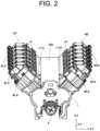
- Fig. 2 is a schematic perspective view extracting and showing a portion including the cylinder block 1, the head block 4, and the head cover 5 which are provided in the engine 100.
- Fig. 3 shows a schematic cross-sectional view of the cylinder block 1 portion of the engine 100.
- a crankshaft 6 and a piston 7 which extend in the front and back direction are placed inside the cylinder block 1. That is, the engine 100 has the crankshaft 6 that is placed in the cylinder block 1.
- the interior of the cylinder block 1 connects to the interior of the oil pan 3 which is placed at the lower side and stores a lubricant oil.
- a flywheel 2 (see Fig. 1 ) is mounted to the back end of the crankshaft 6. That is, the engine 100 is provided with the flywheel 2 mounted to one end portion of the crankshaft 6.
- the flywheel 2 is mounted on the one end portion of the crankshaft 6 protruding from the cylinder block 1.
- the flywheel 2 rotates integrally with the crankshaft 6, and is used to take out power from the engine 100.
- the piston 7, in detail, is placed in the cylinder 11 formed in the cylinder block 1.
- the piston 7 is connected to the crankshaft 6 via a connecting rod 71.
- the cylinder block 1 has the cylinder 11 included in the combustion chamber.
- the cylinder block 1 has a right cylinder 11R placed on the right side and a left cylinder 11L placed on the left side.
- the right cylinder 11R when viewed from behind, is of a cylindrical shape which is tilted to the right relative to the up and down direction and extends in an oblique direction.
- the left cylinder 11L when viewed from behind, is of a cylindrical shape which is tilted to the left relative to the up and down direction and extends in an oblique direction.
- the right cylinder 11R and the left cylinder 11L are placed in a V-shape.
- the pairwise right cylinder 11R and left cylinder 11L which are placed in the V-shape are placed with their cylinder axes slightly offset in the front and back direction.
- the left cylinder 11L is placed slightly forward of the right cylinder 11R.
- the cylinder block 1 has a right cylinder row 111R with the plural right cylinders 11R arranged in the front and back direction, and a left cylinder row 111L with the plural left cylinders 11L arranged in the front and back direction. That is, the cylinder block 1 has the two cylinder rows 111R and 111L. In each of the two cylinder rows 111R and 111L, plural cylinders 11 are arranged in the crankshaft direction. The two cylinder rows 111R and 111L are arranged alongside each other. Further, the two cylinder rows 111R and 111L are arranged in the right and left direction in detail. The right cylinder row 111R and the left cylinder row 111L form a V-shaped bank.
- the two cylinder rows 111R and 111L form a V-bank.
- the number of right cylinders 11R included in the right cylinder row 111R and the number of left cylinders 11L included in the left cylinder row 111L are each six, as an example. That is, the engine 100 in the present embodiment is a V-type 12-cylinder engine. It is sufficient that the cylinder block 1 should have the cylinder 11 at least one in number on each of the one side and the other side in the direction intersecting the crankshaft direction. Then, it is sufficient that the V-bank should be formed by the 11 cylinders on the one side and the other side. The one side and the other side in the direction intersecting the crankshaft direction may be the right side and the left side.
- the head block 4 is placed overlapping each cylinder 11.
- the head block 4 is fastened to the cylinder block 1 by using a screw.
- the head block 4 includes a right head block 4R that overlaps the right cylinder 11R and a left head block 4L that overlaps the left cylinder 11L. Because one right head block 4R overlaps each right cylinder 11R, there are as many right head blocks 4R as there are right cylinders 11R. Because one left head block 4L is overlaps each left cylinder 11L, there are as many left head blocks 4L as there are left cylinders 11L.
- the number of right head blocks 4R and the number of left head blocks 4L are each six.
- Each of the head blocks 4 has an intake port 41 to supply gas to a combustion chamber including the cylinder 11, the piston 7, and the head block 4, and an exhaust port (not shown) to exhaust the gas from the combustion chamber.
- the exhaust port is provided on the opposite face of the face where the intake port 41 is provided.
- the right head block 4R has the intake port 41 on the left lateral face and the exhaust port on the right lateral face.
- the left head block 4L has the intake port 41 on the right lateral face and the exhaust port on the left lateral face.
- Each head block 4 is covered with the head cover 5.
- the head cover 5 is fastened to head block 4 by using a screw.
- Each head cover 5 covers intake and exhaust valves (not shown) placed at the head block 4.
- An injector 8 is mounted on each head cover 5. The injector 8's one end portion, where an injection port for injecting a fuel is placed, faces the combustion chamber. The injector 8's another end portion projects outward from the head cover 5.
- the head cover 5 includes a right head cover 5R that covers the right head block 4R and a left head cover 5L that covers the left head block 4L.
- the right head covers 5R due to covering the respective right head blocks 4R, are the same in number as the right head blocks 4R.
- the left head covers 5L due to covering the respective left head blocks 4L, are the same in number as the left head blocks 4L.
- the number of right head cover 5R and left head cover 5L are each six.
- the number of right injectors 8R placed at the right head cover 5R and the number of left injectors 8L placed at the left head cover 5L are each six.
- the right cylinder 11R, the right head block 4R and the right head cover 5R which are included in a right bank RB, extend diagonally upward to the right.
- the left cylinder 11L, the left head block 4L, and the left head cover 5L which are included in a left bank LB, extend diagonally upward to the left.
- a combination of the right bank RB and the left bank LB is V-shaped, and the engine 100 has a V-bank.
- An intra-bank area 200 is formed between the right bank RB and the left bank LB in the right and left direction.
- the engine 100 has an upper face cover 9 and a lateral face cover 10.
- the upper face cover 9 prevents water from splashing, due to condensation, for example, onto a controller 26 (see Fig. 4 , etc., below) and the like placed inside.
- the lateral face cover 10 prevents the fuel from splashing due to a crack, etc. in a component part such as the head block 4, for example.
- Fig. 1 shows only the lateral face cover 10 placed on the right lateral face, a similar lateral face cover 10 is also placed on the left lateral face. That is, the engine 100 is equipped with a pair of right and left lateral face covers 10.
- Fig. 4 is a schematic top view showing the configuration of the engine 100 according to the embodiment of the present invention.
- the upper face cover 9 and the pair of lateral face cover 10 are omitted.
- the engine 100 includes an intake manifold 21 and an exhaust manifold 22.
- the intake manifold 21 distributes intake air which is air or mixture air taken in from the outside.
- the intake manifold 21 is placed at an upper portion of the engine 100, and extends in the front and back direction.
- the intake manifold 21 includes a right intake manifold 21R for the right cylinder 11R, and a left intake manifold 21L for the left cylinder 11L. That is, the engine 100 has two intake manifolds 21R and 21L.
- the right intake manifold 21R is placed above the respective intake ports 41 (see Fig. 2 ) of the plural right head blocks 4R which are arranged in the front and back direction.
- the interior of the right intake manifold 21R and the respective right cylinders 11R are connected via the respective intake ports 41.
- the left intake manifold 21L is placed above the respective intake ports 41 of the plural left head blocks 4L which are arranged in the front and back direction.
- the interior of the left intake manifold 21L and the respective left cylinders 11L are connected via the respective intake ports 41.
- an intake valve (not shown) is interposed between each intake port 41 and each cylinder 11; when the intake valve is open, the inside of intake manifold 21 and cylinder 11 are communicated.
- the exhaust manifold 22 collects the exhaust air from the respective cylinders 11.
- the exhaust manifold 22 is placed at the lateral face portion of the engine 100, and extends in the front and back direction.
- the exhaust manifold 22 includes a right exhaust manifold 22R for the right cylinder 11R, and a left exhaust manifold 22L for the left cylinder 11L.
- the right exhaust manifold 22R is placed on the right side of the plural right head blocks 4R (see Fig. 2 ) which are arranged in the front and back direction.
- the inside of the right exhaust manifold 22R and the respective right cylinders 11R are connected via exhaust ports (not shown) provided on the right side of the right head blocks 4R.
- the left exhaust manifold 22L is placed on the left side of the plural left head blocks 4L (see Fig. 2 ) which are arranged in the front and back direction.
- the inside of the left exhaust manifold 22L and the respective left cylinders 11L are connected via the exhaust ports (not shown) provided on the left side of the left head blocks 4L.
- an exhaust valve (not shown) is interposed between each exhaust port and each cylinder 11; when the exhaust valve is open, the inside of the exhaust manifold 22 and the cylinder 11 are communicated.
- the exhaust gas collected at the right exhaust manifold 22R is exhausted to the outside via the right turbocharger 23R and the right exhaust outlet pipe 24R which are each placed at the right back of the engine 100.
- the exhaust gas collected at the left exhaust manifold 22L is exhausted to the outside via the left turbocharger 23L and the left exhaust outlet pipe 24L which are each placed at the left back of the engine 100.
- the right turbocharger 23R and the left turbocharger 23L each have a compressor unit 231 and a turbine unit 232.
- the compressor unit 231 pressurizes and compresses intake air such as air supplied from outside the engine 100.
- the pressurized and compressed intake air is supplied via an intercooler 25 to the intake manifold 21.
- the turbine unit 232 is rotated by the exhaust gas supplied from the exhaust manifold 22.
- the rotary power of the turbine unit 232 is transmitted to the compressor unit 231. That is, the right turbocharger 23R and left turbocharger 23L in the present embodiment are so-called turbochargers that are driven by an exhaust gas turbine.
- the intercooler 25 which is connected with the intake manifold 21, is supplied with cooling water by a cooling water pump (not shown), thereby to cool the intake air.
- the intake air supplied from the compressor unit 231 is pressurized and compressed, thereby to generate a compression heat and to be increased in temperature.
- the intercooler 25 performs heat exchange between the cooling water, which is supplied by the cooling water pump, and the pressurized compressed intake air, thereby to cool the intake air. That is, providing the intercooler 25 allows the temperature of the intake air, which is supplied to the intake manifold 21, to be adjusted to a desired temperature.
- the right intake manifold 21R and the left intake manifold 21L are spaced apart and arranged in the right and left direction at the upper portion of the engine 100.
- the intra-bank area 200 is exposed to the outside via a space between the right intake manifold 21R and the left intake manifold 21L.
- the controller 26, which controls the entire engine 100 and a fuel pump 27 that supplies the fuel to the injector 8.
- the engine 100 includes the controller 26 placed in the intra-bank area 200 positioned between the right and left cylinder rows 111R and 111L. Also, the engine 100 includes the fuel pump 27 placed in the intra-bank area 200.
- the intra-bank area 200 may be, in a strict sense, a space area between the right and left cylinder rows 111R and 111L. In the present embodiment, however, the intra-bank area 200 widely includes the space area in the right and left direction between the right bank RB which includes the right cylinder row 111R, and the left bank LB which includes the left cylinder row 111L.
- Creating the configuration to place the controller 26 and fuel pump 27 in the intra-bank area 200 can efficiently use the intra-bank area 200 for placing the component part. This makes it possible to downsize the engine 100. However, the controller 26 and the fuel pump 27 may be placed outside of the intra-bank area 200.
- the controller 26 includes, in detail, a first controller 261 and a second controller 262.
- the number of controllers 26 may be changed as needed; for example, the controller 26 may include only one controller.
- the first controller 261 and the second controller 262 are arranged in the front and back direction (crankshaft direction).
- the first controller 261 is placed forward of the second controller 262.
- One of the first controller 261 and the second controller 262 is a main controller and another thereof is a sub-controller.
- the first controller 261 is the main controller
- the second controller 262 is the sub-controller.
- the first controller 261 configured as the main controller executes a calculation necessary to control the engine 100.
- the calculations required to control the engine 100 include, for example, a calculation related to the control of fuel injection and a calculation related to stopping the engine 100.
- the second controller 262 which is configured as the sub-controller is connected with the first controller 261 by a communication line (not shown), and is so provided as to be capable of communicating with the first controller 261.
- the second controller 262 executes a control operation according to an instruction from the first controller 261.
- the first controller 261 controls the right injector 8R placed at the right bank RB. That is, the first controller 261 and each right injector 8R are electrically connected. Further, the second controller 262 controls the left injector 8L placed at the left bank LB. That is, the second controller 262 and each left injector 8L are electrically connected.
- the fuel pump 27 discharges the fuel, which is at a high pressure, toward a high pressure fuel pipe (not shown) for the right bank RB and a high pressure fuel pipe (not shown) for the left bank LB.
- the fuel passing through the high-pressure fuel pipe for the right bank RB is distributed to each of the right injectors 8R placed at the right bank RB.
- the fuel passing through the high-pressure fuel pipe for the left bank LB is distributed to each of the left injectors 8L placed at the left bank LB.
- each of the injectors 8 injects the fuel to the combustion chamber.
- the engine 100 is provided with a path (hereinafter simply described as discharge path) that discharges, from within the cylinder block 1, the blow-by gas leaked out of the combustion chamber.
- the blow-by gases include an unburned gas, a combustion gas, and an oil vapor.
- Fig. 5 is a schematic perspective view extracting and showing an element that constitutes the blow-by gas's discharge path provided in the engine 100 according to the embodiment of the present invention.
- the elements that constitute the blow-by gas discharge path include the cylinder block 1, a flywheel housing 28, a gas pipe 29, and an oil separator 30.
- the engine 100 has the cylinder block 1, the flywheel housing 28, the gas pipe 29, and the oil separator 30.
- Fig. 6 is a schematic perspective view showing a configuration of the cylinder block 1 provided in the engine 100 according to the embodiment of the present invention.
- the cylinder block 1 has two cylinder rows 111R and 111L forming the V-bank as described above, and extends in the crankshaft direction (front and back direction).
- the cylinder block 1 has an inner space 1a (hereinafter expressed as intra-block space 1a).
- a camshaft 33 (see Fig. 9 below) and the like, for example, are placed in the intra-block space 1a.
- the front and rear faces of the cylinder block 1 are provided with camshaft holes 1b through which the camshaft passes.
- the cylinder block 1 is provided with a plurality of shaft insertion holes 1c through which control shafts (each not shown) which, in combination with the camshaft 33, control the opening and closing operations of the intake or exhaust valve.
- the blow-by gas leaking out of the combustion chamber which is configured for each of the cylinders 11, enters the intra-block space 1a.
- the cylinder block 1 on one end face thereof in the crankshaft direction, has a discharge port 1d that discharges the blow-by gas.
- the discharge port 1d is provided on the rear face of the cylinder block 1.
- the discharge port 1d is provided so as to discharge, out of the intra-block space 1a, the blow-by gas leaked out of the combustion chamber to the intra-block space 1a.
- the discharge port 1d is provided at the upper portion on the rear face of the cylinder block 1.
- the discharge port 1d is provided above the crankshaft 6 (see Fig. 9 below).
- the discharge port 1d is provided further above the camshaft hole 1b placed above the crankshaft 6.
- the cylinder block 1 has two openings 1e on the upper faces positioned between the two cylinder rows 111R and 111L in the right and left direction. These openings 1e are covered with a block upper face cover 34 (see Fig. 9 below). That is, the blow-by gas is not discharged out of the intra-block space 1a from these two openings 1e. It is allowed that the two openings 1e should not be provided.
- the flywheel housing 28 is placed on a side of one end face of the cylinder block 1 in the crankshaft direction.
- the flywheel housing 28 houses the flywheel 2 (see Fig. 1 ).
- the flywheel housing 28 is placed on the rear face side of the cylinder block 1.
- the flywheel housing 28 is mounted on the cylinder block 1.
- the flywheel housing 28 is mounted directly on the cylinder block 1. That is, the rear face of the cylinder block 1 includes a housing mounting face 1f that is mounted to the flywheel housing 28.
- the front face of the flywheel housing 28 includes a block mounting face 28a (see Fig. 8 below) mounted to the cylinder block 1. In a state of the flywheel housing 28 being mounted to the cylinder block 1, the housing mounting face 1f and the block mounting face 28a contact each other.
- the rear face of the cylinder block 1 is provided with a concave portion 1g concaved in a manner to face forward.
- the rear face of the cylinder block 1 includes the above housing mounting face 1f which constitutes an outer edge of the concave portion 1g, and a bottom face 1h of the concave portion 1g.
- the bottom face 1h of the concave portion 1g is placed forward of the housing mounting face 1f.
- the discharge port 1d is provided at the bottom face 1h of the concave portion 1g.
- Fig. 7 is a schematic perspective view showing a configuration of the flywheel housing 28 provided in the engine 100 according to the embodiment of the present invention.
- Fig. 8 is a schematic perspective view of the flywheel housing 28, viewed from a direction different from in Fig. 7.
- Fig. 7 is a diagram of the flywheel housing 28, viewed from the rear, diagonally upward to the right.
- Fig. 8 is a diagram of the flywheel housing 28, viewed from the front, diagonally upward to the right.
- the flywheel housing 28 has a housing body portion 281 that houses the flywheel 2, a housing upper piece portion 282, and a housing lower piece portion 283.
- the housing body portion 281 is circular in plan view from the front and back direction. As shown in Fig. 7 , the rear face of the housing body portion 281 is provided with a rear face concave portion 284 that is concaved toward the front.
- the rear face of the housing body portion 281 includes a ring-shaped face 2841 that constitutes an outer edge of the rear face concave portion 284 and a bottom face 2842 of the rear face concave portion 284.
- the bottom face 2842 of the rear face concave portion 284 is placed forward of the ring-shaped face 2841.
- the bottom face 2842 of the rear face concave portion 284 is provided with a crankshaft hole 285 that penetrates through the housing body portion 281 in the front and back direction.
- the rear end portion of the crankshaft 6 is inserted into the crankshaft hole 285, and is secured to the flywheel 2 housed in the rear face concave portion 284 (see Fig. 9 , etc. below).
- the housing upper piece portion 282 extends upward from the housing body portion 281.
- the housing lower piece portion 283 extends downward from the housing body portion 281.
- the front face of the flywheel housing 28 is provided with a front face concave portion 286 that is concaved toward the rear.
- the front face concave portion 286 extends in the up and down direction.
- the front face concave portion 286 extends in a strip form from the housing upper piece portion 282 to the housing lower piece portion 283.
- the front face of the flywheel housing 28 includes an outer edge face 2861 constituting an outer edge of the front face concave portion 286 and a bottom face 2862 of the front face concave portion 286.
- the bottom face 2862 of the front face concave portion 286 is placed behind the outer edge face 2861.
- the bottom face 2862 of the front face concave portion 286 is provided with the above crankshaft hole 285.
- the outer edge face 2861 includes the above block mounting face 28a.
- the outer edge face 2861 includes an oil pan mounting face 28b mounted to the rear face of the oil pan 3 placed below the cylinder block 1.
- the outer edge face 2861 includes a support base mounting face 28c that is mounted to the rear face of a fuel pump support base 31 (see Fig. 5 , etc.) placed above the cylinder block 1.
- the fuel pump support base 31 is a support stand for supporting the above fuel pump 27 placed in the intra-bank area 200.
- the housing upper piece portion 282 is provided with a first upper piece portion opening 2821 and a second upper piece portion opening 2822 that penetrate through the housing upper piece portion 282 in the front and back direction.
- the first upper piece portion opening 2821 and the second upper piece portion opening 2822 are arranged in the right and left direction.
- the first upper piece portion opening 2821 is positioned to the left of the second upper piece portion opening 2822.
- the first upper piece portion opening 2821 and the second upper piece portion opening 2822 connect with the front face concave portion 286.
- the housing upper piece portion 282 may be configured with only one opening.
- the second upper piece portion opening 2822 is so provided that the number of revolutions can be measured by a tachometer.
- the second upper piece portion opening 2822 as shown in Fig. 5 , is blocked by an opening portion cover 32 at the time of a normal use. If measurement of the number of revolutions is not needed, the second upper piece portion opening 2822 may be omitted.
- Fig. 9 is a diagram for explaining about flow of the blow-by gas, in the engine 100 according to the embodiment of the present invention.
- Fig. 9 is a schematic cross-sectional perspective view extracting and showing part of components of the engine 100.
- the white arrow shows the flow of the blow-by gas.
- the blow-by gas leaked out of the combustion chamber and having entered the intra-block space 1a is discharged via the discharge port 1d out of the intra-block space 1a.
- the discharge port 1d connects with the front face concave portion 286 of the flywheel housing 28. That is, the blow-by gas discharged from the discharge port 1d enters the front face concave portion 286. As shown in Fig. 9 , the blow-by gas entering the front face concave portion 286 is discharged via the first upper piece portion opening 2821 above the discharge port 1d toward the rear of the flywheel housing 28.
- blow-by gas having entered the front face concave portion 286 from the discharge port 1d passes through the space enclosed by the rear face of the fuel pump support base 31 placed in front of the flywheel housing 28, and by the face constituting the front face concave portion 286, in detail, and reaches the first upper piece portion opening 2821.
- the flywheel housing 28 has a blow-by gas path GP through which the blow-by gas leaking out of the combustion chamber passes.
- the blow-by gas path GP includes the front face concave portion 286 and the first upper piece portion opening 2821.
- the discharge port 1d communicates with the blow-by gas path GP.
- blow-by gas path GP is provided in the flywheel housing 28 makes it possible to provide the discharge port 1d, which discharges the blow-by gas, on one end face of the cylinder block 1 in the crankshaft direction. This eliminates the need for an action that is required for placing the blow-by gas's discharge port on the upper face of the cylinder block 1. For example, it is unnecessary to increase the cylinder block 1's length in the crankshaft direction so as to secure a place to place the discharge port. As a result, enlarging of the engine 100 can be avoided.
- the gas pipe that leads, to any other place, the blow-by gas discharged out of the cylinder block 1 can be placed on a side of one end face of the engine 100 in the crankshaft direction.
- the gas pipe for flowing the blow-by gas can be easily placed without an interference with any component included in the engine 100.
- the blow-by gas discharged backward from the first upper piece portion opening 2821 flows through in the gas pipe 29 and is sent to the oil separator 30.
- the gas pipe 29 enables the blow-by gas, which passes through the blow-by gas path GP, to be distributed to the V-bank side.
- the gas pipe 29 extends from the position where the first upper piece portion opening 2821 is provided to between the two intake manifolds 21R and 21L in the right and left direction which are placed in the intra-bank area 200 (see also Figs. 1 and 4 ).
- the oil separator 30 is connected with the gas pipe 29, and separates an oil component included in the blow-by gas.
- the oil separator 30 collects and separates an oil mist as a vaporized lubricant component included in the blow-by gas. That is, the oil separator 30 functions as an oil mist separator.
- the oil separator 30 discharges the gas remaining after the oil component's being removed from the blow-by gas.
- the oil separator 30, by means of an oil piping (not shown), returns the oil component separated from the blow-by gas.
- the oil separator 30 is positioned between the two intake manifolds 21R and 21L in the right and left direction which are placed in the intra-bank area 200 (see Fig. 4 ). That is, the oil separator 30 is placed by an effective use of the space created inside the engine 100.
- the oil separator 30 includes a right oil separator 30R and a left oil separator 30L which are arranged in the right and left direction.
- the right oil separator 30R is placed to the right of the left oil separator 30L.
- the number of oil separators 30 provided in the engine 100 may be modified as needed, and may be single or three or more.
- the gas pipe 29 includes a common gas pipe 291, a right gas pipe 292, and a left gas pipe 293.
- the configuration of the gas pipe 29 may be changed as needed depending on the number of oil separators 30.
- the common gas pipe 291 has a branch portion 2911, a right pipe portion 2912, and a left pipe portion 2913.
- the branch portion 2911 is positioned in the center of the common gas pipe 291, and is mounted to the rear face of the housing upper piece portion 282.
- the branch portion 2911 covers the first upper piece portion opening 2821.
- the front face of the branch portion 2911 has a concave portion (not shown) that is concaved toward the rear.
- the above concave portion communicates with the first upper piece portion opening 2821.
- the right pipe portion 2912 is a pipe-shaped extending rightward from the branch portion 2911, and has an interior communicating with the concave portion of the branch portion 2911.
- the left pipe portion 2913 is a pipe-shaped extending leftward from the branch portion 2911, and has an interior communicating with the concave portion of the branch portion 2911.
- the right gas pipe 292 is connected at one end thereof with the right pipe portion 2912 of the common gas pipe 291 and at the other end thereof with the right oil separator 30R.
- the left gas pipe 293 is connected at one end thereof with the left pipe portion 2913 of the common gas pipe 291 and at the other end thereof with the left oil separator 30L. From the common gas pipe 291 placed below the intercooler 25, the right gas pipe 292 extends in a curved to the space that is in front of the intercooler 25 and that is between the two intake manifolds 21R and 21L, and is connected to the right oil separator 30R.
- the left gas pipe 293 extends in a curved manner to the space that is in front of the intercooler 25 and that is between the two intake manifolds 21R and 21L, and is connected to the left oil separator 30L.
- the blow-by gas discharged backward from the first upper piece portion opening 2821 is branched to the right and left at the branch portion 2911 of the common gas pipe 291.
- the blow-by gas branched to the right pipe portion 2912 at the branch portion 2911 passes through the right pipe portion 2912 and the right gas pipe 292 thereby to reach the right oil separator 30R, where the oil component is removed and discharged to the outside.
- the blow-by gas branched to the left pipe portion 2913 at the branch portion 2911 passes through the left pipe portion 2913 and the left gas pipe 293 thereby to reach the left oil separator 30L, where the oil component is removed and discharged to the outside.
- the engine 100 is the V-type engine, but this is merely an exemplification.
- the present invention can be applied, for example, to an in-line engine in which the pistons reciprocate in the up and down direction and a horizontally opposed engine in which the pistons reciprocate in the horizontal direction.
Landscapes
- Engineering & Computer Science (AREA)
- Mechanical Engineering (AREA)
- General Engineering & Computer Science (AREA)
- Chemical & Material Sciences (AREA)
- Combustion & Propulsion (AREA)
- Ocean & Marine Engineering (AREA)
- Lubrication Details And Ventilation Of Internal Combustion Engines (AREA)
- Cylinder Crankcases Of Internal Combustion Engines (AREA)
Abstract
[Problem] To provide, while avoiding enlarging of an engine, a technology that can properly discharge a blow-by gas out of a cylinder block.
[Solution] An exemplary engine includes: a cylinder block that has a cylinder included in a combustion chamber; a crankshaft that is placed in the cylinder block; a flywheel that is mounted to one end portion of the crankshaft; and a flywheel housing that is placed on a side of one end face of the cylinder block in a direction of the crankshaft and that houses the flywheel. The flywheel housing has a blow-by gas path through which a blow-by gas passes.
Description
- The present invention relates to an engine and a flywheel housing.
- Conventionally, there is a known technology that, out of a crankcase (cylinder block), efficiently discharges a blow-by gas which flows from a combustion chamber into an inner space of the crankcase (see, for example, Patent Document 1). The crankcase of the
Patent Document 1 includes a blow-by gas path that is formed inside the crankcase, and that discharges the blow-by gas inside the crankcase to the upper portion of the crankcase. - Patent Document 1:
Japanese Unexamined Patent Application Publication No. 2005-140104 - In the configuration of the
Patent Document 1, an outlet of the blow-by gas path is provided on the upper face of the crankcase. Usually, there is very little free space on the crankcase's upper face, where a cylinder head, an intake manifold, etc. are placed. Due to this, it is not easy to place a gas pipe for leading, to another place, the blow-by gas output from the blow-by gas path. Trying to place the gas pipe connected to the blow-by gas's outlet provided on the upper face of the crankcase needs to take an action such as increasing the overall length of the crankcase so as to avoid contact with the cylinder head and the like. There is a concern that increasing the overall length of the crankcase enlarges the engine. - It is an object of the present invention to provide, while avoiding enlarging of an engine, a technology that can properly discharge a blow-by gas out of a cylinder block.
- An engine exemplary of the present invention includes: a cylinder block that has a cylinder included in a combustion chamber; a crankshaft that is placed in the cylinder block; a flywheel that is mounted to one end portion of the crankshaft; and a flywheel housing that is placed on a side of one end face of the cylinder block in a direction of the crankshaft and that houses the flywheel. The flywheel housing has a blow-by gas path through which a blow-by gas passes.
- The exemplary present invention can provide, while avoiding enlarging of an engine, a technology that can properly discharge a blow-by gas out of a cylinder block.
-
-
Fig. 1 is a schematic perspective view showing a configuration of an engine. -
Fig. 2 is a schematic perspective view extracting and showing a portion including a cylinder block, a head block, and a head cover which are provided in the engine. -
Fig. 3 is a schematic cross-sectional view of a cylinder block portion provided in the engine. -
Fig. 4 is a schematic top view showing the configuration of the engine. -
Fig. 5 is a schematic perspective view extracting and showing an element that constitutes a discharge path of a blow-by gas. -
Fig. 6 is a schematic perspective view showing a configuration of the cylinder block. -
Fig. 7 is a schematic perspective view showing a configuration of a flywheel housing. -
Fig. 8 is a schematic perspective view of the flywheel housing, viewed from a direction different from inFig. 7 . -
Fig. 9 is a diagram for explaining about flow of the blow-by gas. - The following is a detailed description of an exemplary embodiment of the present invention with reference to the drawings. In the drawings, XYZ coordinate system is shown as the 3D Cartesian coordinate system, as appropriate. In the following description, X direction is defined as a front and back direction, Y direction is defined as a right and left direction, and Z direction is defined as an up and down direction. +X side is defined as a front side, and -X side is defined as a back side. +Y side is defined as a right side, and -Y side is defined as the left side. +Z side is defined as an upper side, and -Z side is defined as a lower side. In detail, the direction in which a center line C of a crankshaft (output shaft) shown in
Fig. 1 extends is defined as the front and back direction, and the side where aflywheel 2 is placed relative to acylinder block 1 is defined as the back side. The up and down direction is defined with the side, where anoil pan 3 is placed relative to thecylinder block 1, as the lower side. The direction orthogonal to the front and back and up and down directions is defined as the right and left direction, with the right side being the right side and the left side being the left side when viewed from the back toward the front. These directions are names merely used for an illustrative purpose, and are not intended to limit the actual positional relation and direction. In the present specification, the crankshaft direction is the same as the front and back direction in which the center line C of the crankshaft extends. -
Fig. 1 is a schematic perspective view showing a configuration of anengine 100 according to an embodiment of the present invention. Theengine 100 is preferable, for example, as a marine engine used for a ship. However, theengine 100 is not limited to the marine engine, and may be applied to any other application. Theengine 100 is a diesel engine. - As shown in
Fig. 1 , theengine 100 includes acylinder block 1, ahead block 4, and ahead cover 5.Fig. 2 is a schematic perspective view extracting and showing a portion including thecylinder block 1, thehead block 4, and thehead cover 5 which are provided in theengine 100.Fig. 3 shows a schematic cross-sectional view of thecylinder block 1 portion of theengine 100. - As shown in
Figs. 2 and3 , acrankshaft 6 and apiston 7 which extend in the front and back direction are placed inside thecylinder block 1. That is, theengine 100 has thecrankshaft 6 that is placed in thecylinder block 1. The interior of thecylinder block 1 connects to the interior of theoil pan 3 which is placed at the lower side and stores a lubricant oil. A flywheel 2 (seeFig. 1 ) is mounted to the back end of thecrankshaft 6. That is, theengine 100 is provided with theflywheel 2 mounted to one end portion of thecrankshaft 6. In detail, theflywheel 2 is mounted on the one end portion of thecrankshaft 6 protruding from thecylinder block 1. Theflywheel 2 rotates integrally with thecrankshaft 6, and is used to take out power from theengine 100. Thepiston 7, in detail, is placed in thecylinder 11 formed in thecylinder block 1. Thepiston 7 is connected to thecrankshaft 6 via a connectingrod 71. - The
cylinder block 1 has thecylinder 11 included in the combustion chamber. In detail, thecylinder block 1 has aright cylinder 11R placed on the right side and a left cylinder 11L placed on the left side. Theright cylinder 11R, when viewed from behind, is of a cylindrical shape which is tilted to the right relative to the up and down direction and extends in an oblique direction. The left cylinder 11L, when viewed from behind, is of a cylindrical shape which is tilted to the left relative to the up and down direction and extends in an oblique direction. Theright cylinder 11R and the left cylinder 11L are placed in a V-shape. The pairwiseright cylinder 11R and left cylinder 11L which are placed in the V-shape are placed with their cylinder axes slightly offset in the front and back direction. In the present embodiment, the left cylinder 11L is placed slightly forward of theright cylinder 11R. - The
cylinder block 1 has aright cylinder row 111R with the pluralright cylinders 11R arranged in the front and back direction, and aleft cylinder row 111L with the plural left cylinders 11L arranged in the front and back direction. That is, thecylinder block 1 has the twocylinder rows cylinder rows plural cylinders 11 are arranged in the crankshaft direction. The twocylinder rows cylinder rows right cylinder row 111R and theleft cylinder row 111L form a V-shaped bank. That is, in theengine 100, the twocylinder rows right cylinders 11R included in theright cylinder row 111R and the number of left cylinders 11L included in theleft cylinder row 111L are each six, as an example. That is, theengine 100 in the present embodiment is a V-type 12-cylinder engine. It is sufficient that thecylinder block 1 should have thecylinder 11 at least one in number on each of the one side and the other side in the direction intersecting the crankshaft direction. Then, it is sufficient that the V-bank should be formed by the 11 cylinders on the one side and the other side. The one side and the other side in the direction intersecting the crankshaft direction may be the right side and the left side. - In each of the right and left
cylinder rows head block 4 is placed overlapping eachcylinder 11. Thehead block 4 is fastened to thecylinder block 1 by using a screw. In detail, thehead block 4 includes aright head block 4R that overlaps theright cylinder 11R and aleft head block 4L that overlaps the left cylinder 11L. Because oneright head block 4R overlaps eachright cylinder 11R, there are as many right head blocks 4R as there areright cylinders 11R. Because oneleft head block 4L is overlaps each left cylinder 11L, there are as many left head blocks 4L as there are left cylinders 11L. In the present embodiment, the number of right head blocks 4R and the number ofleft head blocks 4L are each six. - Each of the head blocks 4 has an
intake port 41 to supply gas to a combustion chamber including thecylinder 11, thepiston 7, and thehead block 4, and an exhaust port (not shown) to exhaust the gas from the combustion chamber. The exhaust port is provided on the opposite face of the face where theintake port 41 is provided. In detail, theright head block 4R has theintake port 41 on the left lateral face and the exhaust port on the right lateral face. Theleft head block 4L has theintake port 41 on the right lateral face and the exhaust port on the left lateral face. - Each
head block 4 is covered with thehead cover 5. Thehead cover 5 is fastened to headblock 4 by using a screw. Eachhead cover 5 covers intake and exhaust valves (not shown) placed at thehead block 4. Aninjector 8 is mounted on eachhead cover 5. Theinjector 8's one end portion, where an injection port for injecting a fuel is placed, faces the combustion chamber. Theinjector 8's another end portion projects outward from thehead cover 5. - In detail, the
head cover 5 includes aright head cover 5R that covers theright head block 4R and aleft head cover 5L that covers theleft head block 4L. The right head covers 5R, due to covering the respective right head blocks 4R, are the same in number as the right head blocks 4R. The left head covers 5L, due to covering the respective left head blocks 4L, are the same in number as the left head blocks 4L. In the present embodiment, the number ofright head cover 5R and lefthead cover 5L are each six. Also, the number ofright injectors 8R placed at theright head cover 5R and the number ofleft injectors 8L placed at theleft head cover 5L are each six. - On the right side of
cylinder block 1, theright cylinder 11R, theright head block 4R and theright head cover 5R, which are included in a right bank RB, extend diagonally upward to the right. On the left side ofcylinder block 1, the left cylinder 11L, theleft head block 4L, and theleft head cover 5L, which are included in a left bank LB, extend diagonally upward to the left. In plan view from the front and back direction, a combination of the right bank RB and the left bank LB is V-shaped, and theengine 100 has a V-bank. Anintra-bank area 200 is formed between the right bank RB and the left bank LB in the right and left direction. - Returning to
Fig. 1 , theengine 100 has anupper face cover 9 and alateral face cover 10. Theupper face cover 9 prevents water from splashing, due to condensation, for example, onto a controller 26 (seeFig. 4 , etc., below) and the like placed inside. Thelateral face cover 10 prevents the fuel from splashing due to a crack, etc. in a component part such as thehead block 4, for example. AlthoughFig. 1 shows only thelateral face cover 10 placed on the right lateral face, a similarlateral face cover 10 is also placed on the left lateral face. That is, theengine 100 is equipped with a pair of right and left lateral face covers 10. -
Fig. 4 is a schematic top view showing the configuration of theengine 100 according to the embodiment of the present invention. InFig. 4 , theupper face cover 9 and the pair oflateral face cover 10 are omitted. As shown inFigs. 1 and4 , theengine 100 includes anintake manifold 21 and anexhaust manifold 22. - To each of the
cylinders 11, theintake manifold 21 distributes intake air which is air or mixture air taken in from the outside. Theintake manifold 21 is placed at an upper portion of theengine 100, and extends in the front and back direction. In detail, theintake manifold 21 includes aright intake manifold 21R for theright cylinder 11R, and aleft intake manifold 21L for the left cylinder 11L. That is, theengine 100 has twointake manifolds - The
right intake manifold 21R is placed above the respective intake ports 41 (seeFig. 2 ) of the plural right head blocks 4R which are arranged in the front and back direction. The interior of theright intake manifold 21R and the respectiveright cylinders 11R are connected via therespective intake ports 41. Theleft intake manifold 21L is placed above therespective intake ports 41 of the plural left head blocks 4L which are arranged in the front and back direction. The interior of theleft intake manifold 21L and the respective left cylinders 11L are connected via therespective intake ports 41. - In detail, an intake valve (not shown) is interposed between each
intake port 41 and eachcylinder 11; when the intake valve is open, the inside ofintake manifold 21 andcylinder 11 are communicated. - The
exhaust manifold 22 collects the exhaust air from therespective cylinders 11. Theexhaust manifold 22 is placed at the lateral face portion of theengine 100, and extends in the front and back direction. In detail, theexhaust manifold 22 includes aright exhaust manifold 22R for theright cylinder 11R, and a left exhaust manifold 22L for the left cylinder 11L. - The
right exhaust manifold 22R is placed on the right side of the plural right head blocks 4R (seeFig. 2 ) which are arranged in the front and back direction. The inside of theright exhaust manifold 22R and the respectiveright cylinders 11R are connected via exhaust ports (not shown) provided on the right side of the right head blocks 4R. The left exhaust manifold 22L is placed on the left side of the plural left head blocks 4L (seeFig. 2 ) which are arranged in the front and back direction. The inside of the left exhaust manifold 22L and the respective left cylinders 11L are connected via the exhaust ports (not shown) provided on the left side of the left head blocks 4L. - In detail, an exhaust valve (not shown) is interposed between each exhaust port and each
cylinder 11; when the exhaust valve is open, the inside of theexhaust manifold 22 and thecylinder 11 are communicated. - The exhaust gas collected at the
right exhaust manifold 22R is exhausted to the outside via theright turbocharger 23R and the rightexhaust outlet pipe 24R which are each placed at the right back of theengine 100. The exhaust gas collected at the left exhaust manifold 22L is exhausted to the outside via theleft turbocharger 23L and the leftexhaust outlet pipe 24L which are each placed at the left back of theengine 100. - The
right turbocharger 23R and theleft turbocharger 23L each have acompressor unit 231 and aturbine unit 232. Thecompressor unit 231 pressurizes and compresses intake air such as air supplied from outside theengine 100. The pressurized and compressed intake air is supplied via anintercooler 25 to theintake manifold 21. Theturbine unit 232 is rotated by the exhaust gas supplied from theexhaust manifold 22. The rotary power of theturbine unit 232 is transmitted to thecompressor unit 231. That is, theright turbocharger 23R and leftturbocharger 23L in the present embodiment are so-called turbochargers that are driven by an exhaust gas turbine. - The
intercooler 25, which is connected with theintake manifold 21, is supplied with cooling water by a cooling water pump (not shown), thereby to cool the intake air. The intake air supplied from thecompressor unit 231 is pressurized and compressed, thereby to generate a compression heat and to be increased in temperature. Theintercooler 25 performs heat exchange between the cooling water, which is supplied by the cooling water pump, and the pressurized compressed intake air, thereby to cool the intake air. That is, providing theintercooler 25 allows the temperature of the intake air, which is supplied to theintake manifold 21, to be adjusted to a desired temperature. - As shown in
Fig. 4 , theright intake manifold 21R and theleft intake manifold 21L are spaced apart and arranged in the right and left direction at the upper portion of theengine 100. As shown inFig. 4 , with theupper face cover 9 removed, theintra-bank area 200 is exposed to the outside via a space between theright intake manifold 21R and theleft intake manifold 21L. In theintra-bank area 200, there are placed, for example, the controller 26, which controls theentire engine 100, and afuel pump 27 that supplies the fuel to theinjector 8. - That is, the
engine 100 includes the controller 26 placed in theintra-bank area 200 positioned between the right and leftcylinder rows engine 100 includes thefuel pump 27 placed in theintra-bank area 200. Theintra-bank area 200 may be, in a strict sense, a space area between the right and leftcylinder rows intra-bank area 200 widely includes the space area in the right and left direction between the right bank RB which includes theright cylinder row 111R, and the left bank LB which includes theleft cylinder row 111L. - Creating the configuration to place the controller 26 and
fuel pump 27 in theintra-bank area 200 can efficiently use theintra-bank area 200 for placing the component part. This makes it possible to downsize theengine 100. However, the controller 26 and thefuel pump 27 may be placed outside of theintra-bank area 200. - Further, the controller 26 includes, in detail, a first controller 261 and a second controller 262. However, the number of controllers 26 may be changed as needed; for example, the controller 26 may include only one controller. In the present embodiment, the first controller 261 and the second controller 262 are arranged in the front and back direction (crankshaft direction). In detail, the first controller 261 is placed forward of the second controller 262. One of the first controller 261 and the second controller 262 is a main controller and another thereof is a sub-controller. In the present embodiment, the first controller 261 is the main controller, and the second controller 262 is the sub-controller.
- The first controller 261 configured as the main controller executes a calculation necessary to control the
engine 100. The calculations required to control theengine 100 include, for example, a calculation related to the control of fuel injection and a calculation related to stopping theengine 100. The second controller 262 which is configured as the sub-controller is connected with the first controller 261 by a communication line (not shown), and is so provided as to be capable of communicating with the first controller 261. The second controller 262 executes a control operation according to an instruction from the first controller 261. - The first controller 261 controls the
right injector 8R placed at the right bank RB. That is, the first controller 261 and eachright injector 8R are electrically connected. Further, the second controller 262 controls theleft injector 8L placed at the left bank LB. That is, the second controller 262 and eachleft injector 8L are electrically connected. - Further, the
fuel pump 27 discharges the fuel, which is at a high pressure, toward a high pressure fuel pipe (not shown) for the right bank RB and a high pressure fuel pipe (not shown) for the left bank LB. The fuel passing through the high-pressure fuel pipe for the right bank RB is distributed to each of theright injectors 8R placed at the right bank RB. The fuel passing through the high-pressure fuel pipe for the left bank LB is distributed to each of theleft injectors 8L placed at the left bank LB. Under control by the controller 26, each of theinjectors 8 injects the fuel to the combustion chamber. - The
engine 100 is provided with a path (hereinafter simply described as discharge path) that discharges, from within thecylinder block 1, the blow-by gas leaked out of the combustion chamber. Further, the blow-by gases include an unburned gas, a combustion gas, and an oil vapor. -
Fig. 5 is a schematic perspective view extracting and showing an element that constitutes the blow-by gas's discharge path provided in theengine 100 according to the embodiment of the present invention. As shown inFig. 5 , the elements that constitute the blow-by gas discharge path include thecylinder block 1, aflywheel housing 28, agas pipe 29, and anoil separator 30. In other words, theengine 100 has thecylinder block 1, theflywheel housing 28, thegas pipe 29, and theoil separator 30. -
Fig. 6 is a schematic perspective view showing a configuration of thecylinder block 1 provided in theengine 100 according to the embodiment of the present invention. Thecylinder block 1 has twocylinder rows cylinder block 1 has aninner space 1a (hereinafter expressed asintra-block space 1a). Other than theabove crankshaft 6, a camshaft 33 (seeFig. 9 below) and the like, for example, are placed in theintra-block space 1a. The front and rear faces of thecylinder block 1 are provided withcamshaft holes 1b through which the camshaft passes. Further, thecylinder block 1 is provided with a plurality of shaft insertion holes 1c through which control shafts (each not shown) which, in combination with thecamshaft 33, control the opening and closing operations of the intake or exhaust valve. - The blow-by gas leaking out of the combustion chamber, which is configured for each of the
cylinders 11, enters theintra-block space 1a. Thecylinder block 1, on one end face thereof in the crankshaft direction, has adischarge port 1d that discharges the blow-by gas. In detail, thedischarge port 1d is provided on the rear face of thecylinder block 1. Thedischarge port 1d is provided so as to discharge, out of theintra-block space 1a, the blow-by gas leaked out of the combustion chamber to theintra-block space 1a. In the present embodiment, thedischarge port 1d is provided at the upper portion on the rear face of thecylinder block 1. Thedischarge port 1d is provided above the crankshaft 6 (seeFig. 9 below). Thedischarge port 1d is provided further above thecamshaft hole 1b placed above thecrankshaft 6. - In the present embodiment, as shown in
Fig. 6 , thecylinder block 1 has twoopenings 1e on the upper faces positioned between the twocylinder rows openings 1e are covered with a block upper face cover 34 (seeFig. 9 below). That is, the blow-by gas is not discharged out of theintra-block space 1a from these twoopenings 1e. It is allowed that the twoopenings 1e should not be provided. - The
flywheel housing 28 is placed on a side of one end face of thecylinder block 1 in the crankshaft direction. Theflywheel housing 28 houses the flywheel 2 (seeFig. 1 ). In detail, theflywheel housing 28 is placed on the rear face side of thecylinder block 1. Theflywheel housing 28 is mounted on thecylinder block 1. In the present embodiment, theflywheel housing 28 is mounted directly on thecylinder block 1. That is, the rear face of thecylinder block 1 includes ahousing mounting face 1f that is mounted to theflywheel housing 28. The front face of theflywheel housing 28 includes ablock mounting face 28a (seeFig. 8 below) mounted to thecylinder block 1. In a state of theflywheel housing 28 being mounted to thecylinder block 1, thehousing mounting face 1f and theblock mounting face 28a contact each other. - The rear face of the
cylinder block 1 is provided with aconcave portion 1g concaved in a manner to face forward. The rear face of thecylinder block 1 includes the abovehousing mounting face 1f which constitutes an outer edge of theconcave portion 1g, and abottom face 1h of theconcave portion 1g. Thebottom face 1h of theconcave portion 1g is placed forward of thehousing mounting face 1f. Thedischarge port 1d is provided at thebottom face 1h of theconcave portion 1g. -
Fig. 7 is a schematic perspective view showing a configuration of theflywheel housing 28 provided in theengine 100 according to the embodiment of the present invention.Fig. 8 is a schematic perspective view of theflywheel housing 28, viewed from a direction different from inFig. 7. Fig. 7 is a diagram of theflywheel housing 28, viewed from the rear, diagonally upward to the right.Fig. 8 is a diagram of theflywheel housing 28, viewed from the front, diagonally upward to the right. As shown inFigs. 7 and8 , theflywheel housing 28 has ahousing body portion 281 that houses theflywheel 2, a housingupper piece portion 282, and a housinglower piece portion 283. - The
housing body portion 281 is circular in plan view from the front and back direction. As shown inFig. 7 , the rear face of thehousing body portion 281 is provided with a rear faceconcave portion 284 that is concaved toward the front. The rear face of thehousing body portion 281 includes a ring-shapedface 2841 that constitutes an outer edge of the rear faceconcave portion 284 and abottom face 2842 of the rear faceconcave portion 284. Thebottom face 2842 of the rear faceconcave portion 284 is placed forward of the ring-shapedface 2841. Thebottom face 2842 of the rear faceconcave portion 284 is provided with acrankshaft hole 285 that penetrates through thehousing body portion 281 in the front and back direction. The rear end portion of thecrankshaft 6 is inserted into thecrankshaft hole 285, and is secured to theflywheel 2 housed in the rear face concave portion 284 (seeFig. 9 , etc. below). - The housing
upper piece portion 282 extends upward from thehousing body portion 281. The housinglower piece portion 283 extends downward from thehousing body portion 281. As shown inFig. 8 , the front face of theflywheel housing 28 is provided with a front faceconcave portion 286 that is concaved toward the rear. The front faceconcave portion 286 extends in the up and down direction. The front faceconcave portion 286 extends in a strip form from the housingupper piece portion 282 to the housinglower piece portion 283. - The front face of the
flywheel housing 28 includes anouter edge face 2861 constituting an outer edge of the front faceconcave portion 286 and abottom face 2862 of the front faceconcave portion 286. Thebottom face 2862 of the front faceconcave portion 286 is placed behind theouter edge face 2861. Thebottom face 2862 of the front faceconcave portion 286 is provided with theabove crankshaft hole 285. Theouter edge face 2861 includes the aboveblock mounting face 28a. Further, theouter edge face 2861 includes an oilpan mounting face 28b mounted to the rear face of theoil pan 3 placed below thecylinder block 1. Further, theouter edge face 2861 includes a supportbase mounting face 28c that is mounted to the rear face of a fuel pump support base 31 (seeFig. 5 , etc.) placed above thecylinder block 1. Further, the fuelpump support base 31 is a support stand for supporting theabove fuel pump 27 placed in theintra-bank area 200. - As shown in
Figs. 7 and8 , the housingupper piece portion 282 is provided with a first upperpiece portion opening 2821 and a second upperpiece portion opening 2822 that penetrate through the housingupper piece portion 282 in the front and back direction. The first upperpiece portion opening 2821 and the second upperpiece portion opening 2822 are arranged in the right and left direction. The first upperpiece portion opening 2821 is positioned to the left of the second upperpiece portion opening 2822. The first upperpiece portion opening 2821 and the second upperpiece portion opening 2822 connect with the front faceconcave portion 286. - Further, the housing
upper piece portion 282 may be configured with only one opening. In the present embodiment, the second upperpiece portion opening 2822 is so provided that the number of revolutions can be measured by a tachometer. The second upperpiece portion opening 2822, as shown inFig. 5 , is blocked by an openingportion cover 32 at the time of a normal use. If measurement of the number of revolutions is not needed, the second upperpiece portion opening 2822 may be omitted. -
Fig. 9 is a diagram for explaining about flow of the blow-by gas, in theengine 100 according to the embodiment of the present invention.Fig. 9 is a schematic cross-sectional perspective view extracting and showing part of components of theengine 100. InFig. 9 , the white arrow shows the flow of the blow-by gas. As shown inFig. 9 , the blow-by gas leaked out of the combustion chamber and having entered theintra-block space 1a is discharged via thedischarge port 1d out of theintra-block space 1a. - With the
flywheel housing 28 in a state of being mounted to thecylinder block 1, thedischarge port 1d connects with the front faceconcave portion 286 of theflywheel housing 28. That is, the blow-by gas discharged from thedischarge port 1d enters the front faceconcave portion 286. As shown inFig. 9 , the blow-by gas entering the front faceconcave portion 286 is discharged via the first upperpiece portion opening 2821 above thedischarge port 1d toward the rear of theflywheel housing 28. - Further, the blow-by gas having entered the front face
concave portion 286 from thedischarge port 1d passes through the space enclosed by the rear face of the fuelpump support base 31 placed in front of theflywheel housing 28, and by the face constituting the front faceconcave portion 286, in detail, and reaches the first upperpiece portion opening 2821. - That is, the
flywheel housing 28 has a blow-by gas path GP through which the blow-by gas leaking out of the combustion chamber passes. In the present embodiment, the blow-by gas path GP includes the front faceconcave portion 286 and the first upperpiece portion opening 2821. Thedischarge port 1d communicates with the blow-by gas path GP. - Creating the configuration in which the blow-by gas path GP is provided in the
flywheel housing 28 makes it possible to provide thedischarge port 1d, which discharges the blow-by gas, on one end face of thecylinder block 1 in the crankshaft direction. This eliminates the need for an action that is required for placing the blow-by gas's discharge port on the upper face of thecylinder block 1. For example, it is unnecessary to increase thecylinder block 1's length in the crankshaft direction so as to secure a place to place the discharge port. As a result, enlarging of theengine 100 can be avoided. According to this configuration, the gas pipe that leads, to any other place, the blow-by gas discharged out of thecylinder block 1 can be placed on a side of one end face of theengine 100 in the crankshaft direction. As a result, the gas pipe for flowing the blow-by gas can be easily placed without an interference with any component included in theengine 100. - As shown in
Fig. 5 , the blow-by gas discharged backward from the first upperpiece portion opening 2821 flows through in thegas pipe 29 and is sent to theoil separator 30. In the present embodiment, thegas pipe 29 enables the blow-by gas, which passes through the blow-by gas path GP, to be distributed to the V-bank side. In plan view from above, thegas pipe 29 extends from the position where the first upperpiece portion opening 2821 is provided to between the twointake manifolds Figs. 1 and4 ). - So configuring the
gas pipe 29 as to lead the blow-by gas toward the V-bank side makes it possible, by effectively using the space inside theengine 100, to form the path for discharging the blow-by gas. Further, using the spaces inside and above the V-bank can place theoil separators 30 which treat the blow-by gas. - The
oil separator 30 is connected with thegas pipe 29, and separates an oil component included in the blow-by gas. Theoil separator 30 collects and separates an oil mist as a vaporized lubricant component included in the blow-by gas. That is, theoil separator 30 functions as an oil mist separator. Via a chimney (not shown) to the outside, theoil separator 30 discharges the gas remaining after the oil component's being removed from the blow-by gas. To theoil pan 3, theoil separator 30, by means of an oil piping (not shown), returns the oil component separated from the blow-by gas. - It may be so configured that, instead of being discharged to the outside, the gas remaining after the oil component's being removed from the blow-by gas is sent to the
intake manifold 21. - In the present embodiment; in plan view from above, the
oil separator 30 is positioned between the twointake manifolds Fig. 4 ). That is, theoil separator 30 is placed by an effective use of the space created inside theengine 100. - In detail, the
oil separator 30 includes aright oil separator 30R and aleft oil separator 30L which are arranged in the right and left direction. Theright oil separator 30R is placed to the right of theleft oil separator 30L. However, the number ofoil separators 30 provided in theengine 100 may be modified as needed, and may be single or three or more. - In the present embodiment, the
gas pipe 29 includes acommon gas pipe 291, aright gas pipe 292, and aleft gas pipe 293. The configuration of thegas pipe 29 may be changed as needed depending on the number ofoil separators 30. - The
common gas pipe 291 has abranch portion 2911, aright pipe portion 2912, and aleft pipe portion 2913. Thebranch portion 2911 is positioned in the center of thecommon gas pipe 291, and is mounted to the rear face of the housingupper piece portion 282. Thebranch portion 2911 covers the first upperpiece portion opening 2821. The front face of thebranch portion 2911 has a concave portion (not shown) that is concaved toward the rear. The above concave portion communicates with the first upperpiece portion opening 2821. Theright pipe portion 2912 is a pipe-shaped extending rightward from thebranch portion 2911, and has an interior communicating with the concave portion of thebranch portion 2911. Theleft pipe portion 2913 is a pipe-shaped extending leftward from thebranch portion 2911, and has an interior communicating with the concave portion of thebranch portion 2911. - The
right gas pipe 292 is connected at one end thereof with theright pipe portion 2912 of thecommon gas pipe 291 and at the other end thereof with theright oil separator 30R. Theleft gas pipe 293 is connected at one end thereof with theleft pipe portion 2913 of thecommon gas pipe 291 and at the other end thereof with theleft oil separator 30L. From thecommon gas pipe 291 placed below theintercooler 25, theright gas pipe 292 extends in a curved to the space that is in front of theintercooler 25 and that is between the twointake manifolds right oil separator 30R. From thecommon gas pipe 291 placed below theintercooler 25, theleft gas pipe 293 extends in a curved manner to the space that is in front of theintercooler 25 and that is between the twointake manifolds left oil separator 30L. - The blow-by gas discharged backward from the first upper
piece portion opening 2821 is branched to the right and left at thebranch portion 2911 of thecommon gas pipe 291. The blow-by gas branched to theright pipe portion 2912 at thebranch portion 2911 passes through theright pipe portion 2912 and theright gas pipe 292 thereby to reach theright oil separator 30R, where the oil component is removed and discharged to the outside. The blow-by gas branched to theleft pipe portion 2913 at thebranch portion 2911 passes through theleft pipe portion 2913 and theleft gas pipe 293 thereby to reach theleft oil separator 30L, where the oil component is removed and discharged to the outside. - The various technical features disclosed in the present specification can be modified in various ways without departing from the gist of the technical creation thereof. That is, the above embodiments should be considered exemplary in all respects and not restrictive. Further, the plural embodiments and modified examples shown in the present specification may be combined to the extent possible.
- In the above embodiments, the
engine 100 is the V-type engine, but this is merely an exemplification. The present invention can be applied, for example, to an in-line engine in which the pistons reciprocate in the up and down direction and a horizontally opposed engine in which the pistons reciprocate in the horizontal direction. -
- 1: cylinder block
- 1d: discharge port
- 2: flywheel
- 6: crankshaft
- 11: cylinder
- 11R: right cylinder
- 11L: left cylinder
- 28: flywheel housing
- 29: gas pipe
- 30: oil separator
- 100: engine
- 111L: left cylinder row
- 111R: right cylinder row
- GP: blow-by gas path
Claims (5)
- An engine comprising:a cylinder block that has a cylinder included in a combustion chamber;a crankshaft that is placed in the cylinder block;a flywheel that is mounted to one end portion of the crankshaft; anda flywheel housing that is placed on a side of one end face of the cylinder block in a direction of the crankshaft and that houses the flywheel,wherein
the flywheel housing has a blow-by gas path through which a blow-by gas passes. - The engine as claimed in claim 1, wherein
the cylinder block has, on the one end face, a discharge port that communicates with the blow-by gas path, and that discharges the blow-by gas. - The engine as claimed in claim 1 or 2, wherein
the cylinder block:has the cylinder at least one in number on each of one side andan other side in a direction intersecting the crankshaft direction,forms a V-bank by the cylinders on the one side and the cylinder on the other side, andincludes a gas pipe that enables the blow-by gas, which has passed through the blow-by gas path, to be distributed to the V-bank side. - The engine as claimed in claim 3, comprising
an oil separator that is connected with the gas pipe, and that separates an oil component included in the blow-by gas. - A flywheel housing that houses a flywheel provided in an engine, the flywheel housing comprising:
a blow-by gas path through which a blow-by gas passes.
Applications Claiming Priority (1)
| Application Number | Priority Date | Filing Date | Title |
|---|---|---|---|
| JP2022036986A JP2023131957A (en) | 2022-03-10 | 2022-03-10 | Engine and flywheel housing |
Publications (1)
| Publication Number | Publication Date |
|---|---|
| EP4242433A1 true EP4242433A1 (en) | 2023-09-13 |
Family
ID=85415148
Family Applications (1)
| Application Number | Title | Priority Date | Filing Date |
|---|---|---|---|
| EP23159655.2A Pending EP4242433A1 (en) | 2022-03-10 | 2023-03-02 | Engine and flywheel housing |
Country Status (5)
| Country | Link |
|---|---|
| US (1) | US20230287846A1 (en) |
| EP (1) | EP4242433A1 (en) |
| JP (1) | JP2023131957A (en) |
| KR (1) | KR20230133186A (en) |
| CN (1) | CN116733626A (en) |
Citations (6)
| Publication number | Priority date | Publication date | Assignee | Title |
|---|---|---|---|---|
| US5617834A (en) * | 1996-03-05 | 1997-04-08 | Ford Motor Company | Air-oil separator for a crankcase ventilation system in an internal combustion engine |
| US20010024915A1 (en) * | 2000-01-17 | 2001-09-27 | Tetsuya Mashiko | Exhaust system for 4-cycle engine of small watercraft |
| WO2003102388A1 (en) * | 2002-05-30 | 2003-12-11 | J.C. Bamford Excavators Limited | Reciprocating piston internal combustion engines |
| JP2005140104A (en) | 2003-11-04 | 2005-06-02 | Hyundai Motor Co Ltd | Crankcase |
| US20180306075A1 (en) * | 2017-04-20 | 2018-10-25 | Isuzu Motors Limited | Blow-by gas reduction device |
| US20210381410A1 (en) * | 2018-09-27 | 2021-12-09 | Isuzu Motors Limited | Blowby gas discharging device |
-
2022
- 2022-03-10 JP JP2022036986A patent/JP2023131957A/en active Pending
-
2023
- 2023-01-06 KR KR1020230002152A patent/KR20230133186A/en unknown
- 2023-02-22 CN CN202310148642.5A patent/CN116733626A/en active Pending
- 2023-03-02 EP EP23159655.2A patent/EP4242433A1/en active Pending
- 2023-03-08 US US18/119,173 patent/US20230287846A1/en active Pending
Patent Citations (6)
| Publication number | Priority date | Publication date | Assignee | Title |
|---|---|---|---|---|
| US5617834A (en) * | 1996-03-05 | 1997-04-08 | Ford Motor Company | Air-oil separator for a crankcase ventilation system in an internal combustion engine |
| US20010024915A1 (en) * | 2000-01-17 | 2001-09-27 | Tetsuya Mashiko | Exhaust system for 4-cycle engine of small watercraft |
| WO2003102388A1 (en) * | 2002-05-30 | 2003-12-11 | J.C. Bamford Excavators Limited | Reciprocating piston internal combustion engines |
| JP2005140104A (en) | 2003-11-04 | 2005-06-02 | Hyundai Motor Co Ltd | Crankcase |
| US20180306075A1 (en) * | 2017-04-20 | 2018-10-25 | Isuzu Motors Limited | Blow-by gas reduction device |
| US20210381410A1 (en) * | 2018-09-27 | 2021-12-09 | Isuzu Motors Limited | Blowby gas discharging device |
Also Published As
| Publication number | Publication date |
|---|---|
| US20230287846A1 (en) | 2023-09-14 |
| JP2023131957A (en) | 2023-09-22 |
| KR20230133186A (en) | 2023-09-19 |
| CN116733626A (en) | 2023-09-12 |
Similar Documents
| Publication | Publication Date | Title |
|---|---|---|
| RU140193U1 (en) | ENGINE | |
| WO2018012163A1 (en) | Engine | |
| US8464696B2 (en) | Supercharged engine system | |
| JP3720402B2 (en) | Fuel-injection outboard motor | |
| EP4242433A1 (en) | Engine and flywheel housing | |
| JP2002138925A (en) | Outboard motor | |
| US6435161B1 (en) | Fuel injection system for outboard motor | |
| KR101187091B1 (en) | Internal combustion engine with a lubricating, cooling and starting system | |
| EP4242439A1 (en) | Engine | |
| EP4242437A1 (en) | Engine | |
| EP4242438A1 (en) | Engine | |
| EP4242449A1 (en) | Engine | |
| EP4242446A1 (en) | Engine | |
| US9828935B2 (en) | Internal combustion engine | |
| JP2023131938A (en) | engine | |
| EP4390086A1 (en) | Engine | |
| JP2023131944A (en) | engine | |
| JP2023131953A (en) | engine | |
| JP2023131939A (en) | engine | |
| KR20240096354A (en) | Engine | |
| JP2023131952A (en) | engine | |
| JP3552063B2 (en) | Engine intake system | |
| JP2002147306A (en) | Fuel supply system for four-cycle engine for outboard motor | |
| JP2769749B2 (en) | V-type engine | |
| JPH02204673A (en) | Fuel injection type multicylinder engine |
Legal Events
| Date | Code | Title | Description |
|---|---|---|---|
| PUAI | Public reference made under article 153(3) epc to a published international application that has entered the european phase |
Free format text: ORIGINAL CODE: 0009012 |
|
| STAA | Information on the status of an ep patent application or granted ep patent |
Free format text: STATUS: THE APPLICATION HAS BEEN PUBLISHED |
|
| AK | Designated contracting states |
Kind code of ref document: A1 Designated state(s): AL AT BE BG CH CY CZ DE DK EE ES FI FR GB GR HR HU IE IS IT LI LT LU LV MC ME MK MT NL NO PL PT RO RS SE SI SK SM TR |
|
| STAA | Information on the status of an ep patent application or granted ep patent |
Free format text: STATUS: REQUEST FOR EXAMINATION WAS MADE |
|
| 17P | Request for examination filed |
Effective date: 20240312 |