EP4242027A1 - Refrigerator/freezer vehicle - Google Patents
Refrigerator/freezer vehicle Download PDFInfo
- Publication number
- EP4242027A1 EP4242027A1 EP22214332.3A EP22214332A EP4242027A1 EP 4242027 A1 EP4242027 A1 EP 4242027A1 EP 22214332 A EP22214332 A EP 22214332A EP 4242027 A1 EP4242027 A1 EP 4242027A1
- Authority
- EP
- European Patent Office
- Prior art keywords
- compressor
- refrigerator
- engine
- false
- vehicle
- Prior art date
- Legal status (The legal status is an assumption and is not a legal conclusion. Google has not performed a legal analysis and makes no representation as to the accuracy of the status listed.)
- Granted
Links
Images



Classifications
-
- B—PERFORMING OPERATIONS; TRANSPORTING
- B60—VEHICLES IN GENERAL
- B60H—ARRANGEMENTS OF HEATING, COOLING, VENTILATING OR OTHER AIR-TREATING DEVICES SPECIALLY ADAPTED FOR PASSENGER OR GOODS SPACES OF VEHICLES
- B60H1/00—Heating, cooling or ventilating devices
- B60H1/32—Cooling devices
- B60H1/3204—Cooling devices using compression
- B60H1/3232—Cooling devices using compression particularly adapted for load transporting vehicles
-
- B—PERFORMING OPERATIONS; TRANSPORTING
- B60—VEHICLES IN GENERAL
- B60H—ARRANGEMENTS OF HEATING, COOLING, VENTILATING OR OTHER AIR-TREATING DEVICES SPECIALLY ADAPTED FOR PASSENGER OR GOODS SPACES OF VEHICLES
- B60H1/00—Heating, cooling or ventilating devices
- B60H1/32—Cooling devices
- B60H1/3204—Cooling devices using compression
- B60H1/3205—Control means therefor
- B60H1/3208—Vehicle drive related control of the compressor drive means, e.g. for fuel saving purposes
-
- B—PERFORMING OPERATIONS; TRANSPORTING
- B60—VEHICLES IN GENERAL
- B60W—CONJOINT CONTROL OF VEHICLE SUB-UNITS OF DIFFERENT TYPE OR DIFFERENT FUNCTION; CONTROL SYSTEMS SPECIALLY ADAPTED FOR HYBRID VEHICLES; ROAD VEHICLE DRIVE CONTROL SYSTEMS FOR PURPOSES NOT RELATED TO THE CONTROL OF A PARTICULAR SUB-UNIT
- B60W10/00—Conjoint control of vehicle sub-units of different type or different function
- B60W10/04—Conjoint control of vehicle sub-units of different type or different function including control of propulsion units
- B60W10/06—Conjoint control of vehicle sub-units of different type or different function including control of propulsion units including control of combustion engines
-
- B—PERFORMING OPERATIONS; TRANSPORTING
- B60—VEHICLES IN GENERAL
- B60W—CONJOINT CONTROL OF VEHICLE SUB-UNITS OF DIFFERENT TYPE OR DIFFERENT FUNCTION; CONTROL SYSTEMS SPECIALLY ADAPTED FOR HYBRID VEHICLES; ROAD VEHICLE DRIVE CONTROL SYSTEMS FOR PURPOSES NOT RELATED TO THE CONTROL OF A PARTICULAR SUB-UNIT
- B60W10/00—Conjoint control of vehicle sub-units of different type or different function
- B60W10/30—Conjoint control of vehicle sub-units of different type or different function including control of auxiliary equipment, e.g. air-conditioning compressors or oil pumps
-
- B—PERFORMING OPERATIONS; TRANSPORTING
- B60—VEHICLES IN GENERAL
- B60W—CONJOINT CONTROL OF VEHICLE SUB-UNITS OF DIFFERENT TYPE OR DIFFERENT FUNCTION; CONTROL SYSTEMS SPECIALLY ADAPTED FOR HYBRID VEHICLES; ROAD VEHICLE DRIVE CONTROL SYSTEMS FOR PURPOSES NOT RELATED TO THE CONTROL OF A PARTICULAR SUB-UNIT
- B60W30/00—Purposes of road vehicle drive control systems not related to the control of a particular sub-unit, e.g. of systems using conjoint control of vehicle sub-units
- B60W30/08—Active safety systems predicting or avoiding probable or impending collision or attempting to minimise its consequences
- B60W30/09—Taking automatic action to avoid collision, e.g. braking and steering
-
- B—PERFORMING OPERATIONS; TRANSPORTING
- B60—VEHICLES IN GENERAL
- B60W—CONJOINT CONTROL OF VEHICLE SUB-UNITS OF DIFFERENT TYPE OR DIFFERENT FUNCTION; CONTROL SYSTEMS SPECIALLY ADAPTED FOR HYBRID VEHICLES; ROAD VEHICLE DRIVE CONTROL SYSTEMS FOR PURPOSES NOT RELATED TO THE CONTROL OF A PARTICULAR SUB-UNIT
- B60W30/00—Purposes of road vehicle drive control systems not related to the control of a particular sub-unit, e.g. of systems using conjoint control of vehicle sub-units
- B60W30/18—Propelling the vehicle
- B60W30/188—Controlling power parameters of the driveline, e.g. determining the required power
- B60W30/1886—Controlling power supply to auxiliary devices
-
- B—PERFORMING OPERATIONS; TRANSPORTING
- B60—VEHICLES IN GENERAL
- B60H—ARRANGEMENTS OF HEATING, COOLING, VENTILATING OR OTHER AIR-TREATING DEVICES SPECIALLY ADAPTED FOR PASSENGER OR GOODS SPACES OF VEHICLES
- B60H1/00—Heating, cooling or ventilating devices
- B60H1/32—Cooling devices
- B60H2001/3236—Cooling devices information from a variable is obtained
- B60H2001/3266—Cooling devices information from a variable is obtained related to the operation of the vehicle
-
- B—PERFORMING OPERATIONS; TRANSPORTING
- B60—VEHICLES IN GENERAL
- B60H—ARRANGEMENTS OF HEATING, COOLING, VENTILATING OR OTHER AIR-TREATING DEVICES SPECIALLY ADAPTED FOR PASSENGER OR GOODS SPACES OF VEHICLES
- B60H1/00—Heating, cooling or ventilating devices
- B60H1/32—Cooling devices
- B60H2001/3269—Cooling devices output of a control signal
- B60H2001/327—Cooling devices output of a control signal related to a compressing unit
- B60H2001/3273—Cooling devices output of a control signal related to a compressing unit related to the operation of the vehicle, e.g. the compressor driving torque
-
- B—PERFORMING OPERATIONS; TRANSPORTING
- B60—VEHICLES IN GENERAL
- B60W—CONJOINT CONTROL OF VEHICLE SUB-UNITS OF DIFFERENT TYPE OR DIFFERENT FUNCTION; CONTROL SYSTEMS SPECIALLY ADAPTED FOR HYBRID VEHICLES; ROAD VEHICLE DRIVE CONTROL SYSTEMS FOR PURPOSES NOT RELATED TO THE CONTROL OF A PARTICULAR SUB-UNIT
- B60W2520/00—Input parameters relating to overall vehicle dynamics
- B60W2520/10—Longitudinal speed
-
- B—PERFORMING OPERATIONS; TRANSPORTING
- B60—VEHICLES IN GENERAL
- B60W—CONJOINT CONTROL OF VEHICLE SUB-UNITS OF DIFFERENT TYPE OR DIFFERENT FUNCTION; CONTROL SYSTEMS SPECIALLY ADAPTED FOR HYBRID VEHICLES; ROAD VEHICLE DRIVE CONTROL SYSTEMS FOR PURPOSES NOT RELATED TO THE CONTROL OF A PARTICULAR SUB-UNIT
- B60W2540/00—Input parameters relating to occupants
- B60W2540/10—Accelerator pedal position
-
- B—PERFORMING OPERATIONS; TRANSPORTING
- B60—VEHICLES IN GENERAL
- B60W—CONJOINT CONTROL OF VEHICLE SUB-UNITS OF DIFFERENT TYPE OR DIFFERENT FUNCTION; CONTROL SYSTEMS SPECIALLY ADAPTED FOR HYBRID VEHICLES; ROAD VEHICLE DRIVE CONTROL SYSTEMS FOR PURPOSES NOT RELATED TO THE CONTROL OF A PARTICULAR SUB-UNIT
- B60W2552/00—Input parameters relating to infrastructure
- B60W2552/15—Road slope, i.e. the inclination of a road segment in the longitudinal direction
-
- B—PERFORMING OPERATIONS; TRANSPORTING
- B60—VEHICLES IN GENERAL
- B60W—CONJOINT CONTROL OF VEHICLE SUB-UNITS OF DIFFERENT TYPE OR DIFFERENT FUNCTION; CONTROL SYSTEMS SPECIALLY ADAPTED FOR HYBRID VEHICLES; ROAD VEHICLE DRIVE CONTROL SYSTEMS FOR PURPOSES NOT RELATED TO THE CONTROL OF A PARTICULAR SUB-UNIT
- B60W2554/00—Input parameters relating to objects
- B60W2554/80—Spatial relation or speed relative to objects
- B60W2554/802—Longitudinal distance
-
- B—PERFORMING OPERATIONS; TRANSPORTING
- B60—VEHICLES IN GENERAL
- B60W—CONJOINT CONTROL OF VEHICLE SUB-UNITS OF DIFFERENT TYPE OR DIFFERENT FUNCTION; CONTROL SYSTEMS SPECIALLY ADAPTED FOR HYBRID VEHICLES; ROAD VEHICLE DRIVE CONTROL SYSTEMS FOR PURPOSES NOT RELATED TO THE CONTROL OF A PARTICULAR SUB-UNIT
- B60W2710/00—Output or target parameters relating to a particular sub-units
- B60W2710/06—Combustion engines, Gas turbines
- B60W2710/0666—Engine torque
-
- B—PERFORMING OPERATIONS; TRANSPORTING
- B60—VEHICLES IN GENERAL
- B60W—CONJOINT CONTROL OF VEHICLE SUB-UNITS OF DIFFERENT TYPE OR DIFFERENT FUNCTION; CONTROL SYSTEMS SPECIALLY ADAPTED FOR HYBRID VEHICLES; ROAD VEHICLE DRIVE CONTROL SYSTEMS FOR PURPOSES NOT RELATED TO THE CONTROL OF A PARTICULAR SUB-UNIT
- B60W2710/00—Output or target parameters relating to a particular sub-units
- B60W2710/30—Auxiliary equipments
- B60W2710/305—Auxiliary equipments target power to auxiliaries
Definitions
- the compressor 22 to compress the refrigerant is configured such that an electromagnetic clutch is attached to a pulley that is driven through a belt by the engine 12, the on and off control of the electromagnetic clutch is performed by a refrigerating/freezing chamber control unit 20 based on a chamber interior temperature that is detected by a temperature sensor provided in the refrigerating/freezing chamber 2, and thereby, the actuation and non-actuation (cooling on and off) of the compressor 22 is switched, so that the chamber interior is maintained in a predetermined temperature range.
- the torque-down amount necessary to be suppressed is adjusted depending on the inclination direction and the inclination degree. Furthermore, during the actuation of the false-start prevention control, in the case in which an acceleration in the rearward movement direction is detected by the acceleration sensor 42, although the selected gear stage is not a rearward movement, the determination of a slide-down is made, the torque-down amount is adjusted so as to be small, and a creep torque for preventing the slide-down is maintained.
- the inclination sensor 43 inclination sensors, acceleration sensors, multiaxial inertia sensors and the like that detect the inclination of the refrigerator/freezer vehicle 1 in the front-rear direction based on the gravitational acceleration can be used.
- the refrigerating/freezing chamber control unit 20 disengages the electromagnetic clutch of the compressor 22, and stops the compressor 22 (cooling off) (step 105).
- the actuation of the compressor 22 is continued even though the compressor 22 is maintained at a low rotation, and therefore, there is an advantage in that a better cooling state of the refrigerating/freezing chamber 2 is maintained compared to the case of the stop of the compressor 22.
Landscapes
- Engineering & Computer Science (AREA)
- Mechanical Engineering (AREA)
- Chemical & Material Sciences (AREA)
- Combustion & Propulsion (AREA)
- Transportation (AREA)
- Physics & Mathematics (AREA)
- Automation & Control Theory (AREA)
- Thermal Sciences (AREA)
- Devices That Are Associated With Refrigeration Equipment (AREA)
- Auxiliary Drives, Propulsion Controls, And Safety Devices (AREA)
- Control Of Driving Devices And Active Controlling Of Vehicle (AREA)
- Control Of Vehicle Engines Or Engines For Specific Uses (AREA)
- Electrical Control Of Air Or Fuel Supplied To Internal-Combustion Engine (AREA)
Abstract
Description
- The present invention relates to a refrigerator/freezer vehicle, and more specifically, relates to a refrigerator/freezer vehicle having a false-start prevention function.
- There is known a freezing vehicle that actuates a freezing cycle using engine output. For example,
Patent Literature 1 discloses a technology that makes it possible to continue the operation of a compression machine even when engine speed has decreased, by setting the frequency of an inverter to a higher value than a permissible value in the case in which engine rotation is a preset value or lower, in order to constantly obtain stable cooling performance. - [Patent Literature 1]
JP 4199380 B2 - In a freezing vehicle, the influence on engine torque changes due to the setting temperature of the freezing chamber, or in a situation in which cooling capacity is required, for example, after the opening and closing of a door or immediately after a switch on-operation. Therefore, when a false-start prevention function is actuated in a state in which the engine torque has decreased due to the load of the freezing chamber, there is risk that the torque-down amount of the engine may become excessively large.
- For example, when an accelerator pedal is mistakenly depressed in a situation in which a stopped vehicle is ahead and the false-start prevention function is actuated, in the case of an upward slope, a level of engine torque that allows the vehicle not to move rearward is necessary. However, when the torque-down amount of the engine is large due to the load of the freezing chamber, there is a risk that the vehicle will move rearward, and when the torque-down amount of the engine is set so as to be small as a measure against that, the false-start prevention effect can be impaired, depending on the situation.
- The present invention has been made in view of the above circumstances, and an object thereof is to provide a freezing vehicle that makes it possible to obtain a stable false-start prevention effect regardless of the actuation situation of the refrigerating/freezing chamber.
- For solving the above problem, the present invention is
a refrigerator/freezer vehicle including: - an engine control unit to control an engine depending on torque demand; and
- a refrigerating/freezing chamber to perform refrigeration or cooling by a compressor that is actuated by output of the engine,
- the refrigerator/freezer vehicle having a function to suppress engine torque when an accelerator pedal is operated in a state in which an obstacle is detected within a predetermined distance in a movement direction at a predetermined low vehicle speed or lower, characterized in that
- the refrigerator/freezer vehicle is configured to set a constant value or zero as a torque demand value to be allocated to the compressor, at time of actuation of the engine torque suppression function.
- The refrigerator/freezer vehicle according to the present invention sets a constant value or zero as the torque demand value to be allocated to the compressor of the refrigerating/freezing chamber at the time of the actuation of the engine torque suppression function, as described above, and thereby, a stable false-start prevention effect can be expected regardless of the actuation situation of the refrigerating/freezing chamber.
-
- [
Figure 1] Figure 1 is a side view showing an outline of a refrigerator/freezer vehicle. - [
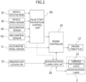
Figure 2] Figure 2 is a block diagram showing a control system for the refrigerator/freezer vehicle. - [
Figure 3] Figure 3 is a flowchart showing a false-start prevention control according to a first embodiment of the present invention. - [
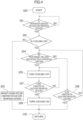
Figure 4] Figure 4 is a flowchart showing a false-start prevention control according to a second embodiment of the present invention. - [
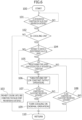
Figure 5] Figure 5 is a flowchart showing a false-start prevention control according to a third embodiment of the present invention. - [
Figure 6] Figure 6 is a flowchart showing a false-start prevention control according to a fourth embodiment of the present invention. - Hereinafter, embodiments of the present invention will be described in detail with reference to the drawings.
- In
Figure 1 , a refrigerator/freezer vehicle 1 includes a refrigerating/freezing chamber 2 at a vehicle body rear portion of a cab-over type truck that is equipped with aninternal combustion engine 12 on the lower side of a vehicle cabin. For example, the refrigerating/freezing chamber 2 is configured as a container having a heat insulation structure in which a heat insulation material is used, and includes an openable door at a rear portion, an openable door at a side surface, or an openable door at both a rear portion and at a side surface. - A freezing system of the refrigerating/freezing
chamber 2 includes acompressor 22 that is driven by the dynamic power of theengine 12, acondenser 23 andreceiver dryer 24 that are equipped at a lower portion of a side surface of a vehicle body rear portion, and anevaporator 25 that is disposed at a ceiling portion of the refrigerating/freezingchamber 2, and is configured to cool the chamber interior by joining them through pipes, circulating a refrigerant, and executing a freezing cycle (compression, condensation, expansion and evaporation). - The
compressor 22 to compress the refrigerant is configured such that an electromagnetic clutch is attached to a pulley that is driven through a belt by theengine 12, the on and off control of the electromagnetic clutch is performed by a refrigerating/freezingchamber control unit 20 based on a chamber interior temperature that is detected by a temperature sensor provided in the refrigerating/freezing chamber 2, and thereby, the actuation and non-actuation (cooling on and off) of thecompressor 22 is switched, so that the chamber interior is maintained in a predetermined temperature range. -
Figure 2 shows a control system for the refrigerator/freezer vehicle 1. When a cooling switch of an operation unit 21 (control panel) of the refrigerating/freezing chamber 2 is turned on in a state in which theengine 12 is actuated, the refrigerating/freezingchamber control unit 20 turns the electromagnetic clutch on to actuate thecompressor 22, based on the setting temperature and the chamber interior temperature, and actuates a fan motor of thecondenser 23 and a fan motor of theevaporator 25, so that the refrigerating/freezing chamber 2 enters an actuation state and the air within the chamber is cooled. - The refrigerator/
freezer vehicle 1 includes an electronic control throttle system configured such that the opening degree (throttle motor) of a throttle valve of theengine 12 is controlled by anengine controller 10 depending on the amount (torque demand) an accelerator pedal is depressed that is detected by anaccelerator pedal sensor 11. Theengine controller 10 acquires various detection values indicating the operating state of theengine 12, and the traveling state of the vehicle, in addition to the amount the accelerator pedal is depressed, and optimally maintains the operating state of theengine 12. - For example, even when idling, when the on-operation of the cooling switch of the refrigerating/
freezing chamber 2 is performed and thecompressor 22 is actuated, theengine controller 10 controls the throttle opening degree such that the output of theengine 12 is an output corresponding to the load of thecompressor 22, in response to the torque demand from the refrigerating/freezingchamber control unit 20. Furthermore, a torque demand value to be allocated to driver's accelerator operation (the accelerator pedal sensor 11) is reduced depending on a torque demand value to be allocated to the refrigerating/freezing chamber 2 (compressor 22), thereby, the output of theengine 12 is efficiently distributed for traveling and cooling. - The refrigerator/
freezer vehicle 1 having the above-described basic configuration includes a false-startprevention control unit 30 for executing a false-start prevention control. The false-startprevention control unit 30 acquires the distance to an obstacle that is detected by obstacle detection means 31, the vehicle speed that is detected by a vehicle speed sensor 41 (or a wheel speed sensor), and the amount the accelerator pedal is depressed that is detected by theaccelerator pedal sensor 11, and based on these, determines whether an intervention condition for the false-start prevention control (engine torque suppression control) is satisfied. - That is, it is determined that the intervention condition for the false-start prevention control is satisfied, in the case in which a predetermined accelerator depression amount or greater is detected by the
accelerator pedal sensor 11, in the state in which the vehicle speed detected by thevehicle speed sensor 41 is in a low speed range equal to or lower than a predetermined speed or the vehicle is stopped and in which an obstacle is detected by the obstacle detection means 31 within a predetermined distance in the movement direction. - In the case in which the intervention condition for the false-start prevention control is satisfied, the
engine controller 10 restricts the accelerator opening degree and suppresses the engine torque based on a torque suppression command of the false-startprevention control unit 30, regardless of the stepping amount (torque demand) of the accelerator pedal. - Other than the above information, the false-start
prevention control unit 30 acquires information such as the acceleration that is detected by anacceleration sensor 42, the inclination (road surface inclination) of the vehicle that is detected by aninclination sensor 43, and a selected gear stage of a transmission control unit (not shown). - For example, in the case in which the inclination is detected by the
inclination sensor 43, the torque-down amount necessary to be suppressed is adjusted depending on the inclination direction and the inclination degree. Furthermore, during the actuation of the false-start prevention control, in the case in which an acceleration in the rearward movement direction is detected by theacceleration sensor 42, although the selected gear stage is not a rearward movement, the determination of a slide-down is made, the torque-down amount is adjusted so as to be small, and a creep torque for preventing the slide-down is maintained. As theinclination sensor 43, inclination sensors, acceleration sensors, multiaxial inertia sensors and the like that detect the inclination of the refrigerator/freezer vehicle 1 in the front-rear direction based on the gravitational acceleration can be used. - Preferably, the obstacle detection means 31 should include a
forward obstacle sensor 31a that detects an obstacle positioned forward of the vehicle and arearward obstacle sensor 31b that detects an obstacle positioned rearward of the vehicle as shown inFigure 1 , and should be configured to selectively execute a false-start prevention control for the forward movement direction and a false-start prevention control for the rearward movement direction, depending on the selected gear stage information of the transmission control unit. - As the obstacle detection means 31, various sensors that can determine the existence or non-existence of the obstacle and the distance information about the obstacle, for example, an ultrasonic sensor, a millimeter wave radar and the like can be suitably used, or instead of, or in addition to them, a stereo camera and a LiDAR can be used.
- The false-start
prevention control unit 30 is configured as a computer (ECU) constituted by a ROM that contains control programs, setting data and the like for executing the above controls, a RAM that temporarily stores arithmetic processing results, a CPU that performs arithmetic processing, a communication I/F and the like, and can acquire each detection information through an in-vehicle network. - The refrigerator/
freezer vehicle 1 needs to drive thecompressor 22 at a high rotation, due to the setting temperature of the refrigerating/freezing chamber 2, or in a situation in which cooling capacity is required, for example, after the opening and closing of a door or immediately after a cooling switch on-operation, and therefore, the torque demand value from the refrigerating/freezingchamber control unit 20 to theengine controller 10 increases. Therefore, when the false-start prevention control (engine torque suppression control) is executed in a state in which the engine torque has decreased due to the load of thecompressor 22, there is risk that the torque-down amount of theengine 12 will be excessively large. - Hence, the false-start
prevention control unit 30 of the refrigerator/freezer vehicle 1 according to the present invention is configured to be set a constant value or zero as the torque demand value to be allocated to thecompressor 22 of the refrigerating/freezing chamber 1 in theengine controller 10, at the time when the intervention condition for the false-start prevention control is satisfied. Some embodiments of the improved false-start prevention control will be described below with reference to the drawings. -
Figure 3 is a flowchart showing a false-start prevention control according to a first embodiment. The false-start prevention control is started in a state in which theengine 12 of the refrigerator/freezer vehicle 1 is actuated (step 100), and the false-startprevention control unit 30 monitors the vehicle speed that is detected by the vehicle speed sensor 41 (or the wheel speed sensor), the distance to the obstacle that is detected by the obstacle detection means 31, and the amount the accelerator pedal is depressed that is detected by the accelerator pedal sensor 11 (step 101). - At the time when a predetermined accelerator depression amount or greater is detected in a state in which the vehicle speed is in the low speed range equal to, or lower than, the predetermined speed, or the vehicle is stopped, and the obstacle is detected within the predetermined distance in the movement direction, and when it is determined that the intervention condition for the false-start prevention control is satisfied (
step 101; YES), if thecompressor 22 of the refrigerating/freezingchamber 2 is in the stop state (cooling off) (step 102; NO), the actuation of thecompressor 22 is prohibited until an end condition for the false-start prevention control is satisfied (step 103). - On the other hand, if the
compressor 22 of the refrigerating/freezing chamber 2 is in the actuation state (cooling on) (step 102; YES) at the time when it is determined that the intervention condition for the false-start prevention control is satisfied, the refrigerating/freezingchamber control unit 20 disengages the electromagnetic clutch of thecompressor 22, and stops the compressor 22 (cooling off) (step 105). - At the same time, the
engine controller 10 sets zero as the torque demand value to be allocated to thecompressor 22. Then, theengine controller 10 decides the torque-down amount of theengine 12 by referring to the inclination degree that is detected by theinclination sensor 43, as necessary, and restricts the accelerator opening degree to suppress the engine torque. - For example, when it is determined in the false-start
prevention control unit 30 that the intervention condition for the false-start prevention control is satisfied, a false-start prevention control actuation flag is turned on, and theengine controller 10 sets zero as the torque demand value to be allocated to thecompressor 22, so that the refrigerating/freezingchamber control unit 20 stops thecompressor 22. Alternatively, when the false-start prevention control actuation flag is turned on, the refrigerating/freezingchamber control unit 20 stops thecompressor 22, and at the same time, sets zero as the torque demand to theengine controller 10. - The false-start
prevention control unit 30 continues to monitor the intervention condition for the false-start prevention control even during the actuation of the engine torque suppression control (false-start prevention control) by theengine controller 10, the torque demand value to be allocated to thecompressor 22 is maintained at zero while the false-start prevention control actuation flag is in the on-state, and the refrigerating/freezingchamber control unit 20 maintains thecompressor 22 in the stop state (cooling off). - Thereafter, in the case in which the intervention condition for the false-start prevention control is not satisfied and in which the end condition for the false-start prevention control is satisfied (step 107; YES), for example, in the case in which the driver returns the accelerator pedal, the false-start prevention control actuation flag is turned off, and the refrigerating/freezing
chamber control unit 20 engages the electromagnetic clutch and places thecompressor 22 into the actuation state (cooling on) (step 109). - By executing the above control, the
engine controller 10 can decide a proper torque-down amount based on the state of the vehicle, in a state in which there is no load of thecompressor 22, regardless of the actuation state of the refrigerating/freezingchamber 2 at the time of the actuation of the false-start prevention control, and can execute a precise false-start prevention control. Although the actuation of the refrigerating/freezingchamber 2 is stopped during the period, no great effect is exerted on the cooling state in the case of a short-time stop. There is an advantage in that it is possible to execute, at low cost, a control matching actual circumstances in which the occurrence frequency of the false-start prevention control is low but the priority is high. - It is allowable to adopt a configuration in which the electromagnetic clutch of the
compressor 22 is engaged after a lapse of a predetermined time (second predetermined time; about 1 minute) in the case in which the end condition for the false-start prevention control is satisfied (step 107; YES) after the intervention condition for the false-start prevention control is satisfied and the electromagnetic clutch of thecompressor 22 is disengaged. This configuration has an advantage in that the burden on the compressor is reduced and a long life can be achieved. -
Figure 4 is a flowchart showing a false-start prevention control according to a second embodiment. The basic flow is the same as that in the first embodiment, and therefore, modifications will be described below. - The above-described first embodiment shows a case in which the
compressor 22 of the refrigerating/freezingchamber 2 is immediately stopped (cooling off) when thecompressor 22 is actuated (cooling on) at the time when the intervention condition for the false-start prevention control is satisfied (step 102; YES). In the second embodiment shown inFigure 4 , after a lapse of a predetermined time (first predetermined time) from the satisfying of the intervention condition for the false-start prevention control (step 104; YES), theengine controller 10 sets zero as the torque demand value to be allocated to thecompressor 22, and the refrigerating/freezingchamber control unit 20 disengages the electromagnetic clutch of thecompressor 22 and stops (cooling off) the compressor 22 (step 105). - In this case, at the time when the intervention condition for the false-start prevention control is satisfied, the
engine controller 10 decides the torque-down amount while maintaining thecompressor 22 in the actuation state (accordingly in consideration of the torque demand (load) for the compressor 22), and executes the engine torque suppression control, so that the torque-down amount is small until the predetermined time lapses. - Thereafter, at such a timing (for example, 0.5 to 2 seconds) that the refrigerator/
freezer vehicle 1 does not collide with the obstacle (or the refrigerator/freezer vehicle 1 does not move over a wheel chock), zero is set as the torque demand value to be allocated to thecompressor 22, and the engine torque is further suppressed, resulting in the transition to a stronger false-start prevention control. - By this control, in the case in which the end condition for the false-start prevention control is satisfied (step 108; YES), for example, in the case in which the driver performs accelerator-off before the lapse of the predetermined time, the false-start prevention control is ended at that time point, and the refrigerating/freezing chamber 2 (compressor 22) is maintained in the actuation state (cooling on). Accordingly, there is an advantage in that it is possible to perform a practical false-start prevention while reducing the effects on the cooling performance of the refrigerating/freezing
chamber 2. -
Figure 5 is a flowchart showing a false-start prevention control according to a third embodiment. The basic flow is the same as that in the first embodiment, and therefore, modifications will be described below. - The above-described first embodiment shows a case in which the
compressor 22 of the refrigerating/freezingchamber 2 is stopped (cooling off) when thecompressor 22 is actuated (cooling on) at the time when the intervention condition for the false-start prevention control is satisfied (step 102; YES). In the third embodiment shown inFigure 5 , the engagement of the electromagnetic clutch of thecompressor 22 is maintained, and theengine controller 10 sets a constant value instead of zero, as the torque demand value to be allocated to thecompressor 22, so that the refrigerating/freezingchamber 2 transitions to a constant output operation (step 106). - In this case, at the time when the intervention condition for the false-start prevention control is satisfied, the
engine controller 10 decides the torque-down amount while maintaining thecompressor 22 in the actuation state (accordingly in consideration of the torque demand (load) of the compressor 22), and executes the engine torque suppression control, so that the torque-down amount is smaller compared to the case of the stop of thecompressor 22. - However, even when the cooling request is thereafter performed during the false-start prevention control because of the temperature change in the refrigerating/freezing
chamber 2 or the like, the torque demand value to be allocated to thecompressor 22 is maintained at the constant value, and therefore, the torque variation that is caused by the cooling request is avoided, so that it is possible to perform a stable false-start prevention control. - Furthermore, during the actuation of the false-start prevention control, the actuation of the
compressor 22 is continued even though thecompressor 22 is maintained at a low rotation, and therefore, there is an advantage in that a better cooling state of the refrigerating/freezingchamber 2 is maintained compared to the case of the stop of thecompressor 22. - Thereafter, in the case in which the end condition for the false-start prevention control is satisfied due to the accelerator-off by the driver or the like (step 107; YES), the false-start prevention control actuation flag is turned off, and the
engine controller 10 transitions to a normal operation in which the torque demand value is allocated to thecompressor 22 in accordance with the torque demand of the refrigerating/freezing chamber control unit 20 (step 109). -
Figure 6 is a flowchart showing a false-start prevention control according to a fourth embodiment. The basic flow is the same as that in the second embodiment shown inFigure 4 , and therefore, the changes will be described. - In the false-start prevention control according to the fourth embodiment, when the
compressor 22 of the refrigerating/freezingchamber 2 is actuated (cooling on) at the time when the intervention condition for the false-start prevention control is satisfied (step 102; YES), the control is switched depending on the distance to the obstacle that is detected by the obstacle detection means 31. - That is, when the distance to the obstacle is a predetermined value or greater (
step 104; YES), the measurement of a predetermined time (first predetermined time) is started after the intervention condition for the false-start prevention control is satisfied, and after a lapse of the predetermined time (step 105; YES), zero is set as the torque demand value to be allocated to thecompressor 22, to stop the compressor 22 (cooling off), or a constant value is set as the torque demand value to be allocated to thecompressor 22, to transition to the constant output operation (step 106). - In this case, at the time when the intervention condition for the false-start prevention control is satisfied, the
engine controller 10 decides the torque-down amount while maintaining thecompressor 22 in the actuation state (in consideration of the torque demand (load) of the compressor 22), and executes the engine torque suppression control, so that the torque-down amount is small until the predetermined time lapses. - Thereafter, at such a timing (for example, 0.5 to 2 seconds) that the refrigerator/
freezer vehicle 1 does not collide with the obstacle (or the refrigerator/freezer vehicle 1 does not move over a wheel chock), zero is set as the torque demand value to be allocated to thecompressor 22, and the engine torque is further suppressed, resulting in the transition to a stronger false-start prevention control. - Furthermore, in the case in which the end condition for the false-start prevention control is satisfied (step 108; YES), for example, in the case in which the driver performs accelerator-off before the lapse of the predetermined time, the false-start prevention control is ended, and the refrigerating/freezing chamber 2 (compressor 22) is maintained in the actuation state.
- On the other hand, when the distance to the obstacle is less than the predetermined value (
step 104; NO), immediately after the intervention condition for the false-start prevention control is satisfied, zero is set as the torque demand value to be allocated to thecompressor 22, to stop the compressor 22 (cooling off), or the constant value is set as the torque demand value to be allocated to thecompressor 22, to transition to the constant output operation (step 106). - By switching the control of the refrigerating/freezing
chamber 2 depending on the distance to the obstacle as described above, it is possible to avoid the collision with the obstacle due to the false-start, and to reduce the influence on the cooling performance of the refrigerating/freezingchamber 2. - The torque at the time of the freezing chamber actuation with the above predetermined time (first predetermined time) and at the time of the actuation of the false-start prevention control is set to such a high torque that the slide-down does not occur even by the influence of the freezing chamber actuation, and thereby, it is possible to avoid the
compressor 22 of the refrigerating/freezingchamber 2 from being immoderately stopped, or to avoid cold holding performance from being decreased. - Furthermore, it is allowable to adopt a configuration in which the above predetermined time (first predetermined time) is dynamically set depending on the distance to the obstacle that is detected by the obstacle detection means 31. That is, the above predetermined time (first predetermined time) is set so as to be longer as the distance to the obstacle is longer, and is set so as to be shorter as the distance to the obstacle is shorter, and thereby, there is an advantage in achieving both the false-start prevention performance and the cooling performance.
- Although some embodiments of the present invention have been described above, the present invention is not limited to the above-described embodiments, and further various modifications and changes are possible on the basis of the technical idea of the present invention.
-
- 1
- Refrigerator/freezer vehicle
- 2
- Refrigerating/freezing chamber
- 10
- Engine controller
- 11
- Accelerator pedal sensor
- 12
- Engine
- 20
- Refrigerating/freezing chamber control unit
- 21
- Operation unit
- 22
- Compressor
- 23
- Condenser
- 24
- Receiver drier
- 25
- Evaporator
- 30
- False-start prevention control unit
- 31
- Obstacle detection sensor
- 41
- Vehicle speed sensor
- 42
- Acceleration sensor
- 43
- Inclination sensor
Claims (6)
- A refrigerator/freezer vehicle comprising:an engine control unit to control an engine depending on torque demand; anda refrigerating/freezing chamber to perform cooling by a compressor that is actuated by output of the engine,the refrigerator/freezer vehicle having a function to suppress engine torque when an accelerator pedal is operated in a state in which an obstacle is detected within a predetermined distance in a movement direction at a predetermined low vehicle speed or lower, characterized in thatthe refrigerator/freezer vehicle is configured to set a constant value or zero as a torque demand value to be allocated to the compressor, at time of actuation of the engine torque suppression function.
- The refrigerator/freezer vehicle according to claim 1, wherein the refrigerator/freezer vehicle is configured to set the constant value or zero as the torque demand value to be allocated to the compressor, after a lapse of a first predetermined time from satisfaction of an intervention condition for the engine torque suppression function when the accelerator pedal is operated in the state in which the obstacle is detected within the predetermined distance in the movement direction at the predetermined low vehicle speed or lower.
- The refrigerator/freezer vehicle according to claim 2, wherein the first predetermined time is dynamically set depending on a distance to the obstacle, and is set so as to be longer as the distance to the obstacle is longer.
- The refrigerator/freezer vehicle according to any one of claims 1 to 3, wherein the compressor is stopped when zero is set as the torque demand value to be allocated to the compressor.
- The refrigerator/freezer vehicle according to claim 4, wherein the refrigerator/freezer vehicle is configured to engage the clutch after a lapse of a second predetermined time, when an end condition for the engine torque suppression function is satisfied after the stop of the compressor.
- The refrigerator/freezer vehicle according to any one of claims 1 to 5, wherein the refrigerator/freezer vehicle is configured to prohibit the actuation of the compressor until an end condition for the engine torque suppression function is satisfied, when the compressor is in a stop state at the time of the actuation of the engine torque suppression function.
Applications Claiming Priority (1)
| Application Number | Priority Date | Filing Date | Title |
|---|---|---|---|
| JP2022038358A JP7769911B2 (en) | 2022-03-11 | 2022-03-11 | Refrigerated/freezer truck |
Publications (2)
| Publication Number | Publication Date |
|---|---|
| EP4242027A1 true EP4242027A1 (en) | 2023-09-13 |
| EP4242027B1 EP4242027B1 (en) | 2025-10-29 |
Family
ID=84537838
Family Applications (1)
| Application Number | Title | Priority Date | Filing Date |
|---|---|---|---|
| EP22214332.3A Active EP4242027B1 (en) | 2022-03-11 | 2022-12-16 | Refrigerator/freezer vehicle |
Country Status (2)
| Country | Link |
|---|---|
| EP (1) | EP4242027B1 (en) |
| JP (1) | JP7769911B2 (en) |
Citations (5)
| Publication number | Priority date | Publication date | Assignee | Title |
|---|---|---|---|---|
| JP4199380B2 (en) | 1999-08-12 | 2008-12-17 | 東芝キヤリア株式会社 | Refrigeration equipment for refrigeration vehicles |
| EP2609314B1 (en) * | 2010-08-27 | 2014-09-10 | Robert Bosch GmbH | Power control arrangement for a drive motor of a motor vehicle |
| JP6075575B2 (en) * | 2015-03-02 | 2017-02-08 | マツダ株式会社 | Vehicle control device |
| DE102018119933A1 (en) * | 2017-08-25 | 2019-02-28 | Thermo King Corporation | Method and system for adaptive power engine control |
| EP3277985B1 (en) * | 2015-04-02 | 2021-03-17 | PSA Automobiles SA | Method for controlling a motor vehicle transmission |
Family Cites Families (5)
| Publication number | Priority date | Publication date | Assignee | Title |
|---|---|---|---|---|
| JPS61197734A (en) * | 1985-02-22 | 1986-09-02 | Toyota Motor Corp | Output torque control device for internal-combustion engine |
| JP2009078631A (en) * | 2007-09-25 | 2009-04-16 | Denso Corp | Air conditioning control system for vehicles |
| JP5169585B2 (en) * | 2008-07-30 | 2013-03-27 | 株式会社デンソー | Vehicle air conditioning and braking control device |
| JP6670465B2 (en) * | 2014-12-18 | 2020-03-25 | スズキ株式会社 | False start suppression device |
| JP6676900B2 (en) * | 2015-08-31 | 2020-04-08 | いすゞ自動車株式会社 | Driving support device and driving support method |
-
2022
- 2022-03-11 JP JP2022038358A patent/JP7769911B2/en active Active
- 2022-12-16 EP EP22214332.3A patent/EP4242027B1/en active Active
Patent Citations (5)
| Publication number | Priority date | Publication date | Assignee | Title |
|---|---|---|---|---|
| JP4199380B2 (en) | 1999-08-12 | 2008-12-17 | 東芝キヤリア株式会社 | Refrigeration equipment for refrigeration vehicles |
| EP2609314B1 (en) * | 2010-08-27 | 2014-09-10 | Robert Bosch GmbH | Power control arrangement for a drive motor of a motor vehicle |
| JP6075575B2 (en) * | 2015-03-02 | 2017-02-08 | マツダ株式会社 | Vehicle control device |
| EP3277985B1 (en) * | 2015-04-02 | 2021-03-17 | PSA Automobiles SA | Method for controlling a motor vehicle transmission |
| DE102018119933A1 (en) * | 2017-08-25 | 2019-02-28 | Thermo King Corporation | Method and system for adaptive power engine control |
Also Published As
| Publication number | Publication date |
|---|---|
| JP7769911B2 (en) | 2025-11-14 |
| JP2023132815A (en) | 2023-09-22 |
| EP4242027B1 (en) | 2025-10-29 |
Similar Documents
| Publication | Publication Date | Title |
|---|---|---|
| US5924296A (en) | Motor vehicle air-conditioning apparatus with engine speed control | |
| EP1995094B1 (en) | Vehicle air conditioning system | |
| US9981530B2 (en) | Device and method for controlling compressor of vehicles | |
| US8560202B2 (en) | Method and apparatus for improved climate control function in a vehicle employing engine stop/start technology | |
| US20110067419A1 (en) | Air-conditioning control device for vehicle | |
| JP5510100B2 (en) | Air conditioning control device for vehicles | |
| JP2004189175A (en) | Vehicle air conditioner | |
| EP1897712B1 (en) | Air-conditioning system for vehicle | |
| JP5012491B2 (en) | Control device for vehicle air conditioner and vehicle | |
| US6755032B1 (en) | Control method for a vehicle having an engine and an accessory device | |
| EP2537693A2 (en) | Vehicle air-conditioner control system | |
| JP5673048B2 (en) | Vehicle air conditioning control device and vehicle control device | |
| JP4697627B2 (en) | Compressor torque estimation device | |
| EP4242027B1 (en) | Refrigerator/freezer vehicle | |
| EP1854979A1 (en) | Abnormality detection device for vehicle | |
| JP2011189812A (en) | Control device for vehicle | |
| JP6747582B2 (en) | Vehicle air-conditioning control method and vehicle air-conditioning apparatus | |
| CN110608102A (en) | Vehicle control device | |
| US6691522B1 (en) | Controller for vehicle air conditioner | |
| JP4329487B2 (en) | Vehicle auxiliary engine controller | |
| US12187101B2 (en) | Vehicle air conditioner | |
| JP4613455B2 (en) | Vehicle cooling system | |
| JP2003285618A (en) | Vehicle air conditioner | |
| JP7644791B2 (en) | Vehicle equipment control device | |
| US20230219397A1 (en) | Vehicle control system |
Legal Events
| Date | Code | Title | Description |
|---|---|---|---|
| PUAI | Public reference made under article 153(3) epc to a published international application that has entered the european phase |
Free format text: ORIGINAL CODE: 0009012 |
|
| STAA | Information on the status of an ep patent application or granted ep patent |
Free format text: STATUS: REQUEST FOR EXAMINATION WAS MADE |
|
| 17P | Request for examination filed |
Effective date: 20221216 |
|
| AK | Designated contracting states |
Kind code of ref document: A1 Designated state(s): AL AT BE BG CH CY CZ DE DK EE ES FI FR GB GR HR HU IE IS IT LI LT LU LV MC ME MK MT NL NO PL PT RO RS SE SI SK SM TR |
|
| STAA | Information on the status of an ep patent application or granted ep patent |
Free format text: STATUS: EXAMINATION IS IN PROGRESS |
|
| 17Q | First examination report despatched |
Effective date: 20240814 |
|
| RIC1 | Information provided on ipc code assigned before grant |
Ipc: B60W 30/188 20120101ALI20250526BHEP Ipc: B60W 30/09 20120101ALI20250526BHEP Ipc: B60W 10/30 20060101ALI20250526BHEP Ipc: B60W 10/06 20060101ALI20250526BHEP Ipc: B60H 1/32 20060101AFI20250526BHEP |
|
| GRAP | Despatch of communication of intention to grant a patent |
Free format text: ORIGINAL CODE: EPIDOSNIGR1 |
|
| STAA | Information on the status of an ep patent application or granted ep patent |
Free format text: STATUS: GRANT OF PATENT IS INTENDED |
|
| INTG | Intention to grant announced |
Effective date: 20250703 |
|
| GRAS | Grant fee paid |
Free format text: ORIGINAL CODE: EPIDOSNIGR3 |
|
| GRAA | (expected) grant |
Free format text: ORIGINAL CODE: 0009210 |
|
| STAA | Information on the status of an ep patent application or granted ep patent |
Free format text: STATUS: THE PATENT HAS BEEN GRANTED |
|
| AK | Designated contracting states |
Kind code of ref document: B1 Designated state(s): AL AT BE BG CH CY CZ DE DK EE ES FI FR GB GR HR HU IE IS IT LI LT LU LV MC ME MK MT NL NO PL PT RO RS SE SI SK SM TR |
|
| REG | Reference to a national code |
Ref country code: CH Ref legal event code: F10 Free format text: ST27 STATUS EVENT CODE: U-0-0-F10-F00 (AS PROVIDED BY THE NATIONAL OFFICE) Effective date: 20251029 Ref country code: GB Ref legal event code: FG4D |
|
| REG | Reference to a national code |
Ref country code: DE Ref legal event code: R096 Ref document number: 602022023880 Country of ref document: DE |
|
| REG | Reference to a national code |
Ref country code: IE Ref legal event code: FG4D |
|
| PGFP | Annual fee paid to national office [announced via postgrant information from national office to epo] |
Ref country code: DE Payment date: 20251215 Year of fee payment: 4 |
|
| PGFP | Annual fee paid to national office [announced via postgrant information from national office to epo] |
Ref country code: AT Payment date: 20260113 Year of fee payment: 4 |
|
| PGFP | Annual fee paid to national office [announced via postgrant information from national office to epo] |
Ref country code: FR Payment date: 20251204 Year of fee payment: 4 |
|
| REG | Reference to a national code |
Ref country code: NL Ref legal event code: MP Effective date: 20251029 |
|
| PG25 | Lapsed in a contracting state [announced via postgrant information from national office to epo] |
Ref country code: ES Free format text: LAPSE BECAUSE OF FAILURE TO SUBMIT A TRANSLATION OF THE DESCRIPTION OR TO PAY THE FEE WITHIN THE PRESCRIBED TIME-LIMIT Effective date: 20251029 |
|
| REG | Reference to a national code |
Ref country code: LT Ref legal event code: MG9D |
|
| PG25 | Lapsed in a contracting state [announced via postgrant information from national office to epo] |
Ref country code: NO Free format text: LAPSE BECAUSE OF FAILURE TO SUBMIT A TRANSLATION OF THE DESCRIPTION OR TO PAY THE FEE WITHIN THE PRESCRIBED TIME-LIMIT Effective date: 20260129 |
|
| PG25 | Lapsed in a contracting state [announced via postgrant information from national office to epo] |
Ref country code: HR Free format text: LAPSE BECAUSE OF FAILURE TO SUBMIT A TRANSLATION OF THE DESCRIPTION OR TO PAY THE FEE WITHIN THE PRESCRIBED TIME-LIMIT Effective date: 20251029 Ref country code: AT Free format text: LAPSE BECAUSE OF FAILURE TO SUBMIT A TRANSLATION OF THE DESCRIPTION OR TO PAY THE FEE WITHIN THE PRESCRIBED TIME-LIMIT Effective date: 20251029 Ref country code: FI Free format text: LAPSE BECAUSE OF FAILURE TO SUBMIT A TRANSLATION OF THE DESCRIPTION OR TO PAY THE FEE WITHIN THE PRESCRIBED TIME-LIMIT Effective date: 20251029 |
|
| REG | Reference to a national code |
Ref country code: AT Ref legal event code: MK05 Ref document number: 1851190 Country of ref document: AT Kind code of ref document: T Effective date: 20251029 |
|
| PG25 | Lapsed in a contracting state [announced via postgrant information from national office to epo] |
Ref country code: NL Free format text: LAPSE BECAUSE OF FAILURE TO SUBMIT A TRANSLATION OF THE DESCRIPTION OR TO PAY THE FEE WITHIN THE PRESCRIBED TIME-LIMIT Effective date: 20251029 |
|
| PG25 | Lapsed in a contracting state [announced via postgrant information from national office to epo] |
Ref country code: RS Free format text: LAPSE BECAUSE OF FAILURE TO SUBMIT A TRANSLATION OF THE DESCRIPTION OR TO PAY THE FEE WITHIN THE PRESCRIBED TIME-LIMIT Effective date: 20260129 |
|
| PG25 | Lapsed in a contracting state [announced via postgrant information from national office to epo] |
Ref country code: IS Free format text: LAPSE BECAUSE OF FAILURE TO SUBMIT A TRANSLATION OF THE DESCRIPTION OR TO PAY THE FEE WITHIN THE PRESCRIBED TIME-LIMIT Effective date: 20260228 |
|
| PG25 | Lapsed in a contracting state [announced via postgrant information from national office to epo] |
Ref country code: PT Free format text: LAPSE BECAUSE OF FAILURE TO SUBMIT A TRANSLATION OF THE DESCRIPTION OR TO PAY THE FEE WITHIN THE PRESCRIBED TIME-LIMIT Effective date: 20260302 |
|
| PG25 | Lapsed in a contracting state [announced via postgrant information from national office to epo] |
Ref country code: PL Free format text: LAPSE BECAUSE OF FAILURE TO SUBMIT A TRANSLATION OF THE DESCRIPTION OR TO PAY THE FEE WITHIN THE PRESCRIBED TIME-LIMIT Effective date: 20251029 |
|
| PG25 | Lapsed in a contracting state [announced via postgrant information from national office to epo] |
Ref country code: LV Free format text: LAPSE BECAUSE OF FAILURE TO SUBMIT A TRANSLATION OF THE DESCRIPTION OR TO PAY THE FEE WITHIN THE PRESCRIBED TIME-LIMIT Effective date: 20251029 |
|
| PG25 | Lapsed in a contracting state [announced via postgrant information from national office to epo] |
Ref country code: BG Free format text: LAPSE BECAUSE OF FAILURE TO SUBMIT A TRANSLATION OF THE DESCRIPTION OR TO PAY THE FEE WITHIN THE PRESCRIBED TIME-LIMIT Effective date: 20251029 |