EP4242017B1 - Reifenmontagesystem und verfahren zur unterstützung der montage eines rades - Google Patents
Reifenmontagesystem und verfahren zur unterstützung der montage eines rades Download PDFInfo
- Publication number
- EP4242017B1 EP4242017B1 EP22161071.0A EP22161071A EP4242017B1 EP 4242017 B1 EP4242017 B1 EP 4242017B1 EP 22161071 A EP22161071 A EP 22161071A EP 4242017 B1 EP4242017 B1 EP 4242017B1
- Authority
- EP
- European Patent Office
- Prior art keywords
- tire
- rim
- location
- wheel
- air valve
- Prior art date
- Legal status (The legal status is an assumption and is not a legal conclusion. Google has not performed a legal analysis and makes no representation as to the accuracy of the status listed.)
- Active
Links
Images
Classifications
-
- B—PERFORMING OPERATIONS; TRANSPORTING
- B60—VEHICLES IN GENERAL
- B60C—VEHICLE TYRES; TYRE INFLATION; TYRE CHANGING; CONNECTING VALVES TO INFLATABLE ELASTIC BODIES IN GENERAL; DEVICES OR ARRANGEMENTS RELATED TO TYRES
- B60C25/00—Apparatus or tools adapted for mounting, removing or inspecting tyres
- B60C25/01—Apparatus or tools adapted for mounting, removing or inspecting tyres for removing tyres from or mounting tyres on wheels
- B60C25/05—Machines
-
- B—PERFORMING OPERATIONS; TRANSPORTING
- B60—VEHICLES IN GENERAL
- B60C—VEHICLE TYRES; TYRE INFLATION; TYRE CHANGING; CONNECTING VALVES TO INFLATABLE ELASTIC BODIES IN GENERAL; DEVICES OR ARRANGEMENTS RELATED TO TYRES
- B60C23/00—Devices for measuring, signalling, controlling, or distributing tyre pressure or temperature, specially adapted for mounting on vehicles; Arrangement of tyre inflating devices on vehicles, e.g. of pumps or of tanks; Tyre cooling arrangements
- B60C23/02—Signalling devices actuated by tyre pressure
- B60C23/04—Signalling devices actuated by tyre pressure mounted on the wheel or tyre
- B60C23/0408—Signalling devices actuated by tyre pressure mounted on the wheel or tyre transmitting the signals by non-mechanical means from the wheel or tyre to a vehicle body mounted receiver
- B60C23/0415—Automatically identifying wheel mounted units, e.g. after replacement or exchange of wheels
-
- B—PERFORMING OPERATIONS; TRANSPORTING
- B60—VEHICLES IN GENERAL
- B60C—VEHICLE TYRES; TYRE INFLATION; TYRE CHANGING; CONNECTING VALVES TO INFLATABLE ELASTIC BODIES IN GENERAL; DEVICES OR ARRANGEMENTS RELATED TO TYRES
- B60C23/00—Devices for measuring, signalling, controlling, or distributing tyre pressure or temperature, specially adapted for mounting on vehicles; Arrangement of tyre inflating devices on vehicles, e.g. of pumps or of tanks; Tyre cooling arrangements
- B60C23/02—Signalling devices actuated by tyre pressure
- B60C23/04—Signalling devices actuated by tyre pressure mounted on the wheel or tyre
- B60C23/0408—Signalling devices actuated by tyre pressure mounted on the wheel or tyre transmitting the signals by non-mechanical means from the wheel or tyre to a vehicle body mounted receiver
- B60C23/0422—Signalling devices actuated by tyre pressure mounted on the wheel or tyre transmitting the signals by non-mechanical means from the wheel or tyre to a vehicle body mounted receiver characterised by the type of signal transmission means
- B60C23/0433—Radio signals
- B60C23/0447—Wheel or tyre mounted circuits
-
- B—PERFORMING OPERATIONS; TRANSPORTING
- B60—VEHICLES IN GENERAL
- B60C—VEHICLE TYRES; TYRE INFLATION; TYRE CHANGING; CONNECTING VALVES TO INFLATABLE ELASTIC BODIES IN GENERAL; DEVICES OR ARRANGEMENTS RELATED TO TYRES
- B60C23/00—Devices for measuring, signalling, controlling, or distributing tyre pressure or temperature, specially adapted for mounting on vehicles; Arrangement of tyre inflating devices on vehicles, e.g. of pumps or of tanks; Tyre cooling arrangements
- B60C23/02—Signalling devices actuated by tyre pressure
- B60C23/04—Signalling devices actuated by tyre pressure mounted on the wheel or tyre
- B60C23/0408—Signalling devices actuated by tyre pressure mounted on the wheel or tyre transmitting the signals by non-mechanical means from the wheel or tyre to a vehicle body mounted receiver
- B60C23/0483—Wireless routers between wheel mounted transmitters and chassis mounted receivers
-
- B—PERFORMING OPERATIONS; TRANSPORTING
- B60—VEHICLES IN GENERAL
- B60C—VEHICLE TYRES; TYRE INFLATION; TYRE CHANGING; CONNECTING VALVES TO INFLATABLE ELASTIC BODIES IN GENERAL; DEVICES OR ARRANGEMENTS RELATED TO TYRES
- B60C2200/00—Tyres specially adapted for particular applications
- B60C2200/06—Tyres specially adapted for particular applications for heavy duty vehicles
Definitions
- the invention relates in general to tire fitting.
- the invention herein relates to a tire fitting system and a method performed by a tire fitting system for assisting in fitting a tire on a rim of a wheel prior to assembly of the wheel on a vehicle.
- the invention herein also relates to a computer program product for performing the method and computer program product carrier.
- each tire and/or rim of a wheel may also have one or more integrated or mounted Radio Frequency Identification, RFID, sensors, i.e. RFID tags, for enabling identification of the specific tire and/or specific rim of a wheel, which also employs radio frequency transmissions.
- RFID Radio Frequency Identification
- sensors i.e. RFID tags
- US 20040164140A1 describes an automotive vehicle service system incorporating an RFID interrogator to exchange data with one or more RFID transponders or tags associated with a vehicle undergoing service, or with a component of a vehicle undergoing service.
- WO 2012140367A2 describes a method of managing data between a RFID marker carried by a tyre and a sensor carried by a rim.
- US 20060238356A1 describes an RFID transmitter for tires and method of manufacture the same.
- JP 2003159918A describes a tire internal pressure sensor unit for a tire managing system that transmits a question sending signal to a transponder, receives tire intrinsic information including tire self-identification information, and transmits the information including the input tire intrinsic information to the central tire managing system provided at a vehicle body side at predetermined timing.
- the object is achieved by a method performed by a tire fitting system for assisting in fitting a tire on a rim of a wheel prior to assembly of the wheel on a vehicle.
- the method comprises determining a location of a Radio Frequency Identification, RFID, tag on the tire of the wheel.
- the method also comprise determining a location for an air valve on the rim of the wheel.
- the method further comprise the distance between the location of the RFID tag and the location for the air valve on the rim.
- the method comprise providing instructions for aligning the tire on the rim based on the determined distance between the location of the RFID tag and the location for the air valve.
- the object is achieved by a tire fitting system for fitting a tire on a rim of a wheel prior to assembly of the wheel on a vehicle.
- the tire fitting system comprise a processing circuitry configured determine a location of a RFID tag on the tire of the wheel.
- the processing circuitry is also configured to determine a location for an air valve on the rim of the wheel.
- the processing circuitry is further configured to determine the distance between the RFID tag and the location for the air valve on the rim.
- the processing circuitry is configured to provide instructions for aligning the tire on the rim based on the determined distance between the RFID tag and the location for the air valve on the rim.
- the object is achieved by a computer program comprising instructions which, when executed in a processing circuitry, cause the tire fitting system to carry out the methods described above.
- the object is achieved by a carrier containing any of the computer program products described above, wherein the carrier is one of an electronic signal, optical signal, radio signal, or computer-readable storage medium.
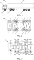
- the wheel 110 at the wheel position A of the truck or towing vehicle 101 of the vehicle 100 comprise at least one tire sensor 111
- the wheel 120 at the wheel position L of the truck or towing vehicle 101 of the vehicle 100 comprise at least one tire sensor 121
- each wheel 120a, 120b, 120c at the two front left wheel positions B, C, C' of the trailer unit 102 of the vehicle 100 comprise each at least one tire sensor 121a, 121b, 121c, respectively.
- each wheel 130a, 130b, 130c, 130d at the three back left wheel positions D, D', E, F of the trailer unit 102 of the vehicle 100 comprise each at least one tire sensor 131a, 131b, 131c, 131d, respectively.
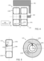
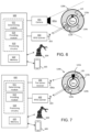
- Figs. 6-7 shows a schematic illustration of a tire fitting system 600 for assisting in fitting a tire 123b on a rim 124b of a wheel 120b prior to assembly of the wheel 120b on a vehicle 100 according to some embodiments.
- a power source e.g. a battery or main connection
- the processing circuitry 610 may further be arranged to communicate with the automation system 604 and/or display 605. Furthermore, the processing circuitry 310 may further comprise additional components, such as, for example, a determining module 611 and a providing module 612, each responsible for providing its functionality to support the embodiments described herein.
- the tire fitting system 600 or processing circuitry 610 is configured to, or may comprise the providing module 612 configured to, provide instructions for aligning the tire 123b on the rim 124b based on the determined distance between the location of the RFID tag 122b and the location for the air valve 125 on the rim 124b.
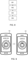
- Fig. 8 is an illustrated example of actions, steps or operations which may be performed a tire fitting system 600 described below with reference to Figs. 6-7 .
- the method may comprise the following actions, steps or operations.
- the tire fitting system 600 may, based on images of the tire 123b from the optical camera 601, determine the location of the RFID tag 122b on the tire 123b of the wheel 120b. This may be advantageous in cases when the tire 123b comprise a visual marker or indicator on the outside of the tire 123b indicating the location of the RFID tag 122b in the tire 123b.
- the tire fitting system 600 may, for example, use sequential scanning of areas of the tire 123b to determine the location of the RFID tag 122b on the tire 123b.
- the tire fitting system 600 may use the receiving direction and/or signal strength of the RFID transmission to determine the location of the RFID tag 122b on the tire 123b.
- the tire fitting system 600 determines the distance between the location of RFID tag 122b and the location for the air valve 125 on the rim 124b. This means that the tire fitting system 600 may determine if, and may also how, the tire 123b or the rim 124b should be repositioned relative to each other in order to ensure an advantageous location of the RFID tag 122b.
- the tire fitting system 600 may also determine that no repositioning or alignment of the tire 123b or rim 124b is necessary.
- the tire fitting system 600 After determining the distance in Action 803, the tire fitting system 600 provides instructions for aligning the tire 123b on the rim 124b based on the determined distance between the RFID tag 122b and the location for the air valve 125 on the rim 124b. In other words, the tire fitting system 600 may determine and provide instructions on how the tire 123b and/or the rim 124b should be repositioned or aligned relative to each other in order to ensure a favorable distance between the RFID tag 122b and the location for the air valve 125 on the rim 124b, i.e. a distance that is shorter than a determined threshold value.
- the tire fitting system 600 may control information being displayed on the display 605 such that the information persistently indicates how the tire 123b and/or the rim 124b should be aligned in regards to each other during the alignment or repositioning of the tire 123b and/or the rim 124b. This is exemplified by the display 605 in Fig. 9 (left). Furthermore, in some embodiments, the tire fitting system 600 may display information indicating that the alignment of the tire 123b on the rim 124b of the wheel 120b is complete on the display 605 when the distance between the location of the RFID tag 122b and the location for the air valve 125 is at or below the determined threshold level.
- the tire fitting system 600 may control information being displayed on the display 605 such that the information indicates when a proper alignment of the tire 123b and the rim 124b has been achieved. This is exemplified by the display 605 in Fig. 9 (right).
Landscapes
- Engineering & Computer Science (AREA)
- Mechanical Engineering (AREA)
- Computer Networks & Wireless Communication (AREA)
- Measuring Fluid Pressure (AREA)
Claims (16)
- Verfahren, durchgeführt von einem Reifenmontagesystem (600) zum Unterstützen beim Montieren eines Reifens (123b) auf eine Felge (124b) eines Rads (120b) vor Montage des Rads (120b) an einem Fahrzeug (100), wobei das Verfahren Folgendes umfa4rvsst:Bestimmen (701) einer Position eines Funkfrequenzidentifizierungs-Tags, RFID-Tags (122b), auf dem Reifen (123b) des Rads (120b);Bestimmen (702) einer Position für ein Luftventil (125) auf der Felge (124b) des Rads (120b);Bestimmen (703) des Abstands zwischen der Position des RFID-Tags (122b) und der Position für das Luftventil (125) auf der Felge (124b); undBereitstellen (704) von Anweisungen zum Ausrichten des Reifens (123b) auf der Felge (124b) basierend auf dem bestimmten Abstand zwischen der Position des RFID-Tags (122b) und der Position für das Luftventil (125) auf der Felge (124b).
- Verfahren nach Anspruch 1, wobei die Anweisungen an ein Automatisierungssystem (604) bereitgestellt werden, das dazu angeordnet ist, den Reifen (123b) physisch auf die Felge (124b) des Rads (120b) zu montieren.
- Verfahren nach Anspruch 1, wobei das Bereitstellen (704) Anzeigen der Anweisungen zum Ausrichten des Reifens (123b) auf der Felge (124b) des Rads (120b) auf einer Anzeige (605) umfasst.
- Verfahren nach Anspruch 3, ferner umfassend das Anzeigen der Anweisungen zum Ausrichten des Reifens (123b) auf der Felge (124b) des Rads (120b) auf der Anzeige (605), bis der Abstand zwischen der Position des RFID-Tags (122b) und der Position für das Luftventil (125) an oder unterhalb eines bestimmten Schwellenwertniveaus liegt.
- Verfahren nach Anspruch 3 oder 4, ferner umfassend Anzeigen von Informationen auf der Anzeige (605), die angeben, dass die Ausrichtung des Reifens (123b) auf der Felge (124b) des Rads (120b) abgeschlossen ist, wenn der Abstand zwischen der Position des RFID-Tags (122b) und der Position für das Luftventil (125) an oder unterhalb des bestimmten Schwellenwertniveaus liegt.
- Verfahren nach einem der Ansprüche 1-5, ferner umfassend das Bestimmen der Position des RFID-Tags (122b) auf dem Reifen (123b) des Rads (120b) durch Durchführen einer Bildverarbeitung an Bildern des Reifens (123b) von der optischen Kamera (601) oder durch Verwenden eines RFID-Scangeräts (602).
- Verfahren nach einem der Ansprüche 1-6, ferner umfassend das Bestimmen der Position für ein Luftventil (125) auf der Felge (124b) des Rads (120b) durch Durchführen einer Bildverarbeitung an Bildern der Felge (124b) von einer optischen Kamera (601) oder durch Verwenden eines Reifensensorempfängers (606).
- Reifenmontagesystem (600) zum Unterstützen beim Montieren eines Reifens (123b) auf eine Felge (124b) eines Rads (120b) vor Montage des Rads (120b) an einem Fahrzeug (100), wobei das Reifenmontagesystem (600) eine Verarbeitungsschaltung (610) umfasst, die zu Folgendem konfiguriert ist:
Bestimmen einer Position eines Funkfrequenzidentifizierungs-Tags, RFID-Tags (122b), auf dem Reifen (123b) des Rads (120b), Bestimmen einer Position für ein Luftventil (125) auf der Felge (124b) des Rads (120b), Bestimmen des Abstands zwischen der Position des RFID-Tags (122b) und der Position für das Luftventil (125) auf der Felge (124b) und Bereitstellen von Anweisungen zum Ausrichten des Reifens (123b) auf der Felge (124b) basierend auf dem bestimmten Abstand zwischen der Position des RFID-Tags (122b) und der Position für das Luftventil (125) auf der Felge (124b). - Reifenmontagesystem (600) nach Anspruch 8, wobei die Verarbeitungsschaltung (610) ferner dazu konfiguriert ist, die Anweisungen an ein Automatisierungssystem bereitzustellen, das dazu angeordnet ist, den Reifen (123b) physisch auf die Felge (124b) des Rads (120b) zu montieren.
- Reifenmontagesystem (600) nach Anspruch 8, wobei die Verarbeitungsschaltung (610) ferner dazu konfiguriert ist, die Anweisungen zum Ausrichten des Reifens (123b) auf der Felge (124b) auf einer Anzeige (605) anzuzeigen.
- Reifenmontagesystem (600) nach Anspruch 10, wobei die Verarbeitungsschaltung (610) ferner dazu konfiguriert ist, die Anweisungen zum Ausrichten des Reifens (123b) auf der Felge (124b) des Rads (120b) auf der Anzeige (605) anzuzeigen, bis der Abstand zwischen der Position des RFID-Tags (122b) und der Position für das Luftventil (125) an oder unterhalb eines bestimmten Schwellenwertniveaus liegt.
- Reifenmontagesystem (600) nach Anspruch 10 oder 11, wobei die Verarbeitungsschaltung (610) ferner dazu konfiguriert ist, Informationen auf der Anzeige (605) anzuzeigen, die angeben, dass die Ausrichtung des Reifens (123b) auf der Felge (124b) des Rads (120b) abgeschlossen ist, wenn der Abstand zwischen der Position des RFID-Tags (122b) und der Position für das Luftventil (125) an oder unterhalb des bestimmten Schwellenwertniveaus liegt.
- Reifenmontagesystem (600) nach einem der Ansprüche 8-12, wobei die Verarbeitungsschaltung (610) ferner dazu konfiguriert ist, die Position des RFID-Tags (122b) auf dem Reifen (123b) des Rads (120b) durch Durchführen einer Bildverarbeitung an Bildern des Reifens (123b) von der optischen Kamera (601) oder durch Verwenden eines RFID-Scangeräts (602) zu bestimmen.
- Reifenmontagesystem (600) nach einem der Ansprüche 8-13, wobei die Verarbeitungsschaltung (610) ferner dazu konfiguriert ist, die Position für ein Luftventil (125) auf der Felge (124b) des Rads (120b) durch Durchführen einer Bildverarbeitung an Bildern der Felge (124b) von einer optischen Kamera (601) oder durch Verwenden eines Reifensensorempfängers (606) zu bestimmen.
- Computerprogrammprodukt, umfassend Programmcodemittel zum Durchführen der Schritte nach einem der Ansprüche 1-7, wenn das Programm auf einem Reifenmontagesystem (600) nach einem der Ansprüche 8-14 ausgeführt wird.
- Computerprogrammträger, der ein Computerprogramm nach Anspruch 15 trägt, wobei der Computerprogrammträger eines von einem elektronischen Signal, optischen Signal, Funksignal oder einem computerlesbaren Speichermedium ist.
Priority Applications (2)
| Application Number | Priority Date | Filing Date | Title |
|---|---|---|---|
| EP22161071.0A EP4242017B1 (de) | 2022-03-09 | 2022-03-09 | Reifenmontagesystem und verfahren zur unterstützung der montage eines rades |
| US18/178,936 US12103339B2 (en) | 2022-03-09 | 2023-03-06 | Tire fitting system and method therein for assisting in fitting a wheel |
Applications Claiming Priority (1)
| Application Number | Priority Date | Filing Date | Title |
|---|---|---|---|
| EP22161071.0A EP4242017B1 (de) | 2022-03-09 | 2022-03-09 | Reifenmontagesystem und verfahren zur unterstützung der montage eines rades |
Publications (3)
| Publication Number | Publication Date |
|---|---|
| EP4242017A1 EP4242017A1 (de) | 2023-09-13 |
| EP4242017C0 EP4242017C0 (de) | 2025-04-09 |
| EP4242017B1 true EP4242017B1 (de) | 2025-04-09 |
Family
ID=80685192
Family Applications (1)
| Application Number | Title | Priority Date | Filing Date |
|---|---|---|---|
| EP22161071.0A Active EP4242017B1 (de) | 2022-03-09 | 2022-03-09 | Reifenmontagesystem und verfahren zur unterstützung der montage eines rades |
Country Status (2)
| Country | Link |
|---|---|
| US (1) | US12103339B2 (de) |
| EP (1) | EP4242017B1 (de) |
Families Citing this family (2)
| Publication number | Priority date | Publication date | Assignee | Title |
|---|---|---|---|---|
| EP4242017B1 (de) * | 2022-03-09 | 2025-04-09 | Volvo Truck Corporation | Reifenmontagesystem und verfahren zur unterstützung der montage eines rades |
| EP4424528A1 (de) * | 2023-02-28 | 2024-09-04 | Volvo Truck Corporation | Sensorlokalisierung unter verwendung eines montagelinienwerkzeugs |
Family Cites Families (14)
| Publication number | Priority date | Publication date | Assignee | Title |
|---|---|---|---|---|
| US20020116992A1 (en) * | 2001-02-26 | 2002-08-29 | Trw Inc. | System and method for monitoring wear of a vehicle component |
| JP3971918B2 (ja) * | 2001-11-28 | 2007-09-05 | 株式会社ブリヂストン | タイヤ内圧センサユニット、リム組立体、タイヤ、および、タイヤ管理システム |
| JP3661670B2 (ja) * | 2002-08-26 | 2005-06-15 | 株式会社デンソー | タイヤ空気圧監視システム、タイヤ空気圧監視装置、及びタイヤ空気圧監視プログラム |
| US20040084517A1 (en) * | 2002-11-05 | 2004-05-06 | Glen Harm | Method and apparatus for writing information to a tire pressure monitoring sensor |
| US6822582B2 (en) * | 2003-02-25 | 2004-11-23 | Hunter Engineering Company | Radio frequency identification automotive service systems |
| US7404427B2 (en) * | 2005-02-02 | 2008-07-29 | Hunter Engineering Company | Vehicle tire changer with integrated detector for tire pressure sensors |
| CN101164195B (zh) * | 2005-04-26 | 2015-05-13 | 库珀轮胎和橡胶公司 | 用于轮胎的射频识别装置发射机及其制造方法 |
| US7348878B2 (en) | 2005-09-29 | 2008-03-25 | International Truck Intellectual Property Company, Llc | Tire pressure monitoring system with permanent tire identification |
| FR2974210B1 (fr) * | 2011-04-12 | 2014-07-18 | Michelin Soc Tech | Procede de gestion de donnees entre un marqueur rfid porte par un pneumatique et un capteur porte par une jante |
| US9248709B2 (en) * | 2013-06-13 | 2016-02-02 | Infineon Technologies Ag | RFID-tag, a TPMS device, a tire, a receiver device and a method for providing information related to identification of a tire |
| US20160129734A1 (en) * | 2014-11-06 | 2016-05-12 | The Goodyear Tire & Rubber Company | Mobile-phone based data processing system |
| US9418492B2 (en) * | 2014-11-06 | 2016-08-16 | The Goodyear Tire & Rubber Company | Mobile phone enabled data processing system |
| US10919348B2 (en) | 2018-09-05 | 2021-02-16 | The Goodyear Tire & Rubber Company | Tire with RFID locator |
| EP4242017B1 (de) * | 2022-03-09 | 2025-04-09 | Volvo Truck Corporation | Reifenmontagesystem und verfahren zur unterstützung der montage eines rades |
-
2022
- 2022-03-09 EP EP22161071.0A patent/EP4242017B1/de active Active
-
2023
- 2023-03-06 US US18/178,936 patent/US12103339B2/en active Active
Also Published As
| Publication number | Publication date |
|---|---|
| EP4242017C0 (de) | 2025-04-09 |
| EP4242017A1 (de) | 2023-09-13 |
| US12103339B2 (en) | 2024-10-01 |
| US20230286335A1 (en) | 2023-09-14 |
Similar Documents
| Publication | Publication Date | Title |
|---|---|---|
| US6581449B1 (en) | Low pressure warning system for pneumatic tires with RF tags and monitors for each tire | |
| EP4101662B1 (de) | System und verfahren darin zur bestimmung einer position eines reifensensors auf einem fahrgestell eines fahrzeugs | |
| US7990257B2 (en) | Tire localization system | |
| US7104438B2 (en) | Method of integrating tire identification into a vehicle information system | |
| EP4242017B1 (de) | Reifenmontagesystem und verfahren zur unterstützung der montage eines rades | |
| RU2567130C2 (ru) | Способ и система определения расположения шин транспортного средства со сдвоенными задними шинами | |
| CN105415985A (zh) | 轮胎胎面磨损传感器系统 | |
| CN101391563A (zh) | 轮胎充气压力检测装置 | |
| US11987080B2 (en) | Portable electronic device and method therein for locating tire sensors on a vehicle | |
| US12319099B2 (en) | Tire fitting system and a method therein for sensor discrimination | |
| US6717512B2 (en) | Method and device for verifying the compatibility of the components of a wheel | |
| EP1220756A1 (de) | Reifenunterdruck- warneinrichtung | |
| US12434514B2 (en) | Tire sensor pairing system and method for pairing tire sensors | |
| EP4578768A1 (de) | System und verfahren darin zur lokalisierung eines montagelinienwerkzeugs in bezug auf mindestens eine achse eines fahrzeugs | |
| EP4306338A1 (de) | Bodenobjektsystem, elektronisches steuergerät und verfahren darin zur lokalisierung von reifensensoren auf einem fahrzeug | |
| EP4570533A1 (de) | Radüberwachungssystem und -verfahren | |
| US12485710B2 (en) | Electronic control unit (ECU) and method therein for monitoring tire sensors in a vehicle | |
| WO2024218182A1 (en) | An integrated sensor communication hub for a vehicle |
Legal Events
| Date | Code | Title | Description |
|---|---|---|---|
| PUAI | Public reference made under article 153(3) epc to a published international application that has entered the european phase |
Free format text: ORIGINAL CODE: 0009012 |
|
| STAA | Information on the status of an ep patent application or granted ep patent |
Free format text: STATUS: THE APPLICATION HAS BEEN PUBLISHED |
|
| AK | Designated contracting states |
Kind code of ref document: A1 Designated state(s): AL AT BE BG CH CY CZ DE DK EE ES FI FR GB GR HR HU IE IS IT LI LT LU LV MC MK MT NL NO PL PT RO RS SE SI SK SM TR |
|
| STAA | Information on the status of an ep patent application or granted ep patent |
Free format text: STATUS: REQUEST FOR EXAMINATION WAS MADE |
|
| 17P | Request for examination filed |
Effective date: 20231219 |
|
| RBV | Designated contracting states (corrected) |
Designated state(s): AL AT BE BG CH CY CZ DE DK EE ES FI FR GB GR HR HU IE IS IT LI LT LU LV MC MK MT NL NO PL PT RO RS SE SI SK SM TR |
|
| GRAP | Despatch of communication of intention to grant a patent |
Free format text: ORIGINAL CODE: EPIDOSNIGR1 |
|
| STAA | Information on the status of an ep patent application or granted ep patent |
Free format text: STATUS: GRANT OF PATENT IS INTENDED |
|
| RIC1 | Information provided on ipc code assigned before grant |
Ipc: B60C 23/04 20060101ALI20241113BHEP Ipc: B60C 25/05 20060101AFI20241113BHEP |
|
| INTG | Intention to grant announced |
Effective date: 20241216 |
|
| GRAS | Grant fee paid |
Free format text: ORIGINAL CODE: EPIDOSNIGR3 |
|
| GRAA | (expected) grant |
Free format text: ORIGINAL CODE: 0009210 |
|
| STAA | Information on the status of an ep patent application or granted ep patent |
Free format text: STATUS: THE PATENT HAS BEEN GRANTED |
|
| AK | Designated contracting states |
Kind code of ref document: B1 Designated state(s): AL AT BE BG CH CY CZ DE DK EE ES FI FR GB GR HR HU IE IS IT LI LT LU LV MC MK MT NL NO PL PT RO RS SE SI SK SM TR |
|
| REG | Reference to a national code |
Ref country code: GB Ref legal event code: FG4D |
|
| REG | Reference to a national code |
Ref country code: CH Ref legal event code: EP |
|
| REG | Reference to a national code |
Ref country code: DE Ref legal event code: R096 Ref document number: 602022012762 Country of ref document: DE |
|
| REG | Reference to a national code |
Ref country code: IE Ref legal event code: FG4D |
|
| U01 | Request for unitary effect filed |
Effective date: 20250424 |
|
| U07 | Unitary effect registered |
Designated state(s): AT BE BG DE DK EE FI FR IT LT LU LV MT NL PT RO SE SI Effective date: 20250430 |
|
| PG25 | Lapsed in a contracting state [announced via postgrant information from national office to epo] |
Ref country code: ES Free format text: LAPSE BECAUSE OF FAILURE TO SUBMIT A TRANSLATION OF THE DESCRIPTION OR TO PAY THE FEE WITHIN THE PRESCRIBED TIME-LIMIT Effective date: 20250409 |
|
| PG25 | Lapsed in a contracting state [announced via postgrant information from national office to epo] |
Ref country code: NO Free format text: LAPSE BECAUSE OF FAILURE TO SUBMIT A TRANSLATION OF THE DESCRIPTION OR TO PAY THE FEE WITHIN THE PRESCRIBED TIME-LIMIT Effective date: 20250709 Ref country code: GR Free format text: LAPSE BECAUSE OF FAILURE TO SUBMIT A TRANSLATION OF THE DESCRIPTION OR TO PAY THE FEE WITHIN THE PRESCRIBED TIME-LIMIT Effective date: 20250710 |
|
| PG25 | Lapsed in a contracting state [announced via postgrant information from national office to epo] |
Ref country code: PL Free format text: LAPSE BECAUSE OF FAILURE TO SUBMIT A TRANSLATION OF THE DESCRIPTION OR TO PAY THE FEE WITHIN THE PRESCRIBED TIME-LIMIT Effective date: 20250409 |
|
| PG25 | Lapsed in a contracting state [announced via postgrant information from national office to epo] |
Ref country code: HR Free format text: LAPSE BECAUSE OF FAILURE TO SUBMIT A TRANSLATION OF THE DESCRIPTION OR TO PAY THE FEE WITHIN THE PRESCRIBED TIME-LIMIT Effective date: 20250409 |
|
| PG25 | Lapsed in a contracting state [announced via postgrant information from national office to epo] |
Ref country code: RS Free format text: LAPSE BECAUSE OF FAILURE TO SUBMIT A TRANSLATION OF THE DESCRIPTION OR TO PAY THE FEE WITHIN THE PRESCRIBED TIME-LIMIT Effective date: 20250709 |
|
| PG25 | Lapsed in a contracting state [announced via postgrant information from national office to epo] |
Ref country code: IS Free format text: LAPSE BECAUSE OF FAILURE TO SUBMIT A TRANSLATION OF THE DESCRIPTION OR TO PAY THE FEE WITHIN THE PRESCRIBED TIME-LIMIT Effective date: 20250809 |
|
| PG25 | Lapsed in a contracting state [announced via postgrant information from national office to epo] |
Ref country code: SM Free format text: LAPSE BECAUSE OF FAILURE TO SUBMIT A TRANSLATION OF THE DESCRIPTION OR TO PAY THE FEE WITHIN THE PRESCRIBED TIME-LIMIT Effective date: 20250409 |
|
| PG25 | Lapsed in a contracting state [announced via postgrant information from national office to epo] |
Ref country code: CZ Free format text: LAPSE BECAUSE OF FAILURE TO SUBMIT A TRANSLATION OF THE DESCRIPTION OR TO PAY THE FEE WITHIN THE PRESCRIBED TIME-LIMIT Effective date: 20250409 |
|
| PG25 | Lapsed in a contracting state [announced via postgrant information from national office to epo] |
Ref country code: SK Free format text: LAPSE BECAUSE OF FAILURE TO SUBMIT A TRANSLATION OF THE DESCRIPTION OR TO PAY THE FEE WITHIN THE PRESCRIBED TIME-LIMIT Effective date: 20250409 |
|
| PLBE | No opposition filed within time limit |
Free format text: ORIGINAL CODE: 0009261 |
|
| STAA | Information on the status of an ep patent application or granted ep patent |
Free format text: STATUS: NO OPPOSITION FILED WITHIN TIME LIMIT |