EP4242014A2 - Tire wear prediction system, tire wear prediction program, tire wear prediction method, and data structure - Google Patents
Tire wear prediction system, tire wear prediction program, tire wear prediction method, and data structure Download PDFInfo
- Publication number
- EP4242014A2 EP4242014A2 EP23179071.8A EP23179071A EP4242014A2 EP 4242014 A2 EP4242014 A2 EP 4242014A2 EP 23179071 A EP23179071 A EP 23179071A EP 4242014 A2 EP4242014 A2 EP 4242014A2
- Authority
- EP
- European Patent Office
- Prior art keywords
- tire
- wear
- state
- wear state
- prediction
- Prior art date
- Legal status (The legal status is an assumption and is not a legal conclusion. Google has not performed a legal analysis and makes no representation as to the accuracy of the status listed.)
- Granted
Links
Images


Classifications
-
- B—PERFORMING OPERATIONS; TRANSPORTING
- B60—VEHICLES IN GENERAL
- B60C—VEHICLE TYRES; TYRE INFLATION; TYRE CHANGING; CONNECTING VALVES TO INFLATABLE ELASTIC BODIES IN GENERAL; DEVICES OR ARRANGEMENTS RELATED TO TYRES
- B60C11/00—Tyre tread bands; Tread patterns; Anti-skid inserts
- B60C11/24—Wear-indicating arrangements
- B60C11/246—Tread wear monitoring systems
-
- B—PERFORMING OPERATIONS; TRANSPORTING
- B60—VEHICLES IN GENERAL
- B60C—VEHICLE TYRES; TYRE INFLATION; TYRE CHANGING; CONNECTING VALVES TO INFLATABLE ELASTIC BODIES IN GENERAL; DEVICES OR ARRANGEMENTS RELATED TO TYRES
- B60C23/00—Devices for measuring, signalling, controlling, or distributing tyre pressure or temperature, specially adapted for mounting on vehicles; Arrangement of tyre inflating devices on vehicles, e.g. of pumps or of tanks; Tyre cooling arrangements
- B60C23/02—Signalling devices actuated by tyre pressure
- B60C23/04—Signalling devices actuated by tyre pressure mounted on the wheel or tyre
- B60C23/0408—Signalling devices actuated by tyre pressure mounted on the wheel or tyre transmitting the signals by non-mechanical means from the wheel or tyre to a vehicle body mounted receiver
-
- B—PERFORMING OPERATIONS; TRANSPORTING
- B60—VEHICLES IN GENERAL
- B60C—VEHICLE TYRES; TYRE INFLATION; TYRE CHANGING; CONNECTING VALVES TO INFLATABLE ELASTIC BODIES IN GENERAL; DEVICES OR ARRANGEMENTS RELATED TO TYRES
- B60C23/00—Devices for measuring, signalling, controlling, or distributing tyre pressure or temperature, specially adapted for mounting on vehicles; Arrangement of tyre inflating devices on vehicles, e.g. of pumps or of tanks; Tyre cooling arrangements
- B60C23/02—Signalling devices actuated by tyre pressure
- B60C23/04—Signalling devices actuated by tyre pressure mounted on the wheel or tyre
- B60C23/0408—Signalling devices actuated by tyre pressure mounted on the wheel or tyre transmitting the signals by non-mechanical means from the wheel or tyre to a vehicle body mounted receiver
- B60C23/0415—Automatically identifying wheel mounted units, e.g. after replacement or exchange of wheels
-
- B—PERFORMING OPERATIONS; TRANSPORTING
- B60—VEHICLES IN GENERAL
- B60C—VEHICLE TYRES; TYRE INFLATION; TYRE CHANGING; CONNECTING VALVES TO INFLATABLE ELASTIC BODIES IN GENERAL; DEVICES OR ARRANGEMENTS RELATED TO TYRES
- B60C23/00—Devices for measuring, signalling, controlling, or distributing tyre pressure or temperature, specially adapted for mounting on vehicles; Arrangement of tyre inflating devices on vehicles, e.g. of pumps or of tanks; Tyre cooling arrangements
- B60C23/02—Signalling devices actuated by tyre pressure
- B60C23/04—Signalling devices actuated by tyre pressure mounted on the wheel or tyre
- B60C23/0408—Signalling devices actuated by tyre pressure mounted on the wheel or tyre transmitting the signals by non-mechanical means from the wheel or tyre to a vehicle body mounted receiver
- B60C23/0415—Automatically identifying wheel mounted units, e.g. after replacement or exchange of wheels
- B60C23/0416—Automatically identifying wheel mounted units, e.g. after replacement or exchange of wheels allocating a corresponding wheel position on vehicle, e.g. front/left or rear/right
-
- G—PHYSICS
- G01—MEASURING; TESTING
- G01M—TESTING STATIC OR DYNAMIC BALANCE OF MACHINES OR STRUCTURES; TESTING OF STRUCTURES OR APPARATUS, NOT OTHERWISE PROVIDED FOR
- G01M17/00—Testing of vehicles
- G01M17/007—Wheeled or endless-tracked vehicles
- G01M17/02—Tyres
Definitions
- the present invention relates to a tire wear prediction system and a tire wear prediction program for predicting the wear state of a tire mounted on a vehicle.
- the present application is a divisional application of EP19798846.2 .
- Patent Literature 1 it is possible to predict the wear state of a tire mounted on a vehicle, that is, the amount of wear of the tire with a certain degree of accuracy.
- the following problems occur in the actual operating environment of the vehicle.
- the position of a wheel mounted is generally rotated (tire rotation) during the use.
- the method for predicting the wear state of the tire predicts the wear state from the new tire mounted at the predetermined wheel position, when the tire rotation is performed as this manner, it becomes difficult to accurately predict the wear amount of the tire.
- the tire is often replaced with another tire in stock, specifically, a new or used tire, or a tire of a different brand or type (Studless tires, etc.) at the time of tire rotation, and it becomes more difficult to predict the wear amount of the heavy load tire.
- an object of the present invention is to provide a tire wear prediction system, a tire wear prediction program, a tire wear prediction method and a data structure capable of accurately predicting the wear state of a tire even when the tire mounted on a vehicle is rotated or replaced with another tire.
- One aspect of the present invention is a tire wear prediction system (Tire wear prediction system 100) including a wear prediction unit (Wear prediction unit 110) for predicting a wear state of a tire mounted at a predetermined wheel position of a vehicle (Bus 10) based on a traveling state of the vehicle, a change history acquisition unit (Change history acquisition unit 120) for acquiring a change history including rotation of the wheel position on which the tire is mounted or a content of replacement with another tire, and a wear state correction unit (Wear state correction unit 140) for correcting a reference of the wear state of the tire predicted by the wear prediction unit based on the change history.
- the wear prediction unit predicts the wear state of the tire based on the reference of the wear state corrected by the wear state correction unit.
- One aspect of the present invention is a tire wear prediction program causing a computer to execute a wear prediction process for predicting a wear state of a tire mounted at a predetermined wheel position of a vehicle based on the traveling state of the vehicle, a change history acquiring process for acquiring a change history including rotation of the wheel position on which the tire is mounted or a content of replacement with another tire, and a wear state correction processing for correcting a reference of the wear state of the tire predicted by the wear prediction processing based on the change history.
- the wear prediction processing predicts the wear state of the tire based on the reference of the previous wear state corrected by the wear state correction processing.
- One aspect of the present invention is a tire wear prediction method comprising the steps of a wear prediction step of predicting a wear state of a tire mounted on a predetermined wheel position of a vehicle based on a traveling state of the vehicle, a change history acquiring step of acquiring a change history including the rotation of the wheel position on which the tire is mounted or a content of replacement with another tire, a wear state correction step of correcting a reference of the wear state of the tire predicted by the wear prediction step based on the change history.
- the tire wear predicting method predicts the wear state of the tire based on the reference of the wear state corrected by the wear state correcting step.
- One aspect of the present invention is a data structure used in a tire wear prediction system for predicting a wear state of a tire mounted at a predetermined wheel position of a vehicle based on a traveling state of the vehicle, including a tire ID which is unique identification information imparted to the tire, a type of the tire, a size of the tire, a brand of the tire, a residual groove amount indicating a residual groove depth of a groove formed in a tread of the tire, and a ware characteristic indicating a characteristic of a tire used for predicting the ware state of the tire.
- the data structure is used in the tire wear prediction system for a process of correcting a reference of the wear state of the tire predicted by the wear prediction processing based on the change history including the rotation of the wheel position on which the tire is mounted or the content of replacement with another tire.
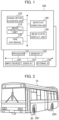
- FIG. 1 is a functional block diagram of the tire wear prediction system 100.
- a tire wear prediction system 100 predicts the wear state of a tire mounted at a predetermined wheel position of a vehicle. Specifically, the tire wear prediction system 100 predicts the wear amount from the tire in a new state based on a known prediction method, and accurately predicts the wear amount of the tire even when tire rotation and replacement with another tire are performed.
- the prediction method is not limited to these methods, and may be any method as long as the amount of wear of the tire mounted at a predetermined wheel position can be predicted based on the traveling state (Traveling speed, acceleration/deceleration/left-right G, steering angle, load, tire pressure, etc.) of the vehicle.
- FIG. 2 is a schematic perspective view of a bus 10 equipped with a tire 30 to be an object of the tire wear prediction system 100.
- the bus 10 is a vehicle having two axles, a front wheel axle 20 F and a rear wheel axle 20 R.
- the front wheel axle 20 F and the rear wheel axle 20 R are mounted with a plurality of tires 30.
- the front wheel axle 20 F is a steering axle, and the tire 30 mounted on the front wheel axle 20 F is called a steering wheel (steered wheel).
- the rear wheel axle 20 R is a drive axle, and the tire 30 mounted on the rear wheel axle 20 R is called a drive wheel.
- the bus 10 is a kind of vehicle to be managed by the tire wear prediction system 100, and is a large vehicle (heavy load vehicle) capable of transporting a large number of passengers.
- the tire 30 mounted on the bus 10 is a tire for heavy load.
- the bus 10 includes various sensors for detecting the value of a parameter (See below.) indicating the traveling state of the bus 10.
- the bus 10 includes sensors for detecting the traveling speed, acceleration, deceleration, left and right G, steering angle, load, and tire pressure. These sensors may be shared with the installation of the bus 10 (including tire pressure monitoring systems (TPMS)), or may be installed for predicting the wear state of the tire 30.
- TPMS tire pressure monitoring systems
- FIG. 3 is an explanatory diagram of the axle configuration of the bus 10. As shown in FIG. 3 , at the wheel position # 1 (POS.1, position of front left wheel ((1) in the figure)), the tire 30 identified as Tire 1 is mounted. At the wheel position # 2 (POS.2, position of front right wheel ((2) in the figure)), a tire 30 identified as Tire 2 is mounted.
- each of POS. 3 to 6 (left outer rear wheel, left inner rear wheel, right inner rear wheel, right outer rear wheel, ((3) to (6) in the figure) is mounted with a tire 30 identified as Tire 3 - 6.
- the tire wear prediction system 100 includes a wear prediction unit 110, a change history acquisition unit 120, a tire database 130, a wear state correction unit 140, and a wear state display unit 150.
- the tire wear prediction system 100 includes, as hardware elements, a processor 101, a memory 103, an input device 105, a display 107, and an external IF 109.
- the wear prediction unit 110 predicts the wear state of the tire 30. Specifically, the wear prediction unit 110 predicts the wear state of the new tire 30 using the known prediction method described above.
- the wear prediction unit 110 predicts, based on the traveling state of the bus 10 (Vehicle), the wear state of the tire 30 mounted at a predetermined wheel position (Pos. 1-6 in FIG. 3 ) of the bus 10.
- the traveling state of the bus 10 is a state of the bus 10 determined mainly based on the following parameters. Specifically, Traveling speed, traveling distance, acceleration/deceleration/left-right G, driving force, braking force, lateral force, steering angle, yaw rate, roll rate, pitch rate, load (carrying capacity), and the like can be cited.
- a wear prediction unit 110 predicts the wear state of the tire 30 by using part or all of these parameters.
- a wear prediction unit 110 acquires a parameter indicating the traveling state of the bus 10 via a communication network. Specifically, the wear prediction unit 110 acquires measurement data from various sensors mounted on the bus 10 via a wireless communication network or a combination of a wireless communication network and a wired communication network.
- the wear prediction unit 110 uses the acquired measurement data to predict the wear state of the tire 30 mounted at each wheel position, but the prediction may not necessarily be performed in real time. That is, the prediction of the wear state of the tire 30 may be executed as a batch process every predetermined period (For example, on a daily or weekly basis).
- the wear state of the tire 30 is, in short, the wear amount of the tire 30. Based on the predicted wear state of the tire 30, the depth of the groove formed in the tread of the tire 30 (residual groove depth) may be indicated.
- the wear prediction unit 110 predicts the wear state of the tire 30 based on a reference of the wear state corrected by the wear state correction unit 140. Specifically, the wear prediction unit 110 acquires the presence/absence of tire rotation or the presence/absence of replacement with another tire from the wear state correction unit 140.
- the tire rotation means to change the wheel position of the tire 30 (rotation) mounted on the bus 10 to the other wheel position among the plurality of tires 30 mounted on the bus 10.
- Replacement with another tire means replacement with another tire that was not attached to the bus 10 (New or used). This includes changes to different tire brands (Product name, etc.) or types (Summer tires and studiess tires (winter tire), etc.).
- the wear prediction unit 110 when acquiring the information from the wear state correction unit 140, that is, when acquiring the reference of the corrected wear state, refers to the tire database 130 as necessary, and changes a prediction method of the wear state of the tire 30 and a value of a parameter used for the prediction of the wear state.
- the wear prediction unit 110 can switch to a prediction method for delaying the progress of the wear state after the wear of the tire 30 progresses to a certain degree (referred to as "tread rigidity modification").
- a change history acquisition unit 120 acquires a change history of a tire 30 mounted on the bus 10. Specifically, the change history acquisition unit 120 acquires a change history including the rotation of the wheel position (tire rotation) on which the tire 30 is mounted or the content of replacement with another tire.
- the change history may be automatically acquired using the ID of the TPMS measurement unit provided on the tire 30 (Specifically, tire 30 assembled to a rim wheel), or may be acquired by manual or semi-manual input (Use of a hand-held module for reading the ID of the tire 30, etc.) by a user or the like.
- the tire database 130 comprises items related to tires 30 that may be mounted on the bus 10.
- FIG. 5 shows an example of the tire database 130.
- the tire database 130 includes items of "Tire ID”, “Tire type”, “Size”, “Brand”, “residual groove amount”, and "wear characteristic”.
- the "Tire ID” is unique identification information given to the tire 30.
- "Tire type” is a type corresponding to the performance of the tire 30 (In FIG. 5 , summer, all seasons and studless). The type may depend on the value of rolling resistance, the rigidity of the tread rubber, etc.
- Size is the size of the tire 30 (tread width, wheel diameter), and "Brand” corresponds to a product name of the tire 30 (brand name), etc.
- “residual groove amount” is the remaining groove depth of a groove formed in the tread of the tire 30. In the case of a new one, N.A. (Not Applicable) is set.
- Wear characteristic is the characteristic (Tread rubber material and rigidity, etc.) of the tire used to predict the wear state of the tire. The wear characteristics are different depending on the axle on which the tire 30 is mounted (Front axle 20 F (steering axle) or rear axle 20 R (drive axle)).
- the tread rigidity correction described above is also performed using the "wear characteristic".
- “A'" and “C'” in FIG. 5 show wear characteristics after the wear of the tire progresses to a certain degree.
- a wear state correction unit 140 corrects the standard of the wear state of the tire 120 predicted by the wear prediction unit 110 based on the change history of the tire 30 acquired by the change history acquisition unit 30.
- the wear state correction unit 140 corrects the reference of the wear state based on the wheel position after the rotation. For example, when the tire 30 is moved from the front wheel axle 20 F (POS.1) to the rear wheel axle 20 R (POS.3), the wear characteristics for the steering wheel are changed to the wear characteristics for the driving wheel. Thus, the reference of the wear state of the tire 30 is corrected.
- the wear state correction unit 140 may automatically change the wear characteristics by using a parameter indicating the traveling state of the bus 10.
- the wear state correction unit 140 corrects the standard of the wear state on the basis of at least one of the brand, the type and whether or not the tire is new.
- the wear state correction unit 140 changes the wear characteristics used for predicting the wear state of the tire 30 from “A” to "A'".
- the "A'" indicates the wear characteristics (Tread rigidity has been modified) after the wear of the tire progresses to a certain degree.
- the reference of the wear state of the tire 30 is corrected.
- An abrasion state display unit 150 displays the abrasion state of the tire 110 predicted by the abrasion prediction unit 30. Specifically, the wear state display unit 150 displays the wear state of the tire 30 for each wheel position.
- FIG. 6 shows a display example of the wear state of the tire 30 by the wear state display unit 150.
- the horizontal axes (1) to (6) of the graph shown in FIG. 6 correspond to the wheel positions shown in FIG. 3 .
- the vertical axis of the graph indicates the wear amount (Units: mm) of the tire 30 mounted at each wheel position.
- the "limit of use" of the wear amount corresponds to the state in which the tread of the tire 30 is worn to the limit in which it can be legally used.
- the tread-ware indicator is exposed to the tread surface.
- “ideal” is an amount of wear when the vehicle travels the distance at the speed in an ideal state where no excessive wear occurs.
- the ideal state is an optimum state in which the operation of the bus 10 does not impose an unnecessary burden on the tire.
- the shape of the road on which the bus 10 has actually traveled may be taken into consideration.
- “driving wheel application” is the amount of wear caused by the driving wheels added to the amount of wear of “ideal”.
- steering wheel application is the amount of wear caused by the steering wheel applied to the amount of wear of the "ideal”.
- driving wheel application means the wear amount increased by the excessive accelerator operation by the driver
- steering wheel application means the wear amount increased by the sudden steering operation by the driver
- load application is the amount of wear attributable to the load applied to the amount of wear of the “ideal”. Specifically, the amount of wear caused by exceeding the standard loading capacity of the bus 10 (Number of passengers, etc.).
- the wear state display unit 150 can display the wear state of the tire 30 for each wear cause.
- FIG. 4 shows a prediction operation flow of the wear state of the tire 30 by the tire wear prediction system 100.
- the tire 30 mounted on the bus 10 is rotated or replaced with another tire during use.
- the tire wear prediction system 100 predicts the wear amount of the tire 30 at each wheel position of the bus 10 (S 10). Specifically, as described above, the tire wear prediction system 100 predicts the wear state of the tire 30 using a parameter indicating the traveling state of the bus 10.
- the tire wear prediction system 100 checks the existence of the change history of the tire 30 (S 20). Specifically, the tire wear prediction system 100 checks the presence or absence of tire rotation and replacement with another tire.
- the tire wear prediction system 100 determines whether or not the change history is a tire rotation (S 30).
- the tire wear prediction system 100 resets the wheel position after rotation and the wear amount of the tire 30 up to the rotation (S 40).
- the tire wear prediction system 100 changes the wear characteristics (Steering or driving axle-related, see description of FIG. 5 ) of the tire 30 as necessary based on the wheel position after rotation.
- the tire wear prediction system 100 determines whether or not the tire is replaced with a new tire (S 50).
- the tire wear prediction system 100 resets the wear amount of the tire 30 at the wheel position (S 60).
- the tire wear prediction system 100 acquires the wear amount of the replaced tire (S 70).
- the replaced tire is both a tire 30 mounted on the bus 10 before replacement and a used tire newly mounted on the bus 10.
- the wear amount of the removed tire 30 can be displayed and the wear state of the used tire can be accurately predicted.
- the tire wear prediction system 100 determines whether the tire after replacement is the same brand and the same size as the tire 30 before replacement (S 80).
- the tire wear prediction system 100 changes the wear characteristics (See the description associated with FIG. 5 ) of the tire 30 after replacement (S 90). Specifically, the tire wear prediction system 100 changes the wear characteristics corresponding to the brand and size of the replaced tire 30.
- FIG. 7 conceptually shows the prediction of the wear state of the tire 30 by the tire wear prediction system 100.
- the tire wear prediction system 100 starts predicting the wear state of the tire 30.
- a new tire 30 is mounted on the bus 10.
- the tire wear prediction system 100 predicts the wear state of the tire 10 based on the traveling state (Traveling speed, acceleration/deceleration/left-right G, steering angle, load, tire pressure, etc.) of the bus 30. As a result, it is predicted that the amount of residual (remaining) groove amount (residual groove depth) of the tire 30 decreases along the straight line ⁇ 1.
- the tire wear prediction system 100 changes the wear characteristics used for predicting the wear state of the tire 30 based on the wheel position, tire type, size, brand (including distinction between new and used), and residual groove amount (Used) on which the tire 30 is mounted.
- the tire wear prediction system 100 can display the wear state of the tire 30 as shown in FIG. 6 at any timing of the above-described steps 10 to 90.
- the tire wear prediction system 100 corrects the reference (Tire rotation or replacement with another tire) of the predicted wear state of the tire 30 based on the acquired change history (wear characteristic) of the tire 30.
- the tire wear prediction system 100 predicts the wear state of the tire 30 based on the reference of the corrected wear state.
- the wear state of the tire 30 can be accurately predicted using a known prediction method.
- the tire wear prediction system 100 can accurately predict the wear state of the tire 30 even in such a case because it corresponds to both tire rotation and replacement with another tire.
- the tire wear prediction system 100 can display the wear state of the tire 30 for each wear cause (see FIG. 6 ). Therefore, the driver of the bus 10 and the operating body of the bus 10 (Bus companies, etc.) can promote the operation of the bus 10 and the improvement of the operating method of the bus 10. Thus, the wear life of the tire 30 can be extended.
- the tire for heavy load mounted on the bus 10 has been described as an example, but it may be a large-sized vehicle other than the bus such as a truck or a vehicle (Especially for business use).
- the tire wear prediction system 100 corresponds to the tire rotation and the replacement with another tire, but may correspond to only one of the tire rotation and the tire replacement depending on the type of the target vehicle.
- the tire wear prediction system 100 displays the wear state of the tire 30 according to the cause of wear, but such display is not essential. Further, it is possible to indicate only a part of a plurality of causes of wear.
- a tire wear prediction system comprising:
- the tire wear prediction system according to clause 1 or 2, wherein the wear state correction unit corrects the reference of the wear state based on at least one of a brand, a type, and a new tire or not when the change history is a change to another tire.
- the tire wear prediction system comprises a wear state display unit for displaying the wear state predicted by the wear prediction unit; wherein the wear state display unit displays the wear state for each wear cause.
- a tire wear prediction program causing a computer to execute:
- a tire wear prediction method comprising the steps of:
- a data structure used in a tire wear prediction system for predicting a wear state of a tire mounted at a predetermined wheel position of a vehicle based on a traveling state of the vehicle including:
Landscapes
- Engineering & Computer Science (AREA)
- Mechanical Engineering (AREA)
- Physics & Mathematics (AREA)
- General Physics & Mathematics (AREA)
- Tires In General (AREA)
- Vehicle Cleaning, Maintenance, Repair, Refitting, And Outriggers (AREA)
- Management, Administration, Business Operations System, And Electronic Commerce (AREA)
Abstract
Description
- The present invention relates to a tire wear prediction system and a tire wear prediction program for predicting the wear state of a tire mounted on a vehicle. The present application is a divisional application of
EP19798846.2 - Conventionally, a method for predicting the wear state of a tire mounted on a vehicle such as an automobile has been known.
- For example, a method has been established for predicting the wear state (wear life) of a tire on the basis of wear energy at free rolling, at the time applying a toe angle, at the time applying a lateral force, at the time applying a driving force, and at the time applying a braking force, and the wear amount per predetermined traveling distance (See
Patent Literature 1.). - [PTL 1]
Japanese Patent No. 3277156 - According to
Patent Literature 1, it is possible to predict the wear state of a tire mounted on a vehicle, that is, the amount of wear of the tire with a certain degree of accuracy. However, the following problems occur in the actual operating environment of the vehicle. - Specifically, in order to prevent uneven wear of a tire mounted on a vehicle and to wear the tire uniformly to some extent, the position of a wheel mounted is generally rotated (tire rotation) during the use.
- Since the method for predicting the wear state of the tire predicts the wear state from the new tire mounted at the predetermined wheel position, when the tire rotation is performed as this manner, it becomes difficult to accurately predict the wear amount of the tire.
- Furthermore, particularly in the case of a heavy load tire mounted on a truck, a bus or the like, the tire is often replaced with another tire in stock, specifically, a new or used tire, or a tire of a different brand or type (Studless tires, etc.) at the time of tire rotation, and it becomes more difficult to predict the wear amount of the heavy load tire.
- Accordingly, an object of the present invention is to provide a tire wear prediction system, a tire wear prediction program, a tire wear prediction method and a data structure capable of accurately predicting the wear state of a tire even when the tire mounted on a vehicle is rotated or replaced with another tire.
- One aspect of the present invention is a tire wear prediction system (Tire wear prediction system 100) including a wear prediction unit (Wear prediction unit 110) for predicting a wear state of a tire mounted at a predetermined wheel position of a vehicle (Bus 10) based on a traveling state of the vehicle, a change history acquisition unit (Change history acquisition unit 120) for acquiring a change history including rotation of the wheel position on which the tire is mounted or a content of replacement with another tire, and a wear state correction unit (Wear state correction unit 140) for correcting a reference of the wear state of the tire predicted by the wear prediction unit based on the change history. The wear prediction unit predicts the wear state of the tire based on the reference of the wear state corrected by the wear state correction unit.
- One aspect of the present invention is a tire wear prediction program causing a computer to execute a wear prediction process for predicting a wear state of a tire mounted at a predetermined wheel position of a vehicle based on the traveling state of the vehicle, a change history acquiring process for acquiring a change history including rotation of the wheel position on which the tire is mounted or a content of replacement with another tire, and a wear state correction processing for correcting a reference of the wear state of the tire predicted by the wear prediction processing based on the change history. The wear prediction processing predicts the wear state of the tire based on the reference of the previous wear state corrected by the wear state correction processing.
- One aspect of the present invention is a tire wear prediction method comprising the steps of a wear prediction step of predicting a wear state of a tire mounted on a predetermined wheel position of a vehicle based on a traveling state of the vehicle, a change history acquiring step of acquiring a change history including the rotation of the wheel position on which the tire is mounted or a content of replacement with another tire, a wear state correction step of correcting a reference of the wear state of the tire predicted by the wear prediction step based on the change history. In the wear predicting step, the tire wear predicting method predicts the wear state of the tire based on the reference of the wear state corrected by the wear state correcting step.
- One aspect of the present invention is a data structure used in a tire wear prediction system for predicting a wear state of a tire mounted at a predetermined wheel position of a vehicle based on a traveling state of the vehicle, including a tire ID which is unique identification information imparted to the tire, a type of the tire, a size of the tire, a brand of the tire, a residual groove amount indicating a residual groove depth of a groove formed in a tread of the tire, and a ware characteristic indicating a characteristic of a tire used for predicting the ware state of the tire. The data structure is used in the tire wear prediction system for a process of correcting a reference of the wear state of the tire predicted by the wear prediction processing based on the change history including the rotation of the wheel position on which the tire is mounted or the content of replacement with another tire.
-
- [
FIG. 1] FIG. 1 is a functional block diagram of a tirewear prediction system 100. - [
FIG. 2] FIG. 2 is a schematic perspective view of abus 10 mounted with atire 30 that is an object of the tirewear prediction system 100. - [
FIG. 3] FIG. 3 is an illustration of the axle configuration ofbus 10. - [
FIG. 4]FIG. 4 is a diagram illustrating a predictive operational flow of tire wear state by tirewear prediction system 100 for thetire 30. - [
FIG. 5]FIG. 5 shows an example of atire database 130. - [
FIG. 6] FIG. 6 is a view showing an example of the display of the wear state of thetire 30 by a wearstate display unit 150. - [
FIG. 7] FIG. 7 is a diagram conceptually illustrating the prediction of wear state of thetire 30 by tirewear prediction system 100. - Hereinafter, an embodiment will be described based on the drawings. It should be noted that the same or similar reference numerals are given to the same functions and structures, and the description thereof will be omitted as appropriate.
-
FIG. 1 is a functional block diagram of the tirewear prediction system 100. A tirewear prediction system 100 predicts the wear state of a tire mounted at a predetermined wheel position of a vehicle. Specifically, the tirewear prediction system 100 predicts the wear amount from the tire in a new state based on a known prediction method, and accurately predicts the wear amount of the tire even when tire rotation and replacement with another tire are performed. - As known prediction methods, in addition to the aforementioned
Japanese Patent No. 3277156 Japanese Patent No. 3320653 Japanese Patent No. 3277155 -
FIG. 2 is a schematic perspective view of abus 10 equipped with atire 30 to be an object of the tirewear prediction system 100. As shown inFIG. 2 , thebus 10 is a vehicle having two axles, afront wheel axle 20 F and arear wheel axle 20 R. Thefront wheel axle 20 F and therear wheel axle 20 R are mounted with a plurality oftires 30. - The
front wheel axle 20 F is a steering axle, and thetire 30 mounted on thefront wheel axle 20 F is called a steering wheel (steered wheel). Therear wheel axle 20 R is a drive axle, and thetire 30 mounted on therear wheel axle 20 R is called a drive wheel. - The
bus 10 is a kind of vehicle to be managed by the tirewear prediction system 100, and is a large vehicle (heavy load vehicle) capable of transporting a large number of passengers. Thetire 30 mounted on thebus 10 is a tire for heavy load. - The
bus 10 includes various sensors for detecting the value of a parameter (See below.) indicating the traveling state of thebus 10. Specifically, thebus 10 includes sensors for detecting the traveling speed, acceleration, deceleration, left and right G, steering angle, load, and tire pressure. These sensors may be shared with the installation of the bus 10 (including tire pressure monitoring systems (TPMS)), or may be installed for predicting the wear state of thetire 30. -
FIG. 3 is an explanatory diagram of the axle configuration of thebus 10. As shown inFIG. 3 , at the wheel position # 1 (POS.1, position of front left wheel ((1) in the figure)), thetire 30 identified as Tire 1 is mounted. At the wheel position # 2 (POS.2, position of front right wheel ((2) in the figure)), atire 30 identified as Tire 2 is mounted. - Similarly, each of POS. 3 to 6 (left outer rear wheel, left inner rear wheel, right inner rear wheel, right outer rear wheel, ((3) to (6) in the figure) is mounted with a
tire 30 identified as Tire 3 - 6. - As shown in
FIG. 1 , the tirewear prediction system 100 includes awear prediction unit 110, a changehistory acquisition unit 120, atire database 130, a wearstate correction unit 140, and a wearstate display unit 150. - These functional blocks are implemented by executing a computer program (Software) on hardware such as a server computer. Specifically, the tire
wear prediction system 100 includes, as hardware elements, aprocessor 101, amemory 103, aninput device 105, adisplay 107, and anexternal IF 109. - The
wear prediction unit 110 predicts the wear state of thetire 30. Specifically, thewear prediction unit 110 predicts the wear state of thenew tire 30 using the known prediction method described above. - More specifically, the
wear prediction unit 110 predicts, based on the traveling state of the bus 10 (Vehicle), the wear state of thetire 30 mounted at a predetermined wheel position (Pos. 1-6 inFIG. 3 ) of thebus 10. - The traveling state of the
bus 10 is a state of thebus 10 determined mainly based on the following parameters. Specifically, Traveling speed, traveling distance, acceleration/deceleration/left-right G, driving force, braking force, lateral force, steering angle, yaw rate, roll rate, pitch rate, load (carrying capacity), and the like can be cited. Awear prediction unit 110 predicts the wear state of thetire 30 by using part or all of these parameters. - A
wear prediction unit 110 acquires a parameter indicating the traveling state of thebus 10 via a communication network. Specifically, thewear prediction unit 110 acquires measurement data from various sensors mounted on thebus 10 via a wireless communication network or a combination of a wireless communication network and a wired communication network. - The
wear prediction unit 110 uses the acquired measurement data to predict the wear state of thetire 30 mounted at each wheel position, but the prediction may not necessarily be performed in real time. That is, the prediction of the wear state of thetire 30 may be executed as a batch process every predetermined period (For example, on a daily or weekly basis). - The wear state of the
tire 30 is, in short, the wear amount of thetire 30. Based on the predicted wear state of thetire 30, the depth of the groove formed in the tread of the tire 30 (residual groove depth) may be indicated. - The
wear prediction unit 110 predicts the wear state of thetire 30 based on a reference of the wear state corrected by the wearstate correction unit 140. Specifically, thewear prediction unit 110 acquires the presence/absence of tire rotation or the presence/absence of replacement with another tire from the wearstate correction unit 140. - The tire rotation means to change the wheel position of the tire 30 (rotation) mounted on the
bus 10 to the other wheel position among the plurality oftires 30 mounted on thebus 10. - Replacement with another tire means replacement with another tire that was not attached to the bus 10 (New or used). This includes changes to different tire brands (Product name, etc.) or types (Summer tires and studiess tires (winter tire), etc.).
- The
wear prediction unit 110, when acquiring the information from the wearstate correction unit 140, that is, when acquiring the reference of the corrected wear state, refers to thetire database 130 as necessary, and changes a prediction method of the wear state of thetire 30 and a value of a parameter used for the prediction of the wear state. - Further, when the wear of the
tire 30 progresses to a certain degree, the remaining groove depth of the tread is reduced to increase the block rigidity of the tread, and therefore, thewear prediction unit 110 can switch to a prediction method for delaying the progress of the wear state after the wear of thetire 30 progresses to a certain degree (referred to as "tread rigidity modification"). - A change
history acquisition unit 120 acquires a change history of atire 30 mounted on thebus 10. Specifically, the changehistory acquisition unit 120 acquires a change history including the rotation of the wheel position (tire rotation) on which thetire 30 is mounted or the content of replacement with another tire. - The change history may be automatically acquired using the ID of the TPMS measurement unit provided on the tire 30 (Specifically,
tire 30 assembled to a rim wheel), or may be acquired by manual or semi-manual input (Use of a hand-held module for reading the ID of thetire 30, etc.) by a user or the like. - The
tire database 130 comprises items related totires 30 that may be mounted on thebus 10. -
FIG. 5 shows an example of thetire database 130. As shown inFIG. 5 , thetire database 130 includes items of "Tire ID", "Tire type", "Size", "Brand", "residual groove amount", and "wear characteristic". - The "Tire ID" is unique identification information given to the
tire 30. "Tire type" is a type corresponding to the performance of the tire 30 (InFIG. 5 , summer, all seasons and studless). The type may depend on the value of rolling resistance, the rigidity of the tread rubber, etc. - "Size" is the size of the tire 30 (tread width, wheel diameter), and "Brand" corresponds to a product name of the tire 30 (brand name), etc. "residual groove amount" is the remaining groove depth of a groove formed in the tread of the
tire 30. In the case of a new one, N.A. (Not Applicable) is set.
"wear characteristic" is the characteristic (Tread rubber material and rigidity, etc.) of the tire used to predict the wear state of the tire. The wear characteristics are different depending on the axle on which thetire 30 is mounted (Front axle 20 F (steering axle) orrear axle 20 R (drive axle)). - The tread rigidity correction described above is also performed using the "wear characteristic". For example, "A'" and "C'" in
FIG. 5 show wear characteristics after the wear of the tire progresses to a certain degree. - A wear
state correction unit 140 corrects the standard of the wear state of thetire 120 predicted by thewear prediction unit 110 based on the change history of thetire 30 acquired by the changehistory acquisition unit 30. - Specifically, when the change history of the
tire 30 is the rotation of the wheel position (Pos. 1-6 inFIG. 3 ), the wearstate correction unit 140 corrects the reference of the wear state based on the wheel position after the rotation. For example, when thetire 30 is moved from thefront wheel axle 20 F (POS.1) to therear wheel axle 20 R (POS.3), the wear characteristics for the steering wheel are changed to the wear characteristics for the driving wheel. Thus, the reference of the wear state of thetire 30 is corrected. In the case of tire rotation, the wearstate correction unit 140 may automatically change the wear characteristics by using a parameter indicating the traveling state of thebus 10. - Further, when the change history of the
tire 30 is replacement with another tire, the wearstate correction unit 140 corrects the standard of the wear state on the basis of at least one of the brand, the type and whether or not the tire is new. - For example, when the
tire 30 mounted on the POS.1 is replaced from the summer tire of "ABC" (See tire ID = 1 inFIG. 5 ) to the summer tire of "ABC" (see tire ID = 31), the wearstate correction unit 140 changes the wear characteristics used for predicting the wear state of thetire 30 from "A" to "A'". As described above, the "A'" indicates the wear characteristics (Tread rigidity has been modified) after the wear of the tire progresses to a certain degree. Thus, the reference of the wear state of thetire 30 is corrected. - An abrasion
state display unit 150 displays the abrasion state of thetire 110 predicted by theabrasion prediction unit 30. Specifically, the wearstate display unit 150 displays the wear state of thetire 30 for each wheel position. -
FIG. 6 shows a display example of the wear state of thetire 30 by the wearstate display unit 150. The horizontal axes (1) to (6) of the graph shown inFIG. 6 correspond to the wheel positions shown inFIG. 3 . The vertical axis of the graph indicates the wear amount (Units: mm) of thetire 30 mounted at each wheel position. The "limit of use" of the wear amount corresponds to the state in which the tread of thetire 30 is worn to the limit in which it can be legally used. Typically, the tread-ware indicator is exposed to the tread surface. - In
FIG. 6 , "ideal" is an amount of wear when the vehicle travels the distance at the speed in an ideal state where no excessive wear occurs. In other words, the ideal state is an optimum state in which the operation of thebus 10 does not impose an unnecessary burden on the tire. In predicting the wear amount corresponding to the "ideal", the shape of the road on which thebus 10 has actually traveled (Road type, road curvature, etc.) may be taken into consideration.
"driving wheel application" is the amount of wear caused by the driving wheels added to the amount of wear of "ideal". "steering wheel application" is the amount of wear caused by the steering wheel applied to the amount of wear of the "ideal". That is, "driving wheel application" means the wear amount increased by the excessive accelerator operation by the driver, and "steering wheel application" means the wear amount increased by the sudden steering operation by the driver.
"load application" is the amount of wear attributable to the load applied to the amount of wear of the "ideal". Specifically, the amount of wear caused by exceeding the standard loading capacity of the bus 10 (Number of passengers, etc.). - Thus, the wear
state display unit 150 can display the wear state of thetire 30 for each wear cause. - Next, the operation of the tire
wear prediction system 100 will be described. Specifically, the prediction operation of the wear state of thetire 30 by the tirewear prediction system 100 will be described. -
FIG. 4 shows a prediction operation flow of the wear state of thetire 30 by the tirewear prediction system 100. As described above, in the present embodiment, thetire 30 mounted on thebus 10 is rotated or replaced with another tire during use. - As shown in
FIG. 4 , the tirewear prediction system 100 predicts the wear amount of thetire 30 at each wheel position of the bus 10 (S 10). Specifically, as described above, the tirewear prediction system 100 predicts the wear state of thetire 30 using a parameter indicating the traveling state of thebus 10. - Next, the tire
wear prediction system 100 checks the existence of the change history of the tire 30 (S 20). Specifically, the tirewear prediction system 100 checks the presence or absence of tire rotation and replacement with another tire. - When there is a change history of the
tire 30, the tirewear prediction system 100 determines whether or not the change history is a tire rotation (S 30). - In the case of tire rotation, the tire
wear prediction system 100 resets the wheel position after rotation and the wear amount of thetire 30 up to the rotation (S 40). The tirewear prediction system 100 changes the wear characteristics (Steering or driving axle-related, see description ofFIG. 5 ) of thetire 30 as necessary based on the wheel position after rotation. - When the tire is not rotated, that is, when the tire is replaced with another tire, the tire
wear prediction system 100 determines whether or not the tire is replaced with a new tire (S 50). - In the case of replacement with a new tire, the tire
wear prediction system 100 resets the wear amount of thetire 30 at the wheel position (S 60). - On the other hand, in the case of replacement with a used tire, that is, replacement with a tire worn over a certain degree, the tire
wear prediction system 100 acquires the wear amount of the replaced tire (S 70). The replaced tire is both atire 30 mounted on thebus 10 before replacement and a used tire newly mounted on thebus 10. Thus, the wear amount of the removedtire 30 can be displayed and the wear state of the used tire can be accurately predicted. - The tire
wear prediction system 100 determines whether the tire after replacement is the same brand and the same size as thetire 30 before replacement (S 80). - When the tire after replacement is not the same brand and the same size as the
tire 30 before replacement, that is, when any of the type, brand or size is different, the tirewear prediction system 100 changes the wear characteristics (See the description associated withFIG. 5 ) of thetire 30 after replacement (S 90). Specifically, the tirewear prediction system 100 changes the wear characteristics corresponding to the brand and size of the replacedtire 30. -
FIG. 7 conceptually shows the prediction of the wear state of thetire 30 by the tirewear prediction system 100. As shown inFIG. 7 , the tirewear prediction system 100 starts predicting the wear state of thetire 30. Here, anew tire 30 is mounted on thebus 10. - The tire
wear prediction system 100 predicts the wear state of thetire 10 based on the traveling state (Traveling speed, acceleration/deceleration/left-right G, steering angle, load, tire pressure, etc.) of thebus 30. As a result, it is predicted that the amount of residual (remaining) groove amount (residual groove depth) of thetire 30 decreases along the straight line α1. - Thereafter, the tire rotation of the
tire 30 is performed. As described above, the tirewear prediction system 100 changes the wear characteristics used for predicting the wear state of thetire 30 based on the wheel position, tire type, size, brand (including distinction between new and used), and residual groove amount (Used) on which thetire 30 is mounted. - As a result, it is predicted that the remaining groove amount decreases along the straight line α2 after the tire rotation.
- In addition, the tire
wear prediction system 100 can display the wear state of thetire 30 as shown inFIG. 6 at any timing of the above-describedsteps 10 to 90. - According to the embodiment described above, the following effects can be obtained. Specifically, the tire
wear prediction system 100 corrects the reference (Tire rotation or replacement with another tire) of the predicted wear state of thetire 30 based on the acquired change history (wear characteristic) of thetire 30. The tirewear prediction system 100 predicts the wear state of thetire 30 based on the reference of the corrected wear state. - Therefore, even when the
tire 30 mounted on thebus 10 is rotated or replaced with another tire, the wear state of thetire 30 can be accurately predicted using a known prediction method. - In particular, commercial vehicles such as trucks and buses have high frequency of tire rotation and replacement with other tires, and are often replaced with new or used tires or tires of different brand or type (Studless tires, etc.). The tire
wear prediction system 100 can accurately predict the wear state of thetire 30 even in such a case because it corresponds to both tire rotation and replacement with another tire. - In the present embodiment, the tire
wear prediction system 100 can display the wear state of thetire 30 for each wear cause (seeFIG. 6 ). Therefore, the driver of thebus 10 and the operating body of the bus 10 (Bus companies, etc.) can promote the operation of thebus 10 and the improvement of the operating method of thebus 10. Thus, the wear life of thetire 30 can be extended. - While the contents of the present invention have been described in accordance with the above embodiments, it will be apparent to those skilled in the art that the present invention is not limited to these descriptions and that various modifications and improvements are possible.
- For example, in the embodiment described above, the tire for heavy load mounted on the
bus 10 has been described as an example, but it may be a large-sized vehicle other than the bus such as a truck or a vehicle (Especially for business use). - In the above-described embodiment, the tire
wear prediction system 100 corresponds to the tire rotation and the replacement with another tire, but may correspond to only one of the tire rotation and the tire replacement depending on the type of the target vehicle. - In the above-described embodiment, the tire
wear prediction system 100 displays the wear state of thetire 30 according to the cause of wear, but such display is not essential. Further, it is possible to indicate only a part of a plurality of causes of wear. - Although embodiments of the invention have been described as described above, the discussion and drawings which form part of this disclosure should not be construed as limiting the invention. Various alternative embodiments, embodiments and operational techniques will be apparent to those skilled in the art from this disclosure.
-
- 10 Bus
- 20 F Front wheel axle
- 20 R rear wheel axle
- 30 Tire
- 100 Tire wear prediction system
- 101 Processor
- 103 Memory
- 105 Input device
- 107 Display
- 109 External IF
- 110 Wear prediction unit
- 120 Change history acquisition unit
- 130 Tire database
- 140 Wear state correction unit
- 150 Wear state display unit
- The present application discloses the inventions defined by the following clauses:
- A tire wear prediction system, comprising:
- a wear prediction unit for predicting a wear state of a tire mounted at a predetermined wheel position of a vehicle based on a traveling state of the vehicle;
- a change history acquisition unit for acquiring a change history including rotation of the wheel position on which the tire is mounted or a content of replacement with another tire; and
- a wear state correction unit for correcting a reference of the wear state of the tire predicted by the wear prediction unit based on the change history, wherein
- the wear prediction unit predicts the wear state of the tire based on the reference of the wear state corrected by the wear state correction unit.
- The tire wear prediction system according to
clause 1, wherein the wear state correction unit corrects the reference of the wear state based on the wheel position after the rotation when the change history is the rotation of the wheel position. - The tire wear prediction system according to
clause - The tire wear prediction system according to any one of
clauses 1 to 3, wherein the tire wear prediction system comprises a wear state display unit for displaying the wear state predicted by the wear prediction unit; wherein
the wear state display unit displays the wear state for each wear cause. - A tire wear prediction program causing a computer to execute:
- a wear prediction process for predicting a wear state of a tire mounted at a predetermined wheel position of a vehicle based on the traveling state of the vehicle;
- a change history acquiring process for acquiring a change history including rotation of the wheel position on which the tire is mounted or a content of replacement with another tire; and
- a wear state correction processing for correcting a reference of the wear state of the tire predicted by the wear prediction processing based on the change history; wherein
- the wear prediction processing predicts the wear state of the tire based on the reference of the previous wear state corrected by the wear state correction processing.
- A tire wear prediction method comprising the steps of:
- a wear prediction step of predicting a wear state of a tire mounted on a predetermined wheel position of a vehicle based on a traveling state of the vehicle;
- a change history acquiring step of acquiring a change history including the rotation of the wheel position on which the tire is mounted or a content of replacement with another tire;
- a wear state correction step of correcting a reference of the wear state of the tire predicted by the wear prediction step based on the change history; wherein
- in the wear predicting step, the tire wear predicting method predicts the wear state of the tire based on the reference of the wear state corrected by the wear state correcting step.
- A data structure used in a tire wear prediction system for predicting a wear state of a tire mounted at a predetermined wheel position of a vehicle based on a traveling state of the vehicle; including:
- a tire ID which is unique identification information imparted to the tire;
- a type of the tire;
- a size of the tire;
- a brand of the tire;
- a residual groove amount indicating a residual groove depth of a groove formed in a tread of the tire; and
- a ware characteristic indicating a characteristic of a tire used for predicting the ware state of the tire; wherein
- the data structure is used in the tire wear prediction system for a process of correcting a reference of the wear state of the tire predicted by the wear prediction processing based on the change history including the rotation of the wheel position on which the tire is mounted or the content of replacement with another tire.
Claims (5)
- A tire wear prediction system (100), comprising:a wear prediction unit (110) for predicting a wear state of a tire (30) mounted at a predetermined wheel position of a vehicle (10) based on a traveling state of the vehicle;a change history acquisition unit (120) for acquiring a change history including rotation of the wheel position on which the tire (30) is mounted or a content of replacement with another tire; anda wear state correction unit (140) for correcting a reference of the wear state of the tire (30) predicted by the wear prediction unit (110) based on the change history, whereinthe wear prediction unit (110):predicts the wear state of the tire (30) based on the reference of the wear state corrected by the wear state correction unit (140) andswitches to a prediction method for delaying a progress of the wear state after wear of the tire (30) progresses.
- The tire wear prediction system according to claim 1, wherein the wear state correction unit corrects the reference of the wear state based on the wheel position after the rotation when the change history is the rotation of the wheel position.
- The tire wear prediction system according to claim 1 or 2, wherein the wear state correction unit corrects the reference of the wear state based on at least one of a brand, a type, and a new tire or not when the change history is a change to another tire.
- A tire wear prediction program causing a computer to execute:a wear prediction process for predicting a wear state of a tire (30) mounted at a predetermined wheel position of a vehicle based on the traveling state of the vehicle;a change history acquiring process for acquiring a change history including rotation of the wheel position on which the tire (30) is mounted or a content of replacement with another tire; anda wear state correction processing for correcting a reference of the wear state of the tire (30) predicted by the wear prediction processing based on the change history; whereinthe wear prediction processing:predicts the wear state of the tire (30) based on the reference of the previous wear state corrected by the wear state correction processing, andswitches to a prediction method for delaying a progress of the wear state after wear of the tire (30) progresses.
- A tire wear prediction method comprising the steps of:a wear prediction step of predicting a wear state of a tire (30) mounted on a predetermined wheel position of a vehicle based on a traveling state of the vehicle;a change history acquiring step of acquiring a change history including the rotation of the wheel position on which the tire (30) is mounted or a content of replacement with another tire;a wear state correction step of correcting a reference of the wear state of the tire predicted by the wear prediction step based on the change history; whereinin the wear predicting step, the tire wear predicting method predicts the wear state of the tire (30) based on the reference of the wear state corrected by the wear state correcting step and switches to a prediction method for delaying a progress of the wear state after wear of the tire (30) progresses.
Applications Claiming Priority (3)
| Application Number | Priority Date | Filing Date | Title |
|---|---|---|---|
| JP2018091256 | 2018-05-10 | ||
| PCT/JP2019/018670 WO2019216399A1 (en) | 2018-05-10 | 2019-05-10 | Tire wear prediction system, tire wear prediction program, tire wear prediction method, and data structure |
| EP19798846.2A EP3779393B1 (en) | 2018-05-10 | 2019-05-10 | Tire wear prediction system, tire wear prediction program, tire wear prediction method, and data structure |
Related Parent Applications (2)
| Application Number | Title | Priority Date | Filing Date |
|---|---|---|---|
| EP19798846.2A Division EP3779393B1 (en) | 2018-05-10 | 2019-05-10 | Tire wear prediction system, tire wear prediction program, tire wear prediction method, and data structure |
| EP19798846.2A Division-Into EP3779393B1 (en) | 2018-05-10 | 2019-05-10 | Tire wear prediction system, tire wear prediction program, tire wear prediction method, and data structure |
Publications (3)
| Publication Number | Publication Date |
|---|---|
| EP4242014A2 true EP4242014A2 (en) | 2023-09-13 |
| EP4242014A3 EP4242014A3 (en) | 2023-10-18 |
| EP4242014B1 EP4242014B1 (en) | 2025-07-02 |
Family
ID=68468089
Family Applications (2)
| Application Number | Title | Priority Date | Filing Date |
|---|---|---|---|
| EP19798846.2A Active EP3779393B1 (en) | 2018-05-10 | 2019-05-10 | Tire wear prediction system, tire wear prediction program, tire wear prediction method, and data structure |
| EP23179071.8A Active EP4242014B1 (en) | 2018-05-10 | 2019-05-10 | Tire wear prediction system, tire wear prediction program, tire wear prediction method, and data structure |
Family Applications Before (1)
| Application Number | Title | Priority Date | Filing Date |
|---|---|---|---|
| EP19798846.2A Active EP3779393B1 (en) | 2018-05-10 | 2019-05-10 | Tire wear prediction system, tire wear prediction program, tire wear prediction method, and data structure |
Country Status (4)
| Country | Link |
|---|---|
| US (2) | US11945264B2 (en) |
| EP (2) | EP3779393B1 (en) |
| JP (2) | JP7522032B2 (en) |
| WO (1) | WO2019216399A1 (en) |
Families Citing this family (8)
| Publication number | Priority date | Publication date | Assignee | Title |
|---|---|---|---|---|
| JP7481887B2 (en) * | 2020-04-09 | 2024-05-13 | 株式会社ブリヂストン | TIRE PERFORMANCE ESTIMATION SYSTEM, TIRE PERFORMANCE ESTIMATION METHOD, AND TIRE PERFORMANCE ESTIMATION PROGRAM |
| JP2021172280A (en) * | 2020-04-28 | 2021-11-01 | Tdk株式会社 | Tire deterioration detection system, tire wear detection system, and tire wear detection method |
| EP4153435A1 (en) * | 2020-07-29 | 2023-03-29 | Sensata Technologies, Inc. | Elimination of manual reset upon tire installation in tire management systems |
| WO2022051044A1 (en) * | 2020-09-02 | 2022-03-10 | Bridgestone Americas Tire Operations, Llc | Vehicle tire localization system and method using temperature rise data |
| JP7666025B2 (en) * | 2021-03-05 | 2025-04-22 | 住友ゴム工業株式会社 | How to evaluate wandering performance |
| JP7618489B2 (en) * | 2021-04-13 | 2025-01-21 | 株式会社ブリヂストン | Tire management device and tire management method |
| US12319097B2 (en) * | 2022-08-31 | 2025-06-03 | Ford Global Technologies, Llc | System and method for monitoring tire tread and recommending a tire rotation service |
| JP2024040784A (en) * | 2022-09-13 | 2024-03-26 | Toyo Tire株式会社 | Tire maintenance support device and tire maintenance support program |
Citations (3)
| Publication number | Priority date | Publication date | Assignee | Title |
|---|---|---|---|---|
| JP3277155B2 (en) | 1998-05-08 | 2002-04-22 | 株式会社ブリヂストン | Tire wear life prediction method |
| JP3277156B2 (en) | 1998-05-08 | 2002-04-22 | 株式会社ブリヂストン | Tire wear life prediction method |
| JP3320653B2 (en) | 1998-05-08 | 2002-09-03 | 株式会社ブリヂストン | Tire wear life prediction method |
Family Cites Families (21)
| Publication number | Priority date | Publication date | Assignee | Title |
|---|---|---|---|---|
| JPH03277156A (en) | 1990-03-23 | 1991-12-09 | Fuji Electric Co Ltd | Outer rotor type spindle motor |
| JP3418121B2 (en) | 1997-07-10 | 2003-06-16 | 住友ゴム工業株式会社 | Apparatus and method for detecting tire wear state |
| JP4265334B2 (en) * | 2003-06-18 | 2009-05-20 | トヨタ自動車株式会社 | Tire wear warning device |
| JP4476030B2 (en) * | 2004-06-11 | 2010-06-09 | 日本輸送機株式会社 | Tire wear detection device and industrial vehicle equipped with the same |
| DE102005052476A1 (en) * | 2005-11-03 | 2007-05-10 | Continental Aktiengesellschaft | Method for individually estimating the actual and average wear of a vehicle tire comprises measuring the wear on the tire and emitting an acoustic and/or visual signal when the required level of maximum performance of the tire is reached |
| ITRE20070128A1 (en) * | 2007-12-19 | 2009-06-20 | Corghi Spa | "METHOD AND DEVICE FOR VEHICLE EFFICIENCY CONTROL" |
| CA2762146A1 (en) * | 2011-01-26 | 2012-07-26 | The Goodyear Tire & Rubber Company | Tire management system |
| US9530121B2 (en) * | 2011-12-19 | 2016-12-27 | Hunter Engineering Company | Vehicle service procedures |
| JP5956250B2 (en) | 2012-05-24 | 2016-07-27 | 株式会社ブリヂストン | Tire uneven wear detection method and tire uneven wear detection device |
| JP6084515B2 (en) * | 2013-05-24 | 2017-02-22 | 太平洋工業株式会社 | Wheel position determination device |
| JP2015051704A (en) | 2013-09-06 | 2015-03-19 | 株式会社デンソー | Drive support apparatus |
| US10245906B2 (en) * | 2014-11-11 | 2019-04-02 | The Goodyear Tire & Rubber Company | Tire wear compensated load estimation system and method |
| JP6401592B2 (en) * | 2014-12-02 | 2018-10-10 | 住友ゴム工業株式会社 | Evaluation method of tire tread stiffness |
| FR3030717B1 (en) | 2014-12-17 | 2017-01-13 | Michelin & Cie | METHOD FOR MEASURING THE THICKNESS OF A LAYER OF RUBBER MATERIAL |
| JP2017156295A (en) * | 2016-03-04 | 2017-09-07 | 三菱重工業株式会社 | Tire wear life estimation system |
| JP2017161477A (en) * | 2016-03-11 | 2017-09-14 | 株式会社ブリヂストン | Tire load estimation method and tire load estimation device |
| JP6702806B2 (en) | 2016-06-09 | 2020-06-03 | 株式会社ブリヂストン | Tire management device and tire management program |
| JP6332362B2 (en) * | 2016-07-22 | 2018-05-30 | 横浜ゴム株式会社 | Tire sales management system, tire sales management method, and tire sales management program |
| US10809742B2 (en) * | 2017-03-06 | 2020-10-20 | The Goodyear Tire & Rubber Company | System and method for tire sensor-based autonomous vehicle fleet management |
| JP6846239B2 (en) * | 2017-03-07 | 2021-03-24 | 株式会社ブリヂストン | Tire position change proposal program and tire position change proposal method |
| US10730352B2 (en) * | 2018-02-22 | 2020-08-04 | Ford Global Technologies, Llc | System and method for tire wear prognostics |
-
2019
- 2019-05-10 EP EP19798846.2A patent/EP3779393B1/en active Active
- 2019-05-10 JP JP2020518346A patent/JP7522032B2/en active Active
- 2019-05-10 EP EP23179071.8A patent/EP4242014B1/en active Active
- 2019-05-10 US US17/053,852 patent/US11945264B2/en active Active
- 2019-05-10 WO PCT/JP2019/018670 patent/WO2019216399A1/en not_active Ceased
-
2023
- 2023-05-24 JP JP2023085498A patent/JP7603101B2/en active Active
-
2024
- 2024-03-01 US US18/592,636 patent/US12409685B2/en active Active
Patent Citations (3)
| Publication number | Priority date | Publication date | Assignee | Title |
|---|---|---|---|---|
| JP3277155B2 (en) | 1998-05-08 | 2002-04-22 | 株式会社ブリヂストン | Tire wear life prediction method |
| JP3277156B2 (en) | 1998-05-08 | 2002-04-22 | 株式会社ブリヂストン | Tire wear life prediction method |
| JP3320653B2 (en) | 1998-05-08 | 2002-09-03 | 株式会社ブリヂストン | Tire wear life prediction method |
Also Published As
| Publication number | Publication date |
|---|---|
| JP2023105007A (en) | 2023-07-28 |
| JPWO2019216399A1 (en) | 2021-05-27 |
| JP7603101B2 (en) | 2024-12-19 |
| EP4242014B1 (en) | 2025-07-02 |
| EP4242014A3 (en) | 2023-10-18 |
| EP3779393A1 (en) | 2021-02-17 |
| EP3779393A4 (en) | 2021-11-17 |
| JP7522032B2 (en) | 2024-07-24 |
| WO2019216399A1 (en) | 2019-11-14 |
| US11945264B2 (en) | 2024-04-02 |
| EP3779393B1 (en) | 2024-03-27 |
| US20210229504A1 (en) | 2021-07-29 |
| US20240198732A1 (en) | 2024-06-20 |
| US12409685B2 (en) | 2025-09-09 |
Similar Documents
| Publication | Publication Date | Title |
|---|---|---|
| US12409685B2 (en) | Tire wear prediction system, tire wear prediction program, tire wear prediction method and data structure | |
| US11472236B2 (en) | Method, control device, and system for determining a profile depth of a profile of a tire | |
| EP3807105B1 (en) | Tread wear monitoring system and method | |
| US20210188017A1 (en) | Tread Wear Monitoring System and Method | |
| US8589025B2 (en) | Tire cornering power on-board estimation and monitoring using steering moment | |
| EP2865572A1 (en) | Road friction estimation system and method | |
| KR101745093B1 (en) | Apparatus and method for monitoring tire pressure of vehicle | |
| JP6949514B2 (en) | Tire maintenance support system, tire maintenance support program and tire maintenance support method | |
| US20130151075A1 (en) | System and method for vehicle rollover prediction | |
| EP3512722B1 (en) | Method and device for determining a wheel load acting on a wheel of a vehicle, and method and device for determining a weight of a vehicle | |
| JP6985805B2 (en) | Tire maintenance support system, tire maintenance support program and tire maintenance support method | |
| US20230196854A1 (en) | Tire replacement system | |
| JP2022100865A (en) | Tyre wear state estimation device | |
| CN109823334A (en) | Reduce automatic parking tracking error method and system | |
| CN111204331B (en) | Electronic stability control for automobile prevention | |
| US6339957B1 (en) | Apparatus for identifying tires and method thereof | |
| CN119768285A (en) | Device and method for calculating and/or monitoring the wear rate of a tire | |
| EP4725717A1 (en) | Tire wear estimation device and wear estimation method | |
| CN116373996B (en) | Double-rear drive axle steering control method, device, equipment and readable storage medium | |
| EP4140838B1 (en) | Road condition monitoring system and method | |
| WO2017095301A1 (en) | Method and system for facilitating steering of a vehicle during driving along a road | |
| JP4796470B2 (en) | Tire pressure abnormality detection device, method and program | |
| CN114954477A (en) | Real-time state monitoring method, device, vehicle and storage medium for vehicle chassis | |
| US12330454B2 (en) | System for auto-location of tires employing footprint length | |
| EP4509374B1 (en) | Surface friction determination |
Legal Events
| Date | Code | Title | Description |
|---|---|---|---|
| PUAI | Public reference made under article 153(3) epc to a published international application that has entered the european phase |
Free format text: ORIGINAL CODE: 0009012 |
|
| STAA | Information on the status of an ep patent application or granted ep patent |
Free format text: STATUS: REQUEST FOR EXAMINATION WAS MADE |
|
| 17P | Request for examination filed |
Effective date: 20230613 |
|
| AC | Divisional application: reference to earlier application |
Ref document number: 3779393 Country of ref document: EP Kind code of ref document: P |
|
| AK | Designated contracting states |
Kind code of ref document: A2 Designated state(s): AL AT BE BG CH CY CZ DE DK EE ES FI FR GB GR HR HU IE IS IT LI LT LU LV MC MK MT NL NO PL PT RO RS SE SI SK SM TR |
|
| REG | Reference to a national code |
Ref country code: DE Ref legal event code: R079 Free format text: PREVIOUS MAIN CLASS: B60C0011240000 Ipc: G01M0017020000 Ref country code: DE Ref legal event code: R079 Ref document number: 602019072185 Country of ref document: DE Free format text: PREVIOUS MAIN CLASS: B60C0011240000 Ipc: G01M0017020000 |
|
| PUAL | Search report despatched |
Free format text: ORIGINAL CODE: 0009013 |
|
| AK | Designated contracting states |
Kind code of ref document: A3 Designated state(s): AL AT BE BG CH CY CZ DE DK EE ES FI FR GB GR HR HU IE IS IT LI LT LU LV MC MK MT NL NO PL PT RO RS SE SI SK SM TR |
|
| RIC1 | Information provided on ipc code assigned before grant |
Ipc: B60C 11/24 20060101ALI20230913BHEP Ipc: B60C 23/04 20060101ALI20230913BHEP Ipc: B60C 19/00 20060101ALI20230913BHEP Ipc: G01M 17/02 20060101AFI20230913BHEP |
|
| GRAP | Despatch of communication of intention to grant a patent |
Free format text: ORIGINAL CODE: EPIDOSNIGR1 |
|
| STAA | Information on the status of an ep patent application or granted ep patent |
Free format text: STATUS: GRANT OF PATENT IS INTENDED |
|
| RIC1 | Information provided on ipc code assigned before grant |
Ipc: B60C 11/24 20060101ALI20241217BHEP Ipc: B60C 23/04 20060101ALI20241217BHEP Ipc: B60C 19/00 20060101ALI20241217BHEP Ipc: G01M 17/02 20060101AFI20241217BHEP |
|
| INTG | Intention to grant announced |
Effective date: 20250116 |
|
| GRAS | Grant fee paid |
Free format text: ORIGINAL CODE: EPIDOSNIGR3 |
|
| P01 | Opt-out of the competence of the unified patent court (upc) registered |
Free format text: CASE NUMBER: APP_16548/2025 Effective date: 20250404 |
|
| GRAA | (expected) grant |
Free format text: ORIGINAL CODE: 0009210 |
|
| STAA | Information on the status of an ep patent application or granted ep patent |
Free format text: STATUS: THE PATENT HAS BEEN GRANTED |
|
| AC | Divisional application: reference to earlier application |
Ref document number: 3779393 Country of ref document: EP Kind code of ref document: P |
|
| AK | Designated contracting states |
Kind code of ref document: B1 Designated state(s): AL AT BE BG CH CY CZ DE DK EE ES FI FR GB GR HR HU IE IS IT LI LT LU LV MC MK MT NL NO PL PT RO RS SE SI SK SM TR |
|
| REG | Reference to a national code |
Ref country code: GB Ref legal event code: FG4D |
|
| REG | Reference to a national code |
Ref country code: CH Ref legal event code: EP |
|
| REG | Reference to a national code |
Ref country code: DE Ref legal event code: R096 Ref document number: 602019072185 Country of ref document: DE |
|
| REG | Reference to a national code |
Ref country code: IE Ref legal event code: FG4D |
|
| REG | Reference to a national code |
Ref country code: NL Ref legal event code: MP Effective date: 20250702 |
|
| PG25 | Lapsed in a contracting state [announced via postgrant information from national office to epo] |
Ref country code: PT Free format text: LAPSE BECAUSE OF FAILURE TO SUBMIT A TRANSLATION OF THE DESCRIPTION OR TO PAY THE FEE WITHIN THE PRESCRIBED TIME-LIMIT Effective date: 20251103 |
|
| PG25 | Lapsed in a contracting state [announced via postgrant information from national office to epo] |
Ref country code: NL Free format text: LAPSE BECAUSE OF FAILURE TO SUBMIT A TRANSLATION OF THE DESCRIPTION OR TO PAY THE FEE WITHIN THE PRESCRIBED TIME-LIMIT Effective date: 20250702 |
|
| REG | Reference to a national code |
Ref country code: AT Ref legal event code: MK05 Ref document number: 1809704 Country of ref document: AT Kind code of ref document: T Effective date: 20250702 |
|
| PG25 | Lapsed in a contracting state [announced via postgrant information from national office to epo] |
Ref country code: IS Free format text: LAPSE BECAUSE OF FAILURE TO SUBMIT A TRANSLATION OF THE DESCRIPTION OR TO PAY THE FEE WITHIN THE PRESCRIBED TIME-LIMIT Effective date: 20251102 |
|
| PG25 | Lapsed in a contracting state [announced via postgrant information from national office to epo] |
Ref country code: NO Free format text: LAPSE BECAUSE OF FAILURE TO SUBMIT A TRANSLATION OF THE DESCRIPTION OR TO PAY THE FEE WITHIN THE PRESCRIBED TIME-LIMIT Effective date: 20251002 |
|
| REG | Reference to a national code |
Ref country code: LT Ref legal event code: MG9D |
|
| PG25 | Lapsed in a contracting state [announced via postgrant information from national office to epo] |
Ref country code: AT Free format text: LAPSE BECAUSE OF FAILURE TO SUBMIT A TRANSLATION OF THE DESCRIPTION OR TO PAY THE FEE WITHIN THE PRESCRIBED TIME-LIMIT Effective date: 20250702 |
|
| PG25 | Lapsed in a contracting state [announced via postgrant information from national office to epo] |
Ref country code: FI Free format text: LAPSE BECAUSE OF FAILURE TO SUBMIT A TRANSLATION OF THE DESCRIPTION OR TO PAY THE FEE WITHIN THE PRESCRIBED TIME-LIMIT Effective date: 20250702 |
|
| PG25 | Lapsed in a contracting state [announced via postgrant information from national office to epo] |
Ref country code: HR Free format text: LAPSE BECAUSE OF FAILURE TO SUBMIT A TRANSLATION OF THE DESCRIPTION OR TO PAY THE FEE WITHIN THE PRESCRIBED TIME-LIMIT Effective date: 20250702 |
|
| PG25 | Lapsed in a contracting state [announced via postgrant information from national office to epo] |
Ref country code: GR Free format text: LAPSE BECAUSE OF FAILURE TO SUBMIT A TRANSLATION OF THE DESCRIPTION OR TO PAY THE FEE WITHIN THE PRESCRIBED TIME-LIMIT Effective date: 20251003 |
|
| PG25 | Lapsed in a contracting state [announced via postgrant information from national office to epo] |
Ref country code: CZ Free format text: LAPSE BECAUSE OF FAILURE TO SUBMIT A TRANSLATION OF THE DESCRIPTION OR TO PAY THE FEE WITHIN THE PRESCRIBED TIME-LIMIT Effective date: 20250702 Ref country code: SE Free format text: LAPSE BECAUSE OF FAILURE TO SUBMIT A TRANSLATION OF THE DESCRIPTION OR TO PAY THE FEE WITHIN THE PRESCRIBED TIME-LIMIT Effective date: 20250702 |
|
| PG25 | Lapsed in a contracting state [announced via postgrant information from national office to epo] |
Ref country code: LV Free format text: LAPSE BECAUSE OF FAILURE TO SUBMIT A TRANSLATION OF THE DESCRIPTION OR TO PAY THE FEE WITHIN THE PRESCRIBED TIME-LIMIT Effective date: 20250702 |
|
| PG25 | Lapsed in a contracting state [announced via postgrant information from national office to epo] |
Ref country code: PL Free format text: LAPSE BECAUSE OF FAILURE TO SUBMIT A TRANSLATION OF THE DESCRIPTION OR TO PAY THE FEE WITHIN THE PRESCRIBED TIME-LIMIT Effective date: 20250702 Ref country code: BG Free format text: LAPSE BECAUSE OF FAILURE TO SUBMIT A TRANSLATION OF THE DESCRIPTION OR TO PAY THE FEE WITHIN THE PRESCRIBED TIME-LIMIT Effective date: 20250702 |
|
| PG25 | Lapsed in a contracting state [announced via postgrant information from national office to epo] |
Ref country code: RS Free format text: LAPSE BECAUSE OF FAILURE TO SUBMIT A TRANSLATION OF THE DESCRIPTION OR TO PAY THE FEE WITHIN THE PRESCRIBED TIME-LIMIT Effective date: 20251002 |
|
| PG25 | Lapsed in a contracting state [announced via postgrant information from national office to epo] |
Ref country code: ES Free format text: LAPSE BECAUSE OF FAILURE TO SUBMIT A TRANSLATION OF THE DESCRIPTION OR TO PAY THE FEE WITHIN THE PRESCRIBED TIME-LIMIT Effective date: 20250702 |
|
| PG25 | Lapsed in a contracting state [announced via postgrant information from national office to epo] |
Ref country code: SM Free format text: LAPSE BECAUSE OF FAILURE TO SUBMIT A TRANSLATION OF THE DESCRIPTION OR TO PAY THE FEE WITHIN THE PRESCRIBED TIME-LIMIT Effective date: 20250702 |
|
| PG25 | Lapsed in a contracting state [announced via postgrant information from national office to epo] |
Ref country code: DK Free format text: LAPSE BECAUSE OF FAILURE TO SUBMIT A TRANSLATION OF THE DESCRIPTION OR TO PAY THE FEE WITHIN THE PRESCRIBED TIME-LIMIT Effective date: 20250702 |
|
| PG25 | Lapsed in a contracting state [announced via postgrant information from national office to epo] |
Ref country code: IT Free format text: LAPSE BECAUSE OF FAILURE TO SUBMIT A TRANSLATION OF THE DESCRIPTION OR TO PAY THE FEE WITHIN THE PRESCRIBED TIME-LIMIT Effective date: 20250702 |
|
| PG25 | Lapsed in a contracting state [announced via postgrant information from national office to epo] |
Ref country code: SK Free format text: LAPSE BECAUSE OF FAILURE TO SUBMIT A TRANSLATION OF THE DESCRIPTION OR TO PAY THE FEE WITHIN THE PRESCRIBED TIME-LIMIT Effective date: 20250702 Ref country code: EE Free format text: LAPSE BECAUSE OF FAILURE TO SUBMIT A TRANSLATION OF THE DESCRIPTION OR TO PAY THE FEE WITHIN THE PRESCRIBED TIME-LIMIT Effective date: 20250702 |