EP4241963B1 - Mandrel for producing a hollow composite component of a wind turbine rotor blade and method using the mandrel - Google Patents
Mandrel for producing a hollow composite component of a wind turbine rotor blade and method using the mandrel Download PDFInfo
- Publication number
- EP4241963B1 EP4241963B1 EP22161665.9A EP22161665A EP4241963B1 EP 4241963 B1 EP4241963 B1 EP 4241963B1 EP 22161665 A EP22161665 A EP 22161665A EP 4241963 B1 EP4241963 B1 EP 4241963B1
- Authority
- EP
- European Patent Office
- Prior art keywords
- mandrel
- intensifier
- outer layer
- core
- intensifier member
- Prior art date
- Legal status (The legal status is an assumption and is not a legal conclusion. Google has not performed a legal analysis and makes no representation as to the accuracy of the status listed.)
- Active
Links
Images


Classifications
-
- B—PERFORMING OPERATIONS; TRANSPORTING
- B29—WORKING OF PLASTICS; WORKING OF SUBSTANCES IN A PLASTIC STATE IN GENERAL
- B29C—SHAPING OR JOINING OF PLASTICS; SHAPING OF MATERIAL IN A PLASTIC STATE, NOT OTHERWISE PROVIDED FOR; AFTER-TREATMENT OF THE SHAPED PRODUCTS, e.g. REPAIRING
- B29C70/00—Shaping composites, i.e. plastics material comprising reinforcements, fillers or preformed parts, e.g. inserts
- B29C70/04—Shaping composites, i.e. plastics material comprising reinforcements, fillers or preformed parts, e.g. inserts comprising reinforcements only, e.g. self-reinforcing plastics
- B29C70/28—Shaping operations therefor
- B29C70/30—Shaping by lay-up, i.e. applying fibres, tape or broadsheet on a mould, former or core; Shaping by spray-up, i.e. spraying of fibres on a mould, former or core
- B29C70/32—Shaping by lay-up, i.e. applying fibres, tape or broadsheet on a mould, former or core; Shaping by spray-up, i.e. spraying of fibres on a mould, former or core on a rotating mould, former or core
-
- B—PERFORMING OPERATIONS; TRANSPORTING
- B29—WORKING OF PLASTICS; WORKING OF SUBSTANCES IN A PLASTIC STATE IN GENERAL
- B29C—SHAPING OR JOINING OF PLASTICS; SHAPING OF MATERIAL IN A PLASTIC STATE, NOT OTHERWISE PROVIDED FOR; AFTER-TREATMENT OF THE SHAPED PRODUCTS, e.g. REPAIRING
- B29C53/00—Shaping by bending, folding, twisting, straightening or flattening; Apparatus therefor
- B29C53/80—Component parts, details or accessories; Auxiliary operations
- B29C53/82—Cores or mandrels
- B29C53/821—Mandrels especially adapted for winding and joining
-
- B—PERFORMING OPERATIONS; TRANSPORTING
- B29—WORKING OF PLASTICS; WORKING OF SUBSTANCES IN A PLASTIC STATE IN GENERAL
- B29C—SHAPING OR JOINING OF PLASTICS; SHAPING OF MATERIAL IN A PLASTIC STATE, NOT OTHERWISE PROVIDED FOR; AFTER-TREATMENT OF THE SHAPED PRODUCTS, e.g. REPAIRING
- B29C70/00—Shaping composites, i.e. plastics material comprising reinforcements, fillers or preformed parts, e.g. inserts
- B29C70/04—Shaping composites, i.e. plastics material comprising reinforcements, fillers or preformed parts, e.g. inserts comprising reinforcements only, e.g. self-reinforcing plastics
- B29C70/28—Shaping operations therefor
- B29C70/40—Shaping or impregnating by compression not applied
- B29C70/42—Shaping or impregnating by compression not applied for producing articles of definite length, i.e. discrete articles
- B29C70/46—Shaping or impregnating by compression not applied for producing articles of definite length, i.e. discrete articles using matched moulds, e.g. for deforming sheet moulding compounds [SMC] or prepregs
- B29C70/461—Rigid movable compressing mould parts acting independently from opening or closing action of the main mould
-
- B—PERFORMING OPERATIONS; TRANSPORTING
- B29—WORKING OF PLASTICS; WORKING OF SUBSTANCES IN A PLASTIC STATE IN GENERAL
- B29C—SHAPING OR JOINING OF PLASTICS; SHAPING OF MATERIAL IN A PLASTIC STATE, NOT OTHERWISE PROVIDED FOR; AFTER-TREATMENT OF THE SHAPED PRODUCTS, e.g. REPAIRING
- B29C70/00—Shaping composites, i.e. plastics material comprising reinforcements, fillers or preformed parts, e.g. inserts
- B29C70/04—Shaping composites, i.e. plastics material comprising reinforcements, fillers or preformed parts, e.g. inserts comprising reinforcements only, e.g. self-reinforcing plastics
- B29C70/28—Shaping operations therefor
- B29C70/40—Shaping or impregnating by compression not applied
- B29C70/42—Shaping or impregnating by compression not applied for producing articles of definite length, i.e. discrete articles
- B29C70/46—Shaping or impregnating by compression not applied for producing articles of definite length, i.e. discrete articles using matched moulds, e.g. for deforming sheet moulding compounds [SMC] or prepregs
- B29C70/462—Moulding structures having an axis of symmetry or at least one channel, e.g. tubular structures, frames
-
- B—PERFORMING OPERATIONS; TRANSPORTING
- B29—WORKING OF PLASTICS; WORKING OF SUBSTANCES IN A PLASTIC STATE IN GENERAL
- B29C—SHAPING OR JOINING OF PLASTICS; SHAPING OF MATERIAL IN A PLASTIC STATE, NOT OTHERWISE PROVIDED FOR; AFTER-TREATMENT OF THE SHAPED PRODUCTS, e.g. REPAIRING
- B29C70/00—Shaping composites, i.e. plastics material comprising reinforcements, fillers or preformed parts, e.g. inserts
- B29C70/04—Shaping composites, i.e. plastics material comprising reinforcements, fillers or preformed parts, e.g. inserts comprising reinforcements only, e.g. self-reinforcing plastics
- B29C70/28—Shaping operations therefor
- B29C70/54—Component parts, details or accessories; Auxiliary operations, e.g. feeding or storage of prepregs or SMC after impregnation or during ageing
- B29C70/56—Tensioning reinforcements before or during shaping
-
- B—PERFORMING OPERATIONS; TRANSPORTING
- B29—WORKING OF PLASTICS; WORKING OF SUBSTANCES IN A PLASTIC STATE IN GENERAL
- B29D—PRODUCING PARTICULAR ARTICLES FROM PLASTICS OR FROM SUBSTANCES IN A PLASTIC STATE
- B29D99/00—Subject matter not provided for in other groups of this subclass
- B29D99/0025—Producing blades or the like, e.g. blades for turbines, propellers, or wings
- B29D99/0028—Producing blades or the like, e.g. blades for turbines, propellers, or wings hollow blades
-
- Y—GENERAL TAGGING OF NEW TECHNOLOGICAL DEVELOPMENTS; GENERAL TAGGING OF CROSS-SECTIONAL TECHNOLOGIES SPANNING OVER SEVERAL SECTIONS OF THE IPC; TECHNICAL SUBJECTS COVERED BY FORMER USPC CROSS-REFERENCE ART COLLECTIONS [XRACs] AND DIGESTS
- Y02—TECHNOLOGIES OR APPLICATIONS FOR MITIGATION OR ADAPTATION AGAINST CLIMATE CHANGE
- Y02P—CLIMATE CHANGE MITIGATION TECHNOLOGIES IN THE PRODUCTION OR PROCESSING OF GOODS
- Y02P70/00—Climate change mitigation technologies in the production process for final industrial or consumer products
- Y02P70/50—Manufacturing or production processes characterised by the final manufactured product
Definitions
- the present disclosure relates generally to a mandrel for producing a hollow composite component of a wind turbine rotor blade, a method for producing a hollow composite component of a wind turbine rotor blade using a mandrel, and a hollow composite component of a wind turbine rotor blade manufactured using a mandrel.
- a wind turbine includes a turbine that has a rotor that includes a rotatable hub assembly having multiple blades.
- the blades transform wind energy into a mechanical rotational torque that drives one or more generators via the rotor.
- the generators are sometimes, but not always, rotationally coupled to the rotor through a gearbox.
- the gearbox steps up the inherently low rotational speed of the rotor for the generator to efficiently convert the rotational mechanical energy to electrical energy, which is fed into a utility grid via at least one electrical connection.
- Gearless direct drive wind turbines also exist.
- the rotor, generator, gearbox and other components are typically mounted within a housing, or nacelle, that is positioned on top of a base that may be a truss or tubular tower.
- rotor blades are large-scale integral hybrid structures. For a large part they are made of composites, with bolted blade-hub connections and integrated lightning protection, and including various types of composite structural materials and elements.
- Each rotor blade may include a number of hollow composite components, for example, a hollow spar such as a box spar or D-spar.
- a mandrel is used to define the hollow space.
- Fiber material or sheets such as prepreg glass fiber material, are laid up on the mandrel within a first mold part, wherein the position and shape of the fibre material on the mandrel essentially defines the composite part.
- a second mold part completes the mold, and the fiber material can be cured in a conventional vacuum resin curing process. This process can be used in the production of strong and light-weight composite structures of wind turbine rotor blades.
- EP3894194A1 describes a method in accordance with the preamble of claim 1 for producing a hollow composite structure, such as a spar beam for use in a wind turbine blade, includes placing fiber reinforcement material around a mandrel within a mold, and curing the fiber reinforcement material.
- the mandrel is formed from a compressible material having a rigid neutral state with a rigidity to maintain a defined shape of the mandrel during lay up and curing of the fiber reinforcement material.
- a vacuum is drawn on the mandrel to compress the compressible material so that the compressed mandrel can be drawn out through an opening in the composite structure, the opening having a size such that the mandrel could not be withdrawn through the opening in the rigid neutral state of the mandrel.
- a mandrel for producing a hollow composite component of a wind turbine rotor blade, the mandrel including a core of a first material, an outer layer of a second material arranged radially outward of the core, the second material being more compressible than the first material, and a first intensifier member for intensifying a pressure on a first inner area of a lay-up, the first intensifier member being arranged at least partially radially outward of the core, wherein a first outer surface of the first intensifier member and a second outer surface of the outer layer, together, forms a defined shape corresponding to a desired inner shape of at least a portion of the hollow composite component.
- a method for producing a hollow composite component of a wind turbine rotor blade using a mandrel as described herein, the method including placing the lay-up around the mandrel within a mould, and performing an in-mould curing process.
- a hollow composite component of a wind turbine rotor blade manufactured using a mandrel as described herein.
- the present invention is directed to an improved mandrel for producing a hollow composite component of a wind turbine rotor blade, such as a spar beam.
- Composite materials generally comprise a fibrous reinforcement material embedded in a matrix material, such as a polymer or ceramic material.
- the reinforcement material typically serves as the load-bearing constituent of the composite material, while the matrix material protects the reinforcement material, maintains the orientation of its fibers and serves to dissipate loads to the reinforcement material.
- Polymer matrix composite (PMC) materials are typically fabricated by impregnating a fabric with a resin, followed by curing. Prior to impregnation, the fabric may be referred to as a "dry” fabric and typically comprises a stack of two or more fiber layers (plies or sheets).
- the fiber layers may be formed of a variety of materials, for example, carbon (e.g., graphite), glass (e.g., fiberglass), polymer (e.g., Kevlar ® ), and ceramic (e.g., Nextel ® ) fibers.
- carbon e.g., graphite
- glass e.g., fiberglass
- polymer e.g., Kevlar ®
- ceramic e.g., Nextel ®
- Mandrels comprising compressible material are susceptible to bridging. Bridging is when the initial, or first, fabric ply pulls away from a defined feature, e.g. a corner, and spans across, rather than remaining tightly adhered thereto. Bridging may result in resin richness, which is an undesired agglomeration of excess resin beneath the first ply of fabric that can locally weaken the laminate.
- bridging can be an issue.
- the size of the radius is important, e.g. in internal corners. For example, it can be more difficult with an internal corner with a smaller radius.
- a mandrel comprising compressible material, the mandrel for producing a hollow composite component of a wind turbine rotor blade, where the mandrel is improved with respect to a desired shape of the hollow composite component having a defined feature, e.g. a corner.
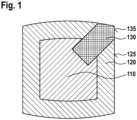
- a mandrel for producing a hollow composite component of a wind turbine rotor blade, the mandrel including a core of a first material, an outer layer of a second material arranged radially outward of the core, the second material being more compressible than the first material, and a first intensifier member for intensifying a pressure on a first inner area of a lay-up, the first intensifier member being arranged at least partially radially outward of the core, wherein a first outer surface of the first intensifier member and a second outer surface of the outer layer, together, forms a defined shape corresponding to a desired inner shape of at least a portion of the hollow composite component.
- the mandrel includes a core 110 of a first material and an outer layer 120 of a second material.
- the first material and the second material are compressible materials.
- the second material is more compressible than the first material.
- a compressible material may be understood as a material having a non-compressed state and a compressed state.
- a compressible material may be understood as a material capable of being in a non-compressed state, in which the compressible material forms a defined shape.
- a compressible material may be understood as a material capable of being in a non-compressed state, in which the compressible material has sufficient rigidity to maintain a defined shape during lay up and curing of fiber reinforcement material placed around the mandrel.
- a compressible material may be understood as a material capable of being transformed into a compressed state upon application of a vacuum thereto.
- a compressible material may be understood as a material having sufficient elasticity to return to a non-compressed state upon release of the vacuum applied thereto.
- the pressure on the first inner area of the lay-up may be understood as a compressive force on the lay-up. It may be understood that a mould or a part of the mould, around the mandrel and the lay-up, in combination with a vacuum applied to the lay-up enables the pressure or compressive force to the first inner area of the lay-up. It may be understood that the depression or the opening of the core 110 acts as cylinder walls.
- 'Lay-up' may be understood as material(s) forming or for forming at least a portion of the hollow composite component.
- 'lay-up' may be understood as fiber fabric and/or composite materials.
- the hollow composite component is a part of a spar beam component, a spar beam component, a part of a spar beam, or a spar beam.
- a hollow composite component, in particular a spar beam as described herein, may be understood as being manufactured to become an inner part of a wind turbine rotor blade.
- 'Lay-up' may be understood to comprise or contain material in a state prior to final or complete curing, for example, comprising or containing uncured material, pre-cured material, and/or partially-cured material.
- 'Lay-up' may be understood as layers of material.
- 'lay-up' may be understood to include plies, for example, mineral plies, polymer plies, glass plies, metallic plies, carbon plies).
- 'Lay-up' may be understood to include fibers, for example, mineral fibers, polymer fibers, glass fibers, metallic fibers, carbon fibers.
- polymer fiber may include aromatic polyamides, polyethylene, polyurethane and/or aramide fibers. It may be understood that the fibers may be in the form of unidirectional or multidirectional fibers, prepregs, fiber boards, or fiber mats.
- 'lay-up' includes dry glass/carbon fabrics, and/or pre-preg.
- 'lay-up' includes pre-fabricated material(s).
- first intensifier member for intensifying a pressure' may be understood as a first intensifier member 130 for providing a higher pressure or a larger force than a pressure or a force provided if the first intensifier member is replaced by a member of the second material.
- the pressure or the force provided by the extended outer layer in the position in which the first intensifier member 130 is otherwise arranged is less than the pressure or the force provided by the first intensifier member 130 in said position.
- the first outer surface 135 of the first intensifier member 130 is a surface configured to be proximate to the first inner area of the lay-up. In an example, the first outer surface 135 of the first intensifier member 130 is arranged (most) distal from the core.
- the second outer surface 125 of the outer layer 120 is a surface configured to be proximate to a second inner area of the lay-up. It may be understood that the second inner area of the lay-up is proximate to the first inner area of the lay-up.
- first outer surface 135 of the first intensifier member 130 and the second outer surface 125 of the outer layer 120 share a common edge.
- the defined shape formed by the first outer surface 135 of the first intensifier member 130 and the second outer surface 125 of the outer layer 120, together), and the desired shape (of the at least a portion of the hollow composite component) is when the lay-up is laid-up on the mandrel, in particular, during (in-mould) curing process.
- the defined shape (of the mandrel) and the desired shape (of the hollow composite component) are of the mandrel and hollow composite component, respectively, during (in-mould) curing process.
- the second inner area of the lay-up and the first inner area of the lay-up share a common edge.
- lay-up, laid-up on the mandrel, including the first outer surface 135 of the first intensifier member 130 and the second outer surface 125 of the outer layer 120, is cured to form at least a portion of the hollow composite component, wherein the at least a portion of the hollow composite component has the desired inner shape corresponding to the defined shape formed by the first outer surface 135 of the first intensifier member 130 and the second outer surface 125 of the outer layer 120.
- the performance of the mandrel is improved with respect to a desired shape of the hollow composite component, having a defined feature, e.g. a corner. Accordingly, a desired shape of the hollow composite component can be better achieved. Accordingly, undesirable effects, such as bridging, may be better avoided.
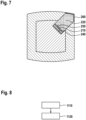
- the first intensifier member 130 comprises a hollow portion 210 expandable by a pressurizing fluid.
- the hollow portion 210 is inflatable.
- the hollow portion 210 may be understood as an inflatable portion.
- a pressurizing fluid is a gas (e.g. air, nitrogen), or a liquid (e.g. water).
- the hollow portion 210 is arranged proximate to the core 110, and/or wherein the hollow portion 210 is at least partially surrounded by the core 110.
- the hollow portion is arranged at a first end of the first intensifier member 130, proximate to the core 110.
- the core 110 comprises a depression or an opening, e.g. a recess, a cavity, a slot, a groove or a channel.
- the depression of the core 110 or the opening of the core 110 is configured for holding the first intensifier member 130.
- the depression or opening of the core 110 has an inner shape complementing a shape of a portion of the first intensifier member 130.
- the depression or the opening is oriented in a direction in which the intensified pressure is to be applied to the first inner area of the lay-up.
- the depression or the opening is oriented in a direction of the first inner area of the lay-up.
- an axis of the depression or the opening of the core 110 is oriented in a direction of the first inner area of the lay-up, the axis being in a cross-sectional plane of the core 110, the axis preferably being an axis of symmetry of the depression or the opening.
- the hollow portion 210 is fluidly isolated from the core 110 and rest of the first intensifier member 130. In an example, the hollow portion 210 is fluidly isolated from the rest of the first intensifier member 130 and/or from the core 110 and/or the outer layer 120.
- the hollow portion forms a fluidly sealed volume, apart from a port.
- the port can be in an open state, e.g. to allow pressurizing fluid to pass through the port, and in a closed state, e.g. to block pressurizing fluid from passing through the port.
- the first intensifier member 130 is less compressible or more rigid relative to the outer layer 120. In an example, the first intensifier member comprises a material less compressible than the second material of the outer layer 120.
- a pressure acting on the first inner area of the lay-up proximate to the first intensifier member 130 is intensified relative to (or is larger than) a pressure acting on the second inner area of the lay-up proximate to the outer layer 120, during the curing process, e.g. curing in an autoclave.
- the performance of the mandrel is improved with respect to a desired shape of the hollow composite component, having a defined feature, e.g. a corner. Accordingly, a desired shape of the hollow composite component can be better achieved. Accordingly, undesirable effects, such as bridging, may be better avoided.
- the hollow portion 210 is a 2 inch thick discharge hose providing radial expansion of 1.25 inch.
- the hollow portion 210 comprises at least one from the following group: drop stitches 410; 420, continuous fibers, and reinforcement, for defining a shape of the hollow portion 210 in an expanded state 320.
- the hollow portion 210 in an expanded state 320, has a defined shape for intensifying the pressure on the first inner area of the lay-up.
- the first inner area of the lay-up comprises a defined feature, e.g. a corner.
- the hollow portion 210 has a shape, e.g. in cross-section, circular or triangular, and/or is arranged, such that, when in an expanded state 320, intensifies the pressure on the first inner area of the lay-up, at the point of smallest radius, or along the axis of, of the defined feature, e.g. at the apex of the corner.
- the first material of the core 110 may be a foam material, for example closed-cell foam.
- the first material of the core 110 may be (further comprising) a non-compressible material, such as a plastic or wood core.
- the core 110 may be rigid.
- the core 110 may be hollow, e.g. having an outer (rigid) structure, with an empty inner portion, or with an inner portion that is filled with a fluid, in particular air.
- the empty inner portion may form more than 50%, by volume, of the core 110.
- the first material may be at least one of the following: polymeric, rubber, polyethylene (EPE, XLPE), EVA, polypropylene, polystyrene, Closed Cell EPDM Foam Rubber, preferably crosslinked polyethylene; density of at least 1 lb. per cubic foot, preferably at least 2 lbs. per cubic foot; density of at most 4 lbs. per cubit foot, preferably at most 3 lbs. per cubic foot; as a particular example: Minicell ® L200 or cross-linked polyethylene.
- the first intensifier member 130 comprises a first intermediate portion 220 of a third material less compressible than the second material of the outer layer 120, preferably wherein the first intermediate portion 220 comprises closed shell foam.
- first intermediate portion 220 is less compressible or more rigid, relative to the outer layer 120, and/or relative to the core 110.
- the first intermediate portion 220 enables the transmission of the pressure intensification on the first inner area of the lay-up.
- the first intensifier member 130 comprises a second intermediate portion 230 less compressible than the first intermediate portion 220, the second intermediate portion 230 being arranged proximate to the first outer surface 135 or having a surface forming the first outer surface 135.
- the second intermediate portion 230 is incompressible or rigid. It may be understood that the second intermediate portion 230 is less compressible or more rigid, relative to the first intermediate portion, relative to the core 110, and/or relative to the outer layer 120.
- the second intermediate portion 230 has an outer surface of a defined shape corresponding to the desired inner shape of at least a portion of the hollow composite component.
- the second intermediate portion 230 enables the pressure intensification on the first inner area of the lay-up.
- first intensifier members 130 there may be a plurality of first intensifier members 130.
- the at least one further intensifier member may be according to embodiments and examples of the first intensifier member 130 as described herein.
- the core 110 comprises closed shell foam, and/or wherein the outer layer 120 comprises open shell foam.
- the second material of the outer layer 120 may be a foam material, for example open-cell foam.
- the second material is more compressible than the first material.
- the second material may have a lower density than the first material.
- the second material may be less rigid than the first material.
- the second material may be at least one of the following: polymeric, rubber, polyurethane, reticulated polyurethane, PVC, nitrile, EPDM; density of at least 1 lb. per cubic foot, preferably at least 2 lbs. per cubic foot; density of at most 4 lbs. per cubit foot, preferably at most 3 lbs. per cubic foot; as a particular example: Lux-HQ ® or Lux ® foam.
- the at least one further outer layer may be according to embodiments and examples of the outer layer 120 as described herein.
- the core 110 may be understood to be a support (or a base) for the outer layer 120 and/or the first intensifier member 130.
- the outer layer 120 and/or the first intensifier member 130 are/is arranged radially outward of the core 110.
- the outer layer 120 and/or the first intensifier member 130 are/is arranged on the core 110.
- the outer layer 120 and/or the first intensifier member 130 are/is bonded to the core 110, e.g. using rubber glue. In an example, the outer layer 120 and the first intensifier member 130 are bonded to each other, e.g. using rubber glue.
- the first intensifier member 130 is configured for intensifying a pressure on a first inner area of a lay-up.
- the first intensifier member 130 is arranged at least partially radially outward of the core.
- the first intensifier member 130 has an inner radial position within a radial extent of the core.
- the first intensifier member 130 is arranged extending from a radial position within a radial extent of the core, or from an outer surface of the core 110.
- the core acts as a constraint to control the direction of force effected by the first intensifier member 130 on the lay up (on the first inner area of the lay-up).
- an outer skin portion 260 of the first intensifier member 130 forming the first outer surface 135 is more rigid than the first intermediate portion 220 of the first intensifier member 130.
- an outer skin portion 260 of the first intensifier member 130 forming the first outer surface 135 is more rigid than a portion of the outer layer 120 forming the second outer surface 125 of the outer layer 120.
- the outer skin portion 260 has a rigidity module at least an order of magnitude larger than a rigidity modulus of the first intermediate portion 220, the core 110, and/or the outer layer 120.
- the outer skin portion 260 is of a rigid material, e.g. fiber-reinforced plastic. In an example, the outer skin portion 260 is incompressible or rigid.
- the outer skin portion 260 has an outer surface of a defined shape corresponding to the desired inner shape of at least a portion of the hollow composite component.
- the outer skin portion 260 enables the pressure intensification on the first inner area of the lay-up.
- the first outer surface 135 of the first intensifier member 130 comprises a feature with a radius smaller than a radius of any feature of the second outer surface 125 of the outer layer 120.
- the first outer surface 135 of the first intensifier member 130 is a discontinuous surface or a non-flat surface.
- the performance of the mandrel is improved with respect to a desired shape of the hollow composite component, having a defined feature, e.g. a feature with a small radius, e.g. a corner. Accordingly, a desired shape of the hollow composite component can be better achieved. Accordingly, undesirable effects, such as bridging, may be better avoided.
- a first rigid surface portion 240 is arranged on a radially proximal side of the hollow portion 210.
- a second rigid surface portion 250 is arranged on a radially distal side of the hollow portion 210.
- first rigid surface portion 240 and the second rigid surface portion 250 enables the directed transmission of the pressure intensification on the first inner area of the lay-up.
- the term 'radially proximal' may be understood as proximate to the center (of the core 110), in a radial direction, or proximate to the core 110, in a radial direction.
- the term ⁇ radially distal' may be understood distant from the center (of the core 110), in a radial direction, or distant from the core 110, in a radial direction.
- ⁇ radial direction' may be understood as a direction extending outward from a center of the core 110 or from a center of the mandrel, in a cross-sectional plane of the core 110 or in a cross-sectional plane of the mandrel.
- 'radial' may be understood to be along a direction extending outward from a center of the core 110 or from a center of the mandrel, in a cross-sectional plane of the core 110 or in a cross-sectional plane of the mandrel.
- a thickness dimension of the outer layer 120 is configured to enable extraction of the mandrel from the hollow composite component, and/or wherein a thickness dimension of the outer layer 120 is configured based on a compressibility of the second material of the outer layer 120 and a geometry of the hollow composite component.
- the compressed mandrel having a reduced cross-sectional size, particularly due to the compression of the outer layer 120, can be withdrawn from the hollow composite structure, post-curing. It may be understood that the mandrel could not be withdrawn from the hollow composite structure, post-curing, when the mandrel is not compressed, i.e. when the mandrel is in a non-compressed state.
- a compressible mandrel may be understood to enable extraction of the mandrel from the hollow composite component, post-curing. Since a compressible mandrel is at particular risk of undesirable effects, such as bridging, due to its compressibility, a compressible mandrel, provided with a pressure intensifier member, as described herein, enables a compressible mandrel to achieve a shape definition similar to a rigid mandrel, yet still having the benefits of a compressible mandrel.
- a method for producing a hollow composite component of a wind turbine rotor blade using a mandrel as described herein, the method including placing the lay-up around the mandrel within a mould, and performing an in-mould curing process.
- Placing the lay-up around the mandrel within a mould 1110 may be understood as a fiber material lay up process.
- the lay-up is laid-up in a mould or in a part of a mould.
- a mandrel is arranged on the laid-up lay-up.
- the laid-up lay-up with the mandrel arranged atop is arranged around the mandrel.
- Performing an in-mould curing process 1120 may be understood as following a resin infusion process. It may be understood that a resin infusion process is performed after drawing, in the mould, a vacuum.
- the method for producing a hollow composite component of a wind turbine rotor blade comprises activating the first intensifier member 1210, at least during the in-mould curing process, preferably before the in-mould curing process.
- activating the first intensifier member 1210 comprises fluidly pressurizing a hollow portion of the first intensifier member.
- a gas or liquid pump may be fluidly connected to the hollow portion 210.
- the hollow portion may be pressurized using the gas or liquid pump.
- fluidly pressurizing a hollow portion of the first intensifier member comprises pumping a gas or liquid into the hollow portion of the first intensifier member.
- the hollow portion is in a fluidly pressurized state or expanded state when a pressure of the fluid in the hollow portion reaches an upper pressure limit of the hollow portion.
- the method for producing a hollow composite component of a wind turbine rotor blade comprises extracting the mandrel 1240 from the composite component.
- extracting the mandrel 1240 comprises deactivating the first intensifier member 1220 and drawing a vacuum on the mandrel 1230.
- deactivating the first intensifier member 1220 comprises releasing fluid pressure to the first intensifier member, after the in-mould curing process.
- activating the first intensifier member 1210 comprises effecting a first pressure, by the first intensifier member, on the first inner area of the lay-up, that is higher than a second pressure, by the outer layer, on a second inner area of the lay-up that is proximate to the first inner area.
- the pressure is intensified at least during curing of the lay-up. Accordingly, a desired shape of the hollow composite component can be better achieved.
- a hollow composite component of a wind turbine rotor blade manufactured using a mandrel as described herein.
- a hollow composite component of a wind turbine rotor blade as described herein is (e.g., a part of) a spar beam component, e.g. first spar member 510 or third spar member 610.
- the first spar member 510 is a hollow spar member, integrated into the structure of the wind turbine rotor blade 530.
- the first spar member 510 is composed of a plurality of components, including at least one hollow composite component.
- the third spar member 610 is a hollow spar member arranged within a receiving section, e.g. first spar member 510, of a wind turbine rotor blade 530.
- the second spar member 520 may include a hollow composite component, for example a hollow spar web which may be arranged between spar caps.
- a wind turbine rotor blade 530 may be as depicted in Fig. 10 .
- a core is formed of a harder, less compressible foam.
- the mandrel is cut to the profile of the inner mould line of the hollow composite component, minus the offset for the bulked lay-up.
- the mandrel is also offset to allow a layer of more compressible open cell forming the outer layer.
- this outer layer thickness is defined by the amount of compression needed to extract the mandrel from the hollow composite component.
- the thickness of this outer layer is in accordance or based on the geometry of the hollow composite component.
- a pressurizable member in the areas of the lay-up that need higher compression, is provided.
- this pressurizable member may have a constrained shape when pressured or the movement of which may be constrained to a specific direction, i.e. a vector of force is provided.
- the core is used to control the vector of force and orient the vector of force at the desired location of the lay-up.
- the outer layer is compressible.
- the foam is compressed, and the mandrel size is reduced, allowing the mandrel to be extracted from the hollow composite component in which the mandrel would otherwise be die locked.
- a less compressive component makes the core of the mandrel.
- the core acts as a support for the compressible layers as well as a constraint that control the direction in which the compressive force is applied to the lay up.
- the slot in the core is oriented in the direction in which the pressure is applied to the laminate.
- the slot in the core acts as cylinder walls.
- the slot in the core is filled with an expandable element that provides directional movement and/or pressure.
- the expandable element is covered by harder and/or less compressible foam, or even solid rigid components if needed, to pinpoint the area that needs to be compressed.
- an outside layer is made of compressible open cell material that can be considerable reduced in size under compression or vacuum allowing the extraction of the mandrel out of an otherwise die locked shape.
- the mandrel includes foams of different firmness.
- a first foam is provided for the all-around cover and a second foam firmer than the first foam is provided for the corners.
- a combination of open-cell foam and closed-cell foam is provided for the corners.
- a collapsible mandrel beneficially facilitates extraction.
- a mandrel incorporating intensifiers which may be pneumatically activated and which can provide controlled linear movement to intensify pressure in specific areas such as corners or other geometry that necessitate very good definition is beneficial.
- a mandrel which controls the direction of force by intensifiers. It is beneficial to use hollow shapes that can be pressurized with a gas or liquid but which is constrained to a final shape when pressurized. This can beneficially be achieved by internal reinforcement, fabric, or drop stitches that define the final pressurized shape and prevent expansion in directions where no compression is wanted or needed.
- a solid mandrel having (mechanical) activators to apply pressure in specific areas are generally very complex, less flexible and much less resource efficient.
Landscapes
- Engineering & Computer Science (AREA)
- Mechanical Engineering (AREA)
- Chemical & Material Sciences (AREA)
- Composite Materials (AREA)
- Moulding By Coating Moulds (AREA)
Priority Applications (6)
| Application Number | Priority Date | Filing Date | Title |
|---|---|---|---|
| ES22161665T ES3023346T3 (en) | 2022-03-11 | 2022-03-11 | Mandrel for producing a hollow composite component of a wind turbine rotor blade and method using the mandrel |
| EP22161665.9A EP4241963B1 (en) | 2022-03-11 | 2022-03-11 | Mandrel for producing a hollow composite component of a wind turbine rotor blade and method using the mandrel |
| DK22161665.9T DK4241963T3 (da) | 2022-03-11 | 2022-03-11 | Dorn til fremstilling af et hult kompositelement af en vindmølle-rotorvinge og fremgangsmåde ved brug af dornen |
| PL22161665.9T PL4241963T3 (pl) | 2022-03-11 | 2022-03-11 | Trzpień do wytwarzania pustego w środku elementu kompozytowego łopaty wirnika turbiny wiatrowej i sposób używania tego trzpienia |
| PCT/EP2023/056020 WO2023170211A1 (en) | 2022-03-11 | 2023-03-09 | Mandrel for producing a hollow composite component of a wind turbine rotor blade |
| CN202380039414.2A CN119173375A (zh) | 2022-03-11 | 2023-03-09 | 用于生产风力涡轮机转子叶片的中空复合构件的心轴 |
Applications Claiming Priority (1)
| Application Number | Priority Date | Filing Date | Title |
|---|---|---|---|
| EP22161665.9A EP4241963B1 (en) | 2022-03-11 | 2022-03-11 | Mandrel for producing a hollow composite component of a wind turbine rotor blade and method using the mandrel |
Publications (2)
| Publication Number | Publication Date |
|---|---|
| EP4241963A1 EP4241963A1 (en) | 2023-09-13 |
| EP4241963B1 true EP4241963B1 (en) | 2025-02-12 |
Family
ID=80775087
Family Applications (1)
| Application Number | Title | Priority Date | Filing Date |
|---|---|---|---|
| EP22161665.9A Active EP4241963B1 (en) | 2022-03-11 | 2022-03-11 | Mandrel for producing a hollow composite component of a wind turbine rotor blade and method using the mandrel |
Country Status (6)
| Country | Link |
|---|---|
| EP (1) | EP4241963B1 (pl) |
| CN (1) | CN119173375A (pl) |
| DK (1) | DK4241963T3 (pl) |
| ES (1) | ES3023346T3 (pl) |
| PL (1) | PL4241963T3 (pl) |
| WO (1) | WO2023170211A1 (pl) |
Families Citing this family (1)
| Publication number | Priority date | Publication date | Assignee | Title |
|---|---|---|---|---|
| US20240391199A1 (en) * | 2021-08-25 | 2024-11-28 | Lm Wind Power A/S | Mandrel device for manufacturing a segmented wind turbine blade |
Family Cites Families (2)
| Publication number | Priority date | Publication date | Assignee | Title |
|---|---|---|---|---|
| WO2005070668A1 (en) * | 2004-01-23 | 2005-08-04 | Covess Nv | Hollow composite body of fiber reinforced thermoplastic material |
| MX2021006487A (es) | 2018-12-11 | 2021-11-25 | Gen Electric | Metodo para fabricar una estructura compuesta hueca, particularmente una viga para un aspa de rotor de turbina eolica y un mandril asociado. |
-
2022
- 2022-03-11 EP EP22161665.9A patent/EP4241963B1/en active Active
- 2022-03-11 PL PL22161665.9T patent/PL4241963T3/pl unknown
- 2022-03-11 ES ES22161665T patent/ES3023346T3/es active Active
- 2022-03-11 DK DK22161665.9T patent/DK4241963T3/da active
-
2023
- 2023-03-09 WO PCT/EP2023/056020 patent/WO2023170211A1/en not_active Ceased
- 2023-03-09 CN CN202380039414.2A patent/CN119173375A/zh active Pending
Also Published As
| Publication number | Publication date |
|---|---|
| WO2023170211A1 (en) | 2023-09-14 |
| ES3023346T3 (en) | 2025-05-30 |
| EP4241963A1 (en) | 2023-09-13 |
| PL4241963T3 (pl) | 2025-05-19 |
| CN119173375A (zh) | 2024-12-20 |
| DK4241963T3 (da) | 2025-05-12 |
Similar Documents
| Publication | Publication Date | Title |
|---|---|---|
| US8303882B2 (en) | Apparatus and method of making composite material articles | |
| EP3394430B1 (en) | Wind turbine blades and related methods of manufacturing | |
| US8945325B2 (en) | Methods and systems for forming integral composite parts with a SMP apparatus | |
| EP0650825B1 (en) | Method for forming a unitary fibre-reinforced composite panel structure | |
| WO2012064446A2 (en) | Reconfigurable shape memory polymer tooling supports | |
| US20120286457A1 (en) | Methods and systems for fabricating composite stiffeners with a rigid/malleable smp apparatus | |
| US12466143B2 (en) | Method for manufacturing fiber-reinforced resin structure | |
| JP4639549B2 (ja) | Frpの製造方法 | |
| EP4241963B1 (en) | Mandrel for producing a hollow composite component of a wind turbine rotor blade and method using the mandrel | |
| WO2021262927A1 (en) | Method for manufacturing a composite structure and composite structure | |
| US20140360665A1 (en) | Reflector manufactured using multiple use precision extractable tooling | |
| US20060280927A1 (en) | Lightweight composite fairing bar an method for manufacturing the same | |
| CN112672876A (zh) | 纤维复合半成品、纤维复合构件、转子叶片元件、转子叶片和风能设施以及用于制造纤维复合半成品的方法和用于制造纤维复合构件的方法 | |
| CN113165284A (zh) | 用于制造空心复合结构、特别是用于风力涡轮转子叶片的翼梁式梁的方法以及相关联的心轴 | |
| CN113382849B (zh) | 用于制造纤维增强聚合物复合梁、特别是用于风力涡轮转子叶片的翼梁式梁的方法 | |
| CN104890254A (zh) | 用于制造风力涡轮的部件的方法 | |
| JP2003314431A (ja) | 風車翼 | |
| US20250354536A1 (en) | A web, a wind turbine blade and a manufacturing method thereof | |
| JP4645775B2 (ja) | Frpの製造方法 | |
| CA3122754C (en) | Method for manufacturing a fiber reinforced polymer composite beam, particularly a spar beam for a wind turbine rotor blade | |
| US20230356484A1 (en) | A method of manufacturing a wind turbine blade part with a flow-enhancing mat | |
| JP2003311755A (ja) | 中空サンドイッチ部材の製造方法、及び中空サンドイッチ部材 | |
| WO2013096381A1 (en) | Reflector manufactured using multiple use precision extractable tooling | |
| HK1207841B (zh) | 采用pmi泡沫芯的拉芯方法 |
Legal Events
| Date | Code | Title | Description |
|---|---|---|---|
| PUAI | Public reference made under article 153(3) epc to a published international application that has entered the european phase |
Free format text: ORIGINAL CODE: 0009012 |
|
| STAA | Information on the status of an ep patent application or granted ep patent |
Free format text: STATUS: THE APPLICATION HAS BEEN PUBLISHED |
|
| AK | Designated contracting states |
Kind code of ref document: A1 Designated state(s): AL AT BE BG CH CY CZ DE DK EE ES FI FR GB GR HR HU IE IS IT LI LT LU LV MC MK MT NL NO PL PT RO RS SE SI SK SM TR |
|
| STAA | Information on the status of an ep patent application or granted ep patent |
Free format text: STATUS: REQUEST FOR EXAMINATION WAS MADE |
|
| 17P | Request for examination filed |
Effective date: 20240312 |
|
| RBV | Designated contracting states (corrected) |
Designated state(s): AL AT BE BG CH CY CZ DE DK EE ES FI FR GB GR HR HU IE IS IT LI LT LU LV MC MK MT NL NO PL PT RO RS SE SI SK SM TR |
|
| GRAP | Despatch of communication of intention to grant a patent |
Free format text: ORIGINAL CODE: EPIDOSNIGR1 |
|
| STAA | Information on the status of an ep patent application or granted ep patent |
Free format text: STATUS: GRANT OF PATENT IS INTENDED |
|
| INTG | Intention to grant announced |
Effective date: 20240905 |
|
| GRAS | Grant fee paid |
Free format text: ORIGINAL CODE: EPIDOSNIGR3 |
|
| GRAA | (expected) grant |
Free format text: ORIGINAL CODE: 0009210 |
|
| STAA | Information on the status of an ep patent application or granted ep patent |
Free format text: STATUS: THE PATENT HAS BEEN GRANTED |
|
| P01 | Opt-out of the competence of the unified patent court (upc) registered |
Free format text: CASE NUMBER: APP_66493/2024 Effective date: 20241216 |
|
| AK | Designated contracting states |
Kind code of ref document: B1 Designated state(s): AL AT BE BG CH CY CZ DE DK EE ES FI FR GB GR HR HU IE IS IT LI LT LU LV MC MK MT NL NO PL PT RO RS SE SI SK SM TR |
|
| REG | Reference to a national code |
Ref country code: GB Ref legal event code: FG4D |
|
| REG | Reference to a national code |
Ref country code: CH Ref legal event code: EP |
|
| REG | Reference to a national code |
Ref country code: DE Ref legal event code: R096 Ref document number: 602022010349 Country of ref document: DE |
|
| REG | Reference to a national code |
Ref country code: IE Ref legal event code: FG4D |
|
| PGFP | Annual fee paid to national office [announced via postgrant information from national office to epo] |
Ref country code: DE Payment date: 20250218 Year of fee payment: 4 |
|
| PGFP | Annual fee paid to national office [announced via postgrant information from national office to epo] |
Ref country code: AT Payment date: 20250417 Year of fee payment: 4 |
|
| PGFP | Annual fee paid to national office [announced via postgrant information from national office to epo] |
Ref country code: FR Payment date: 20250319 Year of fee payment: 4 |
|
| REG | Reference to a national code |
Ref country code: DK Ref legal event code: T3 Effective date: 20250506 |
|
| REG | Reference to a national code |
Ref country code: ES Ref legal event code: FG2A Ref document number: 3023346 Country of ref document: ES Kind code of ref document: T3 Effective date: 20250530 |
|
| REG | Reference to a national code |
Ref country code: NL Ref legal event code: MP Effective date: 20250212 |
|
| PG25 | Lapsed in a contracting state [announced via postgrant information from national office to epo] |
Ref country code: RS Free format text: LAPSE BECAUSE OF FAILURE TO SUBMIT A TRANSLATION OF THE DESCRIPTION OR TO PAY THE FEE WITHIN THE PRESCRIBED TIME-LIMIT Effective date: 20250512 |
|
| PG25 | Lapsed in a contracting state [announced via postgrant information from national office to epo] |
Ref country code: FI Free format text: LAPSE BECAUSE OF FAILURE TO SUBMIT A TRANSLATION OF THE DESCRIPTION OR TO PAY THE FEE WITHIN THE PRESCRIBED TIME-LIMIT Effective date: 20250212 |
|
| PGFP | Annual fee paid to national office [announced via postgrant information from national office to epo] |
Ref country code: PL Payment date: 20250320 Year of fee payment: 4 |
|
| PGFP | Annual fee paid to national office [announced via postgrant information from national office to epo] |
Ref country code: ES Payment date: 20250403 Year of fee payment: 4 Ref country code: DK Payment date: 20250513 Year of fee payment: 4 |
|
| REG | Reference to a national code |
Ref country code: LT Ref legal event code: MG9D |
|
| PG25 | Lapsed in a contracting state [announced via postgrant information from national office to epo] |
Ref country code: IS Free format text: LAPSE BECAUSE OF FAILURE TO SUBMIT A TRANSLATION OF THE DESCRIPTION OR TO PAY THE FEE WITHIN THE PRESCRIBED TIME-LIMIT Effective date: 20250612 Ref country code: NO Free format text: LAPSE BECAUSE OF FAILURE TO SUBMIT A TRANSLATION OF THE DESCRIPTION OR TO PAY THE FEE WITHIN THE PRESCRIBED TIME-LIMIT Effective date: 20250512 |
|
| PG25 | Lapsed in a contracting state [announced via postgrant information from national office to epo] |
Ref country code: NL Free format text: LAPSE BECAUSE OF FAILURE TO SUBMIT A TRANSLATION OF THE DESCRIPTION OR TO PAY THE FEE WITHIN THE PRESCRIBED TIME-LIMIT Effective date: 20250212 |
|
| PG25 | Lapsed in a contracting state [announced via postgrant information from national office to epo] |
Ref country code: HR Free format text: LAPSE BECAUSE OF FAILURE TO SUBMIT A TRANSLATION OF THE DESCRIPTION OR TO PAY THE FEE WITHIN THE PRESCRIBED TIME-LIMIT Effective date: 20250212 |
|
| PG25 | Lapsed in a contracting state [announced via postgrant information from national office to epo] |
Ref country code: PT Free format text: LAPSE BECAUSE OF FAILURE TO SUBMIT A TRANSLATION OF THE DESCRIPTION OR TO PAY THE FEE WITHIN THE PRESCRIBED TIME-LIMIT Effective date: 20250612 Ref country code: LV Free format text: LAPSE BECAUSE OF FAILURE TO SUBMIT A TRANSLATION OF THE DESCRIPTION OR TO PAY THE FEE WITHIN THE PRESCRIBED TIME-LIMIT Effective date: 20250212 |
|
| PG25 | Lapsed in a contracting state [announced via postgrant information from national office to epo] |
Ref country code: BG Free format text: LAPSE BECAUSE OF FAILURE TO SUBMIT A TRANSLATION OF THE DESCRIPTION OR TO PAY THE FEE WITHIN THE PRESCRIBED TIME-LIMIT Effective date: 20250212 Ref country code: GR Free format text: LAPSE BECAUSE OF FAILURE TO SUBMIT A TRANSLATION OF THE DESCRIPTION OR TO PAY THE FEE WITHIN THE PRESCRIBED TIME-LIMIT Effective date: 20250513 |
|
| PG25 | Lapsed in a contracting state [announced via postgrant information from national office to epo] |
Ref country code: AT Free format text: LAPSE BECAUSE OF FAILURE TO SUBMIT A TRANSLATION OF THE DESCRIPTION OR TO PAY THE FEE WITHIN THE PRESCRIBED TIME-LIMIT Effective date: 20250212 |
|
| PGFP | Annual fee paid to national office [announced via postgrant information from national office to epo] |
Ref country code: TR Payment date: 20250512 Year of fee payment: 4 |
|
| REG | Reference to a national code |
Ref country code: AT Ref legal event code: MK05 Ref document number: 1765696 Country of ref document: AT Kind code of ref document: T Effective date: 20250212 |
|
| PG25 | Lapsed in a contracting state [announced via postgrant information from national office to epo] |
Ref country code: SE Free format text: LAPSE BECAUSE OF FAILURE TO SUBMIT A TRANSLATION OF THE DESCRIPTION OR TO PAY THE FEE WITHIN THE PRESCRIBED TIME-LIMIT Effective date: 20250212 |
|
| PG25 | Lapsed in a contracting state [announced via postgrant information from national office to epo] |
Ref country code: SM Free format text: LAPSE BECAUSE OF FAILURE TO SUBMIT A TRANSLATION OF THE DESCRIPTION OR TO PAY THE FEE WITHIN THE PRESCRIBED TIME-LIMIT Effective date: 20250212 |
|
| PG25 | Lapsed in a contracting state [announced via postgrant information from national office to epo] |
Ref country code: IT Free format text: LAPSE BECAUSE OF FAILURE TO SUBMIT A TRANSLATION OF THE DESCRIPTION OR TO PAY THE FEE WITHIN THE PRESCRIBED TIME-LIMIT Effective date: 20250212 |
|
| PG25 | Lapsed in a contracting state [announced via postgrant information from national office to epo] |
Ref country code: EE Free format text: LAPSE BECAUSE OF FAILURE TO SUBMIT A TRANSLATION OF THE DESCRIPTION OR TO PAY THE FEE WITHIN THE PRESCRIBED TIME-LIMIT Effective date: 20250212 Ref country code: CZ Free format text: LAPSE BECAUSE OF FAILURE TO SUBMIT A TRANSLATION OF THE DESCRIPTION OR TO PAY THE FEE WITHIN THE PRESCRIBED TIME-LIMIT Effective date: 20250212 |
|
| REG | Reference to a national code |
Ref country code: CH Ref legal event code: H13 Free format text: ST27 STATUS EVENT CODE: U-0-0-H10-H13 (AS PROVIDED BY THE NATIONAL OFFICE) Effective date: 20251023 |
|
| PG25 | Lapsed in a contracting state [announced via postgrant information from national office to epo] |
Ref country code: RO Free format text: LAPSE BECAUSE OF FAILURE TO SUBMIT A TRANSLATION OF THE DESCRIPTION OR TO PAY THE FEE WITHIN THE PRESCRIBED TIME-LIMIT Effective date: 20250212 |
|
| PG25 | Lapsed in a contracting state [announced via postgrant information from national office to epo] |
Ref country code: SK Free format text: LAPSE BECAUSE OF FAILURE TO SUBMIT A TRANSLATION OF THE DESCRIPTION OR TO PAY THE FEE WITHIN THE PRESCRIBED TIME-LIMIT Effective date: 20250212 |
|
| REG | Reference to a national code |
Ref country code: DE Ref legal event code: R097 Ref document number: 602022010349 Country of ref document: DE |
|
| PG25 | Lapsed in a contracting state [announced via postgrant information from national office to epo] |
Ref country code: LU Free format text: LAPSE BECAUSE OF NON-PAYMENT OF DUE FEES Effective date: 20250311 |
|
| REG | Reference to a national code |
Ref country code: BE Ref legal event code: MM Effective date: 20250331 |
|
| PLBE | No opposition filed within time limit |
Free format text: ORIGINAL CODE: 0009261 |
|
| STAA | Information on the status of an ep patent application or granted ep patent |
Free format text: STATUS: NO OPPOSITION FILED WITHIN TIME LIMIT |
|
| PG25 | Lapsed in a contracting state [announced via postgrant information from national office to epo] |
Ref country code: MC Free format text: LAPSE BECAUSE OF FAILURE TO SUBMIT A TRANSLATION OF THE DESCRIPTION OR TO PAY THE FEE WITHIN THE PRESCRIBED TIME-LIMIT Effective date: 20250212 |
|
| PG25 | Lapsed in a contracting state [announced via postgrant information from national office to epo] |
Ref country code: BE Free format text: LAPSE BECAUSE OF NON-PAYMENT OF DUE FEES Effective date: 20250331 |
|
| PG25 | Lapsed in a contracting state [announced via postgrant information from national office to epo] |
Ref country code: CH Free format text: LAPSE BECAUSE OF NON-PAYMENT OF DUE FEES Effective date: 20250331 |
|
| PG25 | Lapsed in a contracting state [announced via postgrant information from national office to epo] |
Ref country code: IE Free format text: LAPSE BECAUSE OF NON-PAYMENT OF DUE FEES Effective date: 20250311 |
|
| 26N | No opposition filed |
Effective date: 20251113 |