EP4241932A1 - Seal affixing system - Google Patents
Seal affixing system Download PDFInfo
- Publication number
- EP4241932A1 EP4241932A1 EP23156603.5A EP23156603A EP4241932A1 EP 4241932 A1 EP4241932 A1 EP 4241932A1 EP 23156603 A EP23156603 A EP 23156603A EP 4241932 A1 EP4241932 A1 EP 4241932A1
- Authority
- EP
- European Patent Office
- Prior art keywords
- seal
- adsorption
- suction
- affixing
- end effector
- Prior art date
- Legal status (The legal status is an assumption and is not a legal conclusion. Google has not performed a legal analysis and makes no representation as to the accuracy of the status listed.)
- Granted
Links
Images


Classifications
-
- B—PERFORMING OPERATIONS; TRANSPORTING
- B25—HAND TOOLS; PORTABLE POWER-DRIVEN TOOLS; MANIPULATORS
- B25J—MANIPULATORS; CHAMBERS PROVIDED WITH MANIPULATION DEVICES
- B25J15/00—Gripping heads and other end effectors
- B25J15/06—Gripping heads and other end effectors with vacuum or magnetic holding means
- B25J15/0616—Gripping heads and other end effectors with vacuum or magnetic holding means with vacuum
-
- B—PERFORMING OPERATIONS; TRANSPORTING
- B65—CONVEYING; PACKING; STORING; HANDLING THIN OR FILAMENTARY MATERIAL
- B65C—LABELLING OR TAGGING MACHINES, APPARATUS, OR PROCESSES
- B65C9/00—Details of labelling machines or apparatus
- B65C9/08—Label feeding
- B65C9/12—Removing separate labels from stacks
- B65C9/14—Removing separate labels from stacks by vacuum
-
- B—PERFORMING OPERATIONS; TRANSPORTING
- B25—HAND TOOLS; PORTABLE POWER-DRIVEN TOOLS; MANIPULATORS
- B25J—MANIPULATORS; CHAMBERS PROVIDED WITH MANIPULATION DEVICES
- B25J15/00—Gripping heads and other end effectors
- B25J15/06—Gripping heads and other end effectors with vacuum or magnetic holding means
- B25J15/0616—Gripping heads and other end effectors with vacuum or magnetic holding means with vacuum
- B25J15/0691—Suction pad made out of porous material, e.g. sponge or foam
-
- B—PERFORMING OPERATIONS; TRANSPORTING
- B25—HAND TOOLS; PORTABLE POWER-DRIVEN TOOLS; MANIPULATORS
- B25J—MANIPULATORS; CHAMBERS PROVIDED WITH MANIPULATION DEVICES
- B25J15/00—Gripping heads and other end effectors
- B25J15/0052—Gripping heads and other end effectors multiple gripper units or multiple end effectors
-
- B—PERFORMING OPERATIONS; TRANSPORTING
- B65—CONVEYING; PACKING; STORING; HANDLING THIN OR FILAMENTARY MATERIAL
- B65G—TRANSPORT OR STORAGE DEVICES, e.g. CONVEYORS FOR LOADING OR TIPPING, SHOP CONVEYOR SYSTEMS OR PNEUMATIC TUBE CONVEYORS
- B65G47/00—Article or material-handling devices associated with conveyors; Methods employing such devices
- B65G47/74—Feeding, transfer, or discharging devices of particular kinds or types
- B65G47/90—Devices for picking-up and depositing articles or materials
- B65G47/91—Devices for picking-up and depositing articles or materials incorporating pneumatic, e.g. suction, grippers
- B65G47/917—Devices for picking-up and depositing articles or materials incorporating pneumatic, e.g. suction, grippers control arrangements
-
- B—PERFORMING OPERATIONS; TRANSPORTING
- B65—CONVEYING; PACKING; STORING; HANDLING THIN OR FILAMENTARY MATERIAL
- B65G—TRANSPORT OR STORAGE DEVICES, e.g. CONVEYORS FOR LOADING OR TIPPING, SHOP CONVEYOR SYSTEMS OR PNEUMATIC TUBE CONVEYORS
- B65G2201/00—Indexing codes relating to handling devices, e.g. conveyors, characterised by the type of product or load being conveyed or handled
- B65G2201/02—Articles
- B65G2201/0214—Articles of special size, shape or weigh
- B65G2201/022—Flat
Definitions
- the present technique relates to, for example, a seal affixing system configured to affix a seal to a target using a robot arm of the seal affixing system.
- Japanese Patent Laying-Open No. 2017-133725 discloses a technique regarding a seal affixing system configured to affix a seal to a target.
- a seal is slid relatively to the target, on an adsorption face of the porous adsorption end effector while the seal is adsorbed.
- the vacuum source of the seal adsorption pores of the porous adsorption mechanism is single, the area in which the adsorption pores are closed by the seal reduces as the seal affixing operation progresses, and air leakage occurs.
- the adsorption power of the seal adsorbed by the remaining adsorption pores deteriorates, and a turbulent spot such as a crease, an air bubble or the like can be generated in the affixed seal.
- the object of the present technique is to provide a seal affixing system capable of affixing a seal to a target without generation of a turbulent spot such as a crease, an air bubble or the like in the affixed seal.
- the seal affixing system includes a porous adsorption end effector having an adsorption face containing a plurality of adsorption pores to which a seal is to be adsorbed, a suction power generator configured to communicate with the adsorption pores and generate adsorption power of holding the seal by the adsorption face, and a controller configured to control the suction power generator in adsorbing the seal by the porous adsorption end effector and affixing the seal to an external target.
- the adsorption pores are arranged plurally along the first direction and the second direction on the adsorption face, the plurality of adsorption pores are sectioned into a plurality of suction regions containing a plurality of the adsorption pores from a downstream side to an upstream side along the movement direction, and the controller controls the suction power generator to individually suck the plurality of suction regions.
- the controller conducts a control of sequentially stopping suction of the suction regions for which adsorption of the seal to the adsorption face is determined to be unnecessary as the operation of affixing the seal to the target progresses from a state where the seal is adsorbed in the plurality of suction regions. According to this configuration, it is possible to stop the suction of the suction region for which adsorption of the seal is unnecessary according to the operation of affixing the seal to the target. Suction power of the seal in the region where the seal is adsorbed will not deteriorate.
- the controller determines that adsorption of the seal to the adsorption face is unnecessary when the suction pressure does not reach a specified value. According to this configuration, it is possible to easily conduct discrimination of the suction region for which adsorption of the seal is unnecessary.
- a tool position controller configured to conduct a position control of the porous adsorption end effector is further provided, and the controller conducts a control of checking progress of an operation of affixing the seal to the target and sequentially stopping suction of the suction regions for which adsorption of the seal to the adsorption face is determined to be unnecessary on the basis of positional information of the porous adsorption end effector obtained from the tool position controller. According to this configuration, it is possible to easily conduct discrimination of the suction region for which adsorption of the seal is unnecessary.
- seal affixing system configured to affix a seal to a target using a robot arm of the seal affixing system as a typical example, however, the application is not limited to a seal affixing system configured to affix a seal to a target using a robot arm of the seal affixing system.
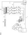
- Fig. 1 is a schematic diagram showing the overall configuration of seal affixing system 1
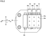
- Fig. 2 is a view showing a schematic configuration of a porous adsorption end effector 20 of seal affixing system 1
- Fig. 3 is a circuit diagram showing the overall configuration of seal affixing system 1.
- seal affixing system 1 includes a vertical articulated 6-axis robot arm 10, porous adsorption end effector 20, a compressed air generator 60, a controller 70, and a suction power generator 80.
- Porous adsorption end effector 20 is fixed to a porous adsorption end effector attachment part 10a of vertical articulated 6-axis robot arm 10.
- Porous adsorption end effector 20 has an adsorption face 20e including a plurality of adsorption pores 20h to which a seal S is to be adsorbed.
- Controller 70 controls suction power generator 80 in adsorbing seal S by porous adsorption end effector 20 and affixing seal S to an external target T.
- suction power generator 80 has a first vacuum line V1, a second vacuum line V2, and a third vacuum line V3.
- first vacuum line V1 a first vacuum ejector 30a, and a first pressure switch 40a are connected in this order to a first suction port 20a provided in porous adsorption end effector 20 by a first air piping L3a.
- second vacuum line V2 a second vacuum ejector 30b, and a second pressure switch 40b are connected in this order to a second suction port 20b provided in porous adsorption end effector 20 by a second air piping L3b.
- third vacuum line V3 a third vacuum ejector 30c, and a third pressure switch 40c are connected in this order to a third suction port 20c provided in porous adsorption end effector 20 by a third air piping L3c.
- First vacuum ejector 30a, second vacuum ejector 30b, and third vacuum ejector 30c form a vacuum pressure for seal adsorption in porous adsorption end effector 20 on the basis of fed compressed air.
- First pressure switch 40a, second pressure switch 40b, and third pressure switch 40c detect air pressure of the respective vacuum lines.
- First vacuum line V1, second vacuum line V2, and third vacuum line V3 are connected to a valve manifold 50.
- compressed air is introduced, for example, from compressed air generator 60 by an air piping L3.
- Valve manifold 50, first pressure switch 40a, second pressure switch 40b, and third pressure switch 40c are controlled by controller 70.
- controller 70 in the present disclosure includes a tool position controller configured to conduct a position control of porous adsorption end effector 20 for vertical articulated 6-axis robot arm 10. Positional information of porous adsorption end effector 20 may be obtained from a tool position controller that is separately provided.
- first direction X the direction along a movement direction X1 in which porous adsorption end effector 20 moves in affixing seal S to target T
- second direction Y the direction orthogonal to first direction X
- adsorption pores 20h are arranged plurally along first direction X and second direction Y on adsorption face 20e. Specifically, when first direction X is regarded as a row direction, and second direction Y is regarded as a column direction, a total of nine adsorption pores 20h are provided while they are aligned in 3 rows and 3 columns.
- adsorption pores 20h are sectioned into a plurality of suction regions including plurality of adsorption pores 20h from the upstream side to the downstream side along movement direction X1.
- sectioning is made along the column direction of second direction Y into a first suction region A1, a second suction region A2, and a third suction region A3.
- Three adsorption pores 20h located in the column direction belonging to first suction region A1 communicate with first suction port 20a.
- Three adsorption pores 20h located in the column direction belonging to second suction region A2 communicate with second suction port 20b.
- Three adsorption pores 20h located in the column direction belonging to third suction region A3 communicate with third suction port 20c.
- a seal holding roller 20r is provided on the upstream side of movement direction X1 in which porous adsorption end effector 20 moves.
- First vacuum line V1 communicates with first suction port 20a of porous adsorption end effector 20, and suction control of first suction region A1 is conducted.
- Supply of compressed air fed from compressed air generator 60 is controlled by controller 70 by a control line L1 (see Fig. 1 ), and distributed to first vacuum line V1 by valve manifold 50.
- Air pressure of first vacuum line V1 is detected by first pressure switch 40a, and monitored in controller 70 by a control line L2 (see Fig. 1 ).
- Second vacuum line V2 communicates with second suction port 20b of porous adsorption end effector 20, and suction control of second suction region A2 is conducted.
- Supply of compressed air fed from compressed air generator 60 is controlled by controller 70 by control line L1 (see Fig. 1 ), and distributed to second vacuum line V2 by valve manifold 50.
- Air pressure of second vacuum line V2 is detected by second pressure switch 40b, and monitored in controller 70 by control line L2 (see Fig. 1 ).
- Third vacuum line V3 communicates with third suction port 20c of porous adsorption end effector 20, and suction control of third suction region A3 is conducted.
- Supply of compressed air fed from compressed air generator 60 is controlled by controller 70 by control line L1 (see Fig. 1 ), and distributed to third vacuum line V3 by valve manifold 50.
- Air pressure of third vacuum line V3 is detected by third pressure switch 40c, and monitored in controller 70 by control line L2 (see Fig. 1 ).
- FIGs. 4 to 8 affixing steps of seal S by seal affixing system 1 having the above configuration is described.
- Figs. 4 to 7 are charts of the first to the fourth affixing steps of seal affixing system 1
- Fig. 8 shows a list of affixing steps of seal affixing system 1.
- adsorption pores 20h provided in porous adsorption end effector 20 are sectioned into first suction region A1, second suction region A2, and third suction region A3 from the downstream side (X1 side) to the upstream side (X2 side) along movement direction X1 of porous adsorption end effector 20.
- Controller 70 controls to individually suck these first suction region A1, second suction region A2, and third suction region A3.
- controller 70 conducts a control of sequentially stopping suction to first suction region A1, second suction region A2, or third suction region A3 for which adsorption of seal S to adsorption face 20e is determined to be unnecessary.
- controller 70 determines that adsorption of seal S to adsorption face 20e is unnecessary when the suction pressure does not reach a specified value. For example, when seal S that has been suctioned in first suction region A1 moves on adsorption face 20e with movement of porous adsorption end effector 20, and seal S comes off from first suction region A1, the suction pressure having been detected by first pressure switch 40a no longer reaches a specified value.
- controller 70 discriminates that the suction pressure having been detected by first pressure switch 40a does not reach a specified value, and stops distribution of compressed air to first vacuum line V1 by valve manifold 50 to end suction in first suction region A1. The same control is conducted also in second vacuum line V2 and third vacuum line V3.
- seal S is adsorbed in all regions including first suction region A1, second suction region A2, and third suction region A3 of adsorption face 20e, and compressed air is fed to first vacuum line V1, second vacuum line V2, and third vacuum line V3, and operation of each line is in ON state (affixing operation starts).
- porous adsorption end effector 20 moves a predetermined distance (D1) in movement direction X1, and the operation of affixing seal S to target T progresses. As a result, seal S comes off from first suction region A1. In this state, the suction pressure having been detected by first pressure switch 40a of first vacuum line V1 no longer reaches a specified value.
- controller 70 discriminates that the suction pressure having been detected by first pressure switch 40a does not reach a specified value, and stops distribution of compressed air to first vacuum line V1 by valve manifold 50 to end suction in first suction region A1.
- First vacuum line V1 is in OFF state, and second vacuum line V2 and third vacuum line V3 are in ON state (affixing by adsorption in first vacuum line V1 ends).
- porous adsorption end effector 20 further moves a predetermined distance (D2) in movement direction X1, and the operation of affixing seal S to target T progresses.
- D2 a predetermined distance
- seal S comes off from second suction region A2.
- the suction pressure having been detected by second pressure switch 40b of second vacuum line V2 no longer reaches a specified value.
- controller 70 discriminates that the suction pressure having been detected by second pressure switch 40b does not reach a specified value, and stops distribution of compressed air to second vacuum line V2 by valve manifold 50 to end suction of second suction region A2.
- First vacuum line V1 and second vacuum line V2 are in OFF state, and third vacuum line V3 is in ON state (affixing by adsorption in first vacuum line V1 and second vacuum line V2 ends).
- porous adsorption end effector 20 further moves a predetermined distance (D3) in movement direction X1, and the operation of affixing seal S to target T progresses.
- D3 a predetermined distance
- seal S comes off from third suction region A3.
- the suction pressure having been detected by third pressure switch 40c of third vacuum line V3 no longer reaches a specified value.
- controller 70 discriminates that the suction pressure having been detected by third pressure switch 40c does not reach a specified value, and stops distribution of compressed air to third vacuum line V3 by valve manifold 50 to end suction of third suction region A3.
- First vacuum line V1, second vacuum line V2, and third vacuum line V3 are in OFF state (affixing operation completes).
- the affixing step of seal S to target T using porous adsorption end effector 20 completes.
- seal affixing system 1 in the present disclosure suction operation of the suction region in which suction operation of seal S ends is stopped. As a result, adsorption power of seal S to adsorption face 20s does not change, so that adsorption power of seal S adsorbed by the remaining adsorption pores 20h will not deteriorate. This makes it possible to prevent generation of a turbulent spot such as a crease, an air bubble or the like in seal S at the time of affixing seal S to target T.
- porous adsorption end effector 20A of other embodiment is described. While porous adsorption end effector 20 of the above embodiment is described for the case where the suction region is divided into three regions: first suction region A1, second suction region A2, and third suction region A3, the number of suction regions is not limited to three, and as shown in Fig. 9 , the suction region may be divided into four regions: first suction region A1, second suction region A2, third suction region A3, and a fourth suction region A4, or may be divided into more regions.
- suction region is divided into four regions, and suction ports to be connected to respective regions, namely, first suction port 20a, second suction port 20b, third suction port 20c, and a fourth suction port 20d are provided.
- suction power generator 80 also has first vacuum line V1, second vacuum line V2, third vacuum line V3, and a fourth vacuum line V4.
- porous adsorption end effector 20A adsorption pores 20h arranged in each region are not aligned on the same straight line, but are arranged at random positions in each region.
- porous adsorption end effector 20A is employed, the same operation and effect as in seal affixing system 1 can be obtained.
- seal affixing system 1 in determination of unnecessity of adsorption of seal S to adsorption face 20e by controller 70, adsorption of seal S to adsorption face 20e is determined to be unnecessary when a suction pressure does not reach a specified value in adsorption control of each vacuum line, however, the following determining method may also be employed.
- controller 70 may check the progress of the operation of affixing seal S to target T on the basis of positional information of porous adsorption end effector 20 obtained from the tool position controller, and conduct a control of sequentially stopping suction to the vacuum line for which adsorption of seal S to adsorption face 20e is determined to be unnecessary.
- controller 70 ends the suction in first suction region A1 (affixing by adsorption in first vacuum line V1 ends). Further, on the basis of the positional information regarding movement of predetermined distance D2 in movement direction X1 of porous adsorption end effector 20, controller 70 ends the suction in second suction region A2 (affixing by adsorption in second vacuum line V2 ends).
- controller 70 ends the suction in third suction region A3 (affixing by adsorption in third vacuum line V3 ends).
- seal affixing system 1 The same operation and effect as aforementioned seal affixing system 1 can be obtained even in the case of employing the control of checking the progress of the operation of affixing seal S to target T on the basis of positional information of porous adsorption end effector 20 obtained from the seal position controller, and sequentially stopping suction to the vacuum line for which adsorption of seal S to adsorption face 20e is determined to be unnecessary.
- the present embodiment described above includes the following technical idea.
- seal affixing system of the present embodiment it becomes possible to affix a seal to a target without generation of a turbulent spot in the seal to be affixed.
Landscapes
- Engineering & Computer Science (AREA)
- Mechanical Engineering (AREA)
- Robotics (AREA)
- Chemical & Material Sciences (AREA)
- Dispersion Chemistry (AREA)
- Manipulator (AREA)
- Labeling Devices (AREA)
Abstract
Description
- The present technique relates to, for example, a seal affixing system configured to affix a seal to a target using a robot arm of the seal affixing system.
-
Japanese Patent Laying-Open No. 2017-133725 - In a seal affixing operation using a porous adsorption end effector provided in a seal affixing system, a seal is slid relatively to the target, on an adsorption face of the porous adsorption end effector while the seal is adsorbed. In this case, since the vacuum source of the seal adsorption pores of the porous adsorption mechanism is single, the area in which the adsorption pores are closed by the seal reduces as the seal affixing operation progresses, and air leakage occurs. As a result, the adsorption power of the seal adsorbed by the remaining adsorption pores deteriorates, and a turbulent spot such as a crease, an air bubble or the like can be generated in the affixed seal.
- The object of the present technique is to provide a seal affixing system capable of affixing a seal to a target without generation of a turbulent spot such as a crease, an air bubble or the like in the affixed seal.
- The seal affixing system according to the present technique includes a porous adsorption end effector having an adsorption face containing a plurality of adsorption pores to which a seal is to be adsorbed, a suction power generator configured to communicate with the adsorption pores and generate adsorption power of holding the seal by the adsorption face, and a controller configured to control the suction power generator in adsorbing the seal by the porous adsorption end effector and affixing the seal to an external target.
- When a direction along a movement direction in which the porous adsorption end effector moves in affixing the seal to the target is referred to as a first direction, and a direction orthogonal to the first direction is referred to as a second direction, the adsorption pores are arranged plurally along the first direction and the second direction on the adsorption face, the plurality of adsorption pores are sectioned into a plurality of suction regions containing a plurality of the adsorption pores from a downstream side to an upstream side along the movement direction, and the controller controls the suction power generator to individually suck the plurality of suction regions. According to this configuration, it is possible to affix a seal to a target without generation of a turbulent spot in the affixed seal.
- The controller conducts a control of sequentially stopping suction of the suction regions for which adsorption of the seal to the adsorption face is determined to be unnecessary as the operation of affixing the seal to the target progresses from a state where the seal is adsorbed in the plurality of suction regions. According to this configuration, it is possible to stop the suction of the suction region for which adsorption of the seal is unnecessary according to the operation of affixing the seal to the target. Suction power of the seal in the region where the seal is adsorbed will not deteriorate.
- The controller determines that adsorption of the seal to the adsorption face is unnecessary when the suction pressure does not reach a specified value. According to this configuration, it is possible to easily conduct discrimination of the suction region for which adsorption of the seal is unnecessary.
- A tool position controller configured to conduct a position control of the porous adsorption end effector is further provided, and the controller conducts a control of checking progress of an operation of affixing the seal to the target and sequentially stopping suction of the suction regions for which adsorption of the seal to the adsorption face is determined to be unnecessary on the basis of positional information of the porous adsorption end effector obtained from the tool position controller. According to this configuration, it is possible to easily conduct discrimination of the suction region for which adsorption of the seal is unnecessary.
- The foregoing and other objects, features, aspects and advantages of the present disclosure will become more apparent from the following detailed description of the present disclosure when taken in conjunction with the accompanying drawings.
-
-
Fig. 1 is a schematic diagram showing the overall configuration of a seal affixing system of the present embodiment. -
Fig. 2 is a view showing a schematic configuration of a porous adsorption end effector of the seal affixing system of the present embodiment. -
Fig. 3 is a circuit diagram showing the overall configuration of the seal affixing system of the present embodiment. -
Fig. 4 is a chart of a first seal affixing step by the seal affixing system of the present embodiment. -
Fig. 5 is a chart of a second seal affixing step by the seal affixing system of the present embodiment. -
Fig. 6 is a chart of a third seal affixing step by the seal affixing system of the present embodiment. -
Fig. 7 is a chart of a fourth seal affixing step by the seal affixing system of the present embodiment. -
Fig. 8 is a chart showing a list of affixing steps of the seal affixing system of the present embodiment. -
Fig. 9 is a view showing a schematic configuration of a porous adsorption end effector of a seal affixing system of the other embodiment. - Hereinafter, embodiments of the present technique are described. The same or corresponding part is denoted by the same reference numeral, and description thereof is not sometimes repeated.
- When a number, an amount and so on are referred in each embodiment described below, the scope of the present technique is not necessarily limited to the number, the amount and so on unless otherwise noted. In the following embodiments, each constituent is not necessarily essential for the present technique unless otherwise noted.
- In the present specification, descriptions of "comprise", "include" and "have" are open-ended. That is, when a certain constituent is included, a constituent other than the constituent may be included, and need not be included. The present technique is not necessarily limited to those exerting every operation and effect referred in the present embodiment.
- One example of the situation where the present technique is applied is described. In the present specification, description is made for a seal affixing system configured to affix a seal to a target using a robot arm of the seal affixing system as a typical example, however, the application is not limited to a seal affixing system configured to affix a seal to a target using a robot arm of the seal affixing system.
- Referring to
Figs. 1 to 3 , the outline of a seal affixing system 1 in the present embodiment is described.Fig. 1 is a schematic diagram showing the overall configuration of seal affixing system 1,Fig. 2 is a view showing a schematic configuration of a porousadsorption end effector 20 of seal affixing system 1, andFig. 3 is a circuit diagram showing the overall configuration of seal affixing system 1. - Referring to
Fig. 1 , seal affixing system 1 includes a vertical articulated 6-axis robot arm 10, porousadsorption end effector 20, acompressed air generator 60, acontroller 70, and asuction power generator 80. Porousadsorption end effector 20 is fixed to a porous adsorption endeffector attachment part 10a of vertical articulated 6-axis robot arm 10. - Vertical articulated 6-
axis robot arm 10 conducts a position control of porousadsorption end effector 20. Porousadsorption end effector 20 has anadsorption face 20e including a plurality ofadsorption pores 20h to which a seal S is to be adsorbed.Controller 70 controlssuction power generator 80 in adsorbing seal S by porousadsorption end effector 20 and affixing seal S to an external target T. - In the present disclosure,
suction power generator 80 has a first vacuum line V1, a second vacuum line V2, and a third vacuum line V3. - In first vacuum line V1, a first vacuum ejector 30a, and a
first pressure switch 40a are connected in this order to afirst suction port 20a provided in porousadsorption end effector 20 by a first air piping L3a. Similarly, in second vacuum line V2, asecond vacuum ejector 30b, and asecond pressure switch 40b are connected in this order to asecond suction port 20b provided in porousadsorption end effector 20 by a second air piping L3b. Similarly, in third vacuum line V3, athird vacuum ejector 30c, and athird pressure switch 40c are connected in this order to athird suction port 20c provided in porousadsorption end effector 20 by a third air piping L3c. - First vacuum ejector 30a,
second vacuum ejector 30b, andthird vacuum ejector 30c form a vacuum pressure for seal adsorption in porousadsorption end effector 20 on the basis of fed compressed air.First pressure switch 40a,second pressure switch 40b, andthird pressure switch 40c detect air pressure of the respective vacuum lines. - First vacuum line V1, second vacuum line V2, and third vacuum line V3 are connected to a
valve manifold 50. Intovalve manifold 50, compressed air is introduced, for example, fromcompressed air generator 60 by an air piping L3. - Valve
manifold 50,first pressure switch 40a,second pressure switch 40b, andthird pressure switch 40c are controlled bycontroller 70. Further,controller 70 in the present disclosure includes a tool position controller configured to conduct a position control of porousadsorption end effector 20 for vertical articulated 6-axis robot arm 10. Positional information of porousadsorption end effector 20 may be obtained from a tool position controller that is separately provided. - Referring to
Fig. 2 , arrangement of plurality ofadsorption pores 20h provided inadsorption face 20e of porousadsorption end effector 20, and relation of the vacuum lines are described. Here, the direction along a movement direction X1 in which porousadsorption end effector 20 moves in affixing seal S to target T (reverse direction is X2) is referred to as a first direction X, and the direction orthogonal to first direction X is referred to as a second direction Y. - In the present disclosure,
adsorption pores 20h are arranged plurally along first direction X and second direction Y onadsorption face 20e. Specifically, when first direction X is regarded as a row direction, and second direction Y is regarded as a column direction, a total of nineadsorption pores 20h are provided while they are aligned in 3 rows and 3 columns. - Further,
adsorption pores 20h are sectioned into a plurality of suction regions including plurality ofadsorption pores 20h from the upstream side to the downstream side along movement direction X1. - Specifically, sectioning is made along the column direction of second direction Y into a first suction region A1, a second suction region A2, and a third suction region A3. Three
adsorption pores 20h located in the column direction belonging to first suction region A1 communicate withfirst suction port 20a. Threeadsorption pores 20h located in the column direction belonging to second suction region A2 communicate withsecond suction port 20b. Threeadsorption pores 20h located in the column direction belonging to third suction region A3 communicate withthird suction port 20c. - On the upstream side of movement direction X1 in which porous
adsorption end effector 20 moves, aseal holding roller 20r is provided. - Referring to
Fig. 3 , adsorption control of each vacuum line is described. First vacuum line V1 communicates withfirst suction port 20a of porousadsorption end effector 20, and suction control of first suction region A1 is conducted. Supply of compressed air fed fromcompressed air generator 60 is controlled bycontroller 70 by a control line L1 (seeFig. 1 ), and distributed to first vacuum line V1 byvalve manifold 50. Air pressure of first vacuum line V1 is detected byfirst pressure switch 40a, and monitored incontroller 70 by a control line L2 (seeFig. 1 ). - Second vacuum line V2 communicates with
second suction port 20b of porousadsorption end effector 20, and suction control of second suction region A2 is conducted. Supply of compressed air fed fromcompressed air generator 60 is controlled bycontroller 70 by control line L1 (seeFig. 1 ), and distributed to second vacuum line V2 byvalve manifold 50. Air pressure of second vacuum line V2 is detected bysecond pressure switch 40b, and monitored incontroller 70 by control line L2 (seeFig. 1 ). - Third vacuum line V3 communicates with
third suction port 20c of porousadsorption end effector 20, and suction control of third suction region A3 is conducted. Supply of compressed air fed fromcompressed air generator 60 is controlled bycontroller 70 by control line L1 (seeFig. 1 ), and distributed to third vacuum line V3 byvalve manifold 50. Air pressure of third vacuum line V3 is detected bythird pressure switch 40c, and monitored incontroller 70 by control line L2 (seeFig. 1 ). - Next, referring to
Figs. 4 to 8 , affixing steps of seal S by seal affixing system 1 having the above configuration is described.Figs. 4 to 7 are charts of the first to the fourth affixing steps of seal affixing system 1, andFig. 8 shows a list of affixing steps of seal affixing system 1. - In seal affixing system 1,
adsorption pores 20h provided in porousadsorption end effector 20 are sectioned into first suction region A1, second suction region A2, and third suction region A3 from the downstream side (X1 side) to the upstream side (X2 side) along movement direction X1 of porousadsorption end effector 20.Controller 70 controls to individually suck these first suction region A1, second suction region A2, and third suction region A3. - As one example of the present disclosure, as the operation of affixing seal S to target T progresses from the state where seal S is adsorbed in first suction region A1, second suction region A2, and third suction region A3,
controller 70 conducts a control of sequentially stopping suction to first suction region A1, second suction region A2, or third suction region A3 for which adsorption of seal S to adsorptionface 20e is determined to be unnecessary. - Specifically,
controller 70 determines that adsorption of seal S to adsorptionface 20e is unnecessary when the suction pressure does not reach a specified value. For example, when seal S that has been suctioned in first suction region A1 moves onadsorption face 20e with movement of porousadsorption end effector 20, and seal S comes off from first suction region A1, the suction pressure having been detected byfirst pressure switch 40a no longer reaches a specified value. - Accordingly,
controller 70 discriminates that the suction pressure having been detected byfirst pressure switch 40a does not reach a specified value, and stops distribution of compressed air to first vacuum line V1 byvalve manifold 50 to end suction in first suction region A1. The same control is conducted also in second vacuum line V2 and third vacuum line V3. - On the basis of the above control, the first to fourth affixing steps of seal S to target T are described. First, referring to
Figs. 4 and8 , in the first affixing step, an operation of affixing seal S to target T by porousadsorption end effector 20 that is positioned at a predetermined position by vertical articulated 6-axis robot arm starts. - In this state, seal S is adsorbed in all regions including first suction region A1, second suction region A2, and third suction region A3 of
adsorption face 20e, and compressed air is fed to first vacuum line V1, second vacuum line V2, and third vacuum line V3, and operation of each line is in ON state (affixing operation starts). - Next, referring to
Figs. 5 and8 , in the second affixing step, porousadsorption end effector 20 moves a predetermined distance (D1) in movement direction X1, and the operation of affixing seal S to target T progresses. As a result, seal S comes off from first suction region A1. In this state, the suction pressure having been detected byfirst pressure switch 40a of first vacuum line V1 no longer reaches a specified value. - Accordingly,
controller 70 discriminates that the suction pressure having been detected byfirst pressure switch 40a does not reach a specified value, and stops distribution of compressed air to first vacuum line V1 byvalve manifold 50 to end suction in first suction region A1. First vacuum line V1 is in OFF state, and second vacuum line V2 and third vacuum line V3 are in ON state (affixing by adsorption in first vacuum line V1 ends). - Next, referring to
Figs. 6 and8 , in the third affixing step, porousadsorption end effector 20 further moves a predetermined distance (D2) in movement direction X1, and the operation of affixing seal S to target T progresses. As a result, seal S comes off from second suction region A2. In this state, the suction pressure having been detected bysecond pressure switch 40b of second vacuum line V2 no longer reaches a specified value. - Accordingly,
controller 70 discriminates that the suction pressure having been detected bysecond pressure switch 40b does not reach a specified value, and stops distribution of compressed air to second vacuum line V2 byvalve manifold 50 to end suction of second suction region A2. First vacuum line V1 and second vacuum line V2 are in OFF state, and third vacuum line V3 is in ON state (affixing by adsorption in first vacuum line V1 and second vacuum line V2 ends). - Next, referring to
Figs. 6 and8 , in the fourth affixing step, porousadsorption end effector 20 further moves a predetermined distance (D3) in movement direction X1, and the operation of affixing seal S to target T progresses. As a result, seal S comes off from third suction region A3. In this state, the suction pressure having been detected bythird pressure switch 40c of third vacuum line V3 no longer reaches a specified value. - Accordingly,
controller 70 discriminates that the suction pressure having been detected bythird pressure switch 40c does not reach a specified value, and stops distribution of compressed air to third vacuum line V3 byvalve manifold 50 to end suction of third suction region A3. First vacuum line V1, second vacuum line V2, and third vacuum line V3 are in OFF state (affixing operation completes). Thus, the affixing step of seal S to target T using porousadsorption end effector 20 completes. - As described above, according to seal affixing system 1 in the present disclosure, suction operation of the suction region in which suction operation of seal S ends is stopped. As a result, adsorption power of seal S to adsorption face 20s does not change, so that adsorption power of seal S adsorbed by the remaining
adsorption pores 20h will not deteriorate. This makes it possible to prevent generation of a turbulent spot such as a crease, an air bubble or the like in seal S at the time of affixing seal S to target T. - Referring to
Fig. 9 , a porousadsorption end effector 20A of other embodiment is described. While porousadsorption end effector 20 of the above embodiment is described for the case where the suction region is divided into three regions: first suction region A1, second suction region A2, and third suction region A3, the number of suction regions is not limited to three, and as shown inFig. 9 , the suction region may be divided into four regions: first suction region A1, second suction region A2, third suction region A3, and a fourth suction region A4, or may be divided into more regions. - In porous
adsorption end effector 20A, the suction region is divided into four regions, and suction ports to be connected to respective regions, namely,first suction port 20a,second suction port 20b,third suction port 20c, and a fourth suction port 20d are provided. Although omitted in the drawing,suction power generator 80 also has first vacuum line V1, second vacuum line V2, third vacuum line V3, and a fourth vacuum line V4. - Further, in porous
adsorption end effector 20A,adsorption pores 20h arranged in each region are not aligned on the same straight line, but are arranged at random positions in each region. - Also in the case where porous
adsorption end effector 20A is employed, the same operation and effect as in seal affixing system 1 can be obtained. - In seal affixing system 1, in determination of unnecessity of adsorption of seal S to adsorption
face 20e bycontroller 70, adsorption of seal S to adsorptionface 20e is determined to be unnecessary when a suction pressure does not reach a specified value in adsorption control of each vacuum line, however, the following determining method may also be employed. - Referring again to
Figs. 4 to 8 , in each affixing step of seal S, a control of further moving porousadsorption end effector 20 a predetermined distance in movement direction X1 is conducted. Since the control is conducted by the tool position controller configured to conduct a position control of porousadsorption end effector 20 for vertical articulated 6-axis robot arm,controller 70 may check the progress of the operation of affixing seal S to target T on the basis of positional information of porousadsorption end effector 20 obtained from the tool position controller, and conduct a control of sequentially stopping suction to the vacuum line for which adsorption of seal S to adsorptionface 20e is determined to be unnecessary. - Specifically, on the basis of the positional information regarding movement of predetermined distance D 1 in movement direction X1 of porous
adsorption end effector 20,controller 70 ends the suction in first suction region A1 (affixing by adsorption in first vacuum line V1 ends). Further, on the basis of the positional information regarding movement of predetermined distance D2 in movement direction X1 of porousadsorption end effector 20,controller 70 ends the suction in second suction region A2 (affixing by adsorption in second vacuum line V2 ends). Further, on the basis of the positional information regarding movement of predetermined distance D3 in movement direction X1 of porousadsorption end effector 20,controller 70 ends the suction in third suction region A3 (affixing by adsorption in third vacuum line V3 ends). - The same operation and effect as aforementioned seal affixing system 1 can be obtained even in the case of employing the control of checking the progress of the operation of affixing seal S to target T on the basis of positional information of porous
adsorption end effector 20 obtained from the seal position controller, and sequentially stopping suction to the vacuum line for which adsorption of seal S to adsorptionface 20e is determined to be unnecessary. - The present embodiment described above includes the following technical idea.
- [Configuration 1] A seal affixing system including:
- a porous adsorption end effector (20) having an adsorption face (20e) containing a plurality of adsorption pores (20h) to which seal (S) is to be adsorbed;
- a suction power generator (80) configured to communicate with the adsorption pores (20h) and generate adsorption power of holding the seal (S) by the adsorption face (20e); and
- a controller (70) configured to control the suction power generator (80) in adsorbing the seal (S) by the porous adsorption end effector (20) and affixing the seal (S) to an external target (T),
- wherein when a direction along a movement direction (X1) in which the porous adsorption end effector (20) moves in affixing the seal (S) to the target (T) is referred to as a first direction (X), and a direction orthogonal to the first direction (X) is referred to as a second direction (Y),
- the adsorption pores (20h) are arranged plurally along the first direction (X) and the second direction (Y) on the adsorption face (20e),
- the plurality of adsorption pores (20h) are sectioned into a plurality of suction regions (A1, A2, A3) containing a plurality of the adsorption pores (20h) from a downstream side to an upstream side along the movement direction (X1), and
- the controller (70) controls the suction power generator (80) to individually suck the plurality of suction regions (A1, A2, A3).
- [Configuration 2] The seal affixing system according to Configuration 1, wherein the controller (70)
- conducts a control of sequentially stopping suction of the suction regions (A1, A2, A3) for which adsorption of the seal (S) to the adsorption face (20e) is determined to be unnecessary as an operation of affixing the seal (S) to the target (T) progresses,
- from a state where the seal (S) is adsorbed in the plurality of suction regions (A1, A2, A3).
- [Configuration 3] The seal affixing system according to Configuration 2, wherein the controller (70) determines that adsorption of the seal (S) to the adsorption face (20e) is unnecessary when a suction pressure does not reach a specified value.
- [Configuration 4] The seal affixing system according to Configuration 2, further including:
- a tool position controller configured to conduct a position control of the porous adsorption end effector (20),
- wherein the controller (70) conducts a control of checking progress of an operation of affixing the seal (S) to the target (T) and sequentially stopping suction of the suction regions (A1, A2, A3) for which adsorption of the seal (S) to the adsorption face (20e) is determined to be unnecessary on the basis of positional information of the porous adsorption end effector (20) obtained from the tool position controller.
- According to the seal affixing system of the present embodiment, it becomes possible to affix a seal to a target without generation of a turbulent spot in the seal to be affixed.
- Although the present invention has been described and illustrated in detail, it is clearly understood that the same is by way of illustration and example only and is not to be taken by way of limitation, the scope of the present invention being interpreted by the terms of the appended claims.
Claims (4)
- A seal affixing system comprising:a porous adsorption end effector (20) having an adsorption face (20e) containing a plurality of adsorption pores (20h) to which seal (S) is to be adsorbed;a suction power generator (80) configured to communicate with the adsorption pores (20h) and generate adsorption power of holding the seal (S) by the adsorption face (20e); anda controller (70) configured to control the suction power generator (80) in adsorbing the seal (S) by the porous adsorption end effector (20) and affixing the seal (S) to an external target (T),wherein when a direction along a movement direction (X1) in which the porous adsorption end effector (20) moves in affixing the seal (S) to the target (T) is referred to as a first direction (X), and a direction orthogonal to the first direction (X) is referred to as a second direction (Y),the adsorption pores (20h) are arranged plurally along the first direction (X) and the second direction (Y) on the adsorption face (20e),the plurality of adsorption pores (20h) are sectioned into a plurality of suction regions (A1, A2, A3) containing a plurality of the adsorption pores (20h) from a downstream side to an upstream side along the movement direction (X1), andthe controller (70) controls the suction power generator (80) to individually suck the plurality of suction regions (A1, A2, A3).
- The seal affixing system according to claim 1, whereinthe controller (70)conducts a control of sequentially stopping suction of the suction regions (A1, A2, A3) for which adsorption of the seal (S) to the adsorption face (20e) is determined to be unnecessary as an operation of affixing the seal (S) to the target (T) progresses,from a state where the seal (S) is adsorbed in the plurality of suction regions (A1, A2, A3).
- The seal affixing system according to claim 2, wherein
the controller (70) determines that adsorption of the seal (S) to the adsorption face (20e) is unnecessary when a suction pressure does not reach a specified value. - The seal affixing system according to claim 2, further comprising a tool position controller configured to conduct a position control of the porous adsorption end effector (20),
wherein the controller (70) conducts a control of checking progress of the operation of affixing the seal (S) to the target (T) and sequentially stopping suction of the suction regions (A1, A2, A3) for which adsorption of the seal (S) to the adsorption face (20e) is determined to be unnecessary on the basis of positional information of the porous adsorption end effector (20) obtained from the tool position controller.
Applications Claiming Priority (1)
| Application Number | Priority Date | Filing Date | Title |
|---|---|---|---|
| JP2022035202A JP2023130738A (en) | 2022-03-08 | 2022-03-08 | Seal pasting system |
Publications (2)
| Publication Number | Publication Date |
|---|---|
| EP4241932A1 true EP4241932A1 (en) | 2023-09-13 |
| EP4241932B1 EP4241932B1 (en) | 2024-10-09 |
Family
ID=85238950
Family Applications (1)
| Application Number | Title | Priority Date | Filing Date |
|---|---|---|---|
| EP23156603.5A Active EP4241932B1 (en) | 2022-03-08 | 2023-02-14 | Seal affixing system |
Country Status (4)
| Country | Link |
|---|---|
| US (1) | US12202130B2 (en) |
| EP (1) | EP4241932B1 (en) |
| JP (1) | JP2023130738A (en) |
| CN (1) | CN116729758A (en) |
Families Citing this family (3)
| Publication number | Priority date | Publication date | Assignee | Title |
|---|---|---|---|---|
| JP1726803S (en) * | 2022-01-21 | 2022-10-06 | porous adsorber | |
| JP1724248S (en) * | 2022-01-21 | 2022-09-08 | Robot arm for sticker application system | |
| JP1722251S (en) * | 2022-01-21 | 2022-08-12 | seal feeder |
Citations (3)
| Publication number | Priority date | Publication date | Assignee | Title |
|---|---|---|---|---|
| US6336492B1 (en) * | 1998-10-30 | 2002-01-08 | Sony Chemicals Corporation | Mounting head apparatus and mounting method |
| US20130129464A1 (en) * | 2011-11-18 | 2013-05-23 | Nike, Inc. | Zoned activation manufacturing vacuum tool |
| JP2017133725A (en) | 2016-01-26 | 2017-08-03 | 三菱重工業株式会社 | Accumulator and compressor having a plurality of pipes |
Family Cites Families (9)
| Publication number | Priority date | Publication date | Assignee | Title |
|---|---|---|---|---|
| US20040102804A1 (en) * | 1999-08-10 | 2004-05-27 | Chin Albert K. | Apparatus and methods for endoscopic surgical procedures |
| JP4512230B2 (en) * | 2000-04-07 | 2010-07-28 | 株式会社サトー | Label adsorption device |
| JP3737942B2 (en) * | 2000-09-26 | 2006-01-25 | 三晴精機株式会社 | Single drum type thermal paste activated labeler and continuous label sticking method using the labeler |
| JP2003182712A (en) * | 2001-12-21 | 2003-07-03 | Hiraga Kikai Kogyo Kk | Adhesive tape application machine |
| US11278331B2 (en) * | 2006-02-07 | 2022-03-22 | P Tech Llc | Method and devices for intracorporeal bonding of implants with thermal energy |
| US11253296B2 (en) * | 2006-02-07 | 2022-02-22 | P Tech, Llc | Methods and devices for intracorporeal bonding of implants with thermal energy |
| DE102017119943A1 (en) * | 2017-08-30 | 2019-02-28 | Khs Gmbh | Device for labeling containers |
| US20200375388A1 (en) * | 2017-12-04 | 2020-12-03 | Aabak Thoughts Pty Ltd | Robotic Beverage Preparation System and Control Systems and Methods Therefor |
| JP2023106993A (en) * | 2022-01-21 | 2023-08-02 | オムロン株式会社 | porous suction tool |
-
2022
- 2022-03-08 JP JP2022035202A patent/JP2023130738A/en not_active Withdrawn
-
2023
- 2023-02-08 CN CN202310126309.4A patent/CN116729758A/en active Pending
- 2023-02-14 US US18/168,672 patent/US12202130B2/en active Active
- 2023-02-14 EP EP23156603.5A patent/EP4241932B1/en active Active
Patent Citations (3)
| Publication number | Priority date | Publication date | Assignee | Title |
|---|---|---|---|---|
| US6336492B1 (en) * | 1998-10-30 | 2002-01-08 | Sony Chemicals Corporation | Mounting head apparatus and mounting method |
| US20130129464A1 (en) * | 2011-11-18 | 2013-05-23 | Nike, Inc. | Zoned activation manufacturing vacuum tool |
| JP2017133725A (en) | 2016-01-26 | 2017-08-03 | 三菱重工業株式会社 | Accumulator and compressor having a plurality of pipes |
Also Published As
| Publication number | Publication date |
|---|---|
| US20230286175A1 (en) | 2023-09-14 |
| CN116729758A (en) | 2023-09-12 |
| JP2023130738A (en) | 2023-09-21 |
| EP4241932B1 (en) | 2024-10-09 |
| US12202130B2 (en) | 2025-01-21 |
Similar Documents
| Publication | Publication Date | Title |
|---|---|---|
| EP4241932B1 (en) | Seal affixing system | |
| US20060054774A1 (en) | High-performance non-contact support platforms | |
| GB2254675A (en) | Valve base plate | |
| EP1102311A3 (en) | Method of and apparatus for dynamic alignment of substrates | |
| JP2008173744A (en) | Transport position adjustment method of transport system | |
| US20190024813A1 (en) | Component mounter | |
| US20060248977A1 (en) | Supporting unit, and moving table device and linear-motion guiding device using the supporting unit | |
| KR20150072831A (en) | Air pressure distributor for fluid supply | |
| CN102754017B (en) | Vacuum forming apparatus and image display manufacturing facility including same | |
| US12564971B2 (en) | Air chuck having first and second solenoid valves | |
| TW202228229A (en) | Substrate processing apparatus | |
| US20170339515A1 (en) | Workpiece holding system | |
| GB2254909A (en) | Valve block | |
| JP4982292B2 (en) | Coating apparatus and coating method | |
| US12502790B2 (en) | Vacuum control unit | |
| EP4219325A1 (en) | Multi-hole absorption tool | |
| JP2025509345A5 (en) | ||
| WO2013051877A2 (en) | Vacuum processing apparatus having a means for preventing counter-pressure between chambers | |
| CN101140474A (en) | Pressure control system | |
| US12504088B2 (en) | Valve module, valve arrangement and method | |
| KR20030036001A (en) | Xy pointing control device and electronic component mounting apparatus | |
| US12615986B2 (en) | Substrate processing apparatus and substrate processing method | |
| US10683894B2 (en) | Air bearing with variable air delivery | |
| KR20140121313A (en) | leak gas automatic control system of Process gas purification device | |
| KR20160104548A (en) | Decompression drying apparatus and substrate processing system |
Legal Events
| Date | Code | Title | Description |
|---|---|---|---|
| PUAI | Public reference made under article 153(3) epc to a published international application that has entered the european phase |
Free format text: ORIGINAL CODE: 0009012 |
|
| STAA | Information on the status of an ep patent application or granted ep patent |
Free format text: STATUS: REQUEST FOR EXAMINATION WAS MADE |
|
| 17P | Request for examination filed |
Effective date: 20230214 |
|
| AK | Designated contracting states |
Kind code of ref document: A1 Designated state(s): AL AT BE BG CH CY CZ DE DK EE ES FI FR GB GR HR HU IE IS IT LI LT LU LV MC ME MK MT NL NO PL PT RO RS SE SI SK SM TR |
|
| GRAP | Despatch of communication of intention to grant a patent |
Free format text: ORIGINAL CODE: EPIDOSNIGR1 |
|
| STAA | Information on the status of an ep patent application or granted ep patent |
Free format text: STATUS: GRANT OF PATENT IS INTENDED |
|
| INTG | Intention to grant announced |
Effective date: 20240507 |
|
| GRAS | Grant fee paid |
Free format text: ORIGINAL CODE: EPIDOSNIGR3 |
|
| GRAA | (expected) grant |
Free format text: ORIGINAL CODE: 0009210 |
|
| STAA | Information on the status of an ep patent application or granted ep patent |
Free format text: STATUS: THE PATENT HAS BEEN GRANTED |
|
| P01 | Opt-out of the competence of the unified patent court (upc) registered |
Free format text: CASE NUMBER: APP_45802/2024 Effective date: 20240807 |
|
| AK | Designated contracting states |
Kind code of ref document: B1 Designated state(s): AL AT BE BG CH CY CZ DE DK EE ES FI FR GB GR HR HU IE IS IT LI LT LU LV MC ME MK MT NL NO PL PT RO RS SE SI SK SM TR |
|
| REG | Reference to a national code |
Ref country code: CH Ref legal event code: EP |
|
| REG | Reference to a national code |
Ref country code: DE Ref legal event code: R096 Ref document number: 602023000666 Country of ref document: DE |
|
| REG | Reference to a national code |
Ref country code: IE Ref legal event code: FG4D |
|
| REG | Reference to a national code |
Ref country code: LT Ref legal event code: MG9D |
|
| REG | Reference to a national code |
Ref country code: NL Ref legal event code: MP Effective date: 20241009 |
|
| REG | Reference to a national code |
Ref country code: AT Ref legal event code: MK05 Ref document number: 1730088 Country of ref document: AT Kind code of ref document: T Effective date: 20241009 |
|
| PG25 | Lapsed in a contracting state [announced via postgrant information from national office to epo] |
Ref country code: NL Free format text: LAPSE BECAUSE OF FAILURE TO SUBMIT A TRANSLATION OF THE DESCRIPTION OR TO PAY THE FEE WITHIN THE PRESCRIBED TIME-LIMIT Effective date: 20241009 |
|
| PG25 | Lapsed in a contracting state [announced via postgrant information from national office to epo] |
Ref country code: NL Free format text: LAPSE BECAUSE OF FAILURE TO SUBMIT A TRANSLATION OF THE DESCRIPTION OR TO PAY THE FEE WITHIN THE PRESCRIBED TIME-LIMIT Effective date: 20241009 |
|
| PG25 | Lapsed in a contracting state [announced via postgrant information from national office to epo] |
Ref country code: HR Free format text: LAPSE BECAUSE OF FAILURE TO SUBMIT A TRANSLATION OF THE DESCRIPTION OR TO PAY THE FEE WITHIN THE PRESCRIBED TIME-LIMIT Effective date: 20241009 Ref country code: IS Free format text: LAPSE BECAUSE OF FAILURE TO SUBMIT A TRANSLATION OF THE DESCRIPTION OR TO PAY THE FEE WITHIN THE PRESCRIBED TIME-LIMIT Effective date: 20250209 Ref country code: PT Free format text: LAPSE BECAUSE OF FAILURE TO SUBMIT A TRANSLATION OF THE DESCRIPTION OR TO PAY THE FEE WITHIN THE PRESCRIBED TIME-LIMIT Effective date: 20250210 |
|
| PG25 | Lapsed in a contracting state [announced via postgrant information from national office to epo] |
Ref country code: FI Free format text: LAPSE BECAUSE OF FAILURE TO SUBMIT A TRANSLATION OF THE DESCRIPTION OR TO PAY THE FEE WITHIN THE PRESCRIBED TIME-LIMIT Effective date: 20241009 |
|
| PG25 | Lapsed in a contracting state [announced via postgrant information from national office to epo] |
Ref country code: BG Free format text: LAPSE BECAUSE OF FAILURE TO SUBMIT A TRANSLATION OF THE DESCRIPTION OR TO PAY THE FEE WITHIN THE PRESCRIBED TIME-LIMIT Effective date: 20241009 |
|
| PG25 | Lapsed in a contracting state [announced via postgrant information from national office to epo] |
Ref country code: ES Free format text: LAPSE BECAUSE OF FAILURE TO SUBMIT A TRANSLATION OF THE DESCRIPTION OR TO PAY THE FEE WITHIN THE PRESCRIBED TIME-LIMIT Effective date: 20241009 |
|
| PG25 | Lapsed in a contracting state [announced via postgrant information from national office to epo] |
Ref country code: NO Free format text: LAPSE BECAUSE OF FAILURE TO SUBMIT A TRANSLATION OF THE DESCRIPTION OR TO PAY THE FEE WITHIN THE PRESCRIBED TIME-LIMIT Effective date: 20250109 |
|
| PG25 | Lapsed in a contracting state [announced via postgrant information from national office to epo] |
Ref country code: AT Free format text: LAPSE BECAUSE OF FAILURE TO SUBMIT A TRANSLATION OF THE DESCRIPTION OR TO PAY THE FEE WITHIN THE PRESCRIBED TIME-LIMIT Effective date: 20241009 Ref country code: LV Free format text: LAPSE BECAUSE OF FAILURE TO SUBMIT A TRANSLATION OF THE DESCRIPTION OR TO PAY THE FEE WITHIN THE PRESCRIBED TIME-LIMIT Effective date: 20241009 Ref country code: GR Free format text: LAPSE BECAUSE OF FAILURE TO SUBMIT A TRANSLATION OF THE DESCRIPTION OR TO PAY THE FEE WITHIN THE PRESCRIBED TIME-LIMIT Effective date: 20250110 |
|
| PG25 | Lapsed in a contracting state [announced via postgrant information from national office to epo] |
Ref country code: PL Free format text: LAPSE BECAUSE OF FAILURE TO SUBMIT A TRANSLATION OF THE DESCRIPTION OR TO PAY THE FEE WITHIN THE PRESCRIBED TIME-LIMIT Effective date: 20241009 |
|
| PG25 | Lapsed in a contracting state [announced via postgrant information from national office to epo] |
Ref country code: RS Free format text: LAPSE BECAUSE OF FAILURE TO SUBMIT A TRANSLATION OF THE DESCRIPTION OR TO PAY THE FEE WITHIN THE PRESCRIBED TIME-LIMIT Effective date: 20250109 |
|
| PG25 | Lapsed in a contracting state [announced via postgrant information from national office to epo] |
Ref country code: SM Free format text: LAPSE BECAUSE OF FAILURE TO SUBMIT A TRANSLATION OF THE DESCRIPTION OR TO PAY THE FEE WITHIN THE PRESCRIBED TIME-LIMIT Effective date: 20241009 |
|
| PG25 | Lapsed in a contracting state [announced via postgrant information from national office to epo] |
Ref country code: DK Free format text: LAPSE BECAUSE OF FAILURE TO SUBMIT A TRANSLATION OF THE DESCRIPTION OR TO PAY THE FEE WITHIN THE PRESCRIBED TIME-LIMIT Effective date: 20241009 |
|
| REG | Reference to a national code |
Ref country code: DE Ref legal event code: R097 Ref document number: 602023000666 Country of ref document: DE |
|
| PG25 | Lapsed in a contracting state [announced via postgrant information from national office to epo] |
Ref country code: EE Free format text: LAPSE BECAUSE OF FAILURE TO SUBMIT A TRANSLATION OF THE DESCRIPTION OR TO PAY THE FEE WITHIN THE PRESCRIBED TIME-LIMIT Effective date: 20241009 |
|
| PG25 | Lapsed in a contracting state [announced via postgrant information from national office to epo] |
Ref country code: RO Free format text: LAPSE BECAUSE OF FAILURE TO SUBMIT A TRANSLATION OF THE DESCRIPTION OR TO PAY THE FEE WITHIN THE PRESCRIBED TIME-LIMIT Effective date: 20241009 |
|
| PG25 | Lapsed in a contracting state [announced via postgrant information from national office to epo] |
Ref country code: SK Free format text: LAPSE BECAUSE OF FAILURE TO SUBMIT A TRANSLATION OF THE DESCRIPTION OR TO PAY THE FEE WITHIN THE PRESCRIBED TIME-LIMIT Effective date: 20241009 |
|
| PG25 | Lapsed in a contracting state [announced via postgrant information from national office to epo] |
Ref country code: CZ Free format text: LAPSE BECAUSE OF FAILURE TO SUBMIT A TRANSLATION OF THE DESCRIPTION OR TO PAY THE FEE WITHIN THE PRESCRIBED TIME-LIMIT Effective date: 20241009 |
|
| PG25 | Lapsed in a contracting state [announced via postgrant information from national office to epo] |
Ref country code: IT Free format text: LAPSE BECAUSE OF FAILURE TO SUBMIT A TRANSLATION OF THE DESCRIPTION OR TO PAY THE FEE WITHIN THE PRESCRIBED TIME-LIMIT Effective date: 20241009 |
|
| PLBE | No opposition filed within time limit |
Free format text: ORIGINAL CODE: 0009261 |
|
| STAA | Information on the status of an ep patent application or granted ep patent |
Free format text: STATUS: NO OPPOSITION FILED WITHIN TIME LIMIT |
|
| PG25 | Lapsed in a contracting state [announced via postgrant information from national office to epo] |
Ref country code: SE Free format text: LAPSE BECAUSE OF FAILURE TO SUBMIT A TRANSLATION OF THE DESCRIPTION OR TO PAY THE FEE WITHIN THE PRESCRIBED TIME-LIMIT Effective date: 20241009 |
|
| PG25 | Lapsed in a contracting state [announced via postgrant information from national office to epo] |
Ref country code: MC Free format text: LAPSE BECAUSE OF FAILURE TO SUBMIT A TRANSLATION OF THE DESCRIPTION OR TO PAY THE FEE WITHIN THE PRESCRIBED TIME-LIMIT Effective date: 20241009 |
|
| 26N | No opposition filed |
Effective date: 20250710 |
|
| PG25 | Lapsed in a contracting state [announced via postgrant information from national office to epo] |
Ref country code: LU Free format text: LAPSE BECAUSE OF NON-PAYMENT OF DUE FEES Effective date: 20250214 |
|
| REG | Reference to a national code |
Ref country code: BE Ref legal event code: MM Effective date: 20250228 |
|
| PG25 | Lapsed in a contracting state [announced via postgrant information from national office to epo] |
Ref country code: FR Free format text: LAPSE BECAUSE OF NON-PAYMENT OF DUE FEES Effective date: 20250228 |
|
| PG25 | Lapsed in a contracting state [announced via postgrant information from national office to epo] |
Ref country code: BE Free format text: LAPSE BECAUSE OF NON-PAYMENT OF DUE FEES Effective date: 20250228 |
|
| PG25 | Lapsed in a contracting state [announced via postgrant information from national office to epo] |
Ref country code: IE Free format text: LAPSE BECAUSE OF NON-PAYMENT OF DUE FEES Effective date: 20250214 |
|
| PGFP | Annual fee paid to national office [announced via postgrant information from national office to epo] |
Ref country code: DE Payment date: 20260217 Year of fee payment: 4 |
|
| PG25 | Lapsed in a contracting state [announced via postgrant information from national office to epo] |
Ref country code: CY Free format text: LAPSE BECAUSE OF FAILURE TO SUBMIT A TRANSLATION OF THE DESCRIPTION OR TO PAY THE FEE WITHIN THE PRESCRIBED TIME-LIMIT Effective date: 20241009 |
|
| PG25 | Lapsed in a contracting state [announced via postgrant information from national office to epo] |
Ref country code: LT Free format text: LAPSE BECAUSE OF FAILURE TO SUBMIT A TRANSLATION OF THE DESCRIPTION OR TO PAY THE FEE WITHIN THE PRESCRIBED TIME-LIMIT Effective date: 20241009 |
|
| PG25 | Lapsed in a contracting state [announced via postgrant information from national office to epo] |
Ref country code: TR Free format text: LAPSE BECAUSE OF FAILURE TO SUBMIT A TRANSLATION OF THE DESCRIPTION OR TO PAY THE FEE WITHIN THE PRESCRIBED TIME-LIMIT Effective date: 20241009 |