EP4241902A1 - Additive manufacturing method for producing a part - Google Patents
Additive manufacturing method for producing a part Download PDFInfo
- Publication number
- EP4241902A1 EP4241902A1 EP22161275.7A EP22161275A EP4241902A1 EP 4241902 A1 EP4241902 A1 EP 4241902A1 EP 22161275 A EP22161275 A EP 22161275A EP 4241902 A1 EP4241902 A1 EP 4241902A1
- Authority
- EP
- European Patent Office
- Prior art keywords
- clamping
- clamping element
- contour
- female
- male
- Prior art date
- Legal status (The legal status is an assumption and is not a legal conclusion. Google has not performed a legal analysis and makes no representation as to the accuracy of the status listed.)
- Pending
Links
- 238000004519 manufacturing process Methods 0.000 title claims abstract description 55
- 239000000654 additive Substances 0.000 title claims abstract description 38
- 230000000996 additive effect Effects 0.000 title claims abstract description 38
- 238000000034 method Methods 0.000 claims abstract description 30
- 238000012805 post-processing Methods 0.000 claims abstract description 23
- 238000003754 machining Methods 0.000 claims abstract description 15
- 230000000295 complement effect Effects 0.000 claims description 5
- 239000007787 solid Substances 0.000 claims description 4
- 238000007499 fusion processing Methods 0.000 claims description 3
- 239000007943 implant Substances 0.000 claims description 2
- 238000000926 separation method Methods 0.000 description 11
- 238000011960 computer-aided design Methods 0.000 description 8
- 239000000463 material Substances 0.000 description 7
- 230000008569 process Effects 0.000 description 6
- 230000008901 benefit Effects 0.000 description 5
- 238000005520 cutting process Methods 0.000 description 4
- 230000007246 mechanism Effects 0.000 description 4
- 238000000110 selective laser sintering Methods 0.000 description 3
- 230000004927 fusion Effects 0.000 description 2
- 239000000843 powder Substances 0.000 description 2
- 238000000149 argon plasma sintering Methods 0.000 description 1
- 230000008859 change Effects 0.000 description 1
- 238000005516 engineering process Methods 0.000 description 1
- 230000010354 integration Effects 0.000 description 1
- 230000001788 irregular Effects 0.000 description 1
- 239000002184 metal Substances 0.000 description 1
- 238000003801 milling Methods 0.000 description 1
- 239000002243 precursor Substances 0.000 description 1
- 238000007639 printing Methods 0.000 description 1
- 239000002994 raw material Substances 0.000 description 1
- 238000007669 thermal treatment Methods 0.000 description 1
- 238000010200 validation analysis Methods 0.000 description 1
- 230000000007 visual effect Effects 0.000 description 1
Images


Classifications
-
- B—PERFORMING OPERATIONS; TRANSPORTING
- B29—WORKING OF PLASTICS; WORKING OF SUBSTANCES IN A PLASTIC STATE IN GENERAL
- B29C—SHAPING OR JOINING OF PLASTICS; SHAPING OF MATERIAL IN A PLASTIC STATE, NOT OTHERWISE PROVIDED FOR; AFTER-TREATMENT OF THE SHAPED PRODUCTS, e.g. REPAIRING
- B29C64/00—Additive manufacturing, i.e. manufacturing of three-dimensional [3D] objects by additive deposition, additive agglomeration or additive layering, e.g. by 3D printing, stereolithography or selective laser sintering
- B29C64/30—Auxiliary operations or equipment
- B29C64/386—Data acquisition or data processing for additive manufacturing
- B29C64/393—Data acquisition or data processing for additive manufacturing for controlling or regulating additive manufacturing processes
-
- B—PERFORMING OPERATIONS; TRANSPORTING
- B22—CASTING; POWDER METALLURGY
- B22F—WORKING METALLIC POWDER; MANUFACTURE OF ARTICLES FROM METALLIC POWDER; MAKING METALLIC POWDER; APPARATUS OR DEVICES SPECIALLY ADAPTED FOR METALLIC POWDER
- B22F10/00—Additive manufacturing of workpieces or articles from metallic powder
- B22F10/20—Direct sintering or melting
- B22F10/28—Powder bed fusion, e.g. selective laser melting [SLM] or electron beam melting [EBM]
-
- B—PERFORMING OPERATIONS; TRANSPORTING
- B22—CASTING; POWDER METALLURGY
- B22F—WORKING METALLIC POWDER; MANUFACTURE OF ARTICLES FROM METALLIC POWDER; MAKING METALLIC POWDER; APPARATUS OR DEVICES SPECIALLY ADAPTED FOR METALLIC POWDER
- B22F10/00—Additive manufacturing of workpieces or articles from metallic powder
- B22F10/60—Treatment of workpieces or articles after build-up
- B22F10/66—Treatment of workpieces or articles after build-up by mechanical means
-
- B—PERFORMING OPERATIONS; TRANSPORTING
- B22—CASTING; POWDER METALLURGY
- B22F—WORKING METALLIC POWDER; MANUFACTURE OF ARTICLES FROM METALLIC POWDER; MAKING METALLIC POWDER; APPARATUS OR DEVICES SPECIALLY ADAPTED FOR METALLIC POWDER
- B22F12/00—Apparatus or devices specially adapted for additive manufacturing; Auxiliary means for additive manufacturing; Combinations of additive manufacturing apparatus or devices with other processing apparatus or devices
- B22F12/80—Plants, production lines or modules
- B22F12/88—Handling of additively manufactured products, e.g. by robots
-
- B—PERFORMING OPERATIONS; TRANSPORTING
- B22—CASTING; POWDER METALLURGY
- B22F—WORKING METALLIC POWDER; MANUFACTURE OF ARTICLES FROM METALLIC POWDER; MAKING METALLIC POWDER; APPARATUS OR DEVICES SPECIALLY ADAPTED FOR METALLIC POWDER
- B22F5/00—Manufacture of workpieces or articles from metallic powder characterised by the special shape of the product
- B22F5/003—Articles made for being fractured or separated into parts
-
- B—PERFORMING OPERATIONS; TRANSPORTING
- B25—HAND TOOLS; PORTABLE POWER-DRIVEN TOOLS; MANIPULATORS
- B25B—TOOLS OR BENCH DEVICES NOT OTHERWISE PROVIDED FOR, FOR FASTENING, CONNECTING, DISENGAGING OR HOLDING
- B25B1/00—Vices
- B25B1/24—Details, e.g. jaws of special shape, slideways
- B25B1/2405—Construction of the jaws
- B25B1/241—Construction of the jaws characterised by surface features or material
- B25B1/2415—Construction of the jaws characterised by surface features or material being composed of a plurality of parts adapting to the shape of the workpiece
- B25B1/2421—Construction of the jaws characterised by surface features or material being composed of a plurality of parts adapting to the shape of the workpiece the parts having a linear movement
-
- B—PERFORMING OPERATIONS; TRANSPORTING
- B29—WORKING OF PLASTICS; WORKING OF SUBSTANCES IN A PLASTIC STATE IN GENERAL
- B29C—SHAPING OR JOINING OF PLASTICS; SHAPING OF MATERIAL IN A PLASTIC STATE, NOT OTHERWISE PROVIDED FOR; AFTER-TREATMENT OF THE SHAPED PRODUCTS, e.g. REPAIRING
- B29C64/00—Additive manufacturing, i.e. manufacturing of three-dimensional [3D] objects by additive deposition, additive agglomeration or additive layering, e.g. by 3D printing, stereolithography or selective laser sintering
- B29C64/10—Processes of additive manufacturing
- B29C64/141—Processes of additive manufacturing using only solid materials
- B29C64/153—Processes of additive manufacturing using only solid materials using layers of powder being selectively joined, e.g. by selective laser sintering or melting
-
- B—PERFORMING OPERATIONS; TRANSPORTING
- B33—ADDITIVE MANUFACTURING TECHNOLOGY
- B33Y—ADDITIVE MANUFACTURING, i.e. MANUFACTURING OF THREE-DIMENSIONAL [3-D] OBJECTS BY ADDITIVE DEPOSITION, ADDITIVE AGGLOMERATION OR ADDITIVE LAYERING, e.g. BY 3-D PRINTING, STEREOLITHOGRAPHY OR SELECTIVE LASER SINTERING
- B33Y10/00—Processes of additive manufacturing
-
- B—PERFORMING OPERATIONS; TRANSPORTING
- B33—ADDITIVE MANUFACTURING TECHNOLOGY
- B33Y—ADDITIVE MANUFACTURING, i.e. MANUFACTURING OF THREE-DIMENSIONAL [3-D] OBJECTS BY ADDITIVE DEPOSITION, ADDITIVE AGGLOMERATION OR ADDITIVE LAYERING, e.g. BY 3-D PRINTING, STEREOLITHOGRAPHY OR SELECTIVE LASER SINTERING
- B33Y30/00—Apparatus for additive manufacturing; Details thereof or accessories therefor
-
- B—PERFORMING OPERATIONS; TRANSPORTING
- B33—ADDITIVE MANUFACTURING TECHNOLOGY
- B33Y—ADDITIVE MANUFACTURING, i.e. MANUFACTURING OF THREE-DIMENSIONAL [3-D] OBJECTS BY ADDITIVE DEPOSITION, ADDITIVE AGGLOMERATION OR ADDITIVE LAYERING, e.g. BY 3-D PRINTING, STEREOLITHOGRAPHY OR SELECTIVE LASER SINTERING
- B33Y40/00—Auxiliary operations or equipment, e.g. for material handling
- B33Y40/20—Post-treatment, e.g. curing, coating or polishing
-
- B—PERFORMING OPERATIONS; TRANSPORTING
- B33—ADDITIVE MANUFACTURING TECHNOLOGY
- B33Y—ADDITIVE MANUFACTURING, i.e. MANUFACTURING OF THREE-DIMENSIONAL [3-D] OBJECTS BY ADDITIVE DEPOSITION, ADDITIVE AGGLOMERATION OR ADDITIVE LAYERING, e.g. BY 3-D PRINTING, STEREOLITHOGRAPHY OR SELECTIVE LASER SINTERING
- B33Y50/00—Data acquisition or data processing for additive manufacturing
- B33Y50/02—Data acquisition or data processing for additive manufacturing for controlling or regulating additive manufacturing processes
-
- B—PERFORMING OPERATIONS; TRANSPORTING
- B33—ADDITIVE MANUFACTURING TECHNOLOGY
- B33Y—ADDITIVE MANUFACTURING, i.e. MANUFACTURING OF THREE-DIMENSIONAL [3-D] OBJECTS BY ADDITIVE DEPOSITION, ADDITIVE AGGLOMERATION OR ADDITIVE LAYERING, e.g. BY 3-D PRINTING, STEREOLITHOGRAPHY OR SELECTIVE LASER SINTERING
- B33Y80/00—Products made by additive manufacturing
-
- G—PHYSICS
- G06—COMPUTING; CALCULATING OR COUNTING
- G06F—ELECTRIC DIGITAL DATA PROCESSING
- G06F30/00—Computer-aided design [CAD]
- G06F30/10—Geometric CAD
-
- B—PERFORMING OPERATIONS; TRANSPORTING
- B22—CASTING; POWDER METALLURGY
- B22F—WORKING METALLIC POWDER; MANUFACTURE OF ARTICLES FROM METALLIC POWDER; MAKING METALLIC POWDER; APPARATUS OR DEVICES SPECIALLY ADAPTED FOR METALLIC POWDER
- B22F5/00—Manufacture of workpieces or articles from metallic powder characterised by the special shape of the product
- B22F2005/004—Article comprising helical form elements
-
- B—PERFORMING OPERATIONS; TRANSPORTING
- B22—CASTING; POWDER METALLURGY
- B22F—WORKING METALLIC POWDER; MANUFACTURE OF ARTICLES FROM METALLIC POWDER; MAKING METALLIC POWDER; APPARATUS OR DEVICES SPECIALLY ADAPTED FOR METALLIC POWDER
- B22F2999/00—Aspects linked to processes or compositions used in powder metallurgy
-
- G—PHYSICS
- G06—COMPUTING; CALCULATING OR COUNTING
- G06F—ELECTRIC DIGITAL DATA PROCESSING
- G06F2113/00—Details relating to the application field
- G06F2113/10—Additive manufacturing, e.g. 3D printing
-
- Y—GENERAL TAGGING OF NEW TECHNOLOGICAL DEVELOPMENTS; GENERAL TAGGING OF CROSS-SECTIONAL TECHNOLOGIES SPANNING OVER SEVERAL SECTIONS OF THE IPC; TECHNICAL SUBJECTS COVERED BY FORMER USPC CROSS-REFERENCE ART COLLECTIONS [XRACs] AND DIGESTS
- Y02—TECHNOLOGIES OR APPLICATIONS FOR MITIGATION OR ADAPTATION AGAINST CLIMATE CHANGE
- Y02P—CLIMATE CHANGE MITIGATION TECHNOLOGIES IN THE PRODUCTION OR PROCESSING OF GOODS
- Y02P10/00—Technologies related to metal processing
- Y02P10/25—Process efficiency
Definitions
- the present invention is related to a method for manufacturing a part by additive manufacturing process.
- Additive manufacturing process is a non-traditional machining process to form a part by powder without applying any machining tools.
- One of the additive manufacturing process is Power Bed Fusion like Direct Metal Laser Sintering (DMLS), Selective Laser Sintering (SLS), Direct Metal Printing (DMP) and Laser Powder Bed Fusion (LPBF).
- DMLS Direct Metal Laser Sintering
- SLS Selective Laser Sintering
- DMP Direct Metal Printing
- LPBF Laser Powder Bed Fusion
- the separated part must be mounted into the machine tool individually. Since the post-processing cannot be conducted on the build plate, the references of the parts are lost after the separation. Hence, a challenging task for post-processing is to accurately and fastly clamp the separated part in the machine tool.
- the part can have a very complex geometry.
- the part cannot be easily clamped in a standard clamping device normally equipped in the machine tool.
- the part must also be stably clamped in the machine tool to withstand the large force acted on the part during the post-processing, such as milling.
- special fixtures are often additionally required for clamping the part. This causes additional costs.
- the positioning inaccuracy of the part in the machine tool can be directly transferred into the final part, which has again a high impact on the rejection rate. Therefore, an accurate and fast clamp mechanism for clamping the part after the additive manufacturing in the machine tool for post-processing plays an essential role for the final quality of the part produced by additive manufacturing process.
- additional support elements are manufactured along with the part.
- Such additional support elements can be directly clamped in a standard clamping device.
- One example is a so-called bolt-in solution described in the publication of "design and validation of integrated clamping interfaces for post-processing and robotic handling in additive manufacturing" published in the international journal of advanced manufacturing technology 118, 3761-3787 (2022 ).
- This design shows a part with integrated bolt elements as clamping interface of the part.
- such design is applicable for three-jaw clamping system. It is not suitable for other clamping system, for example parallel-jaw clamping system.
- at least three additional support elements namely, the bolt elements are required. Since the support elements are not a part of the final part, thus the material needed for forming the support elements are wasted material. The more support elements are needed, the more material is wasted.
- US10656626 discloses a system for manufacturing a discrete object from an additively manufactured body of material including a precursor to a discrete object and at least a reference feature.
- the reference feature is applied to enable the additively manufactured body of material to be located at a manufacturing device.
- additional mechanism is required to hold the additively manufactured body of material at this position, because the reference feature is only used as a locating feature.
- a method for manufacturing a part by additive manufacturing process comprises providing computer-aided design (CAD) data defining the geometry of the part and providing CAD data defining the geometry of a first clamping element.
- the geometry of the first clamping element is determined in consideration of the geometry of a second clamping element.
- the first clamping element and the second clamping element are configured so that after the additive manufacturing process the first clamping element can be clamped into the second clamping element for holding the part in a desired position for post processing the part.
- the method further comprises generating machining data based on the CAD data defining the geometry of the part and the CAD data defining the geometry of the first clamping element and forming the part and the first clamping element by additive manufacturing process based on the machining data.
- the first clamping element has at least two parallel side surfaces and the second clamping element has two vice jaws positioned in parallel to each other along the longitudinal direction of the second clamping element.
- the two parallel side surfaces of the first clamping element are interacted with the vice jaws of the second clamping element.
- On at least one of the parallel side surfaces of the first clamping element a plurality of female clamping contours are provided for engaging with a plurality of male clamping contours provided on the vise jaw in the clamped state.
- the first clamping element is a cuboid to be optimally clamped between the two vice jaws of the second clamping element.
- the additive manufacturing process comprises a pre-process for preparing machining data.
- the CAD data defining the geometry of the part and the first clamping element are provided or generated.
- the CAD data describing a 3D-modell of the part and the first clamping element is divided into the slices to generate the machining data, which can be used to form the part and the first clamping element layer by layer.
- the CAD data required for the additive manufacturing process describes not only the final shape of the part but also the geometry of the clamping element.
- the additive manufacturing process is a fast process for producing parts having complex shape.
- post-processing is in general essential to obtain the final shape and optimize the quality feature.
- the post-processing is conducted on the individual part after separating it from the build plate and in a machine tool. This means, the separated part must be repositioned in the machine tool.
- Two problems must be solved to ensure the efficient post-processing.
- the first problem is the positioning of the part in the machine tool, because the positioning information of the part in the machine for additive manufacturing is lost after the separation.
- the second problem is how to stably hold the part having a non-regular shape in the machine tool. Normally, a work piece having a simple shape like rectangular or cylinder is mounted into the machine tool as raw material for machining.
- a clamping system for the post-processing Before generating the machining data for manufacturing the part, a clamping system for the post-processing can be selected.
- a center parallel vice jaw clamping system is applied, since this type of clamping system is widely used and provides a fast and reliable clamping.
- the second clamping element is therefore a center parallel vice jaw clamping element having two vice jaws for clamping an object therebetween.
- the first clamping element is integrated on the part such that it can be clamped between the vice jaws to hold the part formed thereon in a desired position.
- the first clamping element can be designed and produced to be able to precisely interact with the second clamping element.
- clamping contours are provided on the interacting surfaces of the first clamping element and the second clamping element. These clamping contours sever on one hand as a referencing element and on the other hand can improve the stability of the clamping.
- the plurality of female clamping contours are formed on the side surfaces of the first clamping element and a plurality of complementary-shaped male clamping contours are formed on the contacting surface of the vice jaw.
- the two side surfaces of the first clamping element come into contact with the contacting surfaces of the two vice jaws such that each female clamping contour interacts with one male clamping contour.
- any parts having any shapes can be formed on the top of the first clamping element by additive manufacturing process and can be easily mounted in the machine tool for post-processing.
- the female clamping contours are formed on the side surfaces, the normal of which is orthogonal to the build-on direction. This has the advantage that the clamping forces can be acted on only the first clamping element not on the part.
- the female clamping contour and the male clamping contour have a complementary shape to obtain a form-fitting in the clamped state. Therefore, each female clamping contour fits exactly one male clamping contour to ensure an accurate referencing and reliable clamping mechanism.
- the female clamping contour has a pyramid-shaped recess that tapers from a base to an apex or an edge.
- the female clamping contour is a con-shaped recess, a cubic recess, a cylindrical recess, a spherical recess, a hemispherical recess or a wedge-shaped recess. Additionally, the female clamping contour defines the references in a first direction and in a second direction. For example, if the build on direction is directed to the Z direction, the female clamping contour provides the references in the X direction and the Z direction. In this manner, an automatic referencing can be achieved along with the clamping.
- the pyramid-shaped recess has four sidewalls and an apex, which is oriented inwardly.
- the pyramid-shaped recess can be designed by applying different types of pyramid such as a regular pyramid having a regular polygon base. Additionally triangle pyramid is also applicable.
- the male clamping contour features a complementary shape of the female clamping contour
- the male clamping contour is a protruding element that tapers from a base to an apex or an edge.
- the male clamping contour has a shape of pyramid, cone, cubic, a cylinder, sphere, hemisphere, or wedge.
- the apex of the pyramid-shaped male clamping contours is oriented outwardly to provide an abutment against the female clamping contour in the clamped state.
- the female clamping contour and the male clamping contour can also be designed vice versa.
- the female clamping contour is a protruding element and the male clamping contour is a recess.
- the parallel center clamping system is chosen because the parallel vise jaws can provide high clamping forces for variable spans. Besides, such clamping system is versatile and can be utilized for clamping a large variety of parts with various machine systems. It is almost available in all shop floors.
- the parallel center clamping system is also compatible with palletizing and automations systems.
- the second clamping system can be mounted on a pallet, which can be automatically loaded into the machine tool or dismounted from the machine tool by an automatic tool changer.
- the vise jaws are provided on the second clamping element for clamping the first clamping element therebetween and for holding the part during the post-processing.
- Each clamping jaw has a base body and a contacting surface arranged on the upper part of the base body.
- the plurality of male clamping contours are formed on the contacting surface to generate an abutment against the female clamping contours.
- the female clamping contour and male clamping contour are designed to fulfill two functions: precise positioning and reliable clamping.
- the female clamping contour has a pyramid-shaped recess and the male clamping contour is a protruding element having a pyramid shape
- the references in the two directions for example in X direction and Z direction are defined by this shape.
- the male clamping contour can be reliably received in the female clamping contour to ensure the clamping.
- the male clamping contour can be reliably accommodated in the female clamping contour in order to optimally ensure clamping even with high cutting forces in all directions during the post-processing.
- the size of the first clamping element can vary.
- the number of the female clamping contours provided on the first element can also simply changed during the design phase.
- the plurality of female clamping contours are provided along the horizontal direction, e.g. in X direction with equal distances to each other.
- the female clamping contours can also be provided on an irregular base with non-equal distances. It is further considerable to provide more than one first clamping element for one part.
- the first clamping elements are connected together through the part with a distance apart to each other.
- at least one female clamping contour is formed. In the clamped state, all first clamping elements are engaged with one second clamping element.
- the pyramid-shape provides also the advantage in view of production tolerances with high clamping force to avoid deforming the part by additional machining forces and stable clamping. Therefore, no change in position by additional forces generated during the post-processing can be raised. Moreover, pyramid provides a large clamping area. Thus, achieve a high clamping fore.
- the female clamping contours are provided on the low part of the first clamping element but apart from the bottom surface with a defined distance. This can make the separation easier because the female clamping contours cannot be cut by the cutting tools during separation. Additionally, as the bottom surface of the first clamping element does not come into contact with the second clamping element, the surface quality of the bottom surface is irrelevant and therefor can be low.
- the length of a vise jaw can vary for example in the range of 50 mm to 220 mm
- the first clamping element can engage with the second clamping element at any position along the whole length.
- the length of the first clamping element is smaller than the length of the second clamping element, namely the length of the vise jaw.
- a marking is provided to provide a reference on a third direction, namely in Y direction.
- a first marking is provided on the first clamping element and a second marking is provided on the second clamping element for referencing in the third direction, in particular, the marking defines the zero-point in Y direction.
- the first marking and/or the second marking is a visual marking such as a color or a pattern.
- the first clamping element is a solid element to obtain stable clamping.
- the first clamping element After the completion of the post-processing, the first clamping element must be removed from the part. Hence, a separating portion is formed between the first clamping element and the part by additive manufacturing process.
- the second clamping element can also be manufactured by the additive manufacturing process.
- the first clamping element is first formed and the part is formed on the top of the first clamping element along the build-on direction.
- the first clamping element can be designed to have a simple shape, such as cuboid or cubic.
- the requirement for separation can be low, because the cutting surface does not provide any function after the separation. It can neither has any negative influences on the final quality of the part and nor reduces the clamping stability.
- the part can be simply build on the top of the first clamping element and has a large freedom in view
- the method is suitable but not limited for producing the part having a substantial squared or solid shape, which can be stably formed on the top of the first clamping element.
- Such part is in particular a medical-technical implants and instruments, stamps and inserts for tool and mold making, such as a spinal cage.
- the part can be small to medium-sized structural parts for the automotive or aircraft industry.
- the size of the part can also vary.
- the cross-section of the part can be in the range of 10mm 2 to 500 mm 2 .
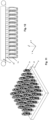
- Figures 1, 2 and 3 illustrate three different parts, each of which is manufactured together with a first clamping element by the method according to present invention.
- the part and the first clamping element are an integrated device and manufactured by additive manufacturing process in one run. Normally, a large number of parts are formed on one build plate 8 in parallel.
- the method of the present invention includes forming the first clamping element directly on the build plate first and forming the part on the top of the first clamping element in the build-on direction, namely in the Z-direction.
- each part together with the first clamping element is separated from the build plate as illustrated in figure 12 such that the individual part can be further processed to achieve the final shape and to optimize the surface quality.
- the post-processing is conducted at outside of the machine for additive manufacturing process and in a machine tool, thus, the individual part must be stably held in the machine tool for post-processing in a desired position.
- Direct integration of the clamping element on the part ease the clamping of the part in the machine tool and provides the advantage of a precise positioning and automatic referencing.
- Figures 1, 2 and 3 show the examples of the parts having different shapes and the first clamping elements with different designs.
- the first clamping element 10, 10a, 10b is a solid element and has a substantially cuboid shape with four side surfaces.
- a plurality of female clamping contours 20, 20a, 20b are embedded on at least one side surface of the first clamping element.
- the figure 1 shows one example of the first clamping element 10, which features on all side surfaces female clamping contours.
- the first clamping element 10 has a cubic shape.
- the female clamping contours 20 are arranged in parallel to each other and apart from the bottom surface of the first clamping element with a defined distance.
- the configuration of the female clamping contour on the second side surface 12 is the same as on the first side surface 11. However, it is not limited to such design.
- the shape, the positon, the dimension, and the number of the female clamping contours on different side surfaces can differ, but preferably be identical on the two parallel side surfaces, which come into contact with the second clamping element.
- Figure 2 shows another example of the first clamping element 10a that features the female clamping contours 20a on two parallel side surfaces.
- the female clamping contours are also arranged apart from the bottom of the first clamping element.
- the side surface in parallel to the first side surface 11a is on the backside of the first clamping element and thus not shown entirely in figure 2 .
- the second side surface 12a which is orthogonal to the first side surface 11a, no female clamping contour is provided.
- a separation region 15 is formed on the top of the female clamping contour and below the part 1a.
- Figure 3 shows an additional example of the first clamping element 10b having female clamping contours 20b on one side surface 11b. It can be taken from the figures 1, 2 and 3 that the shape of the first clamping element can vary in the length, width and the height.
- Figure 4 shows the first clamping element and a second clamping element in a clamped state, in which the first clamping element is clamped between two vise jaws 31, 32 of the second clamping element 30. Each vise jaw is interacted with one side surface of the first clamping element.
- a plurality of male clamping contours 40 are provided on the first contacting surface 33 of the vise jaw and on the second contacting surface 34 of the vise jaw.
- the shape of the male clamping contour is complementary to the shape of the female clamping contour of the first clamping element such that each male clamping contour can be precisely and stably received in one female clamping contour to obtain a stable clamping and obtain a self-referencing in the X and Z direction.
- Figures 4a and 4b depict the enlarged views of the male clamping contours 40 and the female clamping contours 20.
- the female clamping contour 20 is formed as a pyramid-shaped recess by four sidewalls. The apex of the pyramid defined by the common point of the four sidewalls projects inwardly.
- Two sidewalls 21 22 are configured in a way that they are shared by two neighboring female clamping contours. These sidewalls are defined as neighboring side walls.
- the neighboring sidewall with the reference numeral 21 is shared between the female clamping contours with the reference numerals 20 and 20a.
- the neighboring side wall with the reference numeral 22 is shared between the female clamping contours with the reference numerals 20 and 20b.
- the male clamping contour 40 features a complementary shape of the female clamping contour having the same pyramid shape.
- the male clamping contour has a base arranged on the side surface of the vise jaw and four lateral surfaces 41 42 43 44 and the apex 45 protruding outwardly. Between two male clamping contours a channel 47, 48 is formed on the contacting surface of the vise jaw. Each channel is shared by two male clamping contours such that the neighboring walls of the female clamping contour can be received in the channel to achieve a stable clamping. In the clamping state, the four lateral surfaces of the male clamping contour abut on the inner surface of the four sidewalls of the female clamping contours. The channels are provided to ensure the contact of the two element despite the production tolerance.
- the sidewalls 21, 22 of the female clamping contours are received in the channels 48 of the male clamping contours.
- the channels serve as an exemption such that the lateral surfaces of the male clamping contours can be pressed on the inner surface of the sidewalls of the female clamping contour to achieve the stable clamping. It is advantageous to design the male clamping contours having rounded edge to avoid the edge contact, because surface clamping can provide higher clamping forces than the edge contact.
- the second clamping element is provided with a first slot 35 and a second slot 36. They are located on the first contacting surface 33 and the second contact surface 34 of the vise jaws below the male clamping contours, respectively.
- the both slots sever also as an exemption such that the lateral surfaces of the male clamping element can direct interact with the female clamping contour to guarantee a surface clamping. In this manner, the part can be optimally clamped in the machine tool.
- a marking 37 is provided on the top surface of the vise jaw to indicate the zero-point.
- the first clamping element is not limited to be one single element but can comprises several clamping sections 16 as shown in figures 5 and 6 . At least one clamping section of the first clamping element comprises a plurality of female clamping contours 20b.
- the clamping sections are arranged in parallel to each other along the longitudinal directions, such as in Y-direction. All clamping sections are formed first and the part 1d is formed on the top of all clamping sections by the additive manufacturing process, thus, the clamping sections are connected indirectly through the part formed thereon.
- Figures 7a and 7b present another example of the male clamping contour, which has a con-shaped protrusion 20b. Accordingly, the female clamping contour, which is not shown in the figures 7a and 7b has a con-shaped recess to be engaged with the male clamping contour.
- Figures 8, 9 and 10 illustrate three examples of the part 1a, 1b and 1c manufactured by the method of the present invention.
Landscapes
- Engineering & Computer Science (AREA)
- Chemical & Material Sciences (AREA)
- Materials Engineering (AREA)
- Manufacturing & Machinery (AREA)
- Physics & Mathematics (AREA)
- Mechanical Engineering (AREA)
- Optics & Photonics (AREA)
- General Physics & Mathematics (AREA)
- Geometry (AREA)
- Theoretical Computer Science (AREA)
- Plasma & Fusion (AREA)
- Pure & Applied Mathematics (AREA)
- Mathematical Analysis (AREA)
- Mathematical Optimization (AREA)
- Computer Hardware Design (AREA)
- Evolutionary Computation (AREA)
- General Engineering & Computer Science (AREA)
- Computational Mathematics (AREA)
- Robotics (AREA)
- Jigs For Machine Tools (AREA)
- Powder Metallurgy (AREA)
Abstract
a. providing CAD data defining the geometry of the part;
b. providing CAD data defining the geometry of a first clamping element, wherein the geometry of the first clamping element is determined in consideration of the geometry of a second clamping element such that after the additive manufacturing process the first clamping element can be clamped into the second clamping element for holding the part in a desired position for post-processing;
c. generating machining data based on the CAD data defining the geometry of the part and the CAD data defining the geometry of the first clamping element;
d. forming the part and the first clamping element by additive manufacturing process based on the machining data.
Description
- The present invention is related to a method for manufacturing a part by additive manufacturing process.
- Additive manufacturing process is a non-traditional machining process to form a part by powder without applying any machining tools. One of the additive manufacturing process is Power Bed Fusion like Direct Metal Laser Sintering (DMLS), Selective Laser Sintering (SLS), Direct Metal Printing (DMP) and Laser Powder Bed Fusion (LPBF). This process enables to produce complex parts with low costs, because the cost mainly depends on the volume of the part to be built not on the complexity of its geometry. The short production time is another benefit from this process. Compared to the traditional machining process, such additive process does not require additional machining tools, which can also be expensive and extend the time to start the production. For these reasons, the additive manufacturing process is an attractive process in view of cost and production time.
- However, there are several drawbacks using such process. The parts produced by additive manufacturing process must be further processed for several reasons. One reason is that the thermal treatment is needed for certain material. Another reason is that many parts are normally formed on a build plate mounted in the machine for additive manufacturing and must be separated from the build plate after the additive manufacturing process. In addition, post-processing of individual parts are quite often required to complete the final shape of the part. For example, additive manufacturing process cannot form screw thread with tight tolerances, which exists in many parts. Moreover, sometimes the surface quality of the part must be improved, in particular, when the surface of the manufactured part must be connected with other elements, a good surface quality is essential for ensuring the connection. In the industry applications, the post-processing is usually accomplished by a machine tool. Thus, the separated part must be mounted into the machine tool individually. Since the post-processing cannot be conducted on the build plate, the references of the parts are lost after the separation. Hence, a challenging task for post-processing is to accurately and fastly clamp the separated part in the machine tool.
- In general, the part can have a very complex geometry. Thus, the part cannot be easily clamped in a standard clamping device normally equipped in the machine tool. The part must also be stably clamped in the machine tool to withstand the large force acted on the part during the post-processing, such as milling. For this reason, special fixtures are often additionally required for clamping the part. This causes additional costs. Moreover, the positioning inaccuracy of the part in the machine tool can be directly transferred into the final part, which has again a high impact on the rejection rate. Therefore, an accurate and fast clamp mechanism for clamping the part after the additive manufacturing in the machine tool for post-processing plays an essential role for the final quality of the part produced by additive manufacturing process.
- In order to overcome the drawbacks of the required post-processing steps for additively manufactured parts, additional support elements are manufactured along with the part. Such additional support elements can be directly clamped in a standard clamping device. One example is a so-called bolt-in solution described in the publication of "design and validation of integrated clamping interfaces for post-processing and robotic handling in additive manufacturing" published in the international journal of advanced manufacturing technology 118, 3761-3787 (2022). This design shows a part with integrated bolt elements as clamping interface of the part. However, such design is applicable for three-jaw clamping system. It is not suitable for other clamping system, for example parallel-jaw clamping system. Besides this drawback, at least three additional support elements namely, the bolt elements are required. Since the support elements are not a part of the final part, thus the material needed for forming the support elements are wasted material. The more support elements are needed, the more material is wasted.
-
US10656626 - It is an objective of this invention to provide a method for manufacturing a part by additive manufacturing process with an improved production efficiency and increased quality. In particular, it is an objective to provide a method for manufacturing a part by additive manufacturing process with an improved clamping mechanism for post-processing.
- In the present invention, a method for manufacturing a part by additive manufacturing process comprises providing computer-aided design (CAD) data defining the geometry of the part and providing CAD data defining the geometry of a first clamping element. The geometry of the first clamping element is determined in consideration of the geometry of a second clamping element. In further, the first clamping element and the second clamping element are configured so that after the additive manufacturing process the first clamping element can be clamped into the second clamping element for holding the part in a desired position for post processing the part. The method further comprises generating machining data based on the CAD data defining the geometry of the part and the CAD data defining the geometry of the first clamping element and forming the part and the first clamping element by additive manufacturing process based on the machining data. The first clamping element has at least two parallel side surfaces and the second clamping element has two vice jaws positioned in parallel to each other along the longitudinal direction of the second clamping element. In the clamped state, the two parallel side surfaces of the first clamping element are interacted with the vice jaws of the second clamping element. On at least one of the parallel side surfaces of the first clamping element a plurality of female clamping contours are provided for engaging with a plurality of male clamping contours provided on the vise jaw in the clamped state. Advantageously, the first clamping element is a cuboid to be optimally clamped between the two vice jaws of the second clamping element.
- The additive manufacturing process comprises a pre-process for preparing machining data. The CAD data defining the geometry of the part and the first clamping element are provided or generated. The CAD data describing a 3D-modell of the part and the first clamping element is divided into the slices to generate the machining data, which can be used to form the part and the first clamping element layer by layer. Thus, the CAD data required for the additive manufacturing process describes not only the final shape of the part but also the geometry of the clamping element.
- The additive manufacturing process is a fast process for producing parts having complex shape. However, post-processing is in general essential to obtain the final shape and optimize the quality feature. In further, the post-processing is conducted on the individual part after separating it from the build plate and in a machine tool. This means, the separated part must be repositioned in the machine tool. Two problems must be solved to ensure the efficient post-processing. The first problem is the positioning of the part in the machine tool, because the positioning information of the part in the machine for additive manufacturing is lost after the separation. The second problem is how to stably hold the part having a non-regular shape in the machine tool. Normally, a work piece having a simple shape like rectangular or cylinder is mounted into the machine tool as raw material for machining. In the present invention, these problems have been considered during the design phase of the part. Before generating the machining data for manufacturing the part, a clamping system for the post-processing can be selected. In the present invention, a center parallel vice jaw clamping system is applied, since this type of clamping system is widely used and provides a fast and reliable clamping. The second clamping element is therefore a center parallel vice jaw clamping element having two vice jaws for clamping an object therebetween. In order to avoid to directly clamp the part between the vice jaws, the first clamping element is integrated on the part such that it can be clamped between the vice jaws to hold the part formed thereon in a desired position. Since the geometry of the first clamping element is determined in consideration of the second clamping element, the first clamping element can be designed and produced to be able to precisely interact with the second clamping element. To achieve this, clamping contours are provided on the interacting surfaces of the first clamping element and the second clamping element. These clamping contours sever on one hand as a referencing element and on the other hand can improve the stability of the clamping. The plurality of female clamping contours are formed on the side surfaces of the first clamping element and a plurality of complementary-shaped male clamping contours are formed on the contacting surface of the vice jaw. In the clamped state, the two side surfaces of the first clamping element come into contact with the contacting surfaces of the two vice jaws such that each female clamping contour interacts with one male clamping contour. By this way, any parts having any shapes can be formed on the top of the first clamping element by additive manufacturing process and can be easily mounted in the machine tool for post-processing. The female clamping contours are formed on the side surfaces, the normal of which is orthogonal to the build-on direction. This has the advantage that the clamping forces can be acted on only the first clamping element not on the part.
- In some embodiments, the female clamping contour and the male clamping contour have a complementary shape to obtain a form-fitting in the clamped state. Therefore, each female clamping contour fits exactly one male clamping contour to ensure an accurate referencing and reliable clamping mechanism.
- Preferably, the female clamping contour has a pyramid-shaped recess that tapers from a base to an apex or an edge.
- The female clamping contour is a con-shaped recess, a cubic recess, a cylindrical recess, a spherical recess, a hemispherical recess or a wedge-shaped recess. Additionally, the female clamping contour defines the references in a first direction and in a second direction. For example, if the build on direction is directed to the Z direction, the female clamping contour provides the references in the X direction and the Z direction. In this manner, an automatic referencing can be achieved along with the clamping.
- In an advantageous variant, the pyramid-shaped recess has four sidewalls and an apex, which is oriented inwardly. The pyramid-shaped recess can be designed by applying different types of pyramid such as a regular pyramid having a regular polygon base. Additionally triangle pyramid is also applicable.
- As the male clamping contour features a complementary shape of the female clamping contour, the male clamping contour is a protruding element that tapers from a base to an apex or an edge.
- The male clamping contour has a shape of pyramid, cone, cubic, a cylinder, sphere, hemisphere, or wedge. In particular, the apex of the pyramid-shaped male clamping contours is oriented outwardly to provide an abutment against the female clamping contour in the clamped state.
- However, the female clamping contour and the male clamping contour can also be designed vice versa. In this variant, the female clamping contour is a protruding element and the male clamping contour is a recess.
- In the present invention, the parallel center clamping system is chosen because the parallel vise jaws can provide high clamping forces for variable spans. Besides, such clamping system is versatile and can be utilized for clamping a large variety of parts with various machine systems. It is almost available in all shop floors. The parallel center clamping system is also compatible with palletizing and automations systems. For example, the second clamping system can be mounted on a pallet, which can be automatically loaded into the machine tool or dismounted from the machine tool by an automatic tool changer.
- The vise jaws are provided on the second clamping element for clamping the first clamping element therebetween and for holding the part during the post-processing. Each clamping jaw has a base body and a contacting surface arranged on the upper part of the base body. The plurality of male clamping contours are formed on the contacting surface to generate an abutment against the female clamping contours.
- The female clamping contour and male clamping contour are designed to fulfill two functions: precise positioning and reliable clamping.
- When the female clamping contour has a pyramid-shaped recess and the male clamping contour is a protruding element having a pyramid shape, the references in the two directions for example in X direction and Z direction are defined by this shape. As a result, by clamping, the position of the part in X and Z direction can be precisely controlled. In further, the male clamping contour can be reliably received in the female clamping contour to ensure the clamping. Furthermore, the male clamping contour can be reliably accommodated in the female clamping contour in order to optimally ensure clamping even with high cutting forces in all directions during the post-processing.
- Depending on the dimensions of the part, the size of the first clamping element can vary. In further, the number of the female clamping contours provided on the first element can also simply changed during the design phase. In a preferred variant, the plurality of female clamping contours are provided along the horizontal direction, e.g. in X direction with equal distances to each other. However, in certain cases the female clamping contours can also be provided on an irregular base with non-equal distances. It is further considerable to provide more than one first clamping element for one part. The first clamping elements are connected together through the part with a distance apart to each other. Preferably, on each first clamping element at least one female clamping contour is formed. In the clamped state, all first clamping elements are engaged with one second clamping element.
- The pyramid-shape provides also the advantage in view of production tolerances with high clamping force to avoid deforming the part by additional machining forces and stable clamping. Therefore, no change in position by additional forces generated during the post-processing can be raised. Moreover, pyramid provides a large clamping area. Thus, achieve a high clamping fore. The female clamping contours are provided on the low part of the first clamping element but apart from the bottom surface with a defined distance. This can make the separation easier because the female clamping contours cannot be cut by the cutting tools during separation. Additionally, as the bottom surface of the first clamping element does not come into contact with the second clamping element, the surface quality of the bottom surface is irrelevant and therefor can be low.
- The length of a vise jaw can vary for example in the range of 50 mm to 220 mm, the first clamping element can engage with the second clamping element at any position along the whole length. Normally, the length of the first clamping element is smaller than the length of the second clamping element, namely the length of the vise jaw. Thus, a marking is provided to provide a reference on a third direction, namely in Y direction. To achieve this, a first marking is provided on the first clamping element and a second marking is provided on the second clamping element for referencing in the third direction, in particular, the marking defines the zero-point in Y direction. In particular, the first marking and/or the second marking is a visual marking such as a color or a pattern.
- Advantageously, the first clamping element is a solid element to obtain stable clamping.
- After the completion of the post-processing, the first clamping element must be removed from the part. Hence, a separating portion is formed between the first clamping element and the part by additive manufacturing process.
- Besides manufacturing the part and the first clamping element by the additive manufacturing process, the second clamping element can also be manufactured by the additive manufacturing process.
- In some embodiments, the first clamping element is first formed and the part is formed on the top of the first clamping element along the build-on direction. By using the parallel vice jaw clamping system, the first clamping element can be designed to have a simple shape, such as cuboid or cubic. When the first clamping element is directly built on the build plate, the requirement for separation can be low, because the cutting surface does not provide any function after the separation. It can neither has any negative influences on the final quality of the part and nor reduces the clamping stability. The part can be simply build on the top of the first clamping element and has a large freedom in view
- Various powder Bed Fusion process can be applied. For example, DMLS, SLS, DMP and LPBF. SLM.
- The method is suitable but not limited for producing the part having a substantial squared or solid shape, which can be stably formed on the top of the first clamping element. Such part is in particular a medical-technical implants and instruments, stamps and inserts for tool and mold making, such as a spinal cage. Additionally, the part can be small to medium-sized structural parts for the automotive or aircraft industry. The size of the part can also vary. For example, the cross-section of the part can be in the range of 10mm2 to 500 mm2.
- A more particular description of the principles briefly described above will be rendered in the following by reference to specific embodiments thereof, which are illustrated in the drawings. These drawings illustrate exemplary embodiments of the disclosure and are not therefore to be considered to limit its scope. The principles of the disclosure are described and explained with details through the use of the accompanying drawings in which:
- Fig,1, Fig.2 and Fig.3:
- illustrate an oblique projection of a part with a first clamping element;
- Fig.4:
- illustrates the clamped state of the first clamping element and the second clamping element;
- Fig.4a, 4b:
- illustrate the enlarged views of the female clamping contours and the male clamping contours;
- Fig.5, Fig.6:
- illustrates the clamped state of the first clamping element and the second clamping element with another embodiment of the first clamping element;
- Fig.7a, 7b
- illustrates the cone-shaped male clamping contours;
- Fig.8, Fig.9, Fig.10:
- illustrates examples of the part;
- Fig.11:
- illustrates a plurality of parts with first clamping elements formed on a build plate; and
- Fig.12:
- illustrates the separation of the parts from the build plate.
-
Figures 1, 2 and 3 illustrate three different parts, each of which is manufactured together with a first clamping element by the method according to present invention. As shown infigure 11 , the part and the first clamping element are an integrated device and manufactured by additive manufacturing process in one run. Normally, a large number of parts are formed on onebuild plate 8 in parallel. The method of the present invention includes forming the first clamping element directly on the build plate first and forming the part on the top of the first clamping element in the build-on direction, namely in the Z-direction. After the additive manufacturing process, each part together with the first clamping element is separated from the build plate as illustrated infigure 12 such that the individual part can be further processed to achieve the final shape and to optimize the surface quality. In most of applications, the post-processing is conducted at outside of the machine for additive manufacturing process and in a machine tool, thus, the individual part must be stably held in the machine tool for post-processing in a desired position. Direct integration of the clamping element on the part ease the clamping of the part in the machine tool and provides the advantage of a precise positioning and automatic referencing. -
Figures 1, 2 and 3 show the examples of the parts having different shapes and the first clamping elements with different designs. Thefirst clamping element female clamping contours figure 1 shows one example of thefirst clamping element 10, which features on all side surfaces female clamping contours. In this example, thefirst clamping element 10 has a cubic shape. On thefirst side surface 11 of the first clamping element, thefemale clamping contours 20 are arranged in parallel to each other and apart from the bottom surface of the first clamping element with a defined distance. This has the advantage that during separation, the female clamping contours cannot be touched by the cutting means. In this example, the configuration of the female clamping contour on thesecond side surface 12 is the same as on thefirst side surface 11. However, it is not limited to such design. The shape, the positon, the dimension, and the number of the female clamping contours on different side surfaces can differ, but preferably be identical on the two parallel side surfaces, which come into contact with the second clamping element. -
Figure 2 shows another example of thefirst clamping element 10a that features thefemale clamping contours 20a on two parallel side surfaces. On thefirst side surface 11a, the female clamping contours are also arranged apart from the bottom of the first clamping element. The side surface in parallel to thefirst side surface 11a is on the backside of the first clamping element and thus not shown entirely infigure 2 . On thesecond side surface 12a, which is orthogonal to thefirst side surface 11a, no female clamping contour is provided. In order to allow an ease separation, aseparation region 15 is formed on the top of the female clamping contour and below thepart 1a. -
Figure 3 shows an additional example of thefirst clamping element 10b havingfemale clamping contours 20b on oneside surface 11b. It can be taken from thefigures 1, 2 and 3 that the shape of the first clamping element can vary in the length, width and the height. -
Figure 4 shows the first clamping element and a second clamping element in a clamped state, in which the first clamping element is clamped between twovise jaws second clamping element 30. Each vise jaw is interacted with one side surface of the first clamping element. On the top portion of the vise jaw, a plurality ofmale clamping contours 40 are provided on the first contactingsurface 33 of the vise jaw and on the second contactingsurface 34 of the vise jaw. The shape of the male clamping contour is complementary to the shape of the female clamping contour of the first clamping element such that each male clamping contour can be precisely and stably received in one female clamping contour to obtain a stable clamping and obtain a self-referencing in the X and Z direction. -
Figures 4a and 4b depict the enlarged views of themale clamping contours 40 and thefemale clamping contours 20. Thefemale clamping contour 20 is formed as a pyramid-shaped recess by four sidewalls. The apex of the pyramid defined by the common point of the four sidewalls projects inwardly. Twosidewalls 21 22 are configured in a way that they are shared by two neighboring female clamping contours. These sidewalls are defined as neighboring side walls. For example, the neighboring sidewall with thereference numeral 21 is shared between the female clamping contours with thereference numerals reference numeral 22 is shared between the female clamping contours with thereference numerals male clamping contour 40 features a complementary shape of the female clamping contour having the same pyramid shape. The male clamping contour has a base arranged on the side surface of the vise jaw and four lateral surfaces 41 42 43 44 and the apex 45 protruding outwardly. Between two male clamping contours achannel sidewalls channels 48 of the male clamping contours. The channels serve as an exemption such that the lateral surfaces of the male clamping contours can be pressed on the inner surface of the sidewalls of the female clamping contour to achieve the stable clamping. It is advantageous to design the male clamping contours having rounded edge to avoid the edge contact, because surface clamping can provide higher clamping forces than the edge contact. - In further, the second clamping element is provided with a
first slot 35 and asecond slot 36. They are located on the first contactingsurface 33 and thesecond contact surface 34 of the vise jaws below the male clamping contours, respectively. The both slots sever also as an exemption such that the lateral surfaces of the male clamping element can direct interact with the female clamping contour to guarantee a surface clamping. In this manner, the part can be optimally clamped in the machine tool. - In order to determine the position of the part in the Y-direction, a marking 37 is provided on the top surface of the vise jaw to indicate the zero-point.
- The first clamping element is not limited to be one single element but can comprises several clamping
sections 16 as shown infigures 5 and 6 . At least one clamping section of the first clamping element comprises a plurality offemale clamping contours 20b. The clamping sections are arranged in parallel to each other along the longitudinal directions, such as in Y-direction. All clamping sections are formed first and the part 1d is formed on the top of all clamping sections by the additive manufacturing process, thus, the clamping sections are connected indirectly through the part formed thereon. -
Figures 7a and 7b present another example of the male clamping contour, which has a con-shapedprotrusion 20b. Accordingly, the female clamping contour, which is not shown in thefigures 7a and 7b has a con-shaped recess to be engaged with the male clamping contour. -
Figures 8, 9 and 10 illustrate three examples of thepart -
- 1, 1a, 1b, 1c
- part
- 8
- build plate
- 10, 10a, 10b
- first clamping element
- 11, 11a, 11b
- first side surface of clamping element
- 12, 12a, 12b
- second side surface of clamping element
- 15
- separation region
- 16
- clamping section
- 20,
20a 20b, - female clamping contour
- 21, 22
- sidewall of the female clamping contour
- 30
- second clamping element
- 31
- first vise jaw
- 32
- second vise jaw
- 33
- first contacting surface
- 34
- second contacting surface
- 35
- first slot
- 36
- second slot
- 37
- second marking
- 38
- con-shaped male clamping contour
- 40
- male clamping contour
- 41, 42, 43, 44
- lateral surfaces of the male clamping contour
- 45
- apex of the pyramid-shaped male clamping contour
- 47
- first channel
- 48
- second channel
Claims (15)
- A method for manufacturing a part (1, 1a, 1b, 1c) by additive manufacturing process comprising:a. providing CAD data defining the geometry of the part;b. providing CAD data defining the geometry of a first clamping element (10), wherein the geometry of the first clamping element is determined in consideration of the geometry of a second clamping element (30) such that after the additive manufacturing process the first clamping element can be clamped into the second clamping element for holding the part in a desired position for post-processing;c. generating machining data based on the CAD data defining the geometry of the part and the CAD data defining the geometry of the first clamping element;d. forming the part and the first clamping element by additive manufacturing process based on the machining data;characterized in that
the first clamping element has at least two parallel side surfaces and the second clamping element has two vice jaws (31, 32) positioned in parallel to each other along the longitudinal direction of the second clamping element and in the clamped state, the two parallel side surfaces of the first clamping element are interacted with the vice jaws of the second clamping element, and wherein on at least one of the parallel side surfaces of the first clamping element a plurality of female clamping contours (20, 20a, 20b) are provided for engaging with a plurality of male clamping contours (40) provided on the vise jaw in the clamped state. - The method according to claim 1, wherein the female clamping contour and the male clamping contour have a complementary shape to obtain a form-fitting in the clamped state.
- The method according claim 1 or 2, wherein the female clamping contour is a recess that tapers from a base to an apex or an edge.
- The method according claim 3, wherein the female clamping contour has a pyramid-shaped recess, (20, 20a, 20b), a cone-shaped recess, a hemispherical recess, or a wedge-shaped recess, in particular the female clamping contour defines the references of a first direction and a second direction, in particular the female clamping contour defines the references of X direction and Z direction.
- The method according claim 1 or 2, wherein the female clamping contour is a cubic recess, a cylindrical recess, or a spherical recess.
- The method according to one of claims 1 to 5, wherein the first clamping element is a solid element, in particular, the first clamping element is a cuboid or a cubic.
- The method according to one of claims 1 to 6, wherein a first marking is provided on the first clamping element and a second marking is provided on the second clamping element for referencing in a third direction, in particular in the Y direction, in particular the first marking and the second marking is a color or a pattern.
- The method according to one of claims 1 to 7, wherein a separating portion (15) is formed between the first clamping element and the part.
- The method according to one of claims 1 to 8, wherein the first clamping element is first formed and the part is formed on the top of the first clamping element by Powder Bed Fusion process such as DMLS, SLS, DMP, and LPBF.
- The method according one of claims 1 to 9, wherein the male clamping contour is a protruding element that tapers from a base to an apex or an edge.
- The method according to claim 10, wherein the male clamping contour has a shape of pyramid, cone, hemisphere, or wedge in particular, the apex of the pyramid-shaped male clamping contours is oriented outwardly to provide an abutment against the female clamping contour in the clamped state.
- The method according to one of claims 1 to 9, wherein the male clamping contour has a shape of cubic, a cylinder or sphere.
- The method according one of claims 1 to 12, wherein the second clamping element is manufactured by Powder Bed Fusion process such as DMLS, SLS, DMP, and LPBF.
- The method according to one of claims 1 to 13, wherein the part is a medical-technical implant, a medical-technical instrument, a stamp and an insert for tool and mold making, such as a spinal cage.
- A clamping system for holding a part produced by an additive manufacturing process comprising a first clamping element and a second clamping element, wherein the first clamping element has at least two parallel side surfaces and the second clamping element has two vice jaws (31, 32) positioned in parallel to each other along the longitudinal direction of the second clamping element and in the clamped state, the two parallel side surfaces of the first clamping element are interacted with the vice jaws of the second clamping element, and wherein on at least one of the parallel side surfaces of the first clamping element a plurality of female clamping contours (20, 20a, 20b) are provided for engaging with a plurality of male clamping contours (40) provided on the vise jaw in the clamped state, wherein on the top of the first clamping element the part is formed in one piece by additive manufacturing process.
Priority Applications (4)
| Application Number | Priority Date | Filing Date | Title |
|---|---|---|---|
| EP22161275.7A EP4241902A1 (en) | 2022-03-10 | 2022-03-10 | Additive manufacturing method for producing a part |
| US18/180,159 US20230286219A1 (en) | 2022-03-10 | 2023-03-08 | Additive manufacturing method for producing a part |
| CN202310226385.2A CN116727683A (en) | 2022-03-10 | 2023-03-09 | Additive manufacturing method for producing a component |
| JP2023036235A JP2023133239A (en) | 2022-03-10 | 2023-03-09 | Additive manufacturing method for manufacturing component |
Applications Claiming Priority (1)
| Application Number | Priority Date | Filing Date | Title |
|---|---|---|---|
| EP22161275.7A EP4241902A1 (en) | 2022-03-10 | 2022-03-10 | Additive manufacturing method for producing a part |
Publications (1)
| Publication Number | Publication Date |
|---|---|
| EP4241902A1 true EP4241902A1 (en) | 2023-09-13 |
Family
ID=80685448
Family Applications (1)
| Application Number | Title | Priority Date | Filing Date |
|---|---|---|---|
| EP22161275.7A Pending EP4241902A1 (en) | 2022-03-10 | 2022-03-10 | Additive manufacturing method for producing a part |
Country Status (4)
| Country | Link |
|---|---|
| US (1) | US20230286219A1 (en) |
| EP (1) | EP4241902A1 (en) |
| JP (1) | JP2023133239A (en) |
| CN (1) | CN116727683A (en) |
Citations (1)
| Publication number | Priority date | Publication date | Assignee | Title |
|---|---|---|---|---|
| US20180348738A1 (en) * | 2017-06-01 | 2018-12-06 | Proto Labs Inc | Methods and software for manufacturing a discrete object from an additively manufactured body of material including a precursor to a discrete object and a reference feature(s) |
-
2022
- 2022-03-10 EP EP22161275.7A patent/EP4241902A1/en active Pending
-
2023
- 2023-03-08 US US18/180,159 patent/US20230286219A1/en active Pending
- 2023-03-09 JP JP2023036235A patent/JP2023133239A/en active Pending
- 2023-03-09 CN CN202310226385.2A patent/CN116727683A/en active Pending
Patent Citations (2)
| Publication number | Priority date | Publication date | Assignee | Title |
|---|---|---|---|---|
| US20180348738A1 (en) * | 2017-06-01 | 2018-12-06 | Proto Labs Inc | Methods and software for manufacturing a discrete object from an additively manufactured body of material including a precursor to a discrete object and a reference feature(s) |
| US10656626B2 (en) | 2017-06-01 | 2020-05-19 | Proto Labs, Inc. | Methods and software for manufacturing a discrete object from an additively manufactured body of material including a precursor to a discrete object and a reference feature(s) |
Non-Patent Citations (3)
| Title |
|---|
| "design and validation of integrated clamping interfaces for post-processing and robotic handling in additive manufacturing", THE INTERNATIONAL JOURNAL OF ADVANCED MANUFACTURING TECHNOLOGY, vol. 118, 2022, pages 3761 - 3787 |
| FERCHOW JULIAN ET AL: "Design and validation of integrated clamping interfaces for post-processing and robotic handling in additive manufacturing", THE INTERNATIONAL JOURNAL OF ADVANCED MANUFACTURING TECHNOLOGY, SPRINGER, LONDON, vol. 118, no. 11-12, 18 October 2021 (2021-10-18), pages 3761 - 3787, XP037675832, ISSN: 0268-3768, [retrieved on 20211018], DOI: 10.1007/S00170-021-08065-4 * |
| VIGNESH M ET AL: "Development of Biomedical Implants through Additive Manufacturing: A Review", JOURNAL OF MATERIALS ENGINEERING AND PERFORMANCE, ASM INTERNATIONAL, MATERIALS PARK, OH, US, vol. 30, no. 7, 8 March 2021 (2021-03-08), pages 4735 - 4744, XP037516652, ISSN: 1059-9495, [retrieved on 20210308], DOI: 10.1007/S11665-021-05578-7 * |
Also Published As
| Publication number | Publication date |
|---|---|
| JP2023133239A (en) | 2023-09-22 |
| US20230286219A1 (en) | 2023-09-14 |
| CN116727683A (en) | 2023-09-12 |
Similar Documents
| Publication | Publication Date | Title |
|---|---|---|
| US11267214B2 (en) | Manufacturing a hard-metal pressed article | |
| EP2401103B1 (en) | Cutting tool having an adjustment mechanism | |
| KR20100049021A (en) | Negative insert having double-positive clearance surface | |
| EP2298479A1 (en) | Mechanism for temporarily holding tip, and throw-away cutting tool provided with the mechanism | |
| CN102390004A (en) | Method for processing laser cutting combined tool with mathematical model | |
| EP2532455A1 (en) | Piercing nut manufacturing apparatus | |
| EP3448301B1 (en) | System and method for manufacturing dental device | |
| EP4241902A1 (en) | Additive manufacturing method for producing a part | |
| US20200376548A1 (en) | Compacting device and method for producing a cutting insert green body by compacting a powder | |
| JP6512540B1 (en) | cartridge | |
| EP4082717A1 (en) | Processing block, holder for processing block, and method of positioning processing block | |
| KR102011944B1 (en) | Work chucking device of CNC lathe | |
| CN109514200B (en) | Method for manufacturing nonlinear arc-shaped empennage | |
| CN111683773B (en) | Turning method and turning tool for CNC lathe | |
| KR20070110464A (en) | Forging mold for manufacturing t-slot bolt | |
| US11618131B2 (en) | Device and method for clamping workpieces | |
| CN110456735A (en) | A kind of general-purpose control system for realizing cold-punching mold numerical control processing control | |
| JP2004520949A (en) | Cutting tools | |
| CN209830919U (en) | Work fixture | |
| CN114555268A (en) | Tool holder for an indexable turret, parting and grooving tool and method for machining the tool holder and parting and grooving tool | |
| JP2004009158A (en) | Manufacturing method for die for golf ball | |
| JP6892637B2 (en) | Cutting tool with replaceable cutting edge | |
| CN212399375U (en) | Assembling tool | |
| CN102152149A (en) | High rigidity and flexibility locating clamp and locating method of locating clamp | |
| JP2000288809A (en) | Chuck for machine tool |
Legal Events
| Date | Code | Title | Description |
|---|---|---|---|
| PUAI | Public reference made under article 153(3) epc to a published international application that has entered the european phase |
Free format text: ORIGINAL CODE: 0009012 |
|
| STAA | Information on the status of an ep patent application or granted ep patent |
Free format text: STATUS: THE APPLICATION HAS BEEN PUBLISHED |
|
| AK | Designated contracting states |
Kind code of ref document: A1 Designated state(s): AL AT BE BG CH CY CZ DE DK EE ES FI FR GB GR HR HU IE IS IT LI LT LU LV MC MK MT NL NO PL PT RO RS SE SI SK SM TR |
|
| STAA | Information on the status of an ep patent application or granted ep patent |
Free format text: STATUS: REQUEST FOR EXAMINATION WAS MADE |
|
| 17P | Request for examination filed |
Effective date: 20240305 |
|
| RBV | Designated contracting states (corrected) |
Designated state(s): AL AT BE BG CH CY CZ DE DK EE ES FI FR GB GR HR HU IE IS IT LI LT LU LV MC MK MT NL NO PL PT RO RS SE SI SK SM TR |