EP4241817B1 - Vorrichtung zur bereitstellung von no mit einem backup-system zur bereitstellung von no in einem notbetrieb - Google Patents
Vorrichtung zur bereitstellung von no mit einem backup-system zur bereitstellung von no in einem notbetrieb Download PDFInfo
- Publication number
- EP4241817B1 EP4241817B1 EP23159304.7A EP23159304A EP4241817B1 EP 4241817 B1 EP4241817 B1 EP 4241817B1 EP 23159304 A EP23159304 A EP 23159304A EP 4241817 B1 EP4241817 B1 EP 4241817B1
- Authority
- EP
- European Patent Office
- Prior art keywords
- line
- main
- mixture
- backup
- circuit
- Prior art date
- Legal status (The legal status is an assumption and is not a legal conclusion. Google has not performed a legal analysis and makes no representation as to the accuracy of the status listed.)
- Active
Links
Images
Classifications
-
- A—HUMAN NECESSITIES
- A61—MEDICAL OR VETERINARY SCIENCE; HYGIENE
- A61M—DEVICES FOR INTRODUCING MEDIA INTO, OR ONTO, THE BODY; DEVICES FOR TRANSDUCING BODY MEDIA OR FOR TAKING MEDIA FROM THE BODY; DEVICES FOR PRODUCING OR ENDING SLEEP OR STUPOR
- A61M16/00—Devices for influencing the respiratory system of patients by gas treatment, e.g. ventilators; Tracheal tubes
- A61M16/021—Devices for influencing the respiratory system of patients by gas treatment, e.g. ventilators; Tracheal tubes operated by electrical means
- A61M16/022—Control means therefor
- A61M16/024—Control means therefor including calculation means, e.g. using a processor
-
- A—HUMAN NECESSITIES
- A61—MEDICAL OR VETERINARY SCIENCE; HYGIENE
- A61M—DEVICES FOR INTRODUCING MEDIA INTO, OR ONTO, THE BODY; DEVICES FOR TRANSDUCING BODY MEDIA OR FOR TAKING MEDIA FROM THE BODY; DEVICES FOR PRODUCING OR ENDING SLEEP OR STUPOR
- A61M16/00—Devices for influencing the respiratory system of patients by gas treatment, e.g. ventilators; Tracheal tubes
- A61M16/0057—Pumps therefor
- A61M16/0078—Breathing bags
-
- A—HUMAN NECESSITIES
- A61—MEDICAL OR VETERINARY SCIENCE; HYGIENE
- A61M—DEVICES FOR INTRODUCING MEDIA INTO, OR ONTO, THE BODY; DEVICES FOR TRANSDUCING BODY MEDIA OR FOR TAKING MEDIA FROM THE BODY; DEVICES FOR PRODUCING OR ENDING SLEEP OR STUPOR
- A61M16/00—Devices for influencing the respiratory system of patients by gas treatment, e.g. ventilators; Tracheal tubes
- A61M16/08—Bellows; Connecting tubes ; Water traps; Patient circuits
- A61M16/0875—Connecting tubes
-
- A—HUMAN NECESSITIES
- A61—MEDICAL OR VETERINARY SCIENCE; HYGIENE
- A61M—DEVICES FOR INTRODUCING MEDIA INTO, OR ONTO, THE BODY; DEVICES FOR TRANSDUCING BODY MEDIA OR FOR TAKING MEDIA FROM THE BODY; DEVICES FOR PRODUCING OR ENDING SLEEP OR STUPOR
- A61M16/00—Devices for influencing the respiratory system of patients by gas treatment, e.g. ventilators; Tracheal tubes
- A61M16/10—Preparation of respiratory gases or vapours
- A61M16/1005—Preparation of respiratory gases or vapours with O2 features or with parameter measurement
-
- A—HUMAN NECESSITIES
- A61—MEDICAL OR VETERINARY SCIENCE; HYGIENE
- A61M—DEVICES FOR INTRODUCING MEDIA INTO, OR ONTO, THE BODY; DEVICES FOR TRANSDUCING BODY MEDIA OR FOR TAKING MEDIA FROM THE BODY; DEVICES FOR PRODUCING OR ENDING SLEEP OR STUPOR
- A61M16/00—Devices for influencing the respiratory system of patients by gas treatment, e.g. ventilators; Tracheal tubes
- A61M16/10—Preparation of respiratory gases or vapours
- A61M16/105—Filters
-
- A—HUMAN NECESSITIES
- A61—MEDICAL OR VETERINARY SCIENCE; HYGIENE
- A61M—DEVICES FOR INTRODUCING MEDIA INTO, OR ONTO, THE BODY; DEVICES FOR TRANSDUCING BODY MEDIA OR FOR TAKING MEDIA FROM THE BODY; DEVICES FOR PRODUCING OR ENDING SLEEP OR STUPOR
- A61M16/00—Devices for influencing the respiratory system of patients by gas treatment, e.g. ventilators; Tracheal tubes
- A61M16/10—Preparation of respiratory gases or vapours
- A61M16/12—Preparation of respiratory gases or vapours by mixing different gases
-
- A—HUMAN NECESSITIES
- A61—MEDICAL OR VETERINARY SCIENCE; HYGIENE
- A61M—DEVICES FOR INTRODUCING MEDIA INTO, OR ONTO, THE BODY; DEVICES FOR TRANSDUCING BODY MEDIA OR FOR TAKING MEDIA FROM THE BODY; DEVICES FOR PRODUCING OR ENDING SLEEP OR STUPOR
- A61M16/00—Devices for influencing the respiratory system of patients by gas treatment, e.g. ventilators; Tracheal tubes
- A61M16/20—Valves specially adapted to medical respiratory devices
- A61M16/201—Controlled valves
- A61M16/202—Controlled valves electrically actuated
-
- G—PHYSICS
- G05—CONTROLLING; REGULATING
- G05D—SYSTEMS FOR CONTROLLING OR REGULATING NON-ELECTRIC VARIABLES
- G05D7/00—Control of flow
- G05D7/06—Control of flow characterised by the use of electric means
- G05D7/0617—Control of flow characterised by the use of electric means specially adapted for fluid materials
- G05D7/0629—Control of flow characterised by the use of electric means specially adapted for fluid materials characterised by the type of regulator means
- G05D7/0635—Control of flow characterised by the use of electric means specially adapted for fluid materials characterised by the type of regulator means by action on throttling means
- G05D7/0641—Control of flow characterised by the use of electric means specially adapted for fluid materials characterised by the type of regulator means by action on throttling means using a plurality of throttling means
- G05D7/0652—Control of flow characterised by the use of electric means specially adapted for fluid materials characterised by the type of regulator means by action on throttling means using a plurality of throttling means the plurality of throttling means being arranged in parallel
-
- A—HUMAN NECESSITIES
- A61—MEDICAL OR VETERINARY SCIENCE; HYGIENE
- A61M—DEVICES FOR INTRODUCING MEDIA INTO, OR ONTO, THE BODY; DEVICES FOR TRANSDUCING BODY MEDIA OR FOR TAKING MEDIA FROM THE BODY; DEVICES FOR PRODUCING OR ENDING SLEEP OR STUPOR
- A61M16/00—Devices for influencing the respiratory system of patients by gas treatment, e.g. ventilators; Tracheal tubes
- A61M16/08—Bellows; Connecting tubes ; Water traps; Patient circuits
- A61M16/0816—Joints or connectors
- A61M16/0841—Joints or connectors for sampling
- A61M16/085—Gas sampling
-
- A—HUMAN NECESSITIES
- A61—MEDICAL OR VETERINARY SCIENCE; HYGIENE
- A61M—DEVICES FOR INTRODUCING MEDIA INTO, OR ONTO, THE BODY; DEVICES FOR TRANSDUCING BODY MEDIA OR FOR TAKING MEDIA FROM THE BODY; DEVICES FOR PRODUCING OR ENDING SLEEP OR STUPOR
- A61M16/00—Devices for influencing the respiratory system of patients by gas treatment, e.g. ventilators; Tracheal tubes
- A61M16/10—Preparation of respiratory gases or vapours
- A61M16/14—Preparation of respiratory gases or vapours by mixing different fluids, one of them being in a liquid phase
- A61M16/16—Devices to humidify the respiration air
-
- A—HUMAN NECESSITIES
- A61—MEDICAL OR VETERINARY SCIENCE; HYGIENE
- A61M—DEVICES FOR INTRODUCING MEDIA INTO, OR ONTO, THE BODY; DEVICES FOR TRANSDUCING BODY MEDIA OR FOR TAKING MEDIA FROM THE BODY; DEVICES FOR PRODUCING OR ENDING SLEEP OR STUPOR
- A61M16/00—Devices for influencing the respiratory system of patients by gas treatment, e.g. ventilators; Tracheal tubes
- A61M16/20—Valves specially adapted to medical respiratory devices
- A61M16/208—Non-controlled one-way valves, e.g. exhalation, check, pop-off non-rebreathing valves
-
- A—HUMAN NECESSITIES
- A61—MEDICAL OR VETERINARY SCIENCE; HYGIENE
- A61M—DEVICES FOR INTRODUCING MEDIA INTO, OR ONTO, THE BODY; DEVICES FOR TRANSDUCING BODY MEDIA OR FOR TAKING MEDIA FROM THE BODY; DEVICES FOR PRODUCING OR ENDING SLEEP OR STUPOR
- A61M16/00—Devices for influencing the respiratory system of patients by gas treatment, e.g. ventilators; Tracheal tubes
- A61M16/22—Carbon dioxide-absorbing devices ; Other means for removing carbon dioxide
-
- A—HUMAN NECESSITIES
- A61—MEDICAL OR VETERINARY SCIENCE; HYGIENE
- A61M—DEVICES FOR INTRODUCING MEDIA INTO, OR ONTO, THE BODY; DEVICES FOR TRANSDUCING BODY MEDIA OR FOR TAKING MEDIA FROM THE BODY; DEVICES FOR PRODUCING OR ENDING SLEEP OR STUPOR
- A61M16/00—Devices for influencing the respiratory system of patients by gas treatment, e.g. ventilators; Tracheal tubes
- A61M16/0003—Accessories therefor, e.g. sensors, vibrators, negative pressure
- A61M2016/0027—Accessories therefor, e.g. sensors, vibrators, negative pressure pressure meter
-
- A—HUMAN NECESSITIES
- A61—MEDICAL OR VETERINARY SCIENCE; HYGIENE
- A61M—DEVICES FOR INTRODUCING MEDIA INTO, OR ONTO, THE BODY; DEVICES FOR TRANSDUCING BODY MEDIA OR FOR TAKING MEDIA FROM THE BODY; DEVICES FOR PRODUCING OR ENDING SLEEP OR STUPOR
- A61M16/00—Devices for influencing the respiratory system of patients by gas treatment, e.g. ventilators; Tracheal tubes
- A61M16/0003—Accessories therefor, e.g. sensors, vibrators, negative pressure
- A61M2016/003—Accessories therefor, e.g. sensors, vibrators, negative pressure with a flowmeter
- A61M2016/0033—Accessories therefor, e.g. sensors, vibrators, negative pressure with a flowmeter electrical
- A61M2016/0039—Accessories therefor, e.g. sensors, vibrators, negative pressure with a flowmeter electrical in the inspiratory circuit
-
- A—HUMAN NECESSITIES
- A61—MEDICAL OR VETERINARY SCIENCE; HYGIENE
- A61M—DEVICES FOR INTRODUCING MEDIA INTO, OR ONTO, THE BODY; DEVICES FOR TRANSDUCING BODY MEDIA OR FOR TAKING MEDIA FROM THE BODY; DEVICES FOR PRODUCING OR ENDING SLEEP OR STUPOR
- A61M16/00—Devices for influencing the respiratory system of patients by gas treatment, e.g. ventilators; Tracheal tubes
- A61M16/10—Preparation of respiratory gases or vapours
- A61M16/1005—Preparation of respiratory gases or vapours with O2 features or with parameter measurement
- A61M2016/102—Measuring a parameter of the content of the delivered gas
- A61M2016/1035—Measuring a parameter of the content of the delivered gas the anaesthetic agent concentration
-
- A—HUMAN NECESSITIES
- A61—MEDICAL OR VETERINARY SCIENCE; HYGIENE
- A61M—DEVICES FOR INTRODUCING MEDIA INTO, OR ONTO, THE BODY; DEVICES FOR TRANSDUCING BODY MEDIA OR FOR TAKING MEDIA FROM THE BODY; DEVICES FOR PRODUCING OR ENDING SLEEP OR STUPOR
- A61M2202/00—Special media to be introduced, removed or treated
- A61M2202/02—Gases
- A61M2202/0208—Oxygen
-
- A—HUMAN NECESSITIES
- A61—MEDICAL OR VETERINARY SCIENCE; HYGIENE
- A61M—DEVICES FOR INTRODUCING MEDIA INTO, OR ONTO, THE BODY; DEVICES FOR TRANSDUCING BODY MEDIA OR FOR TAKING MEDIA FROM THE BODY; DEVICES FOR PRODUCING OR ENDING SLEEP OR STUPOR
- A61M2202/00—Special media to be introduced, removed or treated
- A61M2202/02—Gases
- A61M2202/0266—Nitrogen (N)
- A61M2202/0275—Nitric oxide [NO]
-
- A—HUMAN NECESSITIES
- A61—MEDICAL OR VETERINARY SCIENCE; HYGIENE
- A61M—DEVICES FOR INTRODUCING MEDIA INTO, OR ONTO, THE BODY; DEVICES FOR TRANSDUCING BODY MEDIA OR FOR TAKING MEDIA FROM THE BODY; DEVICES FOR PRODUCING OR ENDING SLEEP OR STUPOR
- A61M2205/00—General characteristics of the apparatus
- A61M2205/16—General characteristics of the apparatus with back-up system in case of failure
-
- A—HUMAN NECESSITIES
- A61—MEDICAL OR VETERINARY SCIENCE; HYGIENE
- A61M—DEVICES FOR INTRODUCING MEDIA INTO, OR ONTO, THE BODY; DEVICES FOR TRANSDUCING BODY MEDIA OR FOR TAKING MEDIA FROM THE BODY; DEVICES FOR PRODUCING OR ENDING SLEEP OR STUPOR
- A61M2205/00—General characteristics of the apparatus
- A61M2205/33—Controlling, regulating or measuring
- A61M2205/3331—Pressure; Flow
- A61M2205/3334—Measuring or controlling the flow rate
-
- A—HUMAN NECESSITIES
- A61—MEDICAL OR VETERINARY SCIENCE; HYGIENE
- A61M—DEVICES FOR INTRODUCING MEDIA INTO, OR ONTO, THE BODY; DEVICES FOR TRANSDUCING BODY MEDIA OR FOR TAKING MEDIA FROM THE BODY; DEVICES FOR PRODUCING OR ENDING SLEEP OR STUPOR
- A61M2205/00—General characteristics of the apparatus
- A61M2205/50—General characteristics of the apparatus with microprocessors or computers
- A61M2205/502—User interfaces, e.g. screens or keyboards
- A61M2205/505—Touch-screens; Virtual keyboard or keypads; Virtual buttons; Soft keys; Mouse touches
-
- A—HUMAN NECESSITIES
- A61—MEDICAL OR VETERINARY SCIENCE; HYGIENE
- A61M—DEVICES FOR INTRODUCING MEDIA INTO, OR ONTO, THE BODY; DEVICES FOR TRANSDUCING BODY MEDIA OR FOR TAKING MEDIA FROM THE BODY; DEVICES FOR PRODUCING OR ENDING SLEEP OR STUPOR
- A61M2205/00—General characteristics of the apparatus
- A61M2205/75—General characteristics of the apparatus with filters
-
- A—HUMAN NECESSITIES
- A61—MEDICAL OR VETERINARY SCIENCE; HYGIENE
- A61M—DEVICES FOR INTRODUCING MEDIA INTO, OR ONTO, THE BODY; DEVICES FOR TRANSDUCING BODY MEDIA OR FOR TAKING MEDIA FROM THE BODY; DEVICES FOR PRODUCING OR ENDING SLEEP OR STUPOR
- A61M2205/00—General characteristics of the apparatus
- A61M2205/82—Internal energy supply devices
- A61M2205/8206—Internal energy supply devices battery-operated
Definitions
- the present invention relates to a device or apparatus for supplying gaseous nitric oxide (NO) equipped with a backup system for ensuring delivery of NO, in normal mode, in backup mode in the event of a breakdown or in manual ventilation mode, in particular when switching to manual ventilation by manual ventilation bag, i.e. a BAVU, at the request of the nursing staff or following a slight failure of the apparatus, and an installation for administering NO to a patient comprising such a NO supply device.
- NO gaseous nitric oxide
- Inhaled nitric oxide or iNO is a gaseous medication commonly used to treat patients with acute pulmonary arterial hypertension, particularly pulmonary vasoconstriction in adults or children, including neonates (PPHN), as described for example by EP-A-560928 Or EP-A-1516639 .
- An installation for implementing a NOi treatment conventionally comprises one or more NO/N 2 mixture bottles supplying a NO supply device that delivers the NO/N 2 mixture at a controlled flow rate, a respiratory assistance device, also called a medical ventilator, for supplying a respiratory gas containing at least 21% vol. of oxygen, such as an O 2 /N 2 mixture or air, to which NO (i.e. NO/N 2 ) is added, circuit elements, for example one or more flexible conduits, for conveying the gas flows between these different pieces of equipment and to the patient, and a respiratory interface, such as a tracheal tube, for supplying the gas mixture containing the NO to the patient.
- a gas humidifier may also be provided for humidifying the gas mixture before it is administered to the patient.
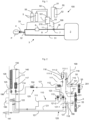
- Such an installation is shown diagrammatically in Fig. 1 .
- the NO/ N2 mixture delivered by the NO supply device is injected into the respiratory stream containing at least 21% vol. oxygen (i.e. air or O2 / N2 mixture) from the medical ventilator before being administered by inhalation to the patient in the form of a final respiratory mixture (i.e. NO/ N2 / O2 or NO/ N2 /air mixture) generally containing a few tens of ppmv of NO (ppm by volume) and at least 21% vol. of oxygen O2 , for example of the order of 1 to 80 ppmv of NO, the remainder being essentially nitrogen ( N2 ).
- a final respiratory mixture i.e. NO/ N2 / O2 or NO/ N2 /air mixture
- Such a NO administration facility is used in a hospital setting to administer NOi therapy and thus treat patients who need to inhale NO to treat their pulmonary arterial hypertension.
- NO administration facilities are given in the documents WO-A-2012/094008 , US-A-2015/320951 , US-A-2015/273175 , JP-A-H11192303 , WO-A-02/40914 And US-A-2003/116159 .
- the NO supply device In the event of a breakdown or failure of the NO supply device or the medical ventilator and/or in the event of the need to ventilate the patient with a manual ventilation bag, upon request of the nursing staff or following a minor failure of the device, the NO supply device must be able to continue to supply the NO/ N2 mixture so that the patient's treatment is not abruptly interrupted, for obvious safety reasons since an abrupt interruption of iNO treatment could be fatal to fragile patients, in particular neonates suffering from PPHN.
- a backup circuit entirely pneumatic designed to deliver an O 2 flow rate adjustable between 0 and 20 L/min and a fixed NO flow rate, for example of the order of 230 mL/min of NO/N 2 mixture, which are mixed with each other in the NO supply device before being injected into a manual ventilation bag.
- the oxygen is typically supplied by an oxygen source, such as a pressurized oxygen cylinder, connected to the NO supply device.
- Switching to “emergency mode” is carried out after activation by the user of a selection means (i.e. a device) present on the power supply device.
- a selection means i.e. a device
- NO for example an “emergency mode” selection button, the activation of which will direct the gas flows into a secondary circuit, i.e. emergency and/or manual ventilation of the NO supply device, such as that illustrated in Fig. 2 .
- a problem is to propose an improved NO supply device, which is capable of supplying a NO/N 2 /O 2 gas mixture to a patient whether in normal operating mode but also in the event of a breakdown or failure, or even when switching to manual ventilation by manual ventilation bag or BAVU, eg on request of the nursing staff or following a minor failure, preferably by observing the desired dosage, i.e. a NO/N 2 /O 2 gas mixture whose composition is not solely dependent on the oxygen flow rate.
- the present disclosure also relates to a method of treating a person, called a patient, suffering from a pathology or medical condition causing acute pulmonary arterial hypertension, in particular pulmonary vasoconstrictions in adults, adolescents or children, including newborns and babies, for example for treating persistent pulmonary hypertension of the newborn (PPHN) in a newborn, baby, child or the like, or pulmonary hypertension in a person undergoing cardiac surgery, in which an administration by inhalation is carried out to said patient in need thereof, of a gas mixture containing oxygen (preferably >21% vol), nitrogen and NO (preferably ⁇ 100 ppmv), said gas mixture being supplied by a therapeutic gas administration installation comprising a device or apparatus for supplying NO according to the invention, in particular as described above and/or below, which NO supply device is supplied with NO/N 2 mixture by at least a pressurized gas container, preferably several pressurized gas containers 5, such as NO/N 2 cylinders, and oxygen by at least one pressurized oxygen container, such as an
- Fig. 1 schematizes an embodiment of an installation 100 for administering therapeutic gas, i.e. a gas mixture based on NO, to a patient P incorporating a device or apparatus for supplying NO 1, such as that according to the present invention.
- therapeutic gas i.e. a gas mixture based on NO
- a pressurized gas container 5 arranged in parallel, each containing a gas mixture of NO and nitrogen (N 2 ), i.e. a NO/N 2 mixture, typically containing from 250 to 1000 ppmv of NO and nitrogen (N 2 ) for the remainder conditioned at a pressure of up to 180 bar or more, for example a NO/N 2 mixture, containing 450 ppmv or 800 ppmv of NO.
- gas containers 5 are commonly called NO 5 cylinders.
- the NO 5 bottles supply the NO/N 2 mixture to a NO 1 supply device, such as that according to the invention, the internal architecture of which is illustrated in Fig. 3 and Fig. 4 . They are fluidically connected to the gas supply device 1 by NO supply lines 50, i.e. gas pipes, such as flexible pipes or the like. Each NO supply line 50 is connected to an NO inlet port 101 of the NO 1 supply device to supply a main gas circuit 200 internal to the housing 199 of the NO 1 supply device (cf. Fig. 3 ).
- the NO 1 supply device also comprises an oxygen inlet port 53 fluidically connected, via an oxygen supply line 51, such as a flexible hose or the like, to an oxygen source, for example a pressurized oxygen container 52, typically an Oz bottle or, alternatively, the hospital network, i.e. an oxygen supply pipe arranged in the hospital building where the patient P is being treated.
- an oxygen source for example a pressurized oxygen container 52, typically an Oz bottle or, alternatively, the hospital network, i.e. an oxygen supply pipe arranged in the hospital building where the patient P is being treated.
- the NO 5 cylinders and the Oz 52 cylinder are equipped with a gas distribution tap 55, preferably incorporating means (i.e. a device) for gas expansion, i.e. an RDI or integrated pressure reducing valve, so as to be able to control the flow rate and/or pressure of the gas that they deliver.
- the gas distribution tap 55 is preferably protected against impacts by a protective cover.
- the installation 100 also comprises a medical ventilator 2, i.e. a respiratory assistance device, providing a flow of respiratory gas containing at least 21% vol. of oxygen, such as air or an oxygen/nitrogen mixture (N 2 /O 2 ), to the patient P.
- a medical ventilator i.e. a respiratory assistance device, providing a flow of respiratory gas containing at least 21% vol. of oxygen, such as air or an oxygen/nitrogen mixture (N 2 /O 2 ), to the patient P.
- the medical ventilator 2 is fluidically connected to the patient P via a respiratory gas circuit 3 which here has two respiratory branches 30, 31 given that it comprises an inspiratory branch 30, that is to say a gas supply line, used to bring the respiratory gas to the patient P and an expiratory branch 31 used to recover the CO2 -enriched gas exhaled by the patient P.
- a respiratory gas circuit 3 which here has two respiratory branches 30, 31 given that it comprises an inspiratory branch 30, that is to say a gas supply line, used to bring the respiratory gas to the patient P and an expiratory branch 31 used to recover the CO2 -enriched gas exhaled by the patient P.
- the two respiratory branches 30, 31 are typically flexible tubes made of polymer or the like.
- the two respiratory branches 30, 31 are, on the one hand, connected to the medical ventilator 2 and, on the other hand, connected to each other at a junction piece 32, typically a Y-piece, which is in fluid communication with a respiratory interface 4 supplying the gas to the patient P, such as a tracheal tube or the like.
- the medical ventilator 2 and the NO supply device 1 are normally electrically powered by an electric current source(s), in particular their components requiring electrical energy to operate, in particular the means (i.e. a device) for controlling 900 the NO supply device 1 and the control system of the medical ventilator 2, i.e. electronic card with microprocessor(s), or any other component, in particular the motorized internal turbine which supplies the air flow or the like, i.e. the respiratory gas.
- the electric current source can be the mains (110/220V) and/or an electric battery, preferably rechargeable.
- the NO 1 supply device makes it possible to inject the NO/N 2 mixture into the inspiratory branch 30, via an NO 11 injection conduit opening into the inspiratory branch 30 at an injection site 8, so as to produce a mixture there of the NO/N 2 flow and the flow of respiratory gas containing at least 21% O 2 , i.e. air or oxygen/nitrogen mixture, delivered by the medical ventilator 2.
- O 2 i.e. air or oxygen/nitrogen mixture
- the NO 1 supply device comprises a main outlet orifice 210 located at the outlet of its main gas circuit 200 through which the NO/N 2 flow exits the housing 199 of the NO 1 supply device and enters the NO 11 injection conduit.
- the NO 11 injection conduit is fluidically connected to the main outlet orifice 210, for example via a connector or the like.
- the therapeutic gas mixture obtained therefore contains oxygen (>21% vol.), nitrogen and a variable and adjustable concentration of NO, typically between 1 and 80 ppmv, due to the dilution of the product during the mixing of the gas flows.
- oxygen >21% vol.
- nitrogen typically contains a variable and adjustable concentration of NO, typically between 1 and 80 ppmv, due to the dilution of the product during the mixing of the gas flows.
- NO typically contains at least one or nitrogen.
- a variable and adjustable concentration of NO typically between 1 and 80 ppmv
- a gas humidifier 6 is also provided, arranged here on the inspiratory branch 30 downstream of the injection site 8, serving to humidify the flow of therapeutic gas, eg NO/N 2 /O 2 mixture, by adding water vapor, before it is inhaled by the patient P, which makes it possible to avoid or limit the drying out of the respiratory tract of the patient P during his treatment by inhalation of the gas.
- the gas humidifier 6 could also be arranged upstream of the injection site 8.
- the expiratory branch 31 used to collect the CO2- rich exhaled gases may comprise one or more other optional components, such as for example a CO2 elimination device, ie a CO2 trap, such as a hot tank or other, making it possible to eliminate the CO2 present in the gases exhaled by the patient, a filter or other.
- a CO2 elimination device ie a CO2 trap, such as a hot tank or other, making it possible to eliminate the CO2 present in the gases exhaled by the patient, a filter or other.
- a flow sensor 7 for example of the mass or pressure differential type, connected to the NO 1 supply device, in particular to the control means 900 of said NO 1 supply device, via a flow measurement line 71 of respiratory gas used to measure the gas flow coming from the ventilator 2 within the inspiratory branch 30. Determining this flow rate of the ventilator (Qv) makes it possible in particular to regulate the passage of NO through the NO 1 supply device, in particular to be able to choose the flow rate of NO/N 2 mixture to be injected according to the desired NO content, the composition of the NO/N 2 mixture coming from the bottles and the gas flow rate (i.e. air or air/O 2 ) coming from the ventilator 2.
- Qv flow rate of the ventilator
- a gas sampling line 33 fluidly connecting the NO 1 supply device to the respiratory gas circuit 3, preferably close to the Y-piece 32, for example approximately 10 to 20 cm upstream of the Y-piece 32, used to take gas samples and to check their conformity with the desired gas mixture to be administered to the patient P.
- the NO supply device 1 comprises an internal main gas circuit 200 for conveying the NO/N 2 mixture entering via the gas inlet port(s) 101 to the NO injection conduit 11.
- This main gas circuit 200 comprises means (i.e. a device) for controlling the flow rate 202 of NO/N 2 (cf. Fig. 3 and Fig. 4 ), such as valves, calibrated orifices, etc., controlled by the control means 900 of the NO supply device 1, typically one (or more) microprocessors arranged on an electronic card, the operation of which is explained below. All these components are arranged in a housing 199, i.e. a rigid external casing.
- the NO supply device 1 comprises a backup circuit 110, called a “backup” circuit, designed to deliver an adjustable Oz flow rate and a fixed NO flow rate in order to be able to ensure a supply of NO, even in the event of a breakdown or otherwise, as detailed below.
- a backup circuit 110 called a “backup” circuit, designed to deliver an adjustable Oz flow rate and a fixed NO flow rate in order to be able to ensure a supply of NO, even in the event of a breakdown or otherwise, as detailed below.
- Fig. 2 schematizes an embodiment of the emergency circuit 110 or secondary circuit of a conventional NO supply device 1.
- the main gas circuit 200 of the NO 1 supply device which conveys the NO/N 2 mixture during normal operation of the device 1, i.e. in the absence of a breakdown or the like, is not shown in order not to unnecessarily complicate the diagram and complicate its understanding.
- this main gas circuit 200 which is arranged in the housing 199, comprises, as shown, the one illustrated in Fig. 3 or Fig.
- a main NO line 201, 203 comprising at least one portion of upstream conduit 201, namely here two portions of upstream conduit 201 arranged in parallel, since 2 NO 5 bottles are connected to the NO 1 supply device, as illustrated in Fig. 2 to Fig. 4 , and moreover at least one downstream portion 203.
- the emergency circuit 110, 120 the operation of which can be entirely pneumatic, which is also arranged in the housing 199, comprises an emergency NO circuit 110 and an emergency Oz circuit 120 which each comprise gas pipes, passages or conduits for conveying the various gases or gas mixtures in the housing 199.
- the emergency NO 110 circuit is supplied with NO/N 2 by at least one section of NO inlet pipe 111-1, 111-2, namely here two sections of NO inlet pipe 111-1, 111-2 arranged in parallel, themselves supplied by the two NO inlet ports 101 to which the NO 5 bottles are connected, via the supply line 50, as explained above.
- the inlet pipe section(s) 111-1, 111-2 are fluidically connected to the upstream pipe portions 201 (partially shown in Fig. 2 ) downstream of a filter 115 located immediately downstream of each NO inlet port 101 in the upstream conduit portion(s) 201, as detailed in Fig. 3 .
- a check valve 116 is arranged in each inlet pipe section 111-1, 111-2. These two inlet pipe sections 111-1, 111-2 join downstream of the check valves 116 to form a common emergency NO line 111, from a junction site 111-3.
- Each upstream conduit portion 201 further comprises a pressure measuring means 118, such as a strain gauge pressure sensor ( silicon pressure sensor in English) or the like, used to verify that there is a pressure in the upstream conduit portion 201 reflecting the presence of a connected bottle and therefore also to verify the quantity of gas it contains in order to decide whether to change it (if the bottle is almost empty) and switch to the other gas bottle.
- Said pressure measuring means 118 is located downstream of the filter 115.
- the device 1 may comprise only one NO inlet port 101 and therefore only one portion of upstream conduit 201 and only one section of inlet pipe 111-1.
- only one oxygen supply line 51 such as a flexible pipe or the like, can be fluidically connected thereto, which is supplied with NO/N 2 mixture by one or more NO 5 bottles.
- the emergency NO line 111 is used to convey the NO/ N2 mixture under pressure coming, via the inlet pipe sections 111-1, 111-2, from the upstream conduit portions 201 supplied by the NO5 cylinders delivering the NO/ N2 mixture at a pressure of the order of 3 to 6 bar relative at the outlet of the RDI 55.
- the emergency NO line 111 further comprises a first pressure regulator 112, downstream of the junction site 111-3, for reducing or controlling the pressure of the NO/N 2 mixture, for example for delivering a reduced pressure equal to approximately 3.2 bar relative, and a pneumatic valve 113 for controlling the circulation of the NO/N 2 mixture.
- a pneumatic valve 113 is located downstream of the first pressure regulator 112, considering the direction of circulation of the gas, knowing that the gaseous NO/N 2 mixture circulates in the direction going from each gas inlet port 101 to the pressure regulator 112.
- the opening of the pneumatic valve 113, and therefore the passage of the NO/N 2 flow, is controlled by the pressure of the oxygen flow supplied by the main Oz line 121 via the second section of conduit 121-2, as explained below.
- the emergency NO line 111 Downstream of the pneumatic valve 113, the emergency NO line 111 comprises a calibrated orifice device 114 or the like for regulating the gas flow rate, i.e. of the NO/N 2 mixture, and an NO flow rate indicator device 117 for checking that the NO/N 2 mixture flow rate is indeed equal to the expected fixed value, for example of the order of 230 mL/min.
- the emergency oxygen circuit 120 comprises a main O2 line 121 used to convey the oxygen into the housing 199, which is supplied by the Oz inlet port 53 to which the Oz bottle 52 is connected, via the supply line 51 which brings the gaseous oxygen at a pressure typically between 3 and 6 bar.
- the main Oz line 121 is connected at a junction site 130 to the emergency NO line 111, downstream of the NO flow indicator device 117 so as to produce a mixture of the oxygen flow at an adjustable flow rate, as explained below, and the NO/N 2 flow which has a fixed flow rate of the order of 230 mL/min for example.
- the main O 2 line 121 also comprises a filter 106, arranged immediately downstream of the Oz inlet port 53, as well as a first control valve 122 and a second pneumatic control valve 123. It also comprises a pressure measuring means 118, such as a strain gauge pressure sensor, as explained above.
- the first control valve 122 typically of the all-or-nothing type, makes it possible to control the circulation of the oxygen flow in the main Oz line 121. It is controlled by an actuating means 195, such as a rotary selector, a push button, a selection key or the like, operable by the user, such as a healthcare worker, when he wishes to start or stop the emergency circuit 110, 120.
- an actuating means 195 such as a rotary selector, a push button, a selection key or the like, operable by the user, such as a healthcare worker, when he wishes to start or stop the emergency circuit 110, 120.
- a first section of conduit 121-1 is fluidically connected to the main Oz line 121 between the Oz inlet port 53, in particular downstream of the filter 106, and the first control valve 122.
- the first section of conduit 121-1 makes it possible to pneumatically control the second pneumatic control valve 123.
- the first control valve 122 opens and then allows the gas to pass towards the second control valve 123. Due to the pressure of the oxygen arriving at the second control valve 123, sufficient force will be generated to allow the control valve 123 to be opened due to the pressure provided by the first section of conduit 121-1, which will then open the second control valve 123 and then allow the oxygen to pass into the downstream part of the oxygen circuit 120 which is located downstream of the second control valve 123.
- the oxygen then continues its route in the main Oz line 121 through a second pressure regulator 124 to reduce or control the pressure of the oxygen flow, for example to obtain a pressure of 1.6 bar abs relative.
- the flow rate of the O 2 flow can then be adjusted, for example between 5 and 20 L/min, by means (ie a device) for adjusting the Oz flow rate 125, such as a rotating disk with calibrated orifices or the like, arranged on the main Oz line 121 downstream of the second pressure regulator 124.
- the selection of the desired O 2 flow rate can be operated by the user via a flow rate selection means 196, such as a rotary knob or the like, carried by the housing 199 of the device (or according to another embodiment, a selection of an Oz flow rate via a key or the like displayed on a display screen 950), which flow rate selection means 196 cooperates with the Oz flow rate adjustment means 125.
- a flow rate selection means 196 such as a rotary knob or the like, carried by the housing 199 of the device (or according to another embodiment, a selection of an Oz flow rate via a key or the like displayed on a display screen 950), which flow rate selection means 196 cooperates with the Oz flow rate adjustment means 125.
- the oxygen flow rate can then be checked via an O 2 flow rate indicator device 126, such as a ball rotameter or the like, arranged downstream of the Oz flow rate adjustment device or means 125.
- the oxygen flow obtained can then mix with the NO/N 2 flow from the junction site 130 where the main Oz line 121 connects to the emergency NO line 111, as already mentioned.
- This emergency circuit 110, 120 being entirely pneumatic, in order to control the circulation of NO/N 2 within the emergency NO line 111, a second section of conduit 121-2 is provided which is fluidically connected to the main Oz line 121 between the second control valve 123 and the second pressure regulator 124.
- This second section of conduit 121-2 controls the pneumatic valve 113 of the emergency NO circuit 110 thanks to the oxygen pressure which it contains.
- the second control valve 123 opens after actuation by the user of the actuation means 195 and opening of the first control valve 122, as explained above, the flow of pressurized oxygen will be able to pass through the second control valve 123, then spread and transit downstream of the latter, in particular in the second section of conduit 121-2 to then act pneumatically on the pneumatic valve 113 of the NO circuit 110 and open it, thus releasing the passage of the NO/N 2 mixture and its circulation in the downstream part of the emergency NO line 111 located downstream of the pneumatic valve 113.
- the first control valve 122, the second control valve 123 and the pneumatic valve 113 are for example pilot-operated pneumatic valves of the poppet and spring type.
- the activation of the actuation means 195 by the user leads to a quasi-synchronized and/or quasi-simultaneous release of the NO/N 2 and Oz mixture flows within the backup NO circuit 110 and the backup oxygen circuit 120, thus leading to their mixing from and downstream of the junction site 130, that is to say in the common emergency line 140 which opens at an emergency outlet 141, i.e. a secondary outlet, for example carried by a connection connector or the like, that is to say an outlet connection, to which a manual gas insufflator can be connected, that is to say a manual ventilation balloon or the like.
- an emergency outlet 141 i.e. a secondary outlet, for example carried by a connection connector or the like, that is to say an outlet connection, to which a manual gas insufflator can be connected, that is to say a manual ventilation balloon or the like.
- this emergency or secondary gas circuit 110, 120 is entirely pneumatic since it only uses gas conduits and pneumatic valves to control the gas flows.
- the NO concentration varies between 8 and 32 ppmv for an oxygen flow rate of between 5 and 20 L/min, whereas for a NO/ N2 mixture at 450 ppmv of NO, the NO concentration varies between 4.5 and 18 ppmv for the same oxygen flow rate.
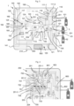
- the improved NO 1 supply device is provided as illustrated in Fig. 3 and Fig. 4 which schematize an embodiment of the internal architecture of a NO 1 supply device according to the present invention.
- the NO 1 supply device of Fig. 3 includes the fully pneumatic elements of the emergency gas circuit 110, 120 of Fig. 2 , these bear the same references and are therefore not re-explained below.
- the NO 1 supply device of the invention also comprises the internal main gas circuit 200 serving, during normal operation of the device 1, to supply the NO/N 2 mixture, via the NO injection conduit 11, to the inspiratory branch 30 of the ventilation circuit 3 which is connected and supplied by the medical ventilator 2, with respiratory gas, i.e. air or N 2 /O 2 mixture, as explained above in connection with the Fig. 1 .
- respiratory gas i.e. air or N 2 /O 2 mixture
- the main gas circuit 200 comprises at least one upstream conduit portion 201, namely here two upstream conduit portions 201 to which the inlet pipe sections 111-1, 111-2 are fluidically connected, at a connection site 205 located between the filter 115 and the non-return valve 116 of each inlet pipe section 111-1, 111-2, as shown in Fig. 3 .
- upstream conduit 201 is necessary.
- the upstream conduit portion(s) 201 make it possible to convey the NO/N 2 mixture coming from the inlet pipe sections 111-1, 111-2 to means (i.e. a device) for controlling the NO/N 2 flow rate 202 making it possible to control the flow rate of the NO/N 2 mixture stream which must then be supplied to the injection conduit 11.
- means i.e. a device for controlling the NO/N 2 flow rate 202 making it possible to control the flow rate of the NO/N 2 mixture stream which must then be supplied to the injection conduit 11.
- An embodiment of the NO/N 2 flow rate control means 202 is detailed in Fig. 4 .
- the gas flow After passing through the NO/N 2 flow control means 202, the gas flow is conveyed by a downstream conduit portion 203 of the main NO line 201, 203 which brings it and supplies it to the injection conduit 11, via the main outlet orifice 210 which is located at the outlet end of the downstream conduit portion 203 of the main gas circuit 200.
- a first 3-way solenoid valve 204 is arranged on the downstream conduit portion 203 of the main NO line 201, 203 between the NO/N flow control means 202 and the main outlet orifice 210, i.e. it is connected by 2 of these 3 ways to the downstream conduit portion 203 so as to control the circulation of the gas in the downstream conduit portion 203. It is also connected, via its third way, to the emergency NO line 111, downstream of the pneumatic valve 113 which is itself located downstream of the first pressure regulator 112, considering the direction of circulation of the gas, i.e. NO/N 2 mixture, in the emergency NO line 111.
- the emergency NO line 111 comprises a second 2-way solenoid valve 150 which is normally in the open position, i.e. it allows the gas to circulate within the emergency NO line 111, and the calibrated orifice device 114 or the like for regulating the gas flow, i.e. of the NO/N 2 mixture, which on Fig. 2 is arranged near the NO flow indicator device 117.
- the second solenoid valve 150 is therefore located between the pneumatic valve 113 and the first 3-way solenoid valve 204.
- the second solenoid valve 150 is normally in the open position but can be controlled by the control means 900, in particular in the event of activation of the emergency mode in the event of a slight failure, as explained below, or in the event of the need to ventilate a patient using the manual insufflator to perform alveolar recruitment maneuvers for example.
- first 3-way solenoid valve 204 and the second 2-way solenoid valve 150 can be replaced by a single 5-way solenoid valve which would be installed in place of the first 3-way solenoid valve 204 (the second solenoid valve 150 would then be removed).
- the NO 1 supply device of the invention finally comprises means (i.e. a device) for measuring the oxygen flow rate 160 arranged on the main Oz line 121 between the second pressure regulator 124 and the device or means for adjusting the O 2 flow rate 125.
- means i.e. a device for measuring the oxygen flow rate 160 arranged on the main Oz line 121 between the second pressure regulator 124 and the device or means for adjusting the O 2 flow rate 125.
- These oxygen flow measurement means 160 may comprise a flow sensor or a differential pressure sensor whose pressure taps 161, 162 are connected upstream and downstream of a flow restriction 163, such as a venturi system, a calibrated orifice or other, in order to measure a differential of pressure ( ⁇ P), i.e. a pressure loss, allowing us to deduce an oxygen flow rate (Q O2 ).
- a flow restriction 163 such as a venturi system, a calibrated orifice or other
- Fig. 4 represents a detailed embodiment of the NO/N 2 flow control means 202 for controlling the flow rate of NO/N 2 mixture within the main gas circuit 200 arranged in the housing 199 of the NO 1 supply device.
- each upstream conduit portion 201 comprises a first control valve 700 arranged upstream of the junction site of the two upstream conduit portions 201, which serves to authorize or stop the circulation of the NO/N 2 mixture flow brought by one or the other of the upstream conduit portions 201.
- the common section 201-1 is then divided into two secondary sections 201-2 arranged in parallel to each other, each of which comprises a pressure regulating device 701 and a pressure sensor 702.
- the two secondary sections 201-2 are in turn divided into several sub-sections 201-3 which are also arranged in parallel with each other, namely here two sub-sections 201-3.
- Each sub-section 201-3 comprises a second control valve 703.
- Sub-sections 201-3 also comprise additional flow control means (i.e. a device) 704, for example a calibrated orifice(s) or the like, making it possible to adjust the flow rate to a desired flow rate value.
- the NO/N 2 flow control means 202 may comprise more sub-sections 201-3, in particular each equipped with a control valve 703 and additional flow control means 704, typically a calibrated orifice, in order to enable a greater variety of NO flow rates to be delivered, if necessary.
- the control valve(s) 703 is an all-or-nothing (TOR) type valve.
- TOR all-or-nothing
- the gas flow rate circulating therein is fixed and depends on the pressure of the pressure regulator 701, i.e. a pressure reducer, and on the section of the calibrated orifice.
- control means 900 of the NO 1 supply device such as an electronic card carrying one or more microprocessors implementing one or more algorithms, control the first control valves 700 and the second control valves 703 in order to direct the gases into the appropriate sections to obtain the desired NO dosage.
- the desired NO content is selected by the user via means (i.e. a device) for selecting the NO content (not shown diagrammatically) arranged on the device, for example one or more keys, sliders, selection buttons, in particular a rotary button, or the like, which make it possible to select or set a desired NO content.
- means i.e. a device for selecting the NO content (not shown diagrammatically) arranged on the device, for example one or more keys, sliders, selection buttons, in particular a rotary button, or the like, which make it possible to select or set a desired NO content.
- the NO 1 supply device of the invention is equipped with an information display screen 950, typically a digital screen, preferably a touch screen, in color or in black and white, configured to display the desired NO content value and/or other information, such as the NO content in the NO 5 bottles or the NO or O 2 flow rate values, and for example also the NO 2 concentration, the flow rate delivered by the fan, etc.
- an information display screen 950 typically a digital screen, preferably a touch screen, in color or in black and white, configured to display the desired NO content value and/or other information, such as the NO content in the NO 5 bottles or the NO or O 2 flow rate values, and for example also the NO 2 concentration, the flow rate delivered by the fan, etc.
- the information display screen 950 is a touch-controlled digital screen and the NO content selection means are touch-activated selection keys, displayed on the touch-activated digital display screen 950.
- the selection or setting of the desired NO concentration is therefore done by digital pressure by the user on the touch-activated selection key(s) displayed on the display screen 950.
- control means 900 of the NO 1 supply device calculate the flow rate of NO/N 2 mixture to be supplied, in particular as a function of other parameters, such as the NO content of the NO/N 2 mixture coming from the bottles 5, and also the flow rate of respiratory gas (typically air or air/O 2 ) supplied by the ventilator 2, and then determine which control valves 700, 703 must be opened or closed in order to direct the gases into the sections adapted to obtaining the fixed NO dosage.
- the control means 900 of the NO 1 supply device calculate the flow rate of NO/N 2 mixture to be supplied, in particular as a function of other parameters, such as the NO content of the NO/N 2 mixture coming from the bottles 5, and also the flow rate of respiratory gas (typically air or air/O 2 ) supplied by the ventilator 2, and then determine which control valves 700, 703 must be opened or closed in order to direct the gases into the sections adapted to obtaining the fixed NO dosage.
- respiratory gas typically air or air/O 2
- the sub-sections 201-3 then come together, upstream of the first 3-way solenoid valve 204, in a single line which forms the downstream conduit portion 203 of the main gas circuit 200. It may include a pressure sensor 705 or the like, upstream of the first solenoid valve 204, in order to be able to possibly correct the flow rate which depends on the pressure variation ( ⁇ P) of the gas when it passes through the additional flow control means 704, typically one or more calibrated orifices.
- ⁇ P pressure variation
- the NO 1 supply device of the invention further comprises a purge line 800 communicating with the outside via a purge orifice 802 arranged in the housing 199.
- the purge line 800 branches into two purge sections 801 connecting to the two upstream conduit portions 201 in order to be able to perform a gas purge of these two upstream conduit portions 201.
- Each purge section 801 comprises a purge valve 803 controlled by the control means 900 so as to be able to eliminate all the NO 2 species that may form in the residual gas present in the pipes by oxidation of the NO molecules by oxygen, when the device 1 is not in operation, that is to say is not used.
- the NO/N 2 mixture travels in the main gas circuit 200 of the NO 1 supply device of the invention, via the NO/N 2 flow rate control means 202, from one of the gas inlet ports 101 to the main outlet port 210 which supplies the NO/N 2 mixture to the NO injection conduit 11 so as to then be able to inject it at the desired NO concentration, into the inspiratory branch 30 of the ventilation circuit 3 connected to the medical ventilator 2, as explained above in connection with Fig. 1 And Fig. 4 .
- the second 2-way solenoid valve 150 is in the “normally open” position, i.e. it does not interrupt the passage of gas in the emergency NO line 111, and the first 3-way solenoid valve 204 is in the “normal operating” position, authorizing the passage of the gas flow in the downstream conduit portion 203 to the main outlet orifice 210.
- the first solenoid valve 204 is controlled by the control means 900 to authorize or stop any passage of NO/N 2 mixture coming from the NO flow control (i.e. adjustment) means 202.
- the second 2-way solenoid valve 150 remains in the “normally open” position and the first 3-way solenoid valve 204 remains in the “normal operating” position so as to allow circulation of the gas flow in the downstream conduit portion 203 to the main outlet orifice 210. This allows, after actuation by the user of the actuation means 195, a switch to fully pneumatic emergency mode, as explained in connection with Fig. 2 .
- the failure of the NO 1 supply device of the invention is a minor failure not leading to a total loss of electrical energy and/or to a stoppage of operation of the control means 900 of the device 1 and/or if the healthcare personnel decides to ventilate the patient via a manual ventilation bag while wishing to respect the NO dosage, then the NO 1 supply device of the invention and more particularly the control means 900 and the display screen 950 remain supplied with electrical energy by the electrical energy supply means, therefore the control means 900 remain able to operate.
- the user wishing to switch device 1 to emergency mode or BAVU ventilation to ensure a supply of gas to the patient via a manual ventilation bag or BAVU, will activate, as previously, the means actuating valve 195, which will then cause the first control valve 122 to open, thereby allowing the flow of oxygen in the main Oz line 121 to flow to the second control valve 123, which will then also open and allow oxygen to pass into the downstream part of the oxygen circuit 120, located downstream of the second control valve 123, as explained above in connection with Fig. 2 .
- the oxygen flow rate measuring means 160 which are arranged on the main Oz line 121 downstream of the second pressure regulator 124 will then be able to measure the oxygen flow rate (O O2 ) and transmit this Oz flow rate measurement (i.e. signal or value) to the control means 900 in order to calculate the NO/N 2 flow rate to be supplied as explained below.
- the oxygen flow can then continue its path to the junction site 130 where the O2 /NO/ N2 mixture takes place, via the Oz flow rate adjustment means 125 and the Oz flow rate indicator device 126, such as a ball rotameter or the like, as already explained.
- the actuating means 195 is electrically connected to the control means 900 and configured to provide them with actuating information, namely an activation signal corresponding to the position of the actuating means 195, namely in emergency mode (i.e. emergency activated) or in normal mode (i.e. emergency not activated).
- This activation signal is electrically provided to the control means 900 of the NO 1 supply device of the invention, which receive it and process it to determine whether the actuating means 195 has been actuated by the user in order to trigger the emergency mode or BAV ventilation, with a view to carrying out ventilation of the patient via a manual ventilation bag connected to the secondary outlet, i.e. the emergency outlet 141, NO 1 supply device of the invention, for example via a flexible hose.
- control means 900 of the NO 1 supply device of the invention which remain supplied with electrical energy (i.e. electric current), feedback, in response to this signal, on the NO/N 2 flow rate control means 202 to supply the NO/N 2 mixture at the desired flow rate and on the first 3-way solenoid valve 204 to authorize the passage of the NO/N 2 flow from the portion of conduit downstream 203 of the main gas circuit 200 to the downstream part of the emergency NO line 111 located downstream of the first solenoid valve 204 and conveying the flow of NO/N 2 via the NO flow indicator device 117, to the mixing site 130 where the main Oz line 121 and the emergency NO line 111 join, as already explained.
- electrical energy i.e. electric current
- the NO/N 2 mixture being produced within the NO/N 2 flow rate control means 202 it is possible to set the most suitable NO flow rate.
- This NO/N 2 mixture flow rate to be supplied by the NO/N 2 flow rate control means 202 can be calculated by the control means 900 of the NO 1 supply device of the invention from the desired final NO content, the composition of the NO/N 2 mixture in the bottles 5 and the oxygen flow rate measured by the oxygen flow rate measuring means 160 which are arranged on the main Oz line 121 downstream of the second pressure regulator 124.
- the desired final NO content is therefore, in this case, chosen by the user via the NO content adjustment means arranged on the device, preferably one or more digital keys with digital actuation displayed on the digital display screen 950 which also remains supplied with electric current.
- control means 900 use this adjusted NO content value, the concentration of NO in the NO/N 2 mixture supplied by the NO 5 cylinders and the measured Oz flow value to determine the NO/N 2 flow rate to be supplied and act accordingly on the NO/N 2 flow control means 202, in particular the first control valves 700 and the second control valves 703, to provide the adequate NO/N 2 flow rate by controlling the passage of gas in particular in the secondary sections 201-2, the pressure regulating device 701, the two secondary sections 201-2 and the sub-sections 201-3 comprising additional flow control means 704, for example calibrated orifices or the like, allowing the flow rate to be adjusted to a desired flow rate value.
- the oxygen flow rate measuring means 160 on the main Oz line 121, downstream of the second pressure regulator 124, which measure the oxygen flow rate (Q O2 ) and transmit this Oz flow rate measurement to the control means, the latter can calculate a NO/ N2 flow rate setpoint to be provided by the NO/ N2 flow rate control means 202, taking into account not only the NO setpoint set by the user but also the concentration of NO in the NO/ N2 mixture coming from the NO5 cylinders.
- the control means 900 of the NO 1 supply device of the invention are also configured to also act on the second 2-way solenoid valve 150, which is normally in the open position, to close it and thus prevent the NO/N 2 mixture from being able to circulate within the emergency NO line 111 and supply the downstream part of the emergency NO line 111 located downstream of the first solenoid valve 204.
- the NO/N 2 /O 2 mixture thus obtained is then, as previously, conveyed by the common emergency line 140 which opens at an emergency outlet 141, i.e. secondary outlet, to provide the emergency gas mixture formed of NO/N 2 /O 2 and to be able to then bring it, via a flexible conduit or the like, to a manual ventilation balloon to manually ventilate the patient with the NO/ N2 / O2 gas mixture having the desired dosage
- the NO1 supply device has a higher level of safety by allowing the NO content to be adjusted more precisely in the event of a failure or slight breakdown, without loss of power supply, or when the user wants to switch to manual ventilation of the patient by BAVU.
- the NO 1 supply device is particularly suitable for use within an installation 100 for administering therapeutic gas based on NO ( ⁇ 100 ppmv), Oz (> 21% vol) and nitrogen to a patient P, such as the installation 100 of Fig. 1 , used to treat one or more patients suffering from a pathology or medical condition causing acute pulmonary arterial hypertension, in particular pulmonary vasoconstrictions in adults or children, including newborns, for example to treat PPHN in a newborn, or pulmonary hypertension in a person undergoing heart surgery.
- a pathology or medical condition causing acute pulmonary arterial hypertension in particular pulmonary vasoconstrictions in adults or children, including newborns, for example to treat PPHN in a newborn, or pulmonary hypertension in a person undergoing heart surgery.
- the present disclosure therefore also relates to a method of treating a person, called a patient, suffering from a pathology or a medical condition causing acute pulmonary arterial hypertension, in particular pulmonary vasoconstrictions in adults or children, including newborns, for example for treating persistent pulmonary hypertension of the newborn (PPHN) in a newborn, baby or the like, or pulmonary hypertension in a person undergoing cardiac surgery, in which an administration by inhalation is carried out to said patient in need thereof, of a gas mixture containing oxygen (preferably >21% vol), nitrogen and NO (preferably ⁇ 100 ppmv), said mixture gas being supplied by a therapeutic gas administration installation 100 comprising a NO 1 supply device according to the invention, which NO 1 supply device is supplied with NO/N 2 mixture by at least one pressurized gas container 5, preferably several pressurized gas containers 5, such as NO/N 2 cylinders, and with oxygen by at least one pressurized oxygen container 52, such as an O 2 cylinder, and which NO 1 supply
- NO 1 supply device is supplied with NO/
Landscapes
- Health & Medical Sciences (AREA)
- Pulmonology (AREA)
- Engineering & Computer Science (AREA)
- Hematology (AREA)
- Animal Behavior & Ethology (AREA)
- Veterinary Medicine (AREA)
- Emergency Medicine (AREA)
- Anesthesiology (AREA)
- Biomedical Technology (AREA)
- Heart & Thoracic Surgery (AREA)
- Public Health (AREA)
- Life Sciences & Earth Sciences (AREA)
- General Health & Medical Sciences (AREA)
- Automation & Control Theory (AREA)
- Physics & Mathematics (AREA)
- General Physics & Mathematics (AREA)
- Respiratory Apparatuses And Protective Means (AREA)
- Ventilation (AREA)
- Pharmaceuticals Containing Other Organic And Inorganic Compounds (AREA)
- Nozzles (AREA)
Claims (15)
- NO-Abgabevorrichtung (1), welche umfasst:- Ansteuermittel (900), die durch Mittel zur Abgabe elektrischer Energie mit elektrischer Energie gespeist werden,- einen Hauptgaskreislauf (200), der mindestens eine NO-Hauptleitung (201, 203) umfasst, die mindestens einen NO-Einlassanschluss (101) mit einer Hauptauslassöffnung (210) fluidisch verbindet, um ein NO/N2-Gemisch von dem mindestens einen NO-Einlassanschluss (101) zu der Hauptauslassöffnung (210) zu befördern, wobei die NO-Hauptleitung (201, 203) NO/N2-Durchflusssteuermittel (202) umfasst, die durch die Ansteuermittel (900) angesteuert werden,- einen Hilfskreislauf (110, 120), der einen NO-Hilfskreislauf (110) und einen O2-Hilfskreislauf (120) umfasst, wobei:a) der NO-Hilfskreislauf (110) eine NO-Hilfsleitung (111) in Fluidkommunikation mit der NO-Hauptleitung (201, 203) umfasst, wobei die NO-Hilfsleitung (111) ein pneumatisches Ventil (113), das die Steuerung des Stroms des NO/N2-Gemisches in der NO-Hilfsleitung (111) ermöglicht, und ein zweites Magnetventil (150), das sich normalerweise in einer geöffneten Stellung befindet, umfasst, wobei das zweite Magnetventil (150) von den Ansteuermitteln (900) gesteuert wird, undb) der O2-Hilfskreislauf (120) eine O2-Hauptleitung (121) in Fluidkommunikation mit einem O2-Einlassanschluss (53) umfasst, wobei die O2-Hauptleitung (121) umfasst:• ein erstes Steuerventil (122), das von einem durch einen Benutzer betätigbaren Betätigungsmittel (195) gesteuert wird, um den Strom des Sauerstoffflusses in der O2-Hauptleitung (121) zu steuern, wobei das Betätigungsmittel (195) ferner dafür ausgelegt ist, als Reaktion auf eine Betätigung des Betätigungsmittels (195) durch den Benutzer ein Aktivierungssignal an die Ansteuermittel (900) zu liefern, und• ein zweites, pneumatisches Steuerventil (123), das stromabwärts des ersten Steuerventils (122) angeordnet ist,und wobei die Ansteuermittel (900) mindestens einen Mikroprozessor umfassen und dafür ausgelegt sind, als Reaktion auf den Empfang des Aktivierungssignals, das nach Betätigung des Betätigungsmittels (195) durch den Benutzer bereitgestellt wird:• das zweite Magnetventil (150) des NO-Hilfskreislaufs (110) zu steuern, um jeglichen Strom von NO/N2-Gemisch durch das zweite Magnetventil (150) zu unterbrechen,• die NO/N2-Durchflusssteuermittel (202) zu steuern, um den Durchfluss des NO/N2-Gemisches in dem Hauptgaskreislauf (200) zu regeln, und• ein erstes Magnetventil (204), das in der NO-Hauptleitung (201, 203) stromabwärts der NO/N2-Durchflusssteuermittel (202) und in der NO-Hilfsleitung (111) des NO-Hilfskreislaufs (110) stromabwärts des pneumatischen Ventils (113) und des zweiten Magnetventils (150) angeordnet ist, zu steuern, um den Fluss von NO/N2-Gemisch, der von den NO/N2-Durchflusssteuermitteln (202) kommt, in einen stromabwärtigen Abschnitt der NO-Hilfsleitung (111) zu führen, der an die O2-Hauptleitung (121) angeschlossen (130) ist, um eine gemeinsame Hilfsleitung (140) in Fluidkommunikation mit einem Hilfsauslass (141) zu bilden.
- Vorrichtung nach Anspruch 1, dadurch gekennzeichnet, dass sie ferner umfasst:- Messmittel für den Sauerstoffdurchfluss (160), die stromabwärts des zweiten Steuerventils (123) angeordnet sind und dafür ausgelegt sind, mindestens einen Messwert des Sauerstoffdurchflusses an die Ansteuermittel (900) zu liefern, und- Regelungsmittel für den O2-Durchfluss (125), die stromabwärts der Messmittel für den Sauerstoffdurchfluss (160) angeordnet sind.
- Vorrichtung nach einem der Ansprüche 1 oder 2, dadurch gekennzeichnet, dass:- sie Regelungsmittel für den NO-Gehalt umfasst, die dafür ausgelegt sind, einem Benutzer zu ermöglichen, einen gewünschten NO-Gehalt zu wählen, und den gewünschten NO-Gehalt an die Ansteuermittel (900) zu liefern, und- die Ansteuermittel (900) dafür ausgelegt sind, einen zu liefernden Durchfluss von NO/N2-Gemisch zu berechnen, der dem gewünschten NO-Gehalt entspricht, und die NO/N2-Durchflusssteuermittel (202) so anzusteuern, dass sie den berechneten Durchfluss von NO/N2-Gemisch liefern.
- Vorrichtung nach den Ansprüchen 2 und 3, dadurch gekennzeichnet, dass die Ansteuermittel (900) dafür ausgelegt sind, den zu liefernden Durchfluss von NO/N2-Gemisch aus dem gewünschten NO-Gehalt, dem von den Messmitteln für den Sauerstoffdurchfluss (160) gemessenen Sauerstoffdurchfluss und einem NO-Gehalt in dem NO/N2-Gemisch, das von der NO-Hauptleitung (201, 203) befördert wird, zu berechnen.
- Vorrichtung nach Anspruch 3, dadurch gekennzeichnet, dass sie ferner ein digitales Touchscreen-Display (950) umfasst und die Regelungsmittel für den NO-Gehalt mindestens eine auf dem Display (950) angezeigte Touch-Wahltaste, vorzugsweise auf dem Display (950) angezeigte Touch-Wahltasten, umfassen.
- Vorrichtung nach Anspruch 5, dadurch gekennzeichnet, dass die mindestens eine Touch-Wahltaste dafür ausgelegt ist, dem Benutzer zu ermöglichen, einen gewünschten NO-Gehalt zwischen 1 und 80 ppmv festzulegen oder auszuwählen.
- Vorrichtung nach Anspruch 4, dadurch gekennzeichnet, dass der NO-Gehalt in dem NO/N2-Gemisch, das von der NO-Hauptleitung (201, 203) befördert wird, zwischen 100 und 1000 ppmv beträgt.
- Vorrichtung nach Anspruch 1, dadurch gekennzeichnet, dass die O2-Hauptleitung (121) dafür ausgelegt ist, mit dem pneumatischen Ventil (113) pneumatisch zusammenzuwirken, um nach Betätigung des Betätigungsmittels (195) durch den Benutzer den Durchgang des NO/N2-Gemisches in der NO-Hilfsleitung (111) zuzulassen.
- Vorrichtung nach Anspruch 1, dadurch gekennzeichnet, dass die Ansteuermittel (900) ferner dafür ausgelegt sind, bei Nichtbetätigung des Betätigungsmittels (195) durch den Benutzer einen Normalbetrieb der Vorrichtung (1) zu gewährleisten, indem die NO/N2-Durchflusssteuermittel (202) so angesteuert werden, dass das NO/N2-Gemisch zwischen dem mindestens einen NO-Einlassanschluss (101) und der Hauptauslassöffnung (210) durch den Hauptgaskreislauf (200) befördert wird.
- Vorrichtung nach Anspruch 1, dadurch gekennzeichnet, dass das erste Magnetventil (204) mehrere Wege, vorzugsweise 3 Wege, umfasst.
- Vorrichtung nach Anspruch 1, dadurch gekennzeichnet, dass die NO-Hilfsleitung (111) des NO-Hilfskreislaufs (110) und die O2-Hauptleitung (121) des O2-Hilfskreislaufs (120) an einer Verbindungsstelle (130), die sich stromabwärts der Regelungsmittel für den O2-Durchfluss (125) der O2-Hauptleitung (121) und stromabwärts des zweiten Magnetventils (150) der NO-Hilfsleitung (111) befindet, fluidisch aneinander angeschlossen sind.
- Vorrichtung nach Anspruch 1, dadurch gekennzeichnet, dass der Hilfsauslass (141) dafür ausgelegt ist, an einen manuellen Insufflator, wie etwa einen manuellen Beatmungsbeutel oder BAVU, fluidisch angeschlossen zu werden.
- Anlage (100) zur Verabreichung von therapeutischem Gas, das NO enthält, an einen Patienten (P), welche eine NO-Abgabevorrichtung (1) nach einem der vorhergehenden Ansprüche umfasst, die durch mindestens einen Druckgasbehälter (5) mit NO/N2-Gemisch und durch einen Sauerstoffdruckbehälter (52) mit Sauerstoff gespeist wird, wobei die NO-Abgabevorrichtung (1) abgibt:- entweder ein NO/N2-Gemisch über die Hauptauslassöffnung (210) an einen Atemgaskreislauf (3), der an ein medizinisches Beatmungsgerät (2) angeschlossen ist,- oder ein NO/N2/O2-Gemisch über die Hilfsöffnung (141) an einen manuellen Insufflator oder BAVU.
- Anlage nach Anspruch 13, dadurch gekennzeichnet, dass der mindestens eine Druckgasbehälter (5) ein NO/N2-Gemisch enthält, das 100 bis 1000 ppmv NO enthält, wobei der Rest Stickstoff ist.
- Anlage nach Anspruch 13, dadurch gekennzeichnet, dass die NO-Abgabevorrichtung (1) einen Hilfsauslass (141) umfasst, der über eine Anschlussleitung fluidisch an einen manuellen Insufflationsbeutel angeschlossen ist.
Applications Claiming Priority (1)
| Application Number | Priority Date | Filing Date | Title |
|---|---|---|---|
| FR2202056A FR3133317B1 (fr) | 2022-03-09 | 2022-03-09 | Appareil de délivrance de NO avec système de ventilation manuelle |
Publications (2)
| Publication Number | Publication Date |
|---|---|
| EP4241817A1 EP4241817A1 (de) | 2023-09-13 |
| EP4241817B1 true EP4241817B1 (de) | 2024-10-23 |
Family
ID=81927666
Family Applications (1)
| Application Number | Title | Priority Date | Filing Date |
|---|---|---|---|
| EP23159304.7A Active EP4241817B1 (de) | 2022-03-09 | 2023-03-01 | Vorrichtung zur bereitstellung von no mit einem backup-system zur bereitstellung von no in einem notbetrieb |
Country Status (8)
| Country | Link |
|---|---|
| US (1) | US20230285709A1 (de) |
| EP (1) | EP4241817B1 (de) |
| JP (1) | JP2023133220A (de) |
| CN (1) | CN116726327A (de) |
| AU (1) | AU2023201384A1 (de) |
| CA (1) | CA3191354A1 (de) |
| ES (1) | ES3010565T3 (de) |
| FR (1) | FR3133317B1 (de) |
Families Citing this family (7)
| Publication number | Priority date | Publication date | Assignee | Title |
|---|---|---|---|---|
| FR3159526A1 (fr) | 2024-02-23 | 2025-08-29 | Inosystems | Installation de fourniture de NO pour fournir un débit de secours en cas de dysfonctionnement du capteur de débit |
| FR3160894A1 (fr) | 2024-04-04 | 2025-10-10 | Inosystems | Appareil de fourniture de NO avec fixation automatique des seuils d’alarme |
| FR3160895A1 (fr) | 2024-04-04 | 2025-10-10 | Inosystems | Appareil de fourniture de NO avec modification automatique des alarmes lors des changements de dose |
| FR3161571A1 (fr) | 2024-04-24 | 2025-10-31 | Inosystems | Appareil de délivrance de NO alimenté par deux bouteilles de gaz |
| FR3162006A1 (fr) | 2024-05-13 | 2025-11-14 | Inosystems | Appareil de fourniture de NO adapté au transport terrestre ou aérien |
| FR3162139A1 (fr) * | 2024-05-14 | 2025-11-21 | L'air Liquide, Societe Anonyme Pour L'etude Et L'exploitation Des Procedes Georges Claude | Système non-invasif de surveillance d’un réseau de distribution de gaz médicaux |
| FR3164394A1 (fr) | 2024-07-09 | 2026-01-16 | Inosystems | Installation de fourniture de NO comprenant un appareil de délivrance de NO et un ventilateur d’anesthésie |
Family Cites Families (11)
| Publication number | Priority date | Publication date | Assignee | Title |
|---|---|---|---|---|
| DK0560928T3 (da) | 1990-12-05 | 1997-12-01 | Gen Hospital Corp | Anordninger til behandling af pulmonal vasokonstriktion og astma |
| US5558083A (en) * | 1993-11-22 | 1996-09-24 | Ohmeda Inc. | Nitric oxide delivery system |
| JPH11192303A (ja) | 1997-12-29 | 1999-07-21 | Ikuo Inafune | 流量使用量管理装置 |
| AU2002232458B2 (en) | 2000-11-17 | 2006-09-28 | Ino Therapeutics, Llc | Valve with handle including sensors and memory |
| US6824520B2 (en) | 2001-09-21 | 2004-11-30 | Pulmonary Data Services, Inc. | Method and apparatus for tracking usage of a respiratory measurement device |
| MX378823B (es) | 2011-01-06 | 2025-03-10 | Mallinckrodt Hospital Products Ip Ltd | Dispositivo y sistema de entrega de gas. |
| FR2981278B1 (fr) * | 2011-10-12 | 2013-12-20 | Air Liquide Medical Systems | Procede de calibration d'un appareil de distribution de gaz alimente par une source de no |
| US10226592B2 (en) | 2014-04-01 | 2019-03-12 | Mallinckrodt Hospital Product Ip Limited | Systems and method for delivery of therapeutic gas to patients in need thereof using enhanced breathing circuit gas (BCG) flow measurement |
| ES2978412T3 (es) | 2014-05-09 | 2024-09-12 | Mallinckrodt Pharmaceuticals Ireland Ltd | Sistemas para la administración de gas terapéutico |
| US11904098B2 (en) | 2014-12-19 | 2024-02-20 | Inosystems | Additive gas delivery apparatus with backup |
| FR3103110B1 (fr) * | 2019-11-15 | 2021-10-08 | Air Liquide | Dispositif de fourniture de gaz thérapeutique, en particulier de NO ou de N2O, à un patient |
-
2022
- 2022-03-09 FR FR2202056A patent/FR3133317B1/fr active Active
-
2023
- 2023-02-27 CA CA3191354A patent/CA3191354A1/fr active Pending
- 2023-03-01 ES ES23159304T patent/ES3010565T3/es active Active
- 2023-03-01 EP EP23159304.7A patent/EP4241817B1/de active Active
- 2023-03-07 AU AU2023201384A patent/AU2023201384A1/en active Pending
- 2023-03-08 CN CN202310216794.4A patent/CN116726327A/zh active Pending
- 2023-03-08 JP JP2023035136A patent/JP2023133220A/ja active Pending
- 2023-03-08 US US18/119,210 patent/US20230285709A1/en active Pending
Also Published As
| Publication number | Publication date |
|---|---|
| FR3133317A1 (fr) | 2023-09-15 |
| ES3010565T3 (en) | 2025-04-03 |
| US20230285709A1 (en) | 2023-09-14 |
| EP4241817A1 (de) | 2023-09-13 |
| CN116726327A (zh) | 2023-09-12 |
| AU2023201384A1 (en) | 2023-09-28 |
| CA3191354A1 (fr) | 2023-09-09 |
| FR3133317B1 (fr) | 2024-03-01 |
| JP2023133220A (ja) | 2023-09-22 |
Similar Documents
| Publication | Publication Date | Title |
|---|---|---|
| EP4241817B1 (de) | Vorrichtung zur bereitstellung von no mit einem backup-system zur bereitstellung von no in einem notbetrieb | |
| EP4241812B1 (de) | No-abgabevorrichtung mit zwei gasauslässen | |
| EP4295882B1 (de) | Anzeige der no-dosis durch eine vorrichtung zur bereitstellung von no in pausenphase | |
| EP4209243A1 (de) | No-ausgabevorrichtung mit notfalldosiersystem | |
| FR3133318A1 (fr) | Dispositif de délivrance de NO avec circuit de secours à débit contrôlé | |
| FR3133316A1 (fr) | Dispositif de délivrance de NO avec circuit de secours | |
| FR3131538A1 (fr) | Dispositif de délivrance de NO avec système de dosage d’urgence | |
| EP4321196B1 (de) | Gasversorgungsanlage mit einem medizinischen beatmungsgerät und einer no-abgabevorrichtung mit einem notfalldosiersystem | |
| EP4458394B1 (de) | Vorrichtung zur abgabe von gasförmigem stickstoffmonoxid im proportional- oder pulsbetrieb | |
| EP4640257A1 (de) | Anlage zur bereitstellung von no mit einer von gasflaschen gespeisten no-abgabevorrichtung | |
| FR3154009A1 (fr) | Affichage d’une dose de NO préfixée sur un appareil de fourniture de gaz médical | |
| FR3159526A1 (fr) | Installation de fourniture de NO pour fournir un débit de secours en cas de dysfonctionnement du capteur de débit | |
| EP4649982A1 (de) | Vorrichtung zur bereitstellung von no, die für den boden- oder lufttransport geeignet ist | |
| EP2211958A2 (de) | Atemwegsnarkosegerät mit xenon oder n<sb>2</sb>o | |
| FR3164396A3 (fr) | Appareil de délivrance de NO avec système de ventilation manuelle | |
| FR3151765A1 (fr) | Installation d’administration de NO gazeux comprenant un ventilateur médical à humidificateur intégré | |
| FR3160894A1 (fr) | Appareil de fourniture de NO avec fixation automatique des seuils d’alarme | |
| FR3154008A1 (fr) | Alerte d’inversion de sens de connexion du capteur de débit d’une installation d’administration de monoxyde d’azote | |
| EP4678212A1 (de) | Installation zur bereitstellung von no, bestehend aus einem no-abgabegerät und einem anästhesiebeatmungsgerät | |
| CA3268421A1 (fr) | Appareil de fourniture de no avec modification automatique des alarmes lors des changements de dose |
Legal Events
| Date | Code | Title | Description |
|---|---|---|---|
| PUAI | Public reference made under article 153(3) epc to a published international application that has entered the european phase |
Free format text: ORIGINAL CODE: 0009012 |
|
| STAA | Information on the status of an ep patent application or granted ep patent |
Free format text: STATUS: THE APPLICATION HAS BEEN PUBLISHED |
|
| AK | Designated contracting states |
Kind code of ref document: A1 Designated state(s): AL AT BE BG CH CY CZ DE DK EE ES FI FR GB GR HR HU IE IS IT LI LT LU LV MC ME MK MT NL NO PL PT RO RS SE SI SK SM TR |
|
| STAA | Information on the status of an ep patent application or granted ep patent |
Free format text: STATUS: REQUEST FOR EXAMINATION WAS MADE |
|
| 17P | Request for examination filed |
Effective date: 20240313 |
|
| RBV | Designated contracting states (corrected) |
Designated state(s): AL AT BE BG CH CY CZ DE DK EE ES FI FR GB GR HR HU IE IS IT LI LT LU LV MC ME MK MT NL NO PL PT RO RS SE SI SK SM TR |
|
| REG | Reference to a national code |
Ref country code: DE Ref legal event code: R079 Free format text: PREVIOUS MAIN CLASS: A61M0016100000 Ipc: A61M0016000000 Ref country code: DE Ref legal event code: R079 Ref document number: 602023000786 Country of ref document: DE Free format text: PREVIOUS MAIN CLASS: A61M0016100000 Ipc: A61M0016000000 |
|
| GRAP | Despatch of communication of intention to grant a patent |
Free format text: ORIGINAL CODE: EPIDOSNIGR1 |
|
| STAA | Information on the status of an ep patent application or granted ep patent |
Free format text: STATUS: GRANT OF PATENT IS INTENDED |
|
| RIC1 | Information provided on ipc code assigned before grant |
Ipc: A61M 16/20 20060101ALI20240515BHEP Ipc: A61M 16/12 20060101ALI20240515BHEP Ipc: A61M 16/10 20060101ALI20240515BHEP Ipc: A61M 16/00 20060101AFI20240515BHEP |
|
| INTG | Intention to grant announced |
Effective date: 20240531 |
|
| GRAS | Grant fee paid |
Free format text: ORIGINAL CODE: EPIDOSNIGR3 |
|
| GRAA | (expected) grant |
Free format text: ORIGINAL CODE: 0009210 |
|
| STAA | Information on the status of an ep patent application or granted ep patent |
Free format text: STATUS: THE PATENT HAS BEEN GRANTED |
|
| AK | Designated contracting states |
Kind code of ref document: B1 Designated state(s): AL AT BE BG CH CY CZ DE DK EE ES FI FR GB GR HR HU IE IS IT LI LT LU LV MC ME MK MT NL NO PL PT RO RS SE SI SK SM TR |
|
| REG | Reference to a national code |
Ref country code: GB Ref legal event code: FG4D Free format text: NOT ENGLISH |
|
| REG | Reference to a national code |
Ref country code: CH Ref legal event code: EP |
|
| REG | Reference to a national code |
Ref country code: DE Ref legal event code: R096 Ref document number: 602023000786 Country of ref document: DE |
|
| REG | Reference to a national code |
Ref country code: IE Ref legal event code: FG4D Free format text: LANGUAGE OF EP DOCUMENT: FRENCH |
|
| REG | Reference to a national code |
Ref country code: NL Ref legal event code: FP |
|
| REG | Reference to a national code |
Ref country code: LT Ref legal event code: MG9D |
|
| REG | Reference to a national code |
Ref country code: AT Ref legal event code: MK05 Ref document number: 1734325 Country of ref document: AT Kind code of ref document: T Effective date: 20241023 |
|
| PG25 | Lapsed in a contracting state [announced via postgrant information from national office to epo] |
Ref country code: IS Free format text: LAPSE BECAUSE OF FAILURE TO SUBMIT A TRANSLATION OF THE DESCRIPTION OR TO PAY THE FEE WITHIN THE PRESCRIBED TIME-LIMIT Effective date: 20250223 Ref country code: HR Free format text: LAPSE BECAUSE OF FAILURE TO SUBMIT A TRANSLATION OF THE DESCRIPTION OR TO PAY THE FEE WITHIN THE PRESCRIBED TIME-LIMIT Effective date: 20241023 Ref country code: PT Free format text: LAPSE BECAUSE OF FAILURE TO SUBMIT A TRANSLATION OF THE DESCRIPTION OR TO PAY THE FEE WITHIN THE PRESCRIBED TIME-LIMIT Effective date: 20250224 |
|
| PGFP | Annual fee paid to national office [announced via postgrant information from national office to epo] |
Ref country code: DE Payment date: 20250319 Year of fee payment: 3 |
|
| PG25 | Lapsed in a contracting state [announced via postgrant information from national office to epo] |
Ref country code: FI Free format text: LAPSE BECAUSE OF FAILURE TO SUBMIT A TRANSLATION OF THE DESCRIPTION OR TO PAY THE FEE WITHIN THE PRESCRIBED TIME-LIMIT Effective date: 20241023 |
|
| PG25 | Lapsed in a contracting state [announced via postgrant information from national office to epo] |
Ref country code: BG Free format text: LAPSE BECAUSE OF FAILURE TO SUBMIT A TRANSLATION OF THE DESCRIPTION OR TO PAY THE FEE WITHIN THE PRESCRIBED TIME-LIMIT Effective date: 20241023 |
|
| PG25 | Lapsed in a contracting state [announced via postgrant information from national office to epo] |
Ref country code: NO Free format text: LAPSE BECAUSE OF FAILURE TO SUBMIT A TRANSLATION OF THE DESCRIPTION OR TO PAY THE FEE WITHIN THE PRESCRIBED TIME-LIMIT Effective date: 20250123 |
|
| PG25 | Lapsed in a contracting state [announced via postgrant information from national office to epo] |
Ref country code: LV Free format text: LAPSE BECAUSE OF FAILURE TO SUBMIT A TRANSLATION OF THE DESCRIPTION OR TO PAY THE FEE WITHIN THE PRESCRIBED TIME-LIMIT Effective date: 20241023 Ref country code: AT Free format text: LAPSE BECAUSE OF FAILURE TO SUBMIT A TRANSLATION OF THE DESCRIPTION OR TO PAY THE FEE WITHIN THE PRESCRIBED TIME-LIMIT Effective date: 20241023 Ref country code: GR Free format text: LAPSE BECAUSE OF FAILURE TO SUBMIT A TRANSLATION OF THE DESCRIPTION OR TO PAY THE FEE WITHIN THE PRESCRIBED TIME-LIMIT Effective date: 20250124 |
|
| PGFP | Annual fee paid to national office [announced via postgrant information from national office to epo] |
Ref country code: BE Payment date: 20250319 Year of fee payment: 3 |
|
| PG25 | Lapsed in a contracting state [announced via postgrant information from national office to epo] |
Ref country code: PL Free format text: LAPSE BECAUSE OF FAILURE TO SUBMIT A TRANSLATION OF THE DESCRIPTION OR TO PAY THE FEE WITHIN THE PRESCRIBED TIME-LIMIT Effective date: 20241023 |
|
| PGFP | Annual fee paid to national office [announced via postgrant information from national office to epo] |
Ref country code: FR Payment date: 20250326 Year of fee payment: 3 |
|
| PG25 | Lapsed in a contracting state [announced via postgrant information from national office to epo] |
Ref country code: RS Free format text: LAPSE BECAUSE OF FAILURE TO SUBMIT A TRANSLATION OF THE DESCRIPTION OR TO PAY THE FEE WITHIN THE PRESCRIBED TIME-LIMIT Effective date: 20250123 |
|
| PG25 | Lapsed in a contracting state [announced via postgrant information from national office to epo] |
Ref country code: SM Free format text: LAPSE BECAUSE OF FAILURE TO SUBMIT A TRANSLATION OF THE DESCRIPTION OR TO PAY THE FEE WITHIN THE PRESCRIBED TIME-LIMIT Effective date: 20241023 |
|
| PG25 | Lapsed in a contracting state [announced via postgrant information from national office to epo] |
Ref country code: DK Free format text: LAPSE BECAUSE OF FAILURE TO SUBMIT A TRANSLATION OF THE DESCRIPTION OR TO PAY THE FEE WITHIN THE PRESCRIBED TIME-LIMIT Effective date: 20241023 |
|
| PGFP | Annual fee paid to national office [announced via postgrant information from national office to epo] |
Ref country code: ES Payment date: 20250429 Year of fee payment: 3 |
|
| PGFP | Annual fee paid to national office [announced via postgrant information from national office to epo] |
Ref country code: IT Payment date: 20250331 Year of fee payment: 3 |
|
| PG25 | Lapsed in a contracting state [announced via postgrant information from national office to epo] |
Ref country code: EE Free format text: LAPSE BECAUSE OF FAILURE TO SUBMIT A TRANSLATION OF THE DESCRIPTION OR TO PAY THE FEE WITHIN THE PRESCRIBED TIME-LIMIT Effective date: 20241023 |
|
| PG25 | Lapsed in a contracting state [announced via postgrant information from national office to epo] |
Ref country code: RO Free format text: LAPSE BECAUSE OF FAILURE TO SUBMIT A TRANSLATION OF THE DESCRIPTION OR TO PAY THE FEE WITHIN THE PRESCRIBED TIME-LIMIT Effective date: 20241023 |
|
| REG | Reference to a national code |
Ref country code: DE Ref legal event code: R097 Ref document number: 602023000786 Country of ref document: DE |
|
| PG25 | Lapsed in a contracting state [announced via postgrant information from national office to epo] |
Ref country code: SK Free format text: LAPSE BECAUSE OF FAILURE TO SUBMIT A TRANSLATION OF THE DESCRIPTION OR TO PAY THE FEE WITHIN THE PRESCRIBED TIME-LIMIT Effective date: 20241023 |
|
| PG25 | Lapsed in a contracting state [announced via postgrant information from national office to epo] |
Ref country code: CZ Free format text: LAPSE BECAUSE OF FAILURE TO SUBMIT A TRANSLATION OF THE DESCRIPTION OR TO PAY THE FEE WITHIN THE PRESCRIBED TIME-LIMIT Effective date: 20241023 |
|
| PLBE | No opposition filed within time limit |
Free format text: ORIGINAL CODE: 0009261 |
|
| STAA | Information on the status of an ep patent application or granted ep patent |
Free format text: STATUS: NO OPPOSITION FILED WITHIN TIME LIMIT |
|
| PG25 | Lapsed in a contracting state [announced via postgrant information from national office to epo] |
Ref country code: SE Free format text: LAPSE BECAUSE OF FAILURE TO SUBMIT A TRANSLATION OF THE DESCRIPTION OR TO PAY THE FEE WITHIN THE PRESCRIBED TIME-LIMIT Effective date: 20241023 |
|
| 26N | No opposition filed |
Effective date: 20250724 |
|
| PG25 | Lapsed in a contracting state [announced via postgrant information from national office to epo] |
Ref country code: MC Free format text: LAPSE BECAUSE OF FAILURE TO SUBMIT A TRANSLATION OF THE DESCRIPTION OR TO PAY THE FEE WITHIN THE PRESCRIBED TIME-LIMIT Effective date: 20241023 |
|
| PG25 | Lapsed in a contracting state [announced via postgrant information from national office to epo] |
Ref country code: LU Free format text: LAPSE BECAUSE OF NON-PAYMENT OF DUE FEES Effective date: 20250301 |
|
| PG25 | Lapsed in a contracting state [announced via postgrant information from national office to epo] |
Ref country code: IE Free format text: LAPSE BECAUSE OF NON-PAYMENT OF DUE FEES Effective date: 20250301 |