EP4241367B1 - Rotor einer elektrischen maschine mit mehrschichtiger permanentmagnetanordnung - Google Patents
Rotor einer elektrischen maschine mit mehrschichtiger permanentmagnetanordnung Download PDFInfo
- Publication number
- EP4241367B1 EP4241367B1 EP21799026.6A EP21799026A EP4241367B1 EP 4241367 B1 EP4241367 B1 EP 4241367B1 EP 21799026 A EP21799026 A EP 21799026A EP 4241367 B1 EP4241367 B1 EP 4241367B1
- Authority
- EP
- European Patent Office
- Prior art keywords
- rotor
- permanent magnets
- connecting portion
- pockets
- Prior art date
- Legal status (The legal status is an assumption and is not a legal conclusion. Google has not performed a legal analysis and makes no representation as to the accuracy of the status listed.)
- Active
Links
Images
Classifications
-
- H—ELECTRICITY
- H02—GENERATION; CONVERSION OR DISTRIBUTION OF ELECTRIC POWER
- H02K—DYNAMO-ELECTRIC MACHINES
- H02K1/00—Details of the magnetic circuit
- H02K1/06—Details of the magnetic circuit characterised by the shape, form or construction
- H02K1/22—Rotating parts of the magnetic circuit
- H02K1/27—Rotor cores with permanent magnets
- H02K1/2706—Inner rotors
- H02K1/272—Inner rotors the magnetisation axis of the magnets being perpendicular to the rotor axis
- H02K1/274—Inner rotors the magnetisation axis of the magnets being perpendicular to the rotor axis the rotor consisting of two or more circumferentially positioned magnets
- H02K1/2753—Inner rotors the magnetisation axis of the magnets being perpendicular to the rotor axis the rotor consisting of two or more circumferentially positioned magnets the rotor consisting of magnets or groups of magnets arranged with alternating polarity
- H02K1/276—Magnets embedded in the magnetic core, e.g. interior permanent magnets [IPM]
- H02K1/2766—Magnets embedded in the magnetic core, e.g. interior permanent magnets [IPM] having a flux concentration effect
-
- H—ELECTRICITY
- H02—GENERATION; CONVERSION OR DISTRIBUTION OF ELECTRIC POWER
- H02K—DYNAMO-ELECTRIC MACHINES
- H02K1/00—Details of the magnetic circuit
- H02K1/06—Details of the magnetic circuit characterised by the shape, form or construction
- H02K1/22—Rotating parts of the magnetic circuit
- H02K1/27—Rotor cores with permanent magnets
- H02K1/2706—Inner rotors
- H02K1/272—Inner rotors the magnetisation axis of the magnets being perpendicular to the rotor axis
- H02K1/274—Inner rotors the magnetisation axis of the magnets being perpendicular to the rotor axis the rotor consisting of two or more circumferentially positioned magnets
- H02K1/2753—Inner rotors the magnetisation axis of the magnets being perpendicular to the rotor axis the rotor consisting of two or more circumferentially positioned magnets the rotor consisting of magnets or groups of magnets arranged with alternating polarity
- H02K1/276—Magnets embedded in the magnetic core, e.g. interior permanent magnets [IPM]
-
- H—ELECTRICITY
- H02—GENERATION; CONVERSION OR DISTRIBUTION OF ELECTRIC POWER
- H02K—DYNAMO-ELECTRIC MACHINES
- H02K2213/00—Specific aspects, not otherwise provided for and not covered by codes H02K2201/00 - H02K2211/00
- H02K2213/03—Machines characterised by numerical values, ranges, mathematical expressions or similar information
-
- H—ELECTRICITY
- H02—GENERATION; CONVERSION OR DISTRIBUTION OF ELECTRIC POWER
- H02K—DYNAMO-ELECTRIC MACHINES
- H02K29/00—Motors or generators having non-mechanical commutating devices, e.g. discharge tubes or semiconductor devices
- H02K29/03—Motors or generators having non-mechanical commutating devices, e.g. discharge tubes or semiconductor devices with a magnetic circuit specially adapted for avoiding torque ripples or self-starting problems
Definitions
- the present invention relates to a rotor of an electrical machine.
- the invention also relates to an electrical machine comprising such a rotor.
- the rotor has a multilayer arrangement of permanent magnets.
- GB2551537A is considered to be the closest prior art and discloses the features of the preamble of independent main claim 1.
- the object of the invention is to provide a rotor of an electrical machine which ensures high torque and high power for the electrical machine while maintaining high speed stability and low torque ripple.
- the object of the invention is achieved by a rotor of an electrical machine according to the features of the independent main claim 1.
- the rotor according to the invention has a multilayer arrangement of permanent magnets, which enables an increase in the magnetic rotor flux compared to the prior art. At the same time, the rotor's speed stability is increased. Furthermore, the rotor enables the reduction of magnetic losses due to harmonics, thereby increasing the overall continuous performance of an electrical machine.
- the multi-layer arrangement of the permanent magnets cannot be realized by simply using many small permanent magnets, but rather enables the use of larger permanent magnets compared to the state of the technology. This leads to greater demagnetization resistance, allowing higher rotor temperatures to be tolerated without negatively affecting the performance of the electric machine.
- the rotor has a rotor body rotatable about a rotor axis.
- the rotor body is formed, in particular, by a plurality of individual laminations stacked to form a lamination stack.
- the individual laminations are made, in particular, of electrical steel sheet, particularly preferably punched.
- the rotor body has an outer circumference and a plurality of rotor poles, each rotor pole having a pole center axis and an arrangement of permanent magnets arranged in inner pockets of the rotor body.
- the pockets are thus preferably formed in the stack of individual laminations.
- the arrangement of permanent magnets comprises two layers of permanent magnets spaced apart in the radial direction, with the radially inner layer having two inner pockets arranged symmetrically to the pole center axis and an inner web provided between the two inner pockets.
- the radially outer layer has an outer pocket arranged symmetrically to the pole center axis.
- the radially outer layer thus particularly advantageously has such a pocket that is tangential to the pole center axis.
- the inner web is a single web arranged symmetrically to the pole center axis.
- the inner web thus advantageously extends along the pole center axis and thus separates the two inner pockets from one another.
- Two additional pockets acting as flux barriers are provided between the outer circumference of the rotor body and the outer pocket.
- the additional pockets are also arranged symmetrically to the pole center axis.
- Each additional pocket forms a first outer web between the additional pocket and the outer pocket.
- two first outer webs are present, between which the outer pocket is located.
- Such an arrangement of pockets and webs is also referred to below as a C-minus arrangement. This follows in particular from the fact that the permanent magnets of the radially inner layer are arranged in a C-shape, while the radially outer layer has, in particular, the shape of a minus.
- the rotor described is particularly suitable for use in electrical machines for hybrid vehicles or electric vehicles and is particularly suitable for use in permanent-magnet synchronous machines. If the rotor is used in such electrical machines, high torques and high power outputs can be achieved while simultaneously maintaining high speed stability.
- the arrangement also enables the permanent magnets used to have high demagnetization resistance, which increases the rotor limit temperature. This leads in particular to the aforementioned high continuous performance of the electrical machine.
- the arrangement of the permanent magnets, particularly the arrangement in the radially outer layer enables low torque ripple. Further advantages of the aforementioned arrangement are low losses, in particular low iron losses and magnet losses, as well as low material and manufacturing costs.
- each additional pocket additionally forms a second outer web between the outer circumference of the rotor body and the additional pocket.
- the additional pocket is bounded by the first outer web and the second outer web and thus has a closed cross-section, at least in the plane perpendicular to the axis of rotation.
- the additional pocket advantageously remains empty and is thus filled only with ambient air. In this way, the additional pocket acts as a flux barrier, while the second outer webs ensure high torque resistance of the rotor.
- the additional pockets in the stack of laminations are open toward the outer circumference.
- the additional pockets are advantageously filled with a magnetically non-conductive mass.
- the magnetically non-conductive mass increases the mechanical stability of the rotor, whereby the corresponding additional pocket acts as a flux barrier on the one hand, and ensures the speed stability of the rotor on the other.
- a plurality of permanent magnets are arranged one behind the other in the axial direction in each inner pocket and/or outer pocket.
- the axial dimension of each permanent magnet is not necessarily identical to the axial dimension of the rotor body. Rather, several permanent magnets can be arranged one behind the other in the axial direction to fill the inner pockets and/or outer pockets.
- two permanent magnets of the radially inner layer are arranged symmetrically with respect to the pole center axis and each enclose an acute opening angle ⁇ i1 , ⁇ i2 with respect to one another.
- the two first outer webs of the radially outer layer enclose an acute web angle ⁇ sa with respect to one another.
- the opening angle ⁇ i1 , ⁇ i2 of each pair of symmetrically arranged permanent magnets of the radially inner layer is greater than the web angle ⁇ sa between the first outer webs.
- the inner web of each rotor pole has a width b si measured in the circumferential direction of the rotor.
- the first outer webs of each rotor pole have a width b sa measured in the circumferential direction of the rotor.
- the width b si of the inner web is larger than the width b sa of the first outer webs.
- a single permanent magnet is arranged between the first outer webs of each outer pocket. This applies particularly within the plane perpendicular to the rotation axis, so that it is still possible to stack multiple permanent magnets in the axial direction.
- each of the two inner pockets preferably between the inner web and the outer circumference of the rotor body, at least two Permanent magnets are arranged adjacent to one another. This, in turn, preferably applies in the plane perpendicular to the rotation axis, thus still allowing multiple permanent magnets to be axially stacked.
- the two permanent magnets per inner pocket are arranged in such a way that they at least partially encompass the permanent magnet in the outer pocket. This allows the previously described C-minus arrangement to be achieved in a simple manner.
- the two inner pockets are preferably each bent in such a way that the permanent magnets of each inner pocket are at different angles to the pole center axis. This, in particular, realizes the previously described C-shape. The arrangement of the permanent magnets and the assembly of the rotor are thus simplified.
- the magnets of each rotor pole in particular the magnets of the entire rotor, have identical dimensions. This makes the provision of the permanent magnets simple and inexpensive. Furthermore, rotor assembly is simplified because an identical permanent magnet can be used in every position intended for magnet assembly.
- the invention further relates to an electrical machine according to claim 9.
- the electrical machine has a rotor as described above. Furthermore, the electrical machine has a stator for driving the rotor.
- the use of the rotor as described above leads, in particular, to the aforementioned advantageous properties of the electrical machine.
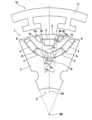
- FIG 1 schematically shows an electric machine 10 according to an embodiment of the invention.
- the electric machine 10 has a stator 11 and a rotor 1.
- the stator 11 serves to drive the Rotor 1.
- the illustration in Figure 1 is only for a single rotor pole 5 of the rotor 1, the remaining arrangement of rotor 1 and/or stator 11 preferably being symmetrical to the section shown.
- the rotor 1 has a rotor body 2, which is designed to be rotatable about a rotation axis 100.
- the rotor body 2 is preferably formed from a plurality of stacked laminations.
- the laminations are, for example, stamped from electrical steel sheet.
- the rotor body 2 has an outer circumference 8 and a plurality of magnetic pockets 6, 7.
- the rotor body 2 also forms a plurality of rotor poles 5, wherein, as previously described, only one of these rotor poles 5 is shown in Figure 1.
- Said rotor pole 5, in turn, has a pole center axis 101, wherein the rotor pole 5 is formed symmetrically to this pole center axis 101.
- Each rotor pole 5 has a multi-layer arrangement of permanent magnets 4, with permanent magnets 4 of a radially inner layer 3i and permanent magnets 4 of a radially outer layer 3a being provided.
- the radially inner layer 3i is arranged at a radial distance from the radially outer layer 3a.
- the radially inner layer 3i has two inner pockets 6 arranged symmetrically to the pole center axis 101.
- An inner web 9i is provided between the two inner pockets 6.
- the inner web 9i is a single web arranged symmetrically to the pole center axis 101.
- the radially outer layer 3a has an outer pocket 7 arranged symmetrically to the pole center axis 101. Furthermore, it is provided that between the outer circumference 8 of the rotor body 2 and the outer pocket 7, two additional pockets 12 acting as a flux barrier and arranged symmetrically to the pole center axis 101 are provided. A first outer web 9a is arranged between each additional pocket 12 and the outer pocket 7. A second outer web 9u is also provided between each additional pocket 12 and the outer circumference 8 of the rotor body 2. Thus, a cross-section of the additional pockets 12 is closed at least with respect to the plane perpendicular to the rotation axis 100.
- additional pockets 12 are also possible, such as, in particular, the design of the additional pockets 12 with an open cross-section, in which the additional pockets 12 are open towards the outer circumference 8.
- the additional pockets 12 is advantageously filled with a magnetically non-conductive material to increase mechanical strength.
- a corresponding filling other than air is not necessary in the embodiment shown in Figure 1; rather, the additional pocket 12 is left free and thus filled only with ambient air. In this case, the effect as a flow barrier is achieved simply and with little effort.
- only one permanent magnet 4 is mounted between the two first outer webs 9a. This applies in particular to the plane perpendicular to the rotation axis 100, since several permanent magnets 4 can advantageously be stacked in the axial direction relative to the rotation axis 100.
- each inner pocket 6 preferably two permanent magnets 4 are arranged between the inner web 9i and the outer circumference 8 of the rotor body 2. This also applies in particular to the plane perpendicular to the rotation axis, since here, too, several permanent magnets 4 can be stacked in the axial direction relative to the rotation axis 100.
- Each inner pocket 6 is preferably angled, so that each permanent magnet 4 of the inner pocket 6 has a different angle to the pole center axis 101.
- the symmetrical design of the two inner pockets 6 of a rotor pole 5 with respect to the pole center axis 101 thus ensures that two permanent magnets 4 of each inner pocket 6 are arranged symmetrically to one another.
- Each of these pairs of symmetrically arranged permanent magnets 4 forms an acute opening angle ⁇ i1 and ⁇ i2 .
- the symmetrically arranged permanent magnets 4 located radially further inside form the acute opening angle ⁇ i2 while the two permanent magnets 4 of the inner pockets 6 located radially further out form the acute opening angle ⁇ i1 .
- the two first outer webs 9a of the radially outer layer 3a also form an acute angle, the acute web angle ⁇ sa .
- each opening angle ⁇ i1 and ⁇ i2 is larger than the web angle ⁇ sa . In this way, the magnetic fluxes within the rotor 1 can be optimized to maximize the performance of the electric machine 10.
- the inner web 9i has a width b si measured in the circumferential direction of the rotor 1.
- the first outer webs 9a have a width b sa measured in the circumferential direction of the rotor 1.
- the width b si of the inner web 9i is larger than the width b sa of the first outer web 9a.
- the previously described design of the radially inner layer 3i and the radially outer layer 3a enables the permanent magnets 4 to be provided in a C-minus arrangement, whereby this arrangement is simple and inexpensive to achieve.
- all permanent magnets 4 provided in the rotor pole 5 have identical dimensions. This simplifies the assembly of the rotor 1, since no assignment of permanent magnets 4 to specific positions needs to be observed.
- the C-minus arrangement enables an optimized rotor flux with increased torque resistance. This, on the one hand, enables high torque and high power.
- the demagnetization resistance of the permanent magnets 4 and thus the rotor limit temperature are increased. This increases the continuous performance of the electric machine 10.
- the simple arrangement described above also minimizes manufacturing costs and material costs.
Landscapes
- Engineering & Computer Science (AREA)
- Power Engineering (AREA)
- Permanent Field Magnets Of Synchronous Machinery (AREA)
- Iron Core Of Rotating Electric Machines (AREA)
Description
- Die vorliegende Erfindung betrifft einen Rotor einer elektrischen Maschine.
- Außerdem betrifft die Erfindung eine elektrische Maschine aufweisend einen derartigen Rotor. Der Rotor weist eine mehrschichtige Anordnung von Permanentmagneten auf.
- Aus dem Stand der Technik sind elektrische Maschinen bekannt. Diese weisen oftmals einen Rotor auf, in dem Permanentmagnete vorgesehen sind. Diese Permanentmagnete lassen sich in unterschiedlichen Anordnungen innerhalb des Rotors bereitstellen. So ist beispielsweise eine mehrschichtige Anordnung von Permanentmagneten in der Art einer Multi-C-Anordnung mit vier Schichten aus der
FR 2 973 179 B1 US 2013/307363 A1 bekannt. -
GB2551537A - Die Aufgabe der Erfindung ist einen Rotor einer elektrischen Maschine bereit zu stellen, der für die elektrische Maschine ein hohes Drehmoment und eine hohe Leistung bei gleichzeitig bestehender hoher Drehzahlfestigkeit und geringer Drehmomentwelligkeit gewährleistet.
- Die erfindungsgemäße Aufgabe wird durch einen Rotor einer elektrischen Maschine gemäß den Merkmalen des unabhängigen Hauptanspruchs 1 gelöst.
- Die Unteransprüche zeigen bevorzugte Weiterbildungen der Erfindung.
- Der erfindungsgemäße Rotor mit den kennzeichnenden Merkmalen des unabhängigen Hauptanspruchs 1 weist eine mehrschichtige Anordnung von Permanentmagneten auf, die eine Steigerung des magnetischen Rotorflusses gegenüber dem Stand der Technik ermöglicht. Gleichzeitig ist die Drehzahlfestigkeit des Rotors erhöht. Weiterhin ermöglicht der Rotor die Reduktion von Magnetverlusten durch Oberschwingungen, wodurch insgesamt die Dauerperformance einer elektrischen Maschine erhöht ist.
- Die mehrschichtige Anordnung der Permanentmagnete ist insbesondere nicht durch lediglich viele kleine Permanentmagnete zu realisieren, sondern ermöglicht die Verwendung von größeren Permanentmagneten verglichen mit dem Stand der Technik. Dies führt zu einer höheren Entmagnetisierungsfestigkeit, wodurch höhere Rotortemperaturen tolerierbar sind, ohne das die Performance der elektrischen Maschine negativ beeinflusst wird.
- Der Rotor weist einen um eine Rotorachse drehbaren Rotorkörper auf. Der Rotorkörper ist insbesondere durch eine Vielzahl von einzelnen Blechlamellen gebildet, die zu einem Lamellenpaket gestapelt sind. Die einzelnen Blechlamellen sind insbesondere aus Elektroblech gefertigt, besonders bevorzugt ausgestanzte. Der Rotorkörper weist einen Außenumfang und mehrere Rotorpole auf, wobei jeder Rotorpol eine Polmittelachse und eine Anordnung von Innentaschen des Rotorkörpers angeordneten Permanentmagneten aufweist. Die Taschen sind somit bevorzugt in dem Stapel der einzelnen Blechlamellen ausgebildet.
- Die Anordnung von Permanentmagneten umfasst zwei in radialer Richtung zueinander beabstandete Schichten mit Permanentmagneten, wobei die radial innere Schicht zwei symmetrisch zur Polmittelachse angeordnete innere Taschen und einen zwischen den beiden inneren Taschen vorgesehen Innensteg aufweist. Die radial äußere Schicht weist eine symmetrisch zur Polmittelachse angeordnete äußere Tasche auf. Die radial äußere Schicht weist somit besonders vorteilhaft eine solche Tasche auf, die tangential zur Polmittelachse ausgebildet ist. Durch eine derartige Anordnung lassen sich insbesondere kritische Ordnungen der Drehmomentwelligkeit signifikant reduzieren.
- Erfindungsgemäß ist der Innensteg ein einziger, symmetrisch zur Polmittelachse angeordneter Steg. Somit erstreckt sich der Innensteg vorteilhafterweise entlang der Polmittelachse und trennt somit die beiden inneren Taschen voneinander. Zwischen dem Außenumfang des Rotorkörpers und der äußeren Tasche sind zwei als Flussbarrieren wirkende Zusatztaschen vorgesehen. Die Zusatztaschen sind ebenfalls symmetrisch zur Polmittelachse angeordnet. Jede Zusatztasche bildet einen ersten Außensteg zwischen der Zusatztasche und der äußeren Tasche. Somit sind zwei erste Außenstege vorhanden, zwischen denen sich die äußere Tasche befindet. Eine solche Anordnung von Taschen und Stegen wird im Folgenden auch C-Minus-Anordnung bezeichnet. Dies folgt insbesondere daraus, dass die Permanentmagnete der radial inneren Schicht C-förmig angeordnet sind, während die radial äußere Schicht insbesondere die Form eines Minus aufweist.
- Der beschriebene Rotor eignet sich insbesondere zum Einsatz in elektrischen Maschinen für Hybridfahrzeuge oder Elektrofahrzeuge und ist insbesondere in permanenterregten Synchronmaschinen einsetzbar. Wird der Rotor in solchen elektrischen Maschinen verwendet, so lassen sich hohe Drehmomente und hohe Leistungen erreichen, wobei gleichzeitig eine hohe Drehzahlfestigkeit vorhanden ist. Die Anordnung ermöglicht weiterhin eine hohe Entmagnetisierungsfestigkeit der verwendeten Permanentmagnete, wodurch eine Rotorgrenztemperatur erhöht ist. Dies führt insbesondere zu besagter hoher Dauerperformance der elektrischen Maschine. Weiterhin ermöglicht die Anordnung der Permanentmagneten, insbesondere die Anordnung in der radial äußeren Schicht, eine geringe Drehmomentenwelligkeit. Weitere Vorteile der genannten Anordnung sind niedrige Verluste, insbesondere niedrige Eisenverluste und Magnetverluste sowie niedrige Materialkosten und Herstellungskosten.
- Besonders bevorzugt ist vorgesehen, dass jede Zusatztasche zusätzlich einen zweiten Außensteg zwischen dem Außenumfang des Rotorkörpers und der Zusatztasche bildet. Somit ist die Zusatztasche durch den ersten Außensteg und den zweiten Außensteg begrenzt und weist somit zumindest in der Ebene senkrecht zur Rotationsachse einen geschlossenen Querschnitt auf. Die Zusatztasche bleibt vorteilhafterweise leer und ist somit lediglich mit Umgebungsluft gefüllt. Auf diese Weise wirkt die Zusatztasche als Flussbarriere, während die zweiten Außenstege eine hohe Drehmomentfestigkeit des Rotors sicherstellen.
- In einer alternativen, nicht dargestellten Ausgestaltung ist bevorzugt vorgesehen, dass die Zusatztaschen im Stapel von Blechlamellen zum Außenumfang hin offen ausgebildet sind. Somit sind die zuvor beschriebenen zweiten Außenstege insbesondere nicht vorhanden. Die Zusatztaschen sind in diesem Fall vorteilhafterweise mit einer magnetisch nicht leitfähigen Masse aufgefüllt. Durch die magnetisch nicht leitfähige Masse ist insbesondere eine mechanische Stabilität des Rotors erhöht, wodurch die entsprechende Zusatztasche einerseits als Flussbarriere wirkt, andererseits die Drehzahlfestigkeit des Rotors sicherstellt.
- Vorteilhafterweise ist in jeder inneren Tasche und/oder in jeder äußeren Tasche in axialer Richtung eine Vielzahl von Permanentmagneten hintereinander angeordnet. Somit ist die axiale Abmessung jedes Permanentmagnets nicht zwingend identisch zur axialen Abmessung des Rotorkörpers. Vielmehr lassen sich in axialer Richtung mehrere Permanentmagnete hintereinander anordnen, um die inneren Taschen und/oder äußeren Taschen aufzufüllen.
- Erfindungsgemäß ist vorgesehen, dass jeweils zwei Permanentmagnete der radial inneren Schicht bezüglich der Polmittelachse symmetrisch angeordnet sind und jeweils einen spitzen Öffnungswinkel αi1, αi2 zueinander einschließen. Dies bedeutet, dass die Permanentmagnete zueinander einen Winkel einnehmen, der kleiner als 180° ist. Die beiden ersten Außenstege der radial äußeren Schicht schließen einen spitzen Stegwinkel βsa zueinander ein. Erfindungsgemäß ist ferner vorgesehen, dass der Öffnungswinkel αi1, αi2 jedes Paares von symmetrisch angeordneten Permanentmagneten der radial inneren Schicht größer ist als der Stegwinkel βsa zwischen den ersten Außenstegen. Dies führt insbesondere zu einem optimierten Magnetfluss innerhalb des Rotors, wodurch sich hohe Leistungen der den Rotor verwendenden elektrischen Maschine bei gleichzeitig hoher Drehmomentfestigkeit erreichen lassen.
- Vorteilhafterweise ist außerdem vorgesehen, dass der Innensteg jedes Rotorpols eine in Umfangsrichtung des Rotors gemessene Breite bsi aufweist. Die ersten Außenstege jedes Rotorpols weisen eine Umfangsrichtung des Rotors gemessene Breite bsa auf. Es ist vorteilhafterweise vorgesehen, dass die Breite bsi des Innenstegs größer ausgebildet ist, als die Breite bsa der ersten Außenstege. Somit erfolgt eine optimale Auslegung der jeweiligen Stege in Abhängigkeit der zu tragenden Kräfte sowie optimiert für einen maximalen magnetischen Rotorflusspunkt insbesondere lassen sich Streuflüsse minimieren.
- Zwischen den ersten Außenstegen jeder äußeren Tasche ist bevorzugt ein einziger Permanentmagnet angeordnet. Dies gilt insbesondere innerhalb der Ebene senkrecht zur Rotationsachse, sodass weiterhin möglich ist, mehrere Permanentmagnete in axialer Richtung zu stapeln.
- In jeder der beiden inneren Taschen sind bevorzugt jeweils zwischen dem Innensteg und dem Außenumfang des Rotorkörpers zumindest zwei nebeneinanderliegende Permanentmagnete angeordnet. Dies gilt wiederrum bevorzugt in der Ebene senkrecht zur Rotationsachse, sodass weiterhin ermöglicht ist, mehrere Permanentmagnete axial zu stapeln. Die beiden Permanentmagnete pro innere Tasche sind insbesondere derart angeordnet, dass diese den Permanentmagneten in der äußeren Tasche zumindest teilweise umgreifen. Somit ist insbesondere die zuvor beschriebene C-Minus-Anordnung auf einfache Art erreicht.
- Die beiden inneren Taschen sind bevorzugt jeweils derart abgeknickt ausgebildet, dass die Permanentmagnete jeder inneren Tasche unterschiedliche Winkel zur Polmittelachse aufweisen. Auf diese Weise ist insbesondere die zuvor beschriebene C-Form realisiert. Die Anordnung der Permanentmagnete und die Montage des Rotors ist somit vereinfacht.
- Bevorzugt weisen die Magnete jedes Rotorpols insbesondere die Magnete des gesamten Rotors, identische Abmessungen auf. Somit ist die Bereitstellung der Permanentmagnete einfach und aufwandsarm ermöglicht. Außerdem ist die Montage des Rotors vereinfacht, da in jeder zur Montage von Magneten vorgesehen Position ein identischer Permanentmagnet verwendet werden kann.
- Die Erfindung betrifft außerdem eine elektrische Maschine nach Anspruch 9. Die elektrische Maschine weist einen Rotor wie zuvor beschrieben auf. Außerdem weist die elektrische Maschine einen Stator zum Antreiben des Rotors auf. Die Verwendung des Rotors wie zuvor beschrieben führt insbesondere zu den zuvor genannten vorteilhaften Eigenschaften der elektrischen Maschine.
- Nachfolgend werden Ausführungsbeispiele der Erfindung unter Bezugnahme auf die begleitende Zeichnung im Detail beschrieben. In der Zeichnung ist:
- Figur 1
- schematische Abbildung einer elektrischen Maschine gemäß einem Ausführungsbeispiel der Erfindung
- Die Figur 1 zeigt schematisch eine elektrische Maschine 10 gemäß einem Ausführungsbeispiel der Erfindung. Die elektrische Maschine 10 weist einen Stator 11 sowie einen Rotor 1 auf. Der Stator 11 dient zum Antreiben des Rotors 1. Die Darstellung in Figur 1 erfolgt lediglich für einen einzelnen Rotorpol 5 des Rotors 1, wobei die restliche Anordnung von Rotor 1 und/oder Stator 11 bevorzugt symmetrisch zu dem gezeigten Ausschnitt ist.
- Der Rotor 1 weist einen Rotorkörper 2 auf, der um eine Rotationsachse 100 rotierbar ausgebildet ist. Der Rotorkörper 2 ist bevorzugt aus einer Vielzahl von gestapelten Blechlamellen gebildet. Die Blechlamellen sind beispielsweise aus Elektroblech gestanzt.
- Der Rotorkörper 2 weist einen Außenumfang 8 sowie eine Vielzahl von Magnettaschen 6, 7 auf. Der Rotorkörper 2 bildet außerdem mehrere Rotorpole 5, wobei, wie zuvor beschrieben, in Figur 1 lediglich einer dieser Rotorpole 5 gezeigt ist. Besagter Rotorpol 5 wiederum weist eine Polmittelachse 101 auf, wobei der Rotorpol 5 symmetrisch zu dieser Polmittelachse 101 ausgebildet ist.
- Jeder Rotorpol 5 weist eine mehrschichtige Anordnung von Permanentmagneten 4 auf, wobei einerseits Permanentmagnete 4 einer radial inneren Schicht 3i und Permanentmagnete 4 einer radial äußeren Schicht 3a vorgesehen sind. Die radial innere Schicht 3i ist von der radial äußeren Schicht 3a in Radialrichtung beabstandet angeordnet. Die radial innere Schicht 3i weist zwei symmetrisch zur Polmittelachse 101 angeordnete innere Taschen 6 auf. Zwischen den beiden inneren Taschen 6 ist ein Innensteg 9i vorgesehen. Der Innensteg 9i ist ein einziger, symmetrisch zur Polmittelachse 101 angeordneter Steg.
- Die radial äußere Schicht 3a weist eine symmetrisch zur Polmittelachse 101 angeordnete äußere Tasche 7 auf. Außerdem ist vorgesehen, dass zwischen dem Außenumfang 8 des Rotorkörpers 2 und der äußeren Tasche 7 zwei als Flussbarriere wirkende, symmetrisch zur Polmittelachse 101 angeordnet Zusatztaschen 12 vorgesehen sind. Zwischen der Zusatztasche 12 und der äußeren Tasche 7 ist jeweils ein erster Außensteg 9a angeordnet. Zwischen jeder Zusatztasche 12 und dem Außenumfang 8 des Rotorkörpers 2 ist außerdem jeweils ein zweiter Außensteg 9u vorgesehen. Somit ist ein Querschnitt der Zusatztaschen 12 zumindest bezüglich der Ebene senkrecht zur Rotationsachse 100 geschlossen ausgebildet. Es sind aber auch alternative, nicht dargestellte Ausgestaltungen möglich, wie insbesondere die Ausbildung der Zusatztaschen 12 mit offenem Querschnitt, bei der die Zusatztaschen 12 zum Außenumfang 8 hin offen ausgebildet sind. In diesem Fall sind die Zusatztaschen 12 zur Erhöhung der mechanischen Festigkeit vorteilhafterweise mit einem magnetisch nicht leitfähigem Material gefüllt. Eine entsprechende Füllung abgesehen von Luft ist in der Figur 1 gezeigten Ausgestaltung nicht notwendig, vielmehr ist hier vorgesehen, dass die Zusatztasche 12 frei bleibt und somit lediglich mit Umgebungslust aufgefüllt ist. In diesem Fall ist die Wirkung als Flussbarriere einfach und aufwandsarm erreicht.
- In der äußeren Tasche 7 ist zwischen den beiden ersten Außenstegen 9a lediglich ein Permanentmagnet 4 angebracht. Dies bezieht sich insbesondere auf die Ebene senkrecht zur Rotationsachse 100, da vorteilhafterweise in axialer Richtung bezüglich der Rotationsachse 100 mehrere Permanentmagnete 4 gestapelt werden können.
- In jeder inneren Tasche 6 sind zwischen Innensteg 9i und dem Außenumfang 8 des Rotorkörpers 2 bevorzugt jeweils zwei Permanentmagnete 4 angeordnet. Auch dies bezieht sich insbesondere auf die Ebene senkrecht zur Rotationsachse, da auch hier in axialer Richtung bezüglich der Rotationsachse 100 mehrere Permanentmagnete 4 gestapelt werden können.
- Jede innere Tasche 6 ist bevorzugt abgewinkelt ausgebildet, sodass jeder Permanentmagnet 4 der inneren Tasche 6 einen anderen Winkel zur Polmittelachse 101 aufweist. Durch die symmetrische Ausgestaltung der beiden inneren Taschen 6 eines Rotorpols 5 bezüglich der Polmittelachse 101 ist somit erreicht, dass jeweils zwei Permanentmagnete 4 jeder inneren Tasche 6 symmetrisch zueinander angeordnet sind. Jedes dieser Paare von symmetrisch angeordneten Permanentmagneten 4 bildet einen spitzen Öffnungswinkel αi1 und αi2. In Figur 1 bilden die radial weiter innen gelegenen symmetrisch angeordneten Permanentmagnete 4 den spitzen Öffnungswinkel αi2 während die beiden radial weiter außen gelegenen Permanentmagnete 4 der inneren Taschen 6 den spitzen Öffnungswinkel αi1 bilden. Auch die beiden ersten Außenstege 9a der radial äußeren Schicht 3a bilden einen spitzen Winkel, den spitzen Stegwinkel βsa.
- Es ist vorgesehen, dass jeder Öffnungswinkel αi1 und αi2 größer ist als der Stegwinkel βsa. Auf diese Weise lassen sich die magnetischen Flüsse innerhalb des Rotors 1 optimieren, um eine Performance der elektrischen Maschine 10 zu maximieren.
- Des Weiteren ist vorgesehen, dass der Innensteg 9i eine in Umfangsrichtung des Rotors 1 gemessene Breite bsi aufweist. Die ersten Außenstege 9a weisen eine in Umfangsrichtung des Rotors 1 gemessene Breite bsa auf. Hier ist vorgesehen, dass die Breite bsi des Innenstegs 9i größer ausgebildet ist als die Breite bsa der ersten Außensteges 9a. Somit sind die Größen der entsprechenden Stege 9i, 9a hinsichtlich vorhandener Kraftverhältnisse optimiert, wobei die Ausbildung von Streuflüssen minimiert ist.
- Die zuvor beschriebene Ausbildung der radial inneren Schicht 3i und der radial äußeren Schicht 3a ermöglicht die Bereitstellung der Permanentmagnete 4 in einer C-Minus-Anordnung, wobei diese Anordnung einfach und aufwandsarm erreichbar ist. So ist insbesondere vorgesehen, dass sämtliche im Rotorpol 5 vorgesehen Permanentmagnete 4 identische Abmessungen aufweisen. Dies vereinfacht die Montage des Rotors 1, da keinerlei Zuordnungen von Permanentmagneten 4 zu bestimmten Positionen zu beachten sind. Gleichzeitig ermöglicht die C-Minus-Anordnung einen optimierten Rotorfluss bei erhöhter Drehmomentfestigkeit. Somit ist einerseits ein hohes Drehmoment und eine hohe Leistung ermöglicht. Andererseits sind aufgrund der Möglichkeit größere Permanentmagnete 4 zu verwenden, eine Entmagnetisierungsfestigkeit der Permanentmagnete 4 und damit eine Rotorgrenztemperatur erhöht. Somit ist eine Dauerperformance der elektrischen Maschine 10 erhöht. Durch die zuvor beschrieben einfache Anordnung lassen sich außerdem Herstellungskosten und Materialkosten minimieren.
Claims (9)
- Rotor (1) einer elektrischen Maschine (10), umfassend einen um eine Rotorachse (100) rotierbaren Rotorkörper (2), der einen Außenumfang (8) und mehrere Rotorpole (5) aufweist und durch einen Stapel von Blechlamellen gebildet ist, wobei jeder Rotorpol (5) eine Polmittelachse (101) und eine Anordnung von in Taschen (6, 7) des Rotorkörpers (2), insbesondere des Stapels von Blechlamellen, angeordneten Permanentmagneten (4) aufweist, wobei die Anordnung von Permanentmagneten (4) zwei in radialer Richtung zueinander beanstandete Schichten (3i, 3a) mit Permanentmagneten (4) umfasst, wobei die radial innere Schicht (3i) zwei symmetrisch zur Polmittelachse (101) angeordnete innere Taschen (6) und einen zwischen den beiden inneren Taschen (6) liegenden Innensteg (9i) aufweist, wobei die radial äußere Schicht (3a) eine symmetrisch zur Polmittelachse (101) angeordnete äußere Tasche (7) aufweist,wobei der Innensteg (9i) ein einziger, symmetrisch zur Polmittelachse (101) angeordneter Steg ist, wobeizwischen dem Außenumfang (8) des Rotorkörpers (2) und der äußeren Tasche (7) zwei als Flussbarriere wirkende, symmetrisch zur Polmittelachse (101) angeordnete Zusatztaschen (12) vorgesehen sind, wobeijede Zusatztasche (12) einen ersten Außensteg (9a) zwischen der Zusatztasche (12) und der äußeren Tasche (7) bildet,wobei jeweils zwei Permanentmagnete (4) der radial inneren Schicht (3i) bezüglich der Polmittelachse (101) symmetrisch angeordnet sind und jeweils einen spitzen Öffnungswinkel αi1, αi2 einschließen, wobei die beiden ersten Außenstege (9a) der radial äußeren Schicht (3a) einen spitzen Stegwinkel βsa einschließen,dadurch gekennzeichnet, dassin jeder der beiden inneren Taschen (6) jeweils zwischen dem Innensteg (9i) und dem Außenumfang (8) des Rotorkörpers (2) zumindest zwei nebeneinander liegende Permanentmagnete (4) angeordnet sind, dassder Öffnungswinkel αi1, αi2 jedes Paares von symmetrisch angeordneten Permanentmagneten (4) der radial inneren Schicht (3i) größer ist als der Stegwinkel βsa zwischen den ersten Außenstegen (9a), und dassder spitze Stegwinkel βsa zum Außenumfang (8) des Rotorkörpers (2) hin geöffnet ist.
- Rotor nach Anspruch 1, dadurch gekennzeichnet, dass jede Zusatztasche (12) zusätzlich einen zweiten Außensteg (9u) zwischen dem Außenumfang (8) des Rotorkörpers (2) und der Zusatztasche (12) bildet.
- Rotor nach Anspruch 1, dadurch gekennzeichnet, dass die Zusatztaschen (12) im Stapel von Blechlamellen zum Außenumfang (8) hin offen ausgebildet und mit einer magnetisch nicht leitfähigen Masse ausgefüllt sind.
- Rotor nach einem der vorhergehenden Ansprüche, dadurch gekennzeichnet, dass in jeder inneren Tasche (6) und/oder äußeren Tasche (7) in axialer Richtung bezüglich der Rotorachse mehrere Permanentmagnete (4) hintereinander angeordnet sind.
- Rotor (1) nach einem der vorhergehenden Ansprüche, dadurch gekennzeichnet, dass der Innensteg (9i) jedes Rotorpols (5) eine in Umfangsrichtung des Rotors (1) gemessene Breite bsi und die ersten Außenstege (9a) jedes Rotorpols (5) eine in Umfangsrichtung des Rotors (1) gemessene Breite bsa aufweisen, wobei die Breite bsi des Innenstegs (9i) größer ausgebildet ist als die Breite bsa der ersten Außenstege (9a).
- Rotor (1) nach einem der vorhergehenden Ansprüche, dadurch gekennzeichnet, dass zwischen den ersten Außenstegen (9a) jeder äußeren Tasche (7) ein einziger Permanentmagnet (4) angeordnet ist.
- Rotor (1) nach einem der vorhergehenden Ansprüche, dadurch gekennzeichnet, dass die beiden inneren Taschen (6) jeweils derart abgeknickt ausgebildet sind, dass die Permanentmagnete (4) jeder inneren Tasche (6) unterschiedliche Winkel zu der Polmittelachse (101) aufweisen.
- Rotor (1) nach einem der vorhergehenden Ansprüche, dadurch gekennzeichnet, dass die Permanentmagnete (4) jedes Rotorpols (5) identische Abmessungen aufweisen.
- Elektrische Maschine (10) aufweisend einen Rotor (1) nach einem der vorhergehenden Ansprüche sowie einen Stator (11) zum Antreiben des Rotors (1).
Applications Claiming Priority (2)
| Application Number | Priority Date | Filing Date | Title |
|---|---|---|---|
| DE102020214035.9A DE102020214035A1 (de) | 2020-11-09 | 2020-11-09 | Rotor einer elektrischen Maschine mit mehrschichtiger Permanentmagnetanordnung |
| PCT/EP2021/079484 WO2022096300A1 (de) | 2020-11-09 | 2021-10-25 | Rotor einer elektrischen maschine mit mehrschichtiger permanentmagnetanordnung |
Publications (2)
| Publication Number | Publication Date |
|---|---|
| EP4241367A1 EP4241367A1 (de) | 2023-09-13 |
| EP4241367B1 true EP4241367B1 (de) | 2025-05-28 |
Family
ID=78414029
Family Applications (1)
| Application Number | Title | Priority Date | Filing Date |
|---|---|---|---|
| EP21799026.6A Active EP4241367B1 (de) | 2020-11-09 | 2021-10-25 | Rotor einer elektrischen maschine mit mehrschichtiger permanentmagnetanordnung |
Country Status (5)
| Country | Link |
|---|---|
| US (1) | US12407202B2 (de) |
| EP (1) | EP4241367B1 (de) |
| CN (1) | CN116368713A (de) |
| DE (1) | DE102020214035A1 (de) |
| WO (1) | WO2022096300A1 (de) |
Families Citing this family (3)
| Publication number | Priority date | Publication date | Assignee | Title |
|---|---|---|---|---|
| DE102022125974A1 (de) * | 2022-10-07 | 2024-04-18 | Dr. Ing. H.C. F. Porsche Aktiengesellschaft | Rotor einer Elektromaschine |
| DE102023205769A1 (de) * | 2023-06-20 | 2024-07-11 | Magna powertrain gmbh & co kg | Rotor einer permanentmagneterregten elektrischen Maschine |
| FR3166768A1 (fr) * | 2024-09-24 | 2026-03-27 | Valeo Eautomotive Germany Gmbh | Machine électrique à aimants permanents |
Family Cites Families (9)
| Publication number | Priority date | Publication date | Assignee | Title |
|---|---|---|---|---|
| JP5643127B2 (ja) | 2011-02-03 | 2014-12-17 | トヨタ自動車株式会社 | 回転電機用回転子 |
| FR2973179B1 (fr) | 2011-03-21 | 2014-09-05 | Renault Sa | Machine electrique a ondulation de couple reduite |
| JP5737250B2 (ja) * | 2012-09-21 | 2015-06-17 | 株式会社デンソー | ロータおよび回転電機 |
| GB201510273D0 (en) * | 2015-06-12 | 2015-07-29 | Jaguar Land Rover Ltd | Electric drive motor |
| EP3128647B1 (de) * | 2015-08-05 | 2018-06-06 | ABB Schweiz AG | Rotor für eine elektrische drehmaschine |
| GB2551537A (en) * | 2016-06-21 | 2017-12-27 | Jaguar Land Rover Ltd | Electrical machine |
| DE102017209247A1 (de) * | 2017-05-31 | 2018-12-06 | Volkswagen Aktiengesellschaft | Blechschnitt für einen Rotor einer elektrischen Maschine, Rotor für eine elektrische Maschine und elektrische Maschine mit Rotor |
| JP6879140B2 (ja) * | 2017-09-15 | 2021-06-02 | トヨタ自動車株式会社 | 回転電機 |
| DE102018128146A1 (de) * | 2018-11-09 | 2020-05-14 | Brusa Elektronik Ag | Rotor für einen Synchron-Antriebsmotor |
-
2020
- 2020-11-09 DE DE102020214035.9A patent/DE102020214035A1/de active Pending
-
2021
- 2021-10-25 US US18/251,473 patent/US12407202B2/en active Active
- 2021-10-25 WO PCT/EP2021/079484 patent/WO2022096300A1/de not_active Ceased
- 2021-10-25 CN CN202180074352.XA patent/CN116368713A/zh active Pending
- 2021-10-25 EP EP21799026.6A patent/EP4241367B1/de active Active
Also Published As
| Publication number | Publication date |
|---|---|
| WO2022096300A1 (de) | 2022-05-12 |
| US20230412020A1 (en) | 2023-12-21 |
| EP4241367A1 (de) | 2023-09-13 |
| CN116368713A (zh) | 2023-06-30 |
| DE102020214035A1 (de) | 2022-05-12 |
| US12407202B2 (en) | 2025-09-02 |
Similar Documents
| Publication | Publication Date | Title |
|---|---|---|
| EP2073352B1 (de) | Permanenterregte Synchronmaschine mit Schalenmagneten | |
| EP3084936B1 (de) | Reluktanzrotor aufweisend ein reluktanzrotorblech mit aussparung zur spannungsreduktion | |
| DE102010032764A1 (de) | Elektrische Maschine und Stator für dieselbe | |
| WO2020057847A1 (de) | Rotor mit eingebetteten magneten | |
| EP4241367A1 (de) | Rotor einer elektrischen maschine mit mehrschichtiger permanentmagnetanordnung | |
| DE102017209247A1 (de) | Blechschnitt für einen Rotor einer elektrischen Maschine, Rotor für eine elektrische Maschine und elektrische Maschine mit Rotor | |
| EP3949083B1 (de) | Vierpoliger synchron-reluktanzmotor | |
| DE102011083577A1 (de) | Elektrische Maschine mit Stator mit variablem Nutabstand | |
| DE112020000164T5 (de) | Elektrische Maschine mit innenliegenden Permanentmagneten und flussverteilenden Hohlräumen | |
| DE102017101913A1 (de) | Elektromotor mit eingebettetem Dauermagnet | |
| DE102013202006B4 (de) | Läuferanordnung für eine permanentmagneterregte elektrische Maschine | |
| EP3829031B1 (de) | Rotorblech, rotorblechpaket, rotor, elektrische maschine und fahrzeug | |
| DE102020212636A1 (de) | Rotor für eine elektrische Maschine, elektrische Maschine und Kraftfahrzeug | |
| WO2018115074A1 (de) | Elektromotor mit niedrigem nutrastmoment | |
| EP2705590B1 (de) | Rotor für eine permanentmagnetische maschine | |
| DE102020113938A1 (de) | Blechpaket für eine permanenterregte Synchronmaschine mit vergrößerten Magnettaschen zum Erhöhen eines Drehmoments durch Reluktanz sowie Synchronmaschine und Kraftfahrzeug | |
| WO2020221543A1 (de) | Rotor einer elektrischen maschine | |
| DE102015222271A1 (de) | Rotor sowie elektrische Maschine | |
| EP3900156B1 (de) | Blechpaket für eine elektrische maschine | |
| DE102023201638A1 (de) | Rotor, Asynchronmaschine und Kraftfahrzeug | |
| EP4612778B1 (de) | Segmentierungsanordnung für permanentmagnete einer doppel-v-anordnung in einem rotor für eine permanenterregte elektrische maschine | |
| DE102019005465A1 (de) | Elektrische rotationsmaschine, ausgestattet mit einem rotor verringerter masse | |
| EP4305736B1 (de) | Rotor einer elektrischen maschine | |
| WO2011026600A2 (de) | Elektrische maschine und verfahren zu deren herstellung | |
| EP3618232A1 (de) | Elektrische maschine, verfahren zur herstellung einer elektrischen maschine und elektrisches fahrzeug |
Legal Events
| Date | Code | Title | Description |
|---|---|---|---|
| STAA | Information on the status of an ep patent application or granted ep patent |
Free format text: STATUS: UNKNOWN |
|
| STAA | Information on the status of an ep patent application or granted ep patent |
Free format text: STATUS: THE INTERNATIONAL PUBLICATION HAS BEEN MADE |
|
| PUAI | Public reference made under article 153(3) epc to a published international application that has entered the european phase |
Free format text: ORIGINAL CODE: 0009012 |
|
| STAA | Information on the status of an ep patent application or granted ep patent |
Free format text: STATUS: REQUEST FOR EXAMINATION WAS MADE |
|
| 17P | Request for examination filed |
Effective date: 20230609 |
|
| AK | Designated contracting states |
Kind code of ref document: A1 Designated state(s): AL AT BE BG CH CY CZ DE DK EE ES FI FR GB GR HR HU IE IS IT LI LT LU LV MC MK MT NL NO PL PT RO RS SE SI SK SM TR |
|
| DAV | Request for validation of the european patent (deleted) | ||
| DAX | Request for extension of the european patent (deleted) | ||
| GRAP | Despatch of communication of intention to grant a patent |
Free format text: ORIGINAL CODE: EPIDOSNIGR1 |
|
| STAA | Information on the status of an ep patent application or granted ep patent |
Free format text: STATUS: GRANT OF PATENT IS INTENDED |
|
| INTG | Intention to grant announced |
Effective date: 20250220 |
|
| GRAS | Grant fee paid |
Free format text: ORIGINAL CODE: EPIDOSNIGR3 |
|
| GRAA | (expected) grant |
Free format text: ORIGINAL CODE: 0009210 |
|
| STAA | Information on the status of an ep patent application or granted ep patent |
Free format text: STATUS: THE PATENT HAS BEEN GRANTED |
|
| AK | Designated contracting states |
Kind code of ref document: B1 Designated state(s): AL AT BE BG CH CY CZ DE DK EE ES FI FR GB GR HR HU IE IS IT LI LT LU LV MC MK MT NL NO PL PT RO RS SE SI SK SM TR |
|
| REG | Reference to a national code |
Ref country code: GB Ref legal event code: FG4D Free format text: NOT ENGLISH |
|
| REG | Reference to a national code |
Ref country code: CH Ref legal event code: EP |
|
| REG | Reference to a national code |
Ref country code: DE Ref legal event code: R096 Ref document number: 502021007609 Country of ref document: DE |
|
| REG | Reference to a national code |
Ref country code: IE Ref legal event code: FG4D Free format text: LANGUAGE OF EP DOCUMENT: GERMAN |
|
| REG | Reference to a national code |
Ref country code: NL Ref legal event code: MP Effective date: 20250528 |
|
| PG25 | Lapsed in a contracting state [announced via postgrant information from national office to epo] |
Ref country code: ES Free format text: LAPSE BECAUSE OF FAILURE TO SUBMIT A TRANSLATION OF THE DESCRIPTION OR TO PAY THE FEE WITHIN THE PRESCRIBED TIME-LIMIT Effective date: 20250528 Ref country code: FI Free format text: LAPSE BECAUSE OF FAILURE TO SUBMIT A TRANSLATION OF THE DESCRIPTION OR TO PAY THE FEE WITHIN THE PRESCRIBED TIME-LIMIT Effective date: 20250528 |
|
| REG | Reference to a national code |
Ref country code: LT Ref legal event code: MG9D |
|
| PG25 | Lapsed in a contracting state [announced via postgrant information from national office to epo] |
Ref country code: GR Free format text: LAPSE BECAUSE OF FAILURE TO SUBMIT A TRANSLATION OF THE DESCRIPTION OR TO PAY THE FEE WITHIN THE PRESCRIBED TIME-LIMIT Effective date: 20250829 Ref country code: NO Free format text: LAPSE BECAUSE OF FAILURE TO SUBMIT A TRANSLATION OF THE DESCRIPTION OR TO PAY THE FEE WITHIN THE PRESCRIBED TIME-LIMIT Effective date: 20250828 |
|
| PG25 | Lapsed in a contracting state [announced via postgrant information from national office to epo] |
Ref country code: NL Free format text: LAPSE BECAUSE OF FAILURE TO SUBMIT A TRANSLATION OF THE DESCRIPTION OR TO PAY THE FEE WITHIN THE PRESCRIBED TIME-LIMIT Effective date: 20250528 Ref country code: PL Free format text: LAPSE BECAUSE OF FAILURE TO SUBMIT A TRANSLATION OF THE DESCRIPTION OR TO PAY THE FEE WITHIN THE PRESCRIBED TIME-LIMIT Effective date: 20250528 |
|
| PG25 | Lapsed in a contracting state [announced via postgrant information from national office to epo] |
Ref country code: BG Free format text: LAPSE BECAUSE OF FAILURE TO SUBMIT A TRANSLATION OF THE DESCRIPTION OR TO PAY THE FEE WITHIN THE PRESCRIBED TIME-LIMIT Effective date: 20250528 |
|
| PG25 | Lapsed in a contracting state [announced via postgrant information from national office to epo] |
Ref country code: HR Free format text: LAPSE BECAUSE OF FAILURE TO SUBMIT A TRANSLATION OF THE DESCRIPTION OR TO PAY THE FEE WITHIN THE PRESCRIBED TIME-LIMIT Effective date: 20250528 |
|
| PG25 | Lapsed in a contracting state [announced via postgrant information from national office to epo] |
Ref country code: RS Free format text: LAPSE BECAUSE OF FAILURE TO SUBMIT A TRANSLATION OF THE DESCRIPTION OR TO PAY THE FEE WITHIN THE PRESCRIBED TIME-LIMIT Effective date: 20250828 |
|
| PG25 | Lapsed in a contracting state [announced via postgrant information from national office to epo] |
Ref country code: IS Free format text: LAPSE BECAUSE OF FAILURE TO SUBMIT A TRANSLATION OF THE DESCRIPTION OR TO PAY THE FEE WITHIN THE PRESCRIBED TIME-LIMIT Effective date: 20250928 |
|
| PG25 | Lapsed in a contracting state [announced via postgrant information from national office to epo] |
Ref country code: LV Free format text: LAPSE BECAUSE OF FAILURE TO SUBMIT A TRANSLATION OF THE DESCRIPTION OR TO PAY THE FEE WITHIN THE PRESCRIBED TIME-LIMIT Effective date: 20250528 |
|
| PGFP | Annual fee paid to national office [announced via postgrant information from national office to epo] |
Ref country code: DE Payment date: 20251209 Year of fee payment: 5 |
|
| PGFP | Annual fee paid to national office [announced via postgrant information from national office to epo] |
Ref country code: GB Payment date: 20251024 Year of fee payment: 5 |
|
| PG25 | Lapsed in a contracting state [announced via postgrant information from national office to epo] |
Ref country code: DK Free format text: LAPSE BECAUSE OF FAILURE TO SUBMIT A TRANSLATION OF THE DESCRIPTION OR TO PAY THE FEE WITHIN THE PRESCRIBED TIME-LIMIT Effective date: 20250528 Ref country code: SM Free format text: LAPSE BECAUSE OF FAILURE TO SUBMIT A TRANSLATION OF THE DESCRIPTION OR TO PAY THE FEE WITHIN THE PRESCRIBED TIME-LIMIT Effective date: 20250528 |
|
| PGFP | Annual fee paid to national office [announced via postgrant information from national office to epo] |
Ref country code: AT Payment date: 20260113 Year of fee payment: 5 |
|
| PGFP | Annual fee paid to national office [announced via postgrant information from national office to epo] |
Ref country code: IT Payment date: 20251031 Year of fee payment: 5 |
|
| PGFP | Annual fee paid to national office [announced via postgrant information from national office to epo] |
Ref country code: FR Payment date: 20251027 Year of fee payment: 5 |
|
| PG25 | Lapsed in a contracting state [announced via postgrant information from national office to epo] |
Ref country code: CZ Free format text: LAPSE BECAUSE OF FAILURE TO SUBMIT A TRANSLATION OF THE DESCRIPTION OR TO PAY THE FEE WITHIN THE PRESCRIBED TIME-LIMIT Effective date: 20250528 |
|
| PG25 | Lapsed in a contracting state [announced via postgrant information from national office to epo] |
Ref country code: EE Free format text: LAPSE BECAUSE OF FAILURE TO SUBMIT A TRANSLATION OF THE DESCRIPTION OR TO PAY THE FEE WITHIN THE PRESCRIBED TIME-LIMIT Effective date: 20250528 |
|
| PG25 | Lapsed in a contracting state [announced via postgrant information from national office to epo] |
Ref country code: SK Free format text: LAPSE BECAUSE OF FAILURE TO SUBMIT A TRANSLATION OF THE DESCRIPTION OR TO PAY THE FEE WITHIN THE PRESCRIBED TIME-LIMIT Effective date: 20250528 |
|
| REG | Reference to a national code |
Ref country code: DE Ref legal event code: R097 Ref document number: 502021007609 Country of ref document: DE |
|
| PG25 | Lapsed in a contracting state [announced via postgrant information from national office to epo] |
Ref country code: RO Free format text: LAPSE BECAUSE OF FAILURE TO SUBMIT A TRANSLATION OF THE DESCRIPTION OR TO PAY THE FEE WITHIN THE PRESCRIBED TIME-LIMIT Effective date: 20250528 |
|
| PLBE | No opposition filed within time limit |
Free format text: ORIGINAL CODE: 0009261 |
|
| STAA | Information on the status of an ep patent application or granted ep patent |
Free format text: STATUS: NO OPPOSITION FILED WITHIN TIME LIMIT |
|
| REG | Reference to a national code |
Ref country code: CH Ref legal event code: L10 Free format text: ST27 STATUS EVENT CODE: U-0-0-L10-L00 (AS PROVIDED BY THE NATIONAL OFFICE) Effective date: 20260409 |
|
| 26N | No opposition filed |
Effective date: 20260303 |