EP4240982B1 - Verbesserungen an oder im zusammenhang mit wagen und klemmvorrichtungen - Google Patents
Verbesserungen an oder im zusammenhang mit wagen und klemmvorrichtungen Download PDFInfo
- Publication number
- EP4240982B1 EP4240982B1 EP21819573.3A EP21819573A EP4240982B1 EP 4240982 B1 EP4240982 B1 EP 4240982B1 EP 21819573 A EP21819573 A EP 21819573A EP 4240982 B1 EP4240982 B1 EP 4240982B1
- Authority
- EP
- European Patent Office
- Prior art keywords
- clamping
- holding
- clamping device
- carriage
- passage
- Prior art date
- Legal status (The legal status is an assumption and is not a legal conclusion. Google has not performed a legal analysis and makes no representation as to the accuracy of the status listed.)
- Active
Links
Images



Classifications
-
- B—PERFORMING OPERATIONS; TRANSPORTING
- B25—HAND TOOLS; PORTABLE POWER-DRIVEN TOOLS; MANIPULATORS
- B25B—TOOLS OR BENCH DEVICES NOT OTHERWISE PROVIDED FOR, FOR FASTENING, CONNECTING, DISENGAGING, OR HOLDING
- B25B5/00—Clamps
- B25B5/14—Clamps for work of special profile
-
- F—MECHANICAL ENGINEERING; LIGHTING; HEATING; WEAPONS; BLASTING
- F16—ENGINEERING ELEMENTS AND UNITS; GENERAL MEASURES FOR PRODUCING AND MAINTAINING EFFECTIVE FUNCTIONING OF MACHINES OR INSTALLATIONS; THERMAL INSULATION IN GENERAL
- F16G—BELTS, CABLES, OR ROPES, PREDOMINANTLY USED FOR DRIVING PURPOSES; CHAINS; FITTINGS PREDOMINANTLY USED THEREFOR
- F16G11/00—Means for fastening cables or ropes to one another or to other objects; Caps or sleeves for fixing on cables or ropes
- F16G11/02—Means for fastening cables or ropes to one another or to other objects; Caps or sleeves for fixing on cables or ropes with parts deformable to grip the cable or cables; Fastening means which engage a sleeve or the like fixed on the cable
-
- B—PERFORMING OPERATIONS; TRANSPORTING
- B25—HAND TOOLS; PORTABLE POWER-DRIVEN TOOLS; MANIPULATORS
- B25B—TOOLS OR BENCH DEVICES NOT OTHERWISE PROVIDED FOR, FOR FASTENING, CONNECTING, DISENGAGING, OR HOLDING
- B25B5/00—Clamps
- B25B5/16—Details, e.g. jaws, jaw attachments
- B25B5/163—Jaws or jaw attachments
-
- F—MECHANICAL ENGINEERING; LIGHTING; HEATING; WEAPONS; BLASTING
- F16—ENGINEERING ELEMENTS AND UNITS; GENERAL MEASURES FOR PRODUCING AND MAINTAINING EFFECTIVE FUNCTIONING OF MACHINES OR INSTALLATIONS; THERMAL INSULATION IN GENERAL
- F16B—DEVICES FOR FASTENING OR SECURING CONSTRUCTIONAL ELEMENTS OR MACHINE PARTS TOGETHER, e.g. NAILS, BOLTS, CIRCLIPS, CLAMPS, CLIPS OR WEDGES; JOINTS OR JOINTING
- F16B37/00—Nuts or like thread-engaging members
- F16B37/08—Quickly-detachable or mountable nuts, e.g. consisting of two or more parts; Nuts movable along the bolt after tilting the nut
- F16B37/0807—Nuts engaged from the end of the bolt, e.g. axially slidable nuts
- F16B37/0857—Nuts engaged from the end of the bolt, e.g. axially slidable nuts with the threaded portions of the nut engaging the thread of the bolt by the action of one or more springs or resilient retaining members
-
- F—MECHANICAL ENGINEERING; LIGHTING; HEATING; WEAPONS; BLASTING
- F16—ENGINEERING ELEMENTS AND UNITS; GENERAL MEASURES FOR PRODUCING AND MAINTAINING EFFECTIVE FUNCTIONING OF MACHINES OR INSTALLATIONS; THERMAL INSULATION IN GENERAL
- F16G—BELTS, CABLES, OR ROPES, PREDOMINANTLY USED FOR DRIVING PURPOSES; CHAINS; FITTINGS PREDOMINANTLY USED THEREFOR
- F16G11/00—Means for fastening cables or ropes to one another or to other objects; Caps or sleeves for fixing on cables or ropes
- F16G11/10—Quick-acting fastenings; Clamps holding in one direction only
- F16G11/105—Clamps holding in one direction only
- F16G11/106—Clamps holding in one direction only using a toothed surface
Definitions
- This invention relates to carriages for use in clamping devices. This invention also relates to clamping devices incorporating carriage arrangements.
- EP 3 783 235 A1 and US2002001504A1 similarly describe a threaded rod connector comprising a housing having a cavity for receiving a threaded rod therein.
- the cavity has a mouth, and an insert comprising a plurality of rod engagement segments.
- the cavity has a tapered zone tapering towards the mouth for wedging the rod engagement segments against the threaded rod.
- a clamping device comprising a carriage, a plurality of clamping members, a housing, and an urging arrangement, wherein the carriage is for holding the plurality of clamping members in the clamping device, the carriage comprising a central portion and a plurality of holding portions for holding the clamping members, each clamping member being held in a respective one of the holding portions, wherein the holding portions are foldable relative to the central portion between an open position of the holding portions and a closed position of the holding portions, wherein the carriage is housed in the housing when the holding portions are in the closed position, wherein the urging arrangement is for urging the carriage along the housing, and wherein the urging arrangement comprises a spring member and a reaction member to apply a reaction force to the spring member.
- Each holding portion may include a supporting formation for supporting the clamping member in the holding space.
- Each holding portion may define a further opening opposite the insertion opening.
- the supporting formation may extend across the further opening.
- the recess may be a groove extending around the housing.
- the recess may receive each of the securing portions to secure the reaction member to the housing. When so secured, the reaction member can apply the reaction force to the spring member to allow the spring member to urge the carriage along the passage.
- the lip portion may be provided on the body portion at the wider region of the passage.
- the lip portion may support an article on the clamping device or may support the clamping device on an article.
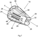
- Each holding portion 26 is configured to hold a respective one of the clamping members 14.
- the holding portions 26 are attached to the central portion 24 by hinges 28 in the form of flexure bearings, such as living hinges.
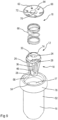
- the housing 16 comprises a body portion 52 having the internal surface 17.
- the internal surface 17 defines a through passage 54 along which the elongate article can extend.
- the internal surface 17 tapers from a wider region 56 of the through passage 54 to a narrower region 58 of the through passage 54.
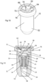
- the carriage 10 is disposed in the through passage 54 with the holding portions 26 in their closed position.
- the central portion 24 is arranged at the wider region 56 of the through passage 54, and the holding portions 26 extend from the central portion 24 to the narrower region 58.
- the elongate article is arranged in the through passage 54, extending along the path 32 defined between the holding portions 26.
- the housing 16 has a cooperating formation 68 to cooperate with the securing portions 66, thereby securing the reaction member 62 to the housing 16.
- the cooperating formation 68 is in the form of an annular groove defined in the internal surface 17 of the housing 16 at the wider region 56 of the through passage 54.
- the securing portions 66 are resiliently deformable to allow the securing portion 66 to cooperate with the cooperating formation 68.
- the securing portions 66 are received in the groove to secure the reaction member 62 to the housing 16. When so secured, the reaction member 62 can apply the reaction force to the spring member 60 to allow the spring member 60 to urge the carriage 10 along the through passage 54.
- the carriage 10 further includes an annular seat formation 74 on which the spring member 60 can be seated.
- the seat formation 74 extends around the aperture 30 in the central portion 24, and projects from the central portion 24.
- the seat formation 74 is received by the opposite end region of the spring member 60.
- the movement of the carriage 10 along the through passage 54 causes the supporting strips 48 of the holding portions 26, and the sliding surface 50 of each clamping member 14 to slide along the internal surface 17.
- Each supporting strip 48 is deformed by this sliding, thereby allowing the sliding surface 50 of each clamping member 14 to be pressed against the internal surface 17 of the housing 16 as the clamping surface 44 of each clamping member 14 is clamps the elongate article therebetween.
- the housing 16 has a radially outwardly extending lip portion 78 on the body portion 52, at the wider region 56 of the through passage 54.
- the lip portion 78 is provided either to support an article on the clamping device 12 or to support the clamping device 12 on an article.
- the carriage 10 allows three clamping members 14 to be installed in the holding members, and held in place in the housing 16 by the retaining formations, thereby preventing misalignment and the danger of the clamping members 14 falling out of the clamping device 12.
- the carriage may include any other suitable number of holding portions, for example, two or four.
- the invention is defined in the appended claims.
Landscapes
- Engineering & Computer Science (AREA)
- General Engineering & Computer Science (AREA)
- Mechanical Engineering (AREA)
- Clamps And Clips (AREA)
- Automobile Manufacture Line, Endless Track Vehicle, Trailer (AREA)
- Load-Engaging Elements For Cranes (AREA)
- Forklifts And Lifting Vehicles (AREA)
- Knitting Machines (AREA)
- Coating Apparatus (AREA)
Claims (15)
- Klemmvorrichtung (12), die einen Schlitten (10), eine Vielzahl von Klemmelementen (14), ein Gehäuse (16) und eine Drückanordnung (18) umfasst, wobei der Schlitten (10) zum Halten der Vielzahl von Klemmelementen (14) in der Klemmvorrichtung (12) dient, wobei der Schlitten einen Mittelabschnitt (24) und eine Vielzahl von Halteabschnitten (26) zum Halten der Klemmelemente (14) umfasst, wobei jedes Klemmelement (14) in einem jeweiligen der Halteabschnitte (26) gehalten wird, wobei die Halteabschnitte (26) relativ zu dem Mittelabschnitt (24) zwischen einer offenen Stellung der Halteabschnitte (26) und einer geschlossenen Stellung der Halteabschnitte (26) klappbar sind, wobei der Schlitten (10) in dem Gehäuse (16) untergebracht ist, wenn die Halteabschnitte (26) in der geschlossenen Stellung sind, wobei die Drückanordnung (18) zum Drücken des Schlittens (10) entlang des Gehäuses (16) dient, dadurch gekennzeichnet, dass
die Drückanordnung (18) ein Federelement (60) und ein Rückwirkungselement (62) umfasst, um eine Rückwirkungskraft auf das Federelement (60) auszuüben. - Klemmvorrichtung (12) nach Anspruch 1, wobei sich die Halteabschnitte (26) in der offenen Stellung von dem Mittelabschnitt (24) radial nach außen erstrecken und wobei sich die Halteabschnitte (26) in der geschlossenen Stellung über den Mittelabschnitt (24) erstrecken.
- Klemmvorrichtung (12) nach Anspruch 1 oder 2, wobei der Mittelabschnitt (24) eine Öffnung (30) definiert, durch die sich ein länglicher Gegenstand erstrecken kann, und wobei in der geschlossenen Stellung die Halteabschnitte (26) einen zentralen Pfad (32) dazwischen zum Aufnehmen des länglichen Gegenstands dort hindurch definieren.
- Klemmvorrichtung (12) nach Anspruch 1, 2 oder 3, wobei die Halteabschnitte (26) durch entsprechende Scharniere (28) an dem Mittelabschnitt (24) befestigt sind.
- Klemmvorrichtung (12) nach einem der Ansprüche 1 bis 4, wobei jeder Halteabschnitt (26) einen Halteraum (34) definiert, in dem das jeweilige Klemmelement (14) aufgenommen werden kann.
- Klemmvorrichtung (12) nach Anspruch 5, wobei jeder Halteraum (34) länglich ist, und wobei jedes in einem jeweiligen Halteraum (34) aufzunehmende Klemmelement (14) länglich ist.
- Klemmvorrichtung (12) nach Anspruch 5 oder 6, wobei jeder Halteabschnitt (26) Rückhalteausbildungen (38, 40) zum Zurückhalten des Klemmelements (14) im Halteraum (34) aufweist, wobei optional die Rückhalteausbildungen (38, 40) jedes Halteabschnitts (26) eine Hakenausbildung (38) zum Einhaken über das Klemmelement (14) umfassen.
- Klemmvorrichtung (12) nach einem der Ansprüche 5 bis 7, wobei jeder Halteabschnitt (26) eine Einführöffnung (42) definiert, durch die das Klemmelement (14) in den Halteraum (34) eingeführt werden kann, und wobei, wenn sich das Klemmelement (14) in dem Halteraum (34) befindet: eine Klemmfläche (44) des Klemmelements (14) durch die Einführöffnung (42) nach außen weist; oder das Klemmelement (14) durch die Einführöffnung (42) aus dem Halteraum (34) herausragt, wobei die Klemmfläche (44) nach außen weist.
- Klemmvorrichtung (12) nach Anspruch 8, wobei das Klemmelement (14) eine Gleitfläche (50) gegenüber der Klemmfläche (44) aufweist, wobei die Gleitfläche (50) entlang einer Fläche (17) der Klemmvorrichtung (12) verschiebbar ist, sodass sich im Gebrauch während des Klemmens eines länglichen Gegenstands die Gleitfläche (50) entlang der Fläche (17) der Klemmvorrichtung (12) bewegen kann.
- Klemmvorrichtung (12) nach einem der Ansprüche 5 bis 9, wobei jeder Halteabschnitt (26) eine Stützausbildung (48) zum Stützen des Klemmelements (14) im Halteraum (34) aufweist.
- Klemmvorrichtung (12) nach Anspruch 9 und 10, wobei die oder jede Stützausbildung (48) durch das Klemmelement (14) während des Klemmens des länglichen Gegenstands verformbar ist, um der Gleitfläche (50) zu ermöglichen, gegen die Fläche (17) der Klemmvorrichtung (12) geklemmt zu werden.
- Klemmvorrichtung (12) nach einem der Ansprüche 1 bis 11, wobei der Schlitten (10) eine Sitzausbildung (74) umfasst, auf der das Federelement (60) aufsetzbar ist.
- Klemmvorrichtung (12) nach einem der Ansprüche 1 bis 12, wobei das Gehäuse (16) eine Durchgangskanal (54) definiert, entlang dessen sich ein länglicher Gegenstand erstrecken kann, und wobei der Schlitten (10) und die Drückanordnung (18) in dem Kanal angeordnet sind.
- Klemmvorrichtung (12) nach Anspruch 13, wobei das Gehäuse (16) eine innere Fläche (17) aufweist, die den Durchgangskanal (54) definiert, wobei sich die innere Fläche (17) von einem breiteren Bereich (56) des Durchgangskanals (54) zu einem engeren Bereich (58) des Durchgangskanals (54) verjüngt, und wobei die Drückanordnung (18) den Schlitten (10) entlang des Durchgangskanals (54) von dem breiteren Bereich (56) des Durchgangskanals (54) zu dem engeren Bereich (58) des Durchgangskanals (54) drückt, wobei optional das Drücken des Schlittens (10) von dem breiteren Bereich (56) zu dem engeren Bereich (58) des Durchgangskanals (54) die Klemmelemente (14) nach innen zueinander drückt.
- Klemmvorrichtung (12) nach einem der Ansprüche 1 bis 14, wobei das Rückwirkungselement (62) an dem Gehäuse (16) befestigt ist, wobei das Rückwirkungselement (62) einen Befestigungsabschnitt (66) umfasst, und wobei das Gehäuse (16) eine zusammenwirkende Formation (68) aufweist, um mit dem Befestigungsabschnitt (66) zusammenzuwirken, wodurch das Rückwirkungselement (62) an dem Gehäuse (16) befestigt wird, wobei optional das Rückwirkungselement (62) elastisch verformbar ist, um dem Befestigungsabschnitt (66) zu ermöglichen, mit der zusammenwirkenden Formation (68) zusammenzuwirken.
Applications Claiming Priority (3)
| Application Number | Priority Date | Filing Date | Title |
|---|---|---|---|
| GBGB2017428.0A GB202017428D0 (en) | 2020-11-04 | 2020-11-04 | Improvements in or relating to carriages and clamping devices |
| GB2115385.3A GB2602384B (en) | 2020-11-04 | 2021-10-26 | Improvements in or relating to carriages and clamping devices |
| PCT/IB2021/059912 WO2022096987A1 (en) | 2020-11-04 | 2021-10-27 | Improvements in or relating to carriages and clamping devices |
Publications (3)
| Publication Number | Publication Date |
|---|---|
| EP4240982A1 EP4240982A1 (de) | 2023-09-13 |
| EP4240982C0 EP4240982C0 (de) | 2024-07-10 |
| EP4240982B1 true EP4240982B1 (de) | 2024-07-10 |
Family
ID=73776467
Family Applications (1)
| Application Number | Title | Priority Date | Filing Date |
|---|---|---|---|
| EP21819573.3A Active EP4240982B1 (de) | 2020-11-04 | 2021-10-27 | Verbesserungen an oder im zusammenhang mit wagen und klemmvorrichtungen |
Country Status (7)
| Country | Link |
|---|---|
| US (1) | US12140203B2 (de) |
| EP (1) | EP4240982B1 (de) |
| AU (1) | AU2021374901A1 (de) |
| CA (1) | CA3196305A1 (de) |
| ES (1) | ES2995159T3 (de) |
| GB (2) | GB202017428D0 (de) |
| WO (1) | WO2022096987A1 (de) |
Family Cites Families (19)
| Publication number | Priority date | Publication date | Assignee | Title |
|---|---|---|---|---|
| GB2079831B (en) * | 1980-07-14 | 1984-07-11 | Hayes Derek | Improvements in gripping or locating devices |
| US5127915A (en) * | 1984-10-29 | 1992-07-07 | Mattson Philip D | Surgical instrument for severing and clamping an umbilical cord |
| FR2606560B1 (fr) * | 1986-11-06 | 1989-03-03 | Lienart Jean Pierre | Pince d'ancrage pour conducteur electrique isole equipe d'un cable porteur egalement isole |
| DE4039822C1 (de) * | 1990-12-13 | 1992-07-23 | A. Raymond Kg, 7850 Loerrach, De | |
| US5289613A (en) * | 1992-02-12 | 1994-03-01 | Kohl Michael L | Cord end cover |
| US5323674A (en) * | 1993-01-26 | 1994-06-28 | Fidkowski Edward J | Cordless drive power driven accessory clamp |
| US5669590A (en) * | 1995-12-04 | 1997-09-23 | Yazaki Corporation | Retaining clip with multiple clamps |
| US5921991A (en) * | 1997-10-23 | 1999-07-13 | Biomax Technologies Inc. | Multi-colored umbilical cord clamp |
| US20020001504A1 (en) | 2000-01-10 | 2002-01-03 | Mccallion James P. | Threaded compression-enhanced fastening device for use with threaded rods |
| US7219399B2 (en) * | 2005-09-30 | 2007-05-22 | Hubbell Incorporated | Trigger actuated cable clamp |
| US8910912B2 (en) * | 2009-09-02 | 2014-12-16 | Illinois Tool Works Inc. | Conductive floating pipe assembly clip |
| US9954307B2 (en) * | 2013-03-28 | 2018-04-24 | Cameron Stuart Tait | Connector plug and socket having a wire clamping configuration |
| US9382757B1 (en) * | 2013-10-31 | 2016-07-05 | James Kirk | Blind pull |
| US9948080B2 (en) * | 2015-12-30 | 2018-04-17 | Preformed Line Products Co. | Cable spacer clamp arm liner |
| GB2549519A (en) * | 2016-04-21 | 2017-10-25 | Bio Pure Tech Ltd | A clamp |
| US10436352B2 (en) * | 2017-11-09 | 2019-10-08 | R. A. Phillips Industries, Inc. | Conduit clamp |
| US11079048B2 (en) * | 2018-06-13 | 2021-08-03 | TKO Clamping Systems, LLC | Clamping devices, systems and methods |
| US11187358B2 (en) * | 2018-10-18 | 2021-11-30 | Applied Seals North America, Inc. | Universal vacuum fitting clamp with torque control |
| EP3783235A1 (de) | 2019-08-21 | 2021-02-24 | Hilti Aktiengesellschaft | Steckereinsatz mit stangenaufnahmebohrung |
-
2020
- 2020-11-04 GB GBGB2017428.0A patent/GB202017428D0/en not_active Ceased
-
2021
- 2021-10-26 GB GB2115385.3A patent/GB2602384B/en active Active
- 2021-10-27 EP EP21819573.3A patent/EP4240982B1/de active Active
- 2021-10-27 ES ES21819573T patent/ES2995159T3/es active Active
- 2021-10-27 AU AU2021374901A patent/AU2021374901A1/en not_active Abandoned
- 2021-10-27 WO PCT/IB2021/059912 patent/WO2022096987A1/en not_active Ceased
- 2021-10-27 CA CA3196305A patent/CA3196305A1/en active Pending
- 2021-10-27 US US18/029,577 patent/US12140203B2/en active Active
Also Published As
| Publication number | Publication date |
|---|---|
| US20230375071A1 (en) | 2023-11-23 |
| EP4240982C0 (de) | 2024-07-10 |
| WO2022096987A1 (en) | 2022-05-12 |
| US12140203B2 (en) | 2024-11-12 |
| GB2602384B (en) | 2023-04-19 |
| AU2021374901A1 (en) | 2023-06-08 |
| CA3196305A1 (en) | 2022-05-12 |
| EP4240982A1 (de) | 2023-09-13 |
| GB2602384A (en) | 2022-06-29 |
| ES2995159T3 (en) | 2025-02-07 |
| GB202115385D0 (en) | 2021-12-08 |
| AU2021374901A9 (en) | 2025-03-13 |
| GB202017428D0 (en) | 2020-12-16 |
Similar Documents
| Publication | Publication Date | Title |
|---|---|---|
| US20170219126A1 (en) | Clip, a clamp assembly, and a mounting structure | |
| US11649878B2 (en) | Clamping device | |
| EP2668419B1 (de) | Klemmvorrichtung | |
| CN113597522B (zh) | 固定装置 | |
| CA2070144A1 (en) | Wire bundle retainer | |
| EP3066725B1 (de) | Verbinder vom steckertyp | |
| EP2912342B1 (de) | Klemmvorrichtung | |
| BR102015031300A2 (pt) | conjunto de conector de encaixe de extremidade operável com uma mão | |
| US10113317B1 (en) | Apparatus and method for hanging architectural panels with concealed attachment points | |
| KR101928994B1 (ko) | 전선볼트용 안전로프 고정장치 | |
| US12140203B2 (en) | Carriages and clamping devices | |
| US7422404B2 (en) | Facilitated tightening device | |
| WO2000075550A1 (en) | Hollow member connector | |
| CN115803972A (zh) | 模块化插头连接器 | |
| JP2018190727A (ja) | プラグ、およびプラグに振動保護を付与する方法 | |
| US7290739B2 (en) | Clamp support | |
| US4343451A (en) | Sensor retaining system | |
| US5820082A (en) | Holding element | |
| CN113305751B (zh) | 多部件夹具 | |
| CN110848243A (zh) | 具有夹具保持系统的球窝组件 | |
| JP6979166B2 (ja) | 挟持構造及び該挟持構造を備える接地端子 | |
| EP1353426A2 (de) | Verbesserungen an Kabelrinnen | |
| AU4527800A (en) | Hollow member connector |
Legal Events
| Date | Code | Title | Description |
|---|---|---|---|
| STAA | Information on the status of an ep patent application or granted ep patent |
Free format text: STATUS: UNKNOWN |
|
| STAA | Information on the status of an ep patent application or granted ep patent |
Free format text: STATUS: THE INTERNATIONAL PUBLICATION HAS BEEN MADE |
|
| PUAI | Public reference made under article 153(3) epc to a published international application that has entered the european phase |
Free format text: ORIGINAL CODE: 0009012 |
|
| STAA | Information on the status of an ep patent application or granted ep patent |
Free format text: STATUS: REQUEST FOR EXAMINATION WAS MADE |
|
| 17P | Request for examination filed |
Effective date: 20230518 |
|
| AK | Designated contracting states |
Kind code of ref document: A1 Designated state(s): AL AT BE BG CH CY CZ DE DK EE ES FI FR GB GR HR HU IE IS IT LI LT LU LV MC MK MT NL NO PL PT RO RS SE SI SK SM TR |
|
| DAV | Request for validation of the european patent (deleted) | ||
| DAX | Request for extension of the european patent (deleted) | ||
| GRAP | Despatch of communication of intention to grant a patent |
Free format text: ORIGINAL CODE: EPIDOSNIGR1 |
|
| STAA | Information on the status of an ep patent application or granted ep patent |
Free format text: STATUS: GRANT OF PATENT IS INTENDED |
|
| INTG | Intention to grant announced |
Effective date: 20240419 |
|
| GRAS | Grant fee paid |
Free format text: ORIGINAL CODE: EPIDOSNIGR3 |
|
| GRAA | (expected) grant |
Free format text: ORIGINAL CODE: 0009210 |
|
| STAA | Information on the status of an ep patent application or granted ep patent |
Free format text: STATUS: THE PATENT HAS BEEN GRANTED |
|
| RBV | Designated contracting states (corrected) |
Designated state(s): AL AT BE BG CH CY CZ DE DK EE ES FI FR GR HR HU IE IS IT LI LT LU LV MC MK MT NL NO PL PT RO RS SE SI SK SM TR |
|
| AK | Designated contracting states |
Kind code of ref document: B1 Designated state(s): AL AT BE BG CH CY CZ DE DK EE ES FI FR GR HR HU IE IS IT LI LT LU LV MC MK MT NL NO PL PT RO RS SE SI SK SM TR |
|
| REG | Reference to a national code |
Ref country code: CH Ref legal event code: EP |
|
| REG | Reference to a national code |
Ref country code: DE Ref legal event code: R096 Ref document number: 602021015620 Country of ref document: DE |
|
| U01 | Request for unitary effect filed |
Effective date: 20240731 |
|
| U07 | Unitary effect registered |
Designated state(s): AT BE BG DE DK EE FI FR IT LT LU LV MT NL PT SE SI Effective date: 20240819 |
|
| U20 | Renewal fee for the european patent with unitary effect paid |
Year of fee payment: 4 Effective date: 20241028 |
|
| PG25 | Lapsed in a contracting state [announced via postgrant information from national office to epo] |
Ref country code: NO Free format text: LAPSE BECAUSE OF FAILURE TO SUBMIT A TRANSLATION OF THE DESCRIPTION OR TO PAY THE FEE WITHIN THE PRESCRIBED TIME-LIMIT Effective date: 20241010 |
|
| PG25 | Lapsed in a contracting state [announced via postgrant information from national office to epo] |
Ref country code: GR Free format text: LAPSE BECAUSE OF FAILURE TO SUBMIT A TRANSLATION OF THE DESCRIPTION OR TO PAY THE FEE WITHIN THE PRESCRIBED TIME-LIMIT Effective date: 20241011 Ref country code: PL Free format text: LAPSE BECAUSE OF FAILURE TO SUBMIT A TRANSLATION OF THE DESCRIPTION OR TO PAY THE FEE WITHIN THE PRESCRIBED TIME-LIMIT Effective date: 20240710 |
|
| PG25 | Lapsed in a contracting state [announced via postgrant information from national office to epo] |
Ref country code: IS Free format text: LAPSE BECAUSE OF FAILURE TO SUBMIT A TRANSLATION OF THE DESCRIPTION OR TO PAY THE FEE WITHIN THE PRESCRIBED TIME-LIMIT Effective date: 20241110 |
|
| PG25 | Lapsed in a contracting state [announced via postgrant information from national office to epo] |
Ref country code: HR Free format text: LAPSE BECAUSE OF FAILURE TO SUBMIT A TRANSLATION OF THE DESCRIPTION OR TO PAY THE FEE WITHIN THE PRESCRIBED TIME-LIMIT Effective date: 20240710 |
|
| PG25 | Lapsed in a contracting state [announced via postgrant information from national office to epo] |
Ref country code: RS Free format text: LAPSE BECAUSE OF FAILURE TO SUBMIT A TRANSLATION OF THE DESCRIPTION OR TO PAY THE FEE WITHIN THE PRESCRIBED TIME-LIMIT Effective date: 20241010 |
|
| PG25 | Lapsed in a contracting state [announced via postgrant information from national office to epo] |
Ref country code: RS Free format text: LAPSE BECAUSE OF FAILURE TO SUBMIT A TRANSLATION OF THE DESCRIPTION OR TO PAY THE FEE WITHIN THE PRESCRIBED TIME-LIMIT Effective date: 20241010 Ref country code: PL Free format text: LAPSE BECAUSE OF FAILURE TO SUBMIT A TRANSLATION OF THE DESCRIPTION OR TO PAY THE FEE WITHIN THE PRESCRIBED TIME-LIMIT Effective date: 20240710 Ref country code: NO Free format text: LAPSE BECAUSE OF FAILURE TO SUBMIT A TRANSLATION OF THE DESCRIPTION OR TO PAY THE FEE WITHIN THE PRESCRIBED TIME-LIMIT Effective date: 20241010 Ref country code: IS Free format text: LAPSE BECAUSE OF FAILURE TO SUBMIT A TRANSLATION OF THE DESCRIPTION OR TO PAY THE FEE WITHIN THE PRESCRIBED TIME-LIMIT Effective date: 20241110 Ref country code: HR Free format text: LAPSE BECAUSE OF FAILURE TO SUBMIT A TRANSLATION OF THE DESCRIPTION OR TO PAY THE FEE WITHIN THE PRESCRIBED TIME-LIMIT Effective date: 20240710 Ref country code: GR Free format text: LAPSE BECAUSE OF FAILURE TO SUBMIT A TRANSLATION OF THE DESCRIPTION OR TO PAY THE FEE WITHIN THE PRESCRIBED TIME-LIMIT Effective date: 20241011 |
|
| REG | Reference to a national code |
Ref country code: ES Ref legal event code: FG2A Ref document number: 2995159 Country of ref document: ES Kind code of ref document: T3 Effective date: 20250207 |
|
| PG25 | Lapsed in a contracting state [announced via postgrant information from national office to epo] |
Ref country code: SM Free format text: LAPSE BECAUSE OF FAILURE TO SUBMIT A TRANSLATION OF THE DESCRIPTION OR TO PAY THE FEE WITHIN THE PRESCRIBED TIME-LIMIT Effective date: 20240710 |
|
| PG25 | Lapsed in a contracting state [announced via postgrant information from national office to epo] |
Ref country code: CZ Free format text: LAPSE BECAUSE OF FAILURE TO SUBMIT A TRANSLATION OF THE DESCRIPTION OR TO PAY THE FEE WITHIN THE PRESCRIBED TIME-LIMIT Effective date: 20240710 |
|
| PG25 | Lapsed in a contracting state [announced via postgrant information from national office to epo] |
Ref country code: SK Free format text: LAPSE BECAUSE OF FAILURE TO SUBMIT A TRANSLATION OF THE DESCRIPTION OR TO PAY THE FEE WITHIN THE PRESCRIBED TIME-LIMIT Effective date: 20240710 |
|
| PLBE | No opposition filed within time limit |
Free format text: ORIGINAL CODE: 0009261 |
|
| STAA | Information on the status of an ep patent application or granted ep patent |
Free format text: STATUS: NO OPPOSITION FILED WITHIN TIME LIMIT |
|
| REG | Reference to a national code |
Ref country code: CH Ref legal event code: PL |
|
| 26N | No opposition filed |
Effective date: 20250411 |
|
| PG25 | Lapsed in a contracting state [announced via postgrant information from national office to epo] |
Ref country code: MC Free format text: LAPSE BECAUSE OF FAILURE TO SUBMIT A TRANSLATION OF THE DESCRIPTION OR TO PAY THE FEE WITHIN THE PRESCRIBED TIME-LIMIT Effective date: 20240710 |
|
| PG25 | Lapsed in a contracting state [announced via postgrant information from national office to epo] |
Ref country code: CH Free format text: LAPSE BECAUSE OF NON-PAYMENT OF DUE FEES Effective date: 20241031 |
|
| PG25 | Lapsed in a contracting state [announced via postgrant information from national office to epo] |
Ref country code: IE Free format text: LAPSE BECAUSE OF NON-PAYMENT OF DUE FEES Effective date: 20241027 |
|
| PG25 | Lapsed in a contracting state [announced via postgrant information from national office to epo] |
Ref country code: RO Free format text: LAPSE BECAUSE OF FAILURE TO SUBMIT A TRANSLATION OF THE DESCRIPTION OR TO PAY THE FEE WITHIN THE PRESCRIBED TIME-LIMIT Effective date: 20240710 |
|
| U20 | Renewal fee for the european patent with unitary effect paid |
Year of fee payment: 5 Effective date: 20251031 |
|
| PG25 | Lapsed in a contracting state [announced via postgrant information from national office to epo] |
Ref country code: CY Free format text: LAPSE BECAUSE OF FAILURE TO SUBMIT A TRANSLATION OF THE DESCRIPTION OR TO PAY THE FEE WITHIN THE PRESCRIBED TIME-LIMIT; INVALID AB INITIO Effective date: 20211027 |
|
| PGFP | Annual fee paid to national office [announced via postgrant information from national office to epo] |
Ref country code: ES Payment date: 20251114 Year of fee payment: 5 |
|
| PG25 | Lapsed in a contracting state [announced via postgrant information from national office to epo] |
Ref country code: HU Free format text: LAPSE BECAUSE OF FAILURE TO SUBMIT A TRANSLATION OF THE DESCRIPTION OR TO PAY THE FEE WITHIN THE PRESCRIBED TIME-LIMIT; INVALID AB INITIO Effective date: 20211027 |