EP4240571B1 - Extrusionsvorrichtung zur herstellung eines produkts auf basis einer kautschukmischung - Google Patents
Extrusionsvorrichtung zur herstellung eines produkts auf basis einer kautschukmischung Download PDFInfo
- Publication number
- EP4240571B1 EP4240571B1 EP21802310.9A EP21802310A EP4240571B1 EP 4240571 B1 EP4240571 B1 EP 4240571B1 EP 21802310 A EP21802310 A EP 21802310A EP 4240571 B1 EP4240571 B1 EP 4240571B1
- Authority
- EP
- European Patent Office
- Prior art keywords
- roller
- rubber mixture
- vault
- threads
- extrusion
- Prior art date
- Legal status (The legal status is an assumption and is not a legal conclusion. Google has not performed a legal analysis and makes no representation as to the accuracy of the status listed.)
- Active
Links
Images


Classifications
-
- B—PERFORMING OPERATIONS; TRANSPORTING
- B29—WORKING OF PLASTICS; WORKING OF SUBSTANCES IN A PLASTIC STATE IN GENERAL
- B29C—SHAPING OR JOINING OF PLASTICS; SHAPING OF MATERIAL IN A PLASTIC STATE, NOT OTHERWISE PROVIDED FOR; AFTER-TREATMENT OF THE SHAPED PRODUCTS, e.g. REPAIRING
- B29C48/00—Extrusion moulding, i.e. expressing the moulding material through a die or nozzle which imparts the desired form; Apparatus therefor
- B29C48/25—Component parts, details or accessories; Auxiliary operations
- B29C48/36—Means for plasticising or homogenising the moulding material or forcing it through the nozzle or die
- B29C48/465—Means for plasticising or homogenising the moulding material or forcing it through the nozzle or die using rollers
- B29C48/467—Means for plasticising or homogenising the moulding material or forcing it through the nozzle or die using rollers using single rollers, e.g. provided with protrusions, closely surrounded by a housing with movement of the material in the axial direction
- B29C48/468—Cavity transfer mixing devices, i.e. a roller and surrounding barrel both provided with cavities; Barrels and rollers therefor
-
- B—PERFORMING OPERATIONS; TRANSPORTING
- B29—WORKING OF PLASTICS; WORKING OF SUBSTANCES IN A PLASTIC STATE IN GENERAL
- B29C—SHAPING OR JOINING OF PLASTICS; SHAPING OF MATERIAL IN A PLASTIC STATE, NOT OTHERWISE PROVIDED FOR; AFTER-TREATMENT OF THE SHAPED PRODUCTS, e.g. REPAIRING
- B29C48/00—Extrusion moulding, i.e. expressing the moulding material through a die or nozzle which imparts the desired form; Apparatus therefor
- B29C48/25—Component parts, details or accessories; Auxiliary operations
- B29C48/30—Extrusion nozzles or dies
- B29C48/35—Extrusion nozzles or dies with rollers
-
- B—PERFORMING OPERATIONS; TRANSPORTING
- B29—WORKING OF PLASTICS; WORKING OF SUBSTANCES IN A PLASTIC STATE IN GENERAL
- B29C—SHAPING OR JOINING OF PLASTICS; SHAPING OF MATERIAL IN A PLASTIC STATE, NOT OTHERWISE PROVIDED FOR; AFTER-TREATMENT OF THE SHAPED PRODUCTS, e.g. REPAIRING
- B29C48/00—Extrusion moulding, i.e. expressing the moulding material through a die or nozzle which imparts the desired form; Apparatus therefor
- B29C48/022—Extrusion moulding, i.e. expressing the moulding material through a die or nozzle which imparts the desired form; Apparatus therefor characterised by the choice of material
-
- B—PERFORMING OPERATIONS; TRANSPORTING
- B29—WORKING OF PLASTICS; WORKING OF SUBSTANCES IN A PLASTIC STATE IN GENERAL
- B29C—SHAPING OR JOINING OF PLASTICS; SHAPING OF MATERIAL IN A PLASTIC STATE, NOT OTHERWISE PROVIDED FOR; AFTER-TREATMENT OF THE SHAPED PRODUCTS, e.g. REPAIRING
- B29C48/00—Extrusion moulding, i.e. expressing the moulding material through a die or nozzle which imparts the desired form; Apparatus therefor
- B29C48/03—Extrusion moulding, i.e. expressing the moulding material through a die or nozzle which imparts the desired form; Apparatus therefor characterised by the shape of the extruded material at extrusion
-
- B—PERFORMING OPERATIONS; TRANSPORTING
- B29—WORKING OF PLASTICS; WORKING OF SUBSTANCES IN A PLASTIC STATE IN GENERAL
- B29C—SHAPING OR JOINING OF PLASTICS; SHAPING OF MATERIAL IN A PLASTIC STATE, NOT OTHERWISE PROVIDED FOR; AFTER-TREATMENT OF THE SHAPED PRODUCTS, e.g. REPAIRING
- B29C48/00—Extrusion moulding, i.e. expressing the moulding material through a die or nozzle which imparts the desired form; Apparatus therefor
- B29C48/25—Component parts, details or accessories; Auxiliary operations
- B29C48/36—Means for plasticising or homogenising the moulding material or forcing it through the nozzle or die
- B29C48/465—Means for plasticising or homogenising the moulding material or forcing it through the nozzle or die using rollers
- B29C48/467—Means for plasticising or homogenising the moulding material or forcing it through the nozzle or die using rollers using single rollers, e.g. provided with protrusions, closely surrounded by a housing with movement of the material in the axial direction
-
- B—PERFORMING OPERATIONS; TRANSPORTING
- B29—WORKING OF PLASTICS; WORKING OF SUBSTANCES IN A PLASTIC STATE IN GENERAL
- B29C—SHAPING OR JOINING OF PLASTICS; SHAPING OF MATERIAL IN A PLASTIC STATE, NOT OTHERWISE PROVIDED FOR; AFTER-TREATMENT OF THE SHAPED PRODUCTS, e.g. REPAIRING
- B29C48/00—Extrusion moulding, i.e. expressing the moulding material through a die or nozzle which imparts the desired form; Apparatus therefor
- B29C48/03—Extrusion moulding, i.e. expressing the moulding material through a die or nozzle which imparts the desired form; Apparatus therefor characterised by the shape of the extruded material at extrusion
- B29C48/07—Flat, e.g. panels
- B29C48/08—Flat, e.g. panels flexible, e.g. films
-
- B—PERFORMING OPERATIONS; TRANSPORTING
- B29—WORKING OF PLASTICS; WORKING OF SUBSTANCES IN A PLASTIC STATE IN GENERAL
- B29C—SHAPING OR JOINING OF PLASTICS; SHAPING OF MATERIAL IN A PLASTIC STATE, NOT OTHERWISE PROVIDED FOR; AFTER-TREATMENT OF THE SHAPED PRODUCTS, e.g. REPAIRING
- B29C48/00—Extrusion moulding, i.e. expressing the moulding material through a die or nozzle which imparts the desired form; Apparatus therefor
- B29C48/25—Component parts, details or accessories; Auxiliary operations
- B29C48/78—Thermal treatment of the extrusion moulding material or of preformed parts or layers, e.g. by heating or cooling
- B29C48/80—Thermal treatment of the extrusion moulding material or of preformed parts or layers, e.g. by heating or cooling at the plasticising zone, e.g. by heating cylinders
-
- B—PERFORMING OPERATIONS; TRANSPORTING
- B29—WORKING OF PLASTICS; WORKING OF SUBSTANCES IN A PLASTIC STATE IN GENERAL
- B29K—INDEXING SCHEME ASSOCIATED WITH SUBCLASSES B29B, B29C OR B29D, RELATING TO MOULDING MATERIALS OR TO MATERIALS FOR MOULDS, REINFORCEMENTS, FILLERS OR PREFORMED PARTS, e.g. INSERTS
- B29K2021/00—Use of unspecified rubbers as moulding material
-
- B—PERFORMING OPERATIONS; TRANSPORTING
- B29—WORKING OF PLASTICS; WORKING OF SUBSTANCES IN A PLASTIC STATE IN GENERAL
- B29L—INDEXING SCHEME ASSOCIATED WITH SUBCLASS B29C, RELATING TO PARTICULAR ARTICLES
- B29L2007/00—Flat articles, e.g. films or sheets
- B29L2007/007—Narrow strips, e.g. ribbons, tapes, bands
-
- B—PERFORMING OPERATIONS; TRANSPORTING
- B29—WORKING OF PLASTICS; WORKING OF SUBSTANCES IN A PLASTIC STATE IN GENERAL
- B29L—INDEXING SCHEME ASSOCIATED WITH SUBCLASS B29C, RELATING TO PARTICULAR ARTICLES
- B29L2030/00—Pneumatic or solid tyres or parts thereof
Definitions
- the invention generally relates to the production of products prepared from a rubber mixture. More particularly, the invention relates to an extrusion device for producing a product in the form of a thin strip from a rubber mixture.
- the strip made may be very wide and may be deposited directly on a known device (including a tire building drum, or "drum"), or directly superposed at the outlet of the device upon another material (for example, one or more plies or layers already deposited on the drum).
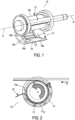
- the extrusion device 10 shown in Figures 1 and 2 and disclosed by the Applicant's patent EP1343624B1 .
- the extrusion device (or “device”) 10 includes a rotating roller (or “roller”) 12 that rotates about its axis X-X', having an outer surface 12a.
- the device 10 also includes a vault 14 with a wall 16 extending between a transverse end (hidden by the roller 12), where an inlet orifice is defined, and an opposite transverse end 16a, where an extrusion orifice is defined when the extrusion device 10 is closed.
- the extrusion orifice is delimited by the outer surface 12a of the roller 12 and an extrusion plate (or “plate”) 18 arranged towards the opposite transverse end 16a of the vault 14.
- the wall 16 which partially circumferentially covers at least part of the outer surface 12a of the roller 12, includes an inner surface 16b with projecting threads 16c oriented towards the roller 12 and separating consecutive sectors 16d.
- the roller 12 and the wall 16 delimit a gap between them that forms a chamber for plasticizing the rubber mixture from which the thin strip is formed.
- the roller 12 arranged relative to the vault 14 rotates in a predetermined direction (see the arrow A in Figure 2 ) depending on a direction of travel of a substrate on which the strip at the outlet of the device will be placed (see the arrow B in Figure 2 ).
- the rubber mixture introduced via the inlet orifice will follow a path as represented by the strip M.
- the rubber mixture introduced passes into the gap E 10 defined between the inner surface 16b of the wall 16 and the outer surface 12a of the roller 12.
- the rubber mixture passes the projecting threads 16c where significant shearing forces are created. Therefore, sometimes the material close to the roller continues to stick to the roller and passes by the projecting threads, which can result in particles of rubber in the strip formed thereby (for example, in the case where the projecting threads are not uniform).
- the invention thus relates to making, in the extrusion device shown, a groove in the form of a continuous helix on the outer surface of the roller to get rid of the particles. This helix, along with the rotation of the roller, removes any particles that may be present in the strip formed by the extrusion device.
- the invention relates to an extrusion device for forming as a thin strip a product based on a rubber mixture, the device including a rotating roller, an inlet orifice allowing the rubber mixture to flow and a vault circumferentially covering at least part of an outer surface of the roller, the vault having a wall bearing, on its inner surface oriented towards the roller, projecting threads so as to delimit with the surface of the roller a chamber for plasticizing the rubber mixture, the rubber mixture being driven from the inlet orifice towards an extrusion orifice into a gap defining the profile of the product, delimited by the wall of the vault and the outer surface of the roller, characterized in that:
- the extrusion device further includes an extrusion plate that adjustably delimits, with the outer surface of the roller, the extrusion orifice.
- each striation has a cross section of predetermined geometry, with a rounded shape at the bottom of each striation, and with pointed edges.
- an angle between the edges of the striations and the outer surface of the roller is less than or equal to 90°.
- the striations have a triangular cross section.
- the projecting threads include:
- the gap defining the profile of the product defines a product thickness of less than 5 mm.
- the vault is pivotably mounted about an axis of rotation borne by a support element of the roller.
- the invention also relates to a process for forming the rubber mixture produced by the disclosed extrusion device, the process including the following steps:
- the invention also relates to a tire production line, including at least one extrusion device of the type disclosed, arranged downstream of at least one extruder for extruding the rubber mixture.
- Figure 3 shows an embodiment of an extrusion device (or “device”) 100 for producing a product in the form of a thin strip from a rubber mixture.
- the device 100 may form part of an installation or of a tire production line.
- a rubber mixture (or “mixture”) introduced into the device 100 may include all materials necessary for producing the product, including, without limitation, an elastomer (for example, a natural rubber, a synthetic elastomer and combinations and equivalents thereof) and one or more ingredients, such as one or more processing agents, protective agents and reinforcing fillers.
- the materials may also include one or more other ingredients such as carbon black, silica, oils, resins and crosslinking or vulcanization agents.
- all ingredients are introduced in variable quantities depending on the performance desired from the products obtained by the mixing processes (for example, the tires).
- the device 100 includes a rotating roller (or "roller") 112 with a substantially circumferential outer surface 112a.
- the roller 112 has a center through which an axis of rotation X 112 -X 112' of the roller is defined.
- the roller 112 which extends axially between two opposite ends 112b, 112b', rotates about its axis of rotation relative to a shaft 114 that supports the roller.
- the roller 112 and the shaft 114 may be integrated or they may be supplied as two separate parts.
- the roller 112 also includes a pair of shoulders 112c of predetermined equal diameter.
- the device 100 further includes a vault (not shown) of the type included in the device 10 of Figures 1 and 2 and disclosed by the Applicant's patent EP1343624B1 .
- the vault includes a wall that circumferentially covers at least part of an outer surface 112a of the roller 112.
- the wall includes an inner surface with projecting threads oriented towards the roller.
- the inner surface of the wall has a substantially circumferential profile so as to direct a flow of the rubber mixture into a gap delimited between it and the outer surface 112a of the roller 112, which serves as a chamber for plasticizing the mixture.
- an inlet orifice and an opposite extrusion orifice are located, respectively.
- the mixture is driven from the inlet orifice, into the gap located between the wall of the vault and the outer surface 112a of the roller 112, towards the extrusion orifice.
- the vault is not divided into sectors but has at least two projecting threads extending substantially axially from the wall ("axial threads"). These two axial threads guide the mixture towards the extrusion orifice, distributing it over the width of the extrusion orifice.
- Other projecting threads in the vault may be oriented ("oriented threads") in different directions, such as helical threads or convergent or divergent threads, relative to the axial threads.
- Two flanges 116, 118 are mounted respectively on the two shoulders 112c, each flange axially bearing internally a shoulder (not shown) that interacts respectively with a corresponding end of the vault. This allows the vault to be secured to the device by one or more known securing means (for example, one or more screws or one or more equivalent means).
- support elements 120, 122 are mounted between the flanges 116, 118, respectively, the support elements being offset circumferentially relative to the roller 112.
- the support elements 120, 122 are rigidly secured to the flanges 116, 118 by any suitable means (such as screws or equivalent securing means). It is understood that the flanges 116, 118 and the support elements 120, 122 may be made in one piece.
- the vault may be pivotably mounted on the support element 120 so as to allow the device 100 to be opened and closed.
- the roller 112 may be mounted on a frame and rotated by a motor at a predetermined speed. The exact position of the roller 112 relative to the frame is adjustable according to the properties of the mixture and the strip formed (its width and its thickness).
- an extrusion plate (or "plate”), of the type described above in relation to Figures 1 and 2 , is arranged internally on the support element 120 in such a way that it delimits, with the outer surface 112a of the roller 112, the extrusion orifice. It is thus possible to adjust the spacing between the plate and the outer surface 112a of the roller 112 so as to define the height of the extrusion orifice according to the profile of the strip of rubber product to be obtained (for example, a thin strip).
- the plate may include one or more holes for the passage of textile yarns or metal wires so as to produce a reinforced strip that may be placed directly on a building drum or form.
- the roller 112 incorporates a means for controlling the temperature inside the roller, this means including, for example, a network including one or more feed channels 125 passing through the roller and one or more conveying grooves 127 (see Figure 5 ).
- a corresponding regulating fluid such as water, steam, a gas or another known temperature regulating fluid
- electricity is conveyed under the outer surface 112a of the roller 112 so as to regulate the temperature of the mixture during a process for forming the mixture.
- a groove 112R in the form of a continuous helix is made on the outer surface 112a of the roller 112 (the surface oriented towards the projecting threads on the vault).
- the continuous helix allows the flow of the rubber mixture to move forwards between the continuous helix and the projecting threads on the wall, effectively plasticizing the mixture.
- the continuous helix may include several striations 112Ra arranged one beside the other in the direction of movement of the mixture (see Figure 4 ).
- the striations 112Ra may be spaced apart from one another so as to create a thread of predetermined pitch.
- the striations 112Ra ensure that the rubber mixture moves forward relative to the peripheral direction during a process for forming the mixture.
- Each striation 112Ra forms a channel with a cross section of predetermined geometry (for example, triangular, circular, substantially rectangular, etc. cross section).
- a rounded shape is delimited at the bottom of each striation 112Ra, and pointed edges scrape the material during plasticization.
- An angle between the edges of the striations and the outer surface 112a of the roller 112 is, preferably, 90° or less.
- the roller 112 and the vault of the device 100 are assembled such that the crests of threads created by the continuous helix are tangential to the crests of threads on the vault.
- the crests are substantially in contact with one another. It is said that the crests are "substantially in contact” when the crests face one another with such a small space between them that a rubber material cannot catch on the surfaces of the crests, thereby preventing the formation of particles in the thin strip formed from the mixture.
- no product can get stuck on an outer surface 112a of the roller 112 or on the wall of the vault without being pushed by a thread as it rotates.
- the rubber mixture is introduced into the device 100 via the inlet orifice.
- the roller 112 conveys the mixture entering in the peripheral direction (see the arrow B in Figure 2 ) into the gap between the outer surface 112a of the roller and the inner surface of the wall of the vault.
- the rubber mixture immediately adjacent to the outer surface 112a of the roller 112 is scraped by edges of striations 112Ra as it moves forwards.
- a shearing energy which corresponds to the height of the striation and the speed of rotation of the roller 112, is conferred on the mixture, raising its temperature and breaking up the bigger particles or clumps in the mixture. Continuity of flow of the mixture is thus maintained so as to even out the temperature and obtain a homogeneous mixture.
- a "thin strip” is said to correspond to a strip with a thickness of less than 5 mm (in so far as the plasticization of the rubber mixture by the device is necessarily limited by the nature of the tool). In some embodiments of the device 100, this thickness is around 0.3 mm at the outlet of the device 100.
- a thicker strip could be produced, depending on the nature of the rubber mixture and the form in which it is introduced into the inlet orifice of the device (for example, using a mixture already worked prior to being introduced).
- any potential particles produced during a process for forming the mixture are removed from the thin strip emerging from the device 100. All of the material can be treated regularly and moderately, producing a very homogeneous end product that can be placed directly on a building drum or form.
- the device 100 may be arranged at the outlet of at least one extruder such that a mixture emerging from the extruder is directed towards the inlet orifice of the device. It is also understood that the device may be incorporated in a production line with an extruder for extruding several rubber mixtures and at least two devices 100 arranged downstream so as to allow several products (in other words, thin strips) to be deposited successively on a building drum.
- the mixture may pass between the rollers of a roller-die type system arranged just downstream of the extruder and upstream of the device 100.
- the rotation of the rollers may be managed by the quantity of mixture supplied (detected, for example, by a proximity sensor, by a pressure sensor or by an equivalent device) so as to form a continuous ply of predetermined thickness and width.
- a monitoring system could be installed. At least one part of the monitoring system may be supplied in a portable device such as a mobile network device (for example a mobile telephone, a laptop computer, a camera, one or more portable devices connected to the network (including “augmented reality” and/or “virtual reality” devices, portable clothing connected to the network and/or any combinations and/or any equivalents)).
- a mobile network device for example a mobile telephone, a laptop computer, a camera, one or more portable devices connected to the network (including "augmented reality” and/or “virtual reality” devices, portable clothing connected to the network and/or any combinations and/or any equivalents)).
- the device 100 may receive voice commands or other audio data (representing, for example, a start or stop of the process for forming the mixture).
- the request may include a request for the current state of a process for forming the rubber mixture.
- a response generated can be represented audibly, visually, in a tactile manner (for example by way of a haptic interface) and/or in a virtual and/or augmented manner.
- the process for forming the mixture performed by the device 100 of the invention may include a step of training the device 100 (or of training an installation or a tire production line incorporating the device 100) to recognize values representative of the thin strip (for example, values of length, width and thickness relative to the particles detected and removed) and to compare them with expected values.
- This step may include the step of training the device 100 to recognize a lack of equivalence between the compared values.
- Each training step may include a classification generated by self-learning means. This classification may include, without limitation, the parameters of the selected rubber mixture recipe, the durations of the processes for forming the mixture and the expected values during an ongoing tire production cycle.
- the data obtained may be fed into one or more neural networks that manage the device 100 and/or one or more installations or production lines incorporating the device 100.
Landscapes
- Engineering & Computer Science (AREA)
- Mechanical Engineering (AREA)
- Manufacturing & Machinery (AREA)
- Extrusion Moulding Of Plastics Or The Like (AREA)
Claims (10)
- Extrusionsvorrichtung (100) zum Ausbilden eines Produktes auf der Basis einer Kautschukmischung als einen dünnen Streifen, wobei die Vorrichtung eine sich drehende Walze (112), eine Einlassöffnung, die ein Strömen der Kautschukmischung ermöglicht, und eine Wölbung umfasst, die zumindest einen Teil einer Außenfläche (112a) der Walze (112) umlaufend bedeckt, wobei die Wölbung eine Wandung aufweist, die auf ihrer hin zur Walze (112) ausgerichteten Innenfläche vorstehende Gewinde trägt, um mit der Oberfläche der Walze eine Kammer zum Plastifizieren der Kautschukmischung abzugrenzen, wobei die Kautschukmischung von der Einlassöffnung hin zu einer Extrusionsöffnung in einen das Profil des Produkts definierenden Spalt getrieben wird, der durch die Wandung der Wölbung und die Außenfläche der Walze abgegrenzt ist, dadurch gekennzeichnet, dass:eine Nut (112R) in Form einer durchgehenden Spirale auf der Außenfläche (112a) der Walze (112) hergestellt ist, wobei die Nut mehrere Rillen (112Ra) umfasst, die nebeneinander in der Bewegungsrichtung der Kautschukmischung angeordnet sind, und wobei die Rillen (112Ra) derart voneinander beabstandet sind, dass ein Gewinde mit vorbestimmter Steigung erzeugt wird;so dass die Walze und die Wölbung derart zusammengefügt sind, dass durch die durchgehende Spirale erzeugte Gewindespitze und die Spitzen vorstehender Gewinde auf der Wölbung im Wesentlichen in Kontakt miteinander stehen.
- Vorrichtung (100) nach Anspruch 1, ferner umfassend eine Extrusionsplatte, die mit der Außenfläche (112a) der Walze (112) die Extrusionsöffnung einstellbar abgrenzt.
- Vorrichtung (100) nach Anspruch 2, wobei jede Rille (112Ra) einen Querschnitt einer vorbestimmten Geometrie mit einer abgerundeten Form an der Unterseite jeder Rille und mit spitzen Kanten aufweist.
- Vorrichtung (100) nach Anspruch 3, wobei ein Winkel zwischen den Kanten der Rillen und der Außenfläche der Walze kleiner als oder gleich 90° ist.
- Vorrichtung (100) nach Anspruch 3 oder Anspruch 4, wobei die Rillen (112Ra) einen dreieckigen Querschnitt aufweisen.
- Vorrichtung (100) nach einem der vorhergehenden Ansprüche, wobei die vorstehenden Gewinde Folgendes umfassen:- mindestens zwei axiale Gewinde, die sich im Wesentlichen axial von der Wandung der Wölbung hin zur Außenfläche (112a) der Walze (112) erstrecken; und- ein oder mehrere Gewinde, die relativ zu den axialen Gewinden in unterschiedliche Richtung ausgerichtet sind, die aus spiralförmigen Gewinden oder konvergierenden oder divergierenden Gewinden ausgewählt sind.
- Vorrichtung (100) nach einem der vorhergehenden Ansprüche, wobei der das Profil des Produkts definierende Spalt eine Dicke des Produkt von weniger als 5 mm definiert.
- Vorrichtung (100) nach einem der vorhergehenden Ansprüche, wobei die Wölbung um eine Drehachse schwenkbar montiert ist, die durch ein Stützelement (120) der Walze (112) getragen ist.
- Verfahren zum Ausbilden der Kautschukmischung, die durch die Vorrichtung (100) nach einem der Ansprüche 1 bis 8 hergestellt wird, umfassend die folgenden Schritte:- einen Schritt zum Einbringen der Kautschukmischung in die Vorrichtung (100) über die Einlassöffnung;- einen Schritt zum Fördern der Kautschukmischung in der Umfangsrichtung, wobei dieser Schritt von die Walze (112) durchgeführt wird, während sie sich dreht; und- einen Schritt, in dem die Kautschukmischung bis zur Extrusionsöffnung der Vorrichtung verläuft, bevor sie aus der Vorrichtung (100) in Form eines dünnen Streifens austritt.
- Reifenfertigungslinie, umfassend mindestens eine Vorrichtung (100) nach einem der Ansprüche 1 bis 8, die stromabwärts von mindestens einem Extruder zum Extrudieren der Kautschukmischung angeordnet ist.
Applications Claiming Priority (2)
| Application Number | Priority Date | Filing Date | Title |
|---|---|---|---|
| FR2011398A FR3116017B1 (fr) | 2020-11-06 | 2020-11-06 | Dispositif d’Extrusion Pour Fabriquer un Produit à Base d’un Mélange Caoutchouteux |
| PCT/EP2021/080090 WO2022096383A2 (en) | 2020-11-06 | 2021-10-29 | Extrusion device for producing a product based on a rubber mixture |
Publications (2)
| Publication Number | Publication Date |
|---|---|
| EP4240571A2 EP4240571A2 (de) | 2023-09-13 |
| EP4240571B1 true EP4240571B1 (de) | 2024-10-23 |
Family
ID=74206014
Family Applications (1)
| Application Number | Title | Priority Date | Filing Date |
|---|---|---|---|
| EP21802310.9A Active EP4240571B1 (de) | 2020-11-06 | 2021-10-29 | Extrusionsvorrichtung zur herstellung eines produkts auf basis einer kautschukmischung |
Country Status (5)
| Country | Link |
|---|---|
| US (1) | US20240009910A1 (de) |
| EP (1) | EP4240571B1 (de) |
| CN (1) | CN116600965A (de) |
| FR (1) | FR3116017B1 (de) |
| WO (1) | WO2022096383A2 (de) |
Family Cites Families (10)
| Publication number | Priority date | Publication date | Assignee | Title |
|---|---|---|---|---|
| DE1229279B (de) * | 1962-12-07 | 1966-11-24 | Helmut Alder Dipl Ing | Strangpresse zum Verarbeiten von plastischen oder plastifizierbaren Massen |
| CH423212A (it) * | 1964-07-07 | 1966-10-31 | Gabbrielli Ernesto Ing Dr | Procedimento atto alla eliminazione della flessione del cilindro rotorico nelle presse a rottura di strato limite |
| DD124023A1 (de) * | 1974-10-09 | 1977-02-02 | ||
| US5356208A (en) * | 1993-04-07 | 1994-10-18 | Zehev Tadmor | Screw element having shearing and scraping flights |
| FI965182A7 (fi) * | 1996-04-04 | 1997-10-05 | Conenor Oy | Menetelmä ja laite puristetun muovituotteen tekemiseksi ja muovituote |
| ATE315464T1 (de) * | 2000-11-27 | 2006-02-15 | Michelin Soc Tech | Extrusionsvorrichtung zur herstellung von produkten aus kautschukmischungen |
| JP2005169669A (ja) * | 2003-12-08 | 2005-06-30 | Nissei Plastics Ind Co | 可塑化スクリュ |
| CN106142486B (zh) * | 2015-04-10 | 2018-11-30 | 震雄机械(深圳)有限公司 | 射出成型机及其注射螺杆 |
| CN109849218A (zh) * | 2018-12-24 | 2019-06-07 | 青岛海诺中天科技股份有限公司 | 塑料泡沫颗粒覆膜干燥机用搅拌装置 |
| CN210911088U (zh) * | 2019-05-15 | 2020-07-03 | 广东天元实业集团股份有限公司 | 一种塑料挤出机 |
-
2020
- 2020-11-06 FR FR2011398A patent/FR3116017B1/fr active Active
-
2021
- 2021-10-29 WO PCT/EP2021/080090 patent/WO2022096383A2/en not_active Ceased
- 2021-10-29 US US18/035,651 patent/US20240009910A1/en active Pending
- 2021-10-29 EP EP21802310.9A patent/EP4240571B1/de active Active
- 2021-10-29 CN CN202180074234.9A patent/CN116600965A/zh active Pending
Also Published As
| Publication number | Publication date |
|---|---|
| US20240009910A1 (en) | 2024-01-11 |
| WO2022096383A2 (en) | 2022-05-12 |
| CN116600965A (zh) | 2023-08-15 |
| EP4240571A2 (de) | 2023-09-13 |
| FR3116017B1 (fr) | 2022-10-14 |
| FR3116017A1 (fr) | 2022-05-13 |
| WO2022096383A3 (en) | 2022-08-11 |
Similar Documents
| Publication | Publication Date | Title |
|---|---|---|
| CN108463328B (zh) | 用于挤出橡胶混合物的装置和方法 | |
| US5453238A (en) | Extrusion apparatus and method of extrusion for raw rubber mixes | |
| EP2734354A1 (de) | Gemeisselte extrusionsmatrize und verfahren zur einstellung der dicke eines extrudierten blechs | |
| US4365946A (en) | Apparatus for continuously processing rubber, elastomers, plastics and like materials which can be vulcanized or cross-linked | |
| CN113543947B (zh) | 具有移动元件的双螺杆混合挤出机 | |
| US8197242B2 (en) | Device and method for sheathing a ply of threads | |
| US7052267B2 (en) | Extrusion device for manufacturing a product based on a rubber mix | |
| EP4240571B1 (de) | Extrusionsvorrichtung zur herstellung eines produkts auf basis einer kautschukmischung | |
| US3089804A (en) | Process and apparatus for producing plastic net | |
| EP4240570B1 (de) | Komplexbildende vorrichtung zur herstellung eines komplexprodukts aus nicht hervorstehenden gummischichten | |
| FI74905B (fi) | Foerfarande foer framstaellning av extruderade roer samt anordning foer utfoerande av foerfarandet. | |
| EP3501807B1 (de) | Verfahren und vorrichtung zur herstellung einer gummiverstärkten komponente | |
| US20190001527A1 (en) | Extruder comprising a deflection element for targeted flow against perforated plate regions | |
| EP2993026B9 (de) | Vorrichtung zur steuerung der parameter von beschichtungsköpfen für wulstdrähte | |
| HK132997A (en) | A moired floor covering and a process for its manufacture | |
| KR20190096426A (ko) | 스크루식 압출기 | |
| RU2021135C1 (ru) | Многоручьевая экструзионная головка для полимерных материалов | |
| EP2516131B1 (de) | Extrusionsverfahren und vorrichtung zur herstellung von elastomerverbindungen | |
| RU2337825C2 (ru) | Способ изготовления эластомерных компонентов шины для колес транспортных средств | |
| WO1999038664A1 (en) | Extrudate shrinkage control and reduction | |
| CH715687A2 (de) | Mischvorrichtung, insbesondere zur Kautschukverarbeitung, sowie ein Verfahren zu deren Betrieb. | |
| SU844360A1 (ru) | Экструзионна головка дл нанесени пОлиМЕРНыХ пОКРыТий HA издЕли |
Legal Events
| Date | Code | Title | Description |
|---|---|---|---|
| STAA | Information on the status of an ep patent application or granted ep patent |
Free format text: STATUS: UNKNOWN |
|
| STAA | Information on the status of an ep patent application or granted ep patent |
Free format text: STATUS: THE INTERNATIONAL PUBLICATION HAS BEEN MADE |
|
| PUAI | Public reference made under article 153(3) epc to a published international application that has entered the european phase |
Free format text: ORIGINAL CODE: 0009012 |
|
| STAA | Information on the status of an ep patent application or granted ep patent |
Free format text: STATUS: REQUEST FOR EXAMINATION WAS MADE |
|
| 17P | Request for examination filed |
Effective date: 20230606 |
|
| AK | Designated contracting states |
Kind code of ref document: A2 Designated state(s): AL AT BE BG CH CY CZ DE DK EE ES FI FR GB GR HR HU IE IS IT LI LT LU LV MC MK MT NL NO PL PT RO RS SE SI SK SM TR |
|
| DAV | Request for validation of the european patent (deleted) | ||
| DAX | Request for extension of the european patent (deleted) | ||
| GRAP | Despatch of communication of intention to grant a patent |
Free format text: ORIGINAL CODE: EPIDOSNIGR1 |
|
| STAA | Information on the status of an ep patent application or granted ep patent |
Free format text: STATUS: GRANT OF PATENT IS INTENDED |
|
| INTG | Intention to grant announced |
Effective date: 20240701 |
|
| GRAS | Grant fee paid |
Free format text: ORIGINAL CODE: EPIDOSNIGR3 |
|
| GRAA | (expected) grant |
Free format text: ORIGINAL CODE: 0009210 |
|
| STAA | Information on the status of an ep patent application or granted ep patent |
Free format text: STATUS: THE PATENT HAS BEEN GRANTED |
|
| AK | Designated contracting states |
Kind code of ref document: B1 Designated state(s): AL AT BE BG CH CY CZ DE DK EE ES FI FR GB GR HR HU IE IS IT LI LT LU LV MC MK MT NL NO PL PT RO RS SE SI SK SM TR |
|
| REG | Reference to a national code |
Ref country code: GB Ref legal event code: FG4D |
|
| REG | Reference to a national code |
Ref country code: CH Ref legal event code: EP |
|
| REG | Reference to a national code |
Ref country code: DE Ref legal event code: R096 Ref document number: 602021020750 Country of ref document: DE |
|
| REG | Reference to a national code |
Ref country code: IE Ref legal event code: FG4D |
|
| REG | Reference to a national code |
Ref country code: LT Ref legal event code: MG9D |
|
| REG | Reference to a national code |
Ref country code: NL Ref legal event code: MP Effective date: 20241023 |
|
| REG | Reference to a national code |
Ref country code: AT Ref legal event code: MK05 Ref document number: 1734497 Country of ref document: AT Kind code of ref document: T Effective date: 20241023 |
|
| PG25 | Lapsed in a contracting state [announced via postgrant information from national office to epo] |
Ref country code: NL Free format text: LAPSE BECAUSE OF FAILURE TO SUBMIT A TRANSLATION OF THE DESCRIPTION OR TO PAY THE FEE WITHIN THE PRESCRIBED TIME-LIMIT Effective date: 20241023 |
|
| PG25 | Lapsed in a contracting state [announced via postgrant information from national office to epo] |
Ref country code: NL Free format text: LAPSE BECAUSE OF FAILURE TO SUBMIT A TRANSLATION OF THE DESCRIPTION OR TO PAY THE FEE WITHIN THE PRESCRIBED TIME-LIMIT Effective date: 20241023 |
|
| PG25 | Lapsed in a contracting state [announced via postgrant information from national office to epo] |
Ref country code: IS Free format text: LAPSE BECAUSE OF FAILURE TO SUBMIT A TRANSLATION OF THE DESCRIPTION OR TO PAY THE FEE WITHIN THE PRESCRIBED TIME-LIMIT Effective date: 20250223 Ref country code: HR Free format text: LAPSE BECAUSE OF FAILURE TO SUBMIT A TRANSLATION OF THE DESCRIPTION OR TO PAY THE FEE WITHIN THE PRESCRIBED TIME-LIMIT Effective date: 20241023 Ref country code: PT Free format text: LAPSE BECAUSE OF FAILURE TO SUBMIT A TRANSLATION OF THE DESCRIPTION OR TO PAY THE FEE WITHIN THE PRESCRIBED TIME-LIMIT Effective date: 20250224 |
|
| PG25 | Lapsed in a contracting state [announced via postgrant information from national office to epo] |
Ref country code: FI Free format text: LAPSE BECAUSE OF FAILURE TO SUBMIT A TRANSLATION OF THE DESCRIPTION OR TO PAY THE FEE WITHIN THE PRESCRIBED TIME-LIMIT Effective date: 20241023 |
|
| PG25 | Lapsed in a contracting state [announced via postgrant information from national office to epo] |
Ref country code: BG Free format text: LAPSE BECAUSE OF FAILURE TO SUBMIT A TRANSLATION OF THE DESCRIPTION OR TO PAY THE FEE WITHIN THE PRESCRIBED TIME-LIMIT Effective date: 20241023 |
|
| PG25 | Lapsed in a contracting state [announced via postgrant information from national office to epo] |
Ref country code: ES Free format text: LAPSE BECAUSE OF FAILURE TO SUBMIT A TRANSLATION OF THE DESCRIPTION OR TO PAY THE FEE WITHIN THE PRESCRIBED TIME-LIMIT Effective date: 20241023 |
|
| PG25 | Lapsed in a contracting state [announced via postgrant information from national office to epo] |
Ref country code: NO Free format text: LAPSE BECAUSE OF FAILURE TO SUBMIT A TRANSLATION OF THE DESCRIPTION OR TO PAY THE FEE WITHIN THE PRESCRIBED TIME-LIMIT Effective date: 20250123 |
|
| PG25 | Lapsed in a contracting state [announced via postgrant information from national office to epo] |
Ref country code: LV Free format text: LAPSE BECAUSE OF FAILURE TO SUBMIT A TRANSLATION OF THE DESCRIPTION OR TO PAY THE FEE WITHIN THE PRESCRIBED TIME-LIMIT Effective date: 20241023 Ref country code: AT Free format text: LAPSE BECAUSE OF FAILURE TO SUBMIT A TRANSLATION OF THE DESCRIPTION OR TO PAY THE FEE WITHIN THE PRESCRIBED TIME-LIMIT Effective date: 20241023 Ref country code: GR Free format text: LAPSE BECAUSE OF FAILURE TO SUBMIT A TRANSLATION OF THE DESCRIPTION OR TO PAY THE FEE WITHIN THE PRESCRIBED TIME-LIMIT Effective date: 20250124 |
|
| PG25 | Lapsed in a contracting state [announced via postgrant information from national office to epo] |
Ref country code: PL Free format text: LAPSE BECAUSE OF FAILURE TO SUBMIT A TRANSLATION OF THE DESCRIPTION OR TO PAY THE FEE WITHIN THE PRESCRIBED TIME-LIMIT Effective date: 20241023 |
|
| PG25 | Lapsed in a contracting state [announced via postgrant information from national office to epo] |
Ref country code: RS Free format text: LAPSE BECAUSE OF FAILURE TO SUBMIT A TRANSLATION OF THE DESCRIPTION OR TO PAY THE FEE WITHIN THE PRESCRIBED TIME-LIMIT Effective date: 20250123 |
|
| REG | Reference to a national code |
Ref country code: DE Ref legal event code: R119 Ref document number: 602021020750 Country of ref document: DE |
|
| REG | Reference to a national code |
Ref country code: CH Ref legal event code: PL |
|
| PG25 | Lapsed in a contracting state [announced via postgrant information from national office to epo] |
Ref country code: SM Free format text: LAPSE BECAUSE OF FAILURE TO SUBMIT A TRANSLATION OF THE DESCRIPTION OR TO PAY THE FEE WITHIN THE PRESCRIBED TIME-LIMIT Effective date: 20241023 |
|
| PG25 | Lapsed in a contracting state [announced via postgrant information from national office to epo] |
Ref country code: MC Free format text: LAPSE BECAUSE OF FAILURE TO SUBMIT A TRANSLATION OF THE DESCRIPTION OR TO PAY THE FEE WITHIN THE PRESCRIBED TIME-LIMIT Effective date: 20241023 |
|
| PG25 | Lapsed in a contracting state [announced via postgrant information from national office to epo] |
Ref country code: DE Free format text: LAPSE BECAUSE OF NON-PAYMENT OF DUE FEES Effective date: 20250501 |
|
| PG25 | Lapsed in a contracting state [announced via postgrant information from national office to epo] |
Ref country code: DK Free format text: LAPSE BECAUSE OF FAILURE TO SUBMIT A TRANSLATION OF THE DESCRIPTION OR TO PAY THE FEE WITHIN THE PRESCRIBED TIME-LIMIT Effective date: 20241023 |
|
| PG25 | Lapsed in a contracting state [announced via postgrant information from national office to epo] |
Ref country code: BE Free format text: LAPSE BECAUSE OF NON-PAYMENT OF DUE FEES Effective date: 20241031 Ref country code: LU Free format text: LAPSE BECAUSE OF NON-PAYMENT OF DUE FEES Effective date: 20241029 |
|
| PG25 | Lapsed in a contracting state [announced via postgrant information from national office to epo] |
Ref country code: EE Free format text: LAPSE BECAUSE OF FAILURE TO SUBMIT A TRANSLATION OF THE DESCRIPTION OR TO PAY THE FEE WITHIN THE PRESCRIBED TIME-LIMIT Effective date: 20241023 |
|
| PG25 | Lapsed in a contracting state [announced via postgrant information from national office to epo] |
Ref country code: CH Free format text: LAPSE BECAUSE OF NON-PAYMENT OF DUE FEES Effective date: 20241031 |
|
| PG25 | Lapsed in a contracting state [announced via postgrant information from national office to epo] |
Ref country code: RO Free format text: LAPSE BECAUSE OF FAILURE TO SUBMIT A TRANSLATION OF THE DESCRIPTION OR TO PAY THE FEE WITHIN THE PRESCRIBED TIME-LIMIT Effective date: 20241023 |
|
| PG25 | Lapsed in a contracting state [announced via postgrant information from national office to epo] |
Ref country code: SK Free format text: LAPSE BECAUSE OF FAILURE TO SUBMIT A TRANSLATION OF THE DESCRIPTION OR TO PAY THE FEE WITHIN THE PRESCRIBED TIME-LIMIT Effective date: 20241023 |
|
| PG25 | Lapsed in a contracting state [announced via postgrant information from national office to epo] |
Ref country code: CZ Free format text: LAPSE BECAUSE OF FAILURE TO SUBMIT A TRANSLATION OF THE DESCRIPTION OR TO PAY THE FEE WITHIN THE PRESCRIBED TIME-LIMIT Effective date: 20241023 |
|
| PG25 | Lapsed in a contracting state [announced via postgrant information from national office to epo] |
Ref country code: IT Free format text: LAPSE BECAUSE OF FAILURE TO SUBMIT A TRANSLATION OF THE DESCRIPTION OR TO PAY THE FEE WITHIN THE PRESCRIBED TIME-LIMIT Effective date: 20241023 |
|
| REG | Reference to a national code |
Ref country code: BE Ref legal event code: MM Effective date: 20241031 |
|
| PLBE | No opposition filed within time limit |
Free format text: ORIGINAL CODE: 0009261 |
|
| STAA | Information on the status of an ep patent application or granted ep patent |
Free format text: STATUS: NO OPPOSITION FILED WITHIN TIME LIMIT |
|
| PG25 | Lapsed in a contracting state [announced via postgrant information from national office to epo] |
Ref country code: SE Free format text: LAPSE BECAUSE OF FAILURE TO SUBMIT A TRANSLATION OF THE DESCRIPTION OR TO PAY THE FEE WITHIN THE PRESCRIBED TIME-LIMIT Effective date: 20241023 |
|
| 26N | No opposition filed |
Effective date: 20250724 |
|
| PG25 | Lapsed in a contracting state [announced via postgrant information from national office to epo] |
Ref country code: IE Free format text: LAPSE BECAUSE OF NON-PAYMENT OF DUE FEES Effective date: 20241029 |
|
| PGFP | Annual fee paid to national office [announced via postgrant information from national office to epo] |
Ref country code: FR Payment date: 20251030 Year of fee payment: 5 |
|
| PG25 | Lapsed in a contracting state [announced via postgrant information from national office to epo] |
Ref country code: HU Free format text: LAPSE BECAUSE OF FAILURE TO SUBMIT A TRANSLATION OF THE DESCRIPTION OR TO PAY THE FEE WITHIN THE PRESCRIBED TIME-LIMIT; INVALID AB INITIO Effective date: 20211029 |
|
| PG25 | Lapsed in a contracting state [announced via postgrant information from national office to epo] |
Ref country code: CY Free format text: LAPSE BECAUSE OF FAILURE TO SUBMIT A TRANSLATION OF THE DESCRIPTION OR TO PAY THE FEE WITHIN THE PRESCRIBED TIME-LIMIT; INVALID AB INITIO Effective date: 20211029 |