EP4240207B1 - Möbelstück mit magnetische regalkonsole zur lösbaren verbindung von regalen mit schultern - Google Patents
Möbelstück mit magnetische regalkonsole zur lösbaren verbindung von regalen mit schultern Download PDFInfo
- Publication number
- EP4240207B1 EP4240207B1 EP21810738.1A EP21810738A EP4240207B1 EP 4240207 B1 EP4240207 B1 EP 4240207B1 EP 21810738 A EP21810738 A EP 21810738A EP 4240207 B1 EP4240207 B1 EP 4240207B1
- Authority
- EP
- European Patent Office
- Prior art keywords
- pin
- shelf
- piece
- furniture
- slide
- Prior art date
- Legal status (The legal status is an assumption and is not a legal conclusion. Google has not performed a legal analysis and makes no representation as to the accuracy of the status listed.)
- Active
Links
Images

Classifications
-
- A—HUMAN NECESSITIES
- A47—FURNITURE; DOMESTIC ARTICLES OR APPLIANCES; COFFEE MILLS; SPICE MILLS; SUCTION CLEANERS IN GENERAL
- A47B—TABLES; DESKS; OFFICE FURNITURE; CABINETS; DRAWERS; GENERAL DETAILS OF FURNITURE
- A47B96/00—Details of cabinets, racks or shelf units not covered by a single one of groups A47B43/00 - A47B95/00; General details of furniture
- A47B96/06—Brackets or similar supporting means for cabinets, racks or shelves
- A47B96/066—Supporting means received within an edge of the shelf
-
- F—MECHANICAL ENGINEERING; LIGHTING; HEATING; WEAPONS; BLASTING
- F16—ENGINEERING ELEMENTS AND UNITS; GENERAL MEASURES FOR PRODUCING AND MAINTAINING EFFECTIVE FUNCTIONING OF MACHINES OR INSTALLATIONS; THERMAL INSULATION IN GENERAL
- F16B—DEVICES FOR FASTENING OR SECURING CONSTRUCTIONAL ELEMENTS OR MACHINE PARTS TOGETHER, e.g. NAILS, BOLTS, CIRCLIPS, CLAMPS, CLIPS OR WEDGES; JOINTS OR JOINTING
- F16B12/00—Jointing of furniture or the like, e.g. hidden from exterior
- F16B12/10—Jointing of furniture or the like, e.g. hidden from exterior using pegs, bolts, tenons, clamps, clips, or the like
- F16B12/12—Jointing of furniture or the like, e.g. hidden from exterior using pegs, bolts, tenons, clamps, clips, or the like for non-metal furniture parts, e.g. made of wood, of plastics
- F16B12/20—Jointing of furniture or the like, e.g. hidden from exterior using pegs, bolts, tenons, clamps, clips, or the like for non-metal furniture parts, e.g. made of wood, of plastics using clamps, clips, wedges, sliding bolts, or the like
Definitions
- the present invention relates to a shelf-supporting device for the reversible and easily removable connection of a shelf to the opposite shoulders of a piece of furniture.
- the device according to the present invention responds to the need, felt in the sector, for being able to provide furniture shelves with supporting devices that create a connection with the shoulders of an increasingly miniaturized piece of furniture, so as to minimize the aesthetic impact and possibly disappearing completely from sight when the shelf is assembled.
- the shelf-supporting device according to the present invention allows any hole on the surfaces of the shelf itself to be completely eliminated.
- shelf brackets Devices of the type considered herein for the reversible connection of a shelf to the shoulders of a piece of furniture are known in the field, and are commonly called shelf brackets. They are configured for being completely inserted within the thickness of the shelf itself, and have the function of stably but removably supporting and fixing the substantially horizontal shelf of a piece of furniture between two vertical elements of the piece of furniture itself, commonly called shoulders. Said shelves and said shoulders are substantially arranged perpendicular to each other.
- the document DE 102009060456 discloses joining means to detachably join adjacent components, furniture or parts thereof with two coupling elements comprising a pin and a receptacle for said pin wherein said coupling elements under influence of a temporary magnetic field actuation from outside of the joining means (1) interact with the actuation of the magnetic field, being the pin movable between a fixation position and a pre-position.
- US 4,848,812 discloses a device for selectively locking a door in a closed position against a door frame member.
- a magnetic bolt is disposed within the throughbore for slidable movement between a retracted position and an extended position in which a portion of the bolt extends outwardly.
- one drawback consists in the fact that the shelf brackets of the known type are not completely invisible when, with the device assembled, the shelf is viewed from above or below, and consequently do not limit the aesthetic impact on the furniture.
- known devices require the creation of holes in the lower surface and/or in the upper surface of the shelf itself to allow access to the device by means of a tool.
- the devices of the known type have proved to be relatively expensive to manufacture, also requiring the use of a manoeuvring tool that must be inserted into a hole formed in the shelf to allow the actuation of means for moving the pin provided in the device.
- This manoeuvre may not always be easy, and in any case requires locating the hole which should be as small as possible to limit its aesthetic impact. Locating the hole and inserting the tool, especially when the sides of the furniture are already assembled and the operator must intervene on the shelf brackets that are positioned towards the bottom panel of the furniture, is not a simple operation
- the objective of the present invention is to provide a shelf-supporting device which has a minimum aesthetic impact and which at the same time allows an easy and fast assembly and disassembly of the shelf with respect to the shoulders.
- An objective of the present invention is also to provide a supporting and fixing device for shelves that is more versatile in the design and installation phase of the furniture, in particular as it is able to minimize, if not completely cancel, the aesthetic impact, proving to be invisible both when used with shelves destined for being seen from above by the user, and with shelves destined for being seen from below, allowing any trace of the presence of the device and even the access holes for the tool to be completely eliminated from sight.
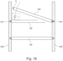
- a shelf-supporting device 10, 10' for supporting furniture shelves suitable for creating the reversible connection of a shelf 100 to the opposite shoulders 200 of a piece of furniture.
- the supporting device 10, 10' is of the type suitable for creating a connection by means of a pin 11 associated with the shelf 100 and configured for protruding from the transverse edge B of said shelf 100 so as to be inserted into a corresponding hole or housing seat 201 formed on the shoulder 200 of a piece of furniture.
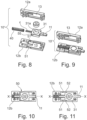
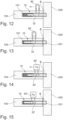
- the shelf-supporting device 10, 10' for the reversible connection is configured for being inserted into a seat 101 formed within the thickness of said shelf 100 and comprises a main body 12, advantageously composed of two coupled half-shells 12a, 12b, with which a connection pin 11 is slidingly associated, movable between an advanced operating position in which said pin 11 protrudes from said shelf 100, according to what can be seen for example in figures 12 and 14 , so as to be able to be inserted into a housing seat 201 formed on one of said shoulders 200, and a retracted non-operating position wherein the pin 11 does not protrude from said shelf 100, or protrudes so as to be able to be in any case released from said housing seat 201, for example by pushing the shelf itself upwards.
- the device 10, 10' is characterized in that the pin 11 is associated with axial movement means 30 of said pin 11 which can be actuated by the user by means of the magnetic interaction between the movement means 30 themselves and an external actuation device 60, 60' that the user can move with respect to the main body 12 of the shelf bracket 10, 10'.
- the axial movement means 30 of the pin 11 advantageously comprise at least a part or an insert 32 made of metallic material capable of interacting with the magnetic field generated by an external actuation device 60 comprising a magnet.
- the means 30 for moving the pin 11 comprise at least a part or an insert comprising a magnet 32', capable of interacting with the magnetic field generated by a external actuation device 60' made of metallic material.
- the axial movement means 30 of the pin 11 preferably comprise a slide 31 slidingly inserted in a housing seat 13 formed within said main body 12, and said slide 31 comprises a seat 31a for housing said at least a part or insert 32 made of metallic material or said at least one magnet 32'.
- the shelf-supporting device 10, 10' preferably further comprises elastic means 40 acting between said slide 31 and said main body 12, configured for keeping the pin 11 in the forward position, so that the opposing action of the elastic means 40 must be overcome in order to withdraw said pin 11.
- Said elastic means preferably comprise a helical spring 40 acting between said slide 31 and said main body 12 along the axial movement direction X of the pin 11.
- Said slide 31 advantageously has a substantially rectangular configuration and in an opposite position with respect to the pin 11, i.e. from the opposite side from which the pin 11 extends, a shank C extends coaxially with respect to the pin 11 along the direction X.
- the helical spring 40 is partially fitted onto said shank C.
- the shelf-supporting device 10' further comprises retaining means 50 capable of keeping the pin 11 in the retracted position against the action of said elastic means 40, as can be seen for example in figure 10 .
- Said retaining means 50 can be advantageously released by the user by moving the pin itself or the axial movement means 30 of the pin 11 by means of said external actuation device 60, 60'.
- the retaining means 50 advantageously comprise one or more teeth 51 provided on said main body 12, in particular on the internal side surface of said housing seat 13 of the slide 31, configured for being inserted into corresponding seats 52 formed on said slide 31, advantageously in correspondence with the side surfaces of the body of the slide 31.
- the configuration of the device, and in particular of the retaining means 50 and elastic means 40, is advantageously such that when the device is blocked with the pin in the retracted position as shown in figure 10 , an external action by the user involving the disengagement of the retaining means 50 is sufficient for releasing the device and causing the slide 31 and the pin 11 to advance into an operating position.
- the elastic means 40 are advantageously dimensioned so that once the retaining means 50 have been released, the slide 31 is pushed by the elastic means 40 into the advanced operating position shown in figure 11 .
- the force exerted by the elastic means 40 is preferably such as to cause the slide 31 to move forward causing the teeth 51 to pass beyond the seats 52 so that a retraction of the slide 31 can also cause the release of the retaining means 50 and the movement of the pin 11 from its non-operating position to an operating position.
- the engagement of the shelf bracket 10, 10' inserted in the shelf 100 with the seats 201 formed in the shoulders 200 of the furniture can be effected by simply guiding the positioning of the pins 11 in correspondence with the seats 201 as shown, the action of the elastic means 40 will cause the automatic insertion of the pin 11 into the seat 201.
Landscapes
- Engineering & Computer Science (AREA)
- General Engineering & Computer Science (AREA)
- Mechanical Engineering (AREA)
- Supports Or Holders For Household Use (AREA)
- Cabinets, Racks, Or The Like Of Rigid Construction (AREA)
Claims (8)
- Möbelstück, umfassend ein Regal (100) und Schultern (200) und eine Regalstützvorrichtung (10, 10') zur reversiblen Verbindung des Regals (100) mit den Schultern (200), wobei die Vorrichtung konfiguriert ist, in einen Sitz (101) eingesetzt zu werden, der innerhalb der Dicke des Regals (100) gebildet ist, und umfassend einen Hauptkörper (12), der gleitend einem Verbindungsstift (11) zugeordnet ist, der zwischen einer vorgeschobenen Betriebsposition, in der der Stift (11) aus dem Regal (100) herausragt, sodass er in einen Gehäusesitz (201), der auf einer der Schultern (200) gebildet ist, und einer zurückgeschobenen Nichtbetriebsposition, in der der Stift (11) nicht aus dem Regal (100) herausragt oder herausragt, sodass er in jedem Fall aus dem Gehäusesitz (201) gelöst werden kann, eingesetzt werden kann, dadurch gekennzeichnet, dass dem Stift (11) axiale Bewegungsmittel (30) des Stifts (11) zugeordnet sind, die durch den Benutzer durch die magnetische Interaktion zwischen den Bewegungsmitteln (30) und einer externen Betätigungsvorrichtung (60) betätigt werden können, und wobei die axialen Bewegungsmittel (30) des Stifts (11) einen Schieber (31) umfassen, der gleitend in einen Gehäusesitz (13) eingesetzt ist, der innerhalb des Hauptkörpers (12) gebildet ist, der Schieber (31) umfassend einen Sitz (31a), der mindestens einen Teil oder Einsatz (32) aufnimmt, der aus einem metallischen Material oder mindestens einem Magneten (32') hergestellt ist.
- Möbelstück nach dem vorstehenden Anspruch, dadurch gekennzeichnet, dass die axialen Bewegungsmittel (30) des Stifts (11) mindestens einen Teil oder einen Einsatz (32) umfassen, der aus einem metallischen Material hergestellt ist und geeignet ist, mit dem magnetischen Feld zu interagieren, das durch eine externe Betätigungsvorrichtung (60) erzeugt wird, umfassend einen Magneten.
- Möbelstück nach Anspruch 1, dadurch gekennzeichnet, dass die Bewegungsmittel (30) des Stifts (11) mindestens einen Teil oder einen Einsatz umfassen, umfassend einen Magneten (32'), der geeignet ist, mit dem magnetischen Feld zu interagieren, das durch eine externe Betätigungsvorrichtung aus metallischem Material (60') erzeugt wird.
- Möbelstück nach dem vorstehenden Anspruch, dadurch gekennzeichnet, dass es ferner elastische Mittel (40) umfasst, die zwischen dem Schieber (31) und dem Hauptkörper (12) wirken und konfiguriert sind, den Stift (11) in der vorgeschobenen Position zu halten
- Möbelstück nach Anspruch 4, dadurch gekennzeichnet, dass die elastischen Mittel eine Schraubenfeder (40) umfassen, die zwischen dem Schieber (31) und dem Hauptkörper (12) in axialer Bewegungsrichtung des Stiftes (11) wirkt.
- Möbelstück nach Anspruch 4 oder 5, dadurch gekennzeichnet, dass es ferner Haltemittel (50) umfasst, die geeignet sind, den Stift (11) in der zurückgeschobenen Position gegen die Wirkung der elastischen Mittel (40) zu halten.
- Möbelstück nach dem vorstehenden Anspruch, dadurch gekennzeichnet, dass die Haltemittel (50) vom Benutzer durch Bewegen der axialen Bewegungsmittel (30) des Stiftes (11) gelöst werden können.
- Möbelstück nach dem vorstehenden Anspruch, dadurch gekennzeichnet, dass die Haltemittel (50) einen oder mehrere Zähne (51) umfassen, die an dem Hauptkörper (12) vorgesehen und konfiguriert sind, in entsprechende Sitze (52) eingesetzt zu werden, die an dem Schieber (31) gebildet sind.
Applications Claiming Priority (2)
| Application Number | Priority Date | Filing Date | Title |
|---|---|---|---|
| IT102020000026563A IT202000026563A1 (it) | 2020-11-06 | 2020-11-06 | Reggiripiano magnetico per il collegamento amovibile di ripiani alle spalle di mobili |
| PCT/IB2021/060201 WO2022097056A1 (en) | 2020-11-06 | 2021-11-04 | Magnetic shelf bracket for the removable connection of shelves to the shoulders of a piece of furniture |
Publications (2)
| Publication Number | Publication Date |
|---|---|
| EP4240207A1 EP4240207A1 (de) | 2023-09-13 |
| EP4240207B1 true EP4240207B1 (de) | 2025-04-02 |
Family
ID=74347547
Family Applications (1)
| Application Number | Title | Priority Date | Filing Date |
|---|---|---|---|
| EP21810738.1A Active EP4240207B1 (de) | 2020-11-06 | 2021-11-04 | Möbelstück mit magnetische regalkonsole zur lösbaren verbindung von regalen mit schultern |
Country Status (5)
| Country | Link |
|---|---|
| EP (1) | EP4240207B1 (de) |
| ES (1) | ES3030334T3 (de) |
| IT (1) | IT202000026563A1 (de) |
| PL (1) | PL4240207T3 (de) |
| WO (1) | WO2022097056A1 (de) |
Family Cites Families (6)
| Publication number | Priority date | Publication date | Assignee | Title |
|---|---|---|---|---|
| US2809062A (en) * | 1954-09-13 | 1957-10-08 | Mainhardt Robert | Latch mechanism |
| US4848812A (en) * | 1988-04-08 | 1989-07-18 | Slaughter Steven J | Concealed safety lock |
| DE19807663A1 (de) * | 1998-02-24 | 1999-09-09 | Baur | Verbindungsmittel zum lösbaren Verbinden eines ersten Bauteils und eines zweiten Bauteils und Verfahren zum Lösen einer Verbindung eines ersten Bauteils und eines zweiten Bauteils |
| ITPN20010004U1 (it) * | 2001-02-05 | 2002-08-05 | Livenza Ferramenta Srl | Supporto per ripiani ad inserimento rapido per mobili e simili |
| DE102009060456A1 (de) * | 2009-10-19 | 2011-04-21 | Apple Inc., Cupertino | Verbindungsmittel für Bauelemente und Möbel |
| DE102014101158B4 (de) * | 2014-01-30 | 2026-03-26 | Lamello Ag | Verbindungsmittel und Verfahren zum Verbinden zweier Bauteile |
-
2020
- 2020-11-06 IT IT102020000026563A patent/IT202000026563A1/it unknown
-
2021
- 2021-11-04 EP EP21810738.1A patent/EP4240207B1/de active Active
- 2021-11-04 WO PCT/IB2021/060201 patent/WO2022097056A1/en not_active Ceased
- 2021-11-04 PL PL21810738.1T patent/PL4240207T3/pl unknown
- 2021-11-04 ES ES21810738T patent/ES3030334T3/es active Active
Also Published As
| Publication number | Publication date |
|---|---|
| ES3030334T3 (en) | 2025-06-27 |
| WO2022097056A1 (en) | 2022-05-12 |
| PL4240207T3 (pl) | 2025-09-15 |
| EP4240207A1 (de) | 2023-09-13 |
| IT202000026563A1 (it) | 2022-05-06 |
Similar Documents
| Publication | Publication Date | Title |
|---|---|---|
| EP3082387B1 (de) | Gleitschienenanordnung | |
| EP3387952B1 (de) | Gleitschienenanordnung | |
| EP2374370B1 (de) | Befestigungseinrichtung zur Befestigung einer Platte an ein Einrichtungselement | |
| EP3815575B1 (de) | Gleitschienenanordnung | |
| US7571968B2 (en) | Front release lock with disconnect lock for a drawer slide | |
| EP3398481B1 (de) | Gleitschienenanordnung | |
| EP3750446B1 (de) | Gleitschienenanordnung | |
| EP2202128B1 (de) | Griffhöheneinstellmechanismus für einen Kinderwagen | |
| EP3157312B1 (de) | Gleitschienenanordnung und schienenkit dafür | |
| US7159958B1 (en) | Sliding rail assembly auto locking structure for drawer | |
| EP3440961B1 (de) | Schiebebügel-montage und schienen-set davon | |
| TWI678172B (zh) | 具有覆蓋型材的抽屜側壁以及具有該抽屜側壁的抽屜 | |
| EP3387950A1 (de) | Gleitschienenanordnung | |
| KR101351514B1 (ko) | 가구의 본체에서 변위될 수 있는 가구 부분용 텔레스코픽 가이드 | |
| EP3682125B1 (de) | Einheitliches verbindungs- und ausgleichssystem für teile von möbeln und einrichtungsgegenständen | |
| EP4240207B1 (de) | Möbelstück mit magnetische regalkonsole zur lösbaren verbindung von regalen mit schultern | |
| EP2532272B1 (de) | Öffnungsmechanismus einer Schiebeanordnung | |
| JP2008534195A (ja) | 一点の家具のキャビネットにおける変位する家具の部分のための入子式ガイド | |
| EP3815576A1 (de) | Tragevorrichtung für regalböden | |
| EP3041328B1 (de) | Schienenanordnung | |
| US7448704B2 (en) | Drawer guide rail assembly | |
| CN108851656B (zh) | 滑轨总成 | |
| GB2234546A (en) | Fastening means | |
| CN111918584A (zh) | 家具或家用电器及在其中安装抽屉元件的功能单元的方法 | |
| EP3453994B1 (de) | Ein system zur verschiebung eines ablagefachs für ein kältegerät |
Legal Events
| Date | Code | Title | Description |
|---|---|---|---|
| STAA | Information on the status of an ep patent application or granted ep patent |
Free format text: STATUS: UNKNOWN |
|
| STAA | Information on the status of an ep patent application or granted ep patent |
Free format text: STATUS: THE INTERNATIONAL PUBLICATION HAS BEEN MADE |
|
| PUAI | Public reference made under article 153(3) epc to a published international application that has entered the european phase |
Free format text: ORIGINAL CODE: 0009012 |
|
| STAA | Information on the status of an ep patent application or granted ep patent |
Free format text: STATUS: REQUEST FOR EXAMINATION WAS MADE |
|
| 17P | Request for examination filed |
Effective date: 20230509 |
|
| AK | Designated contracting states |
Kind code of ref document: A1 Designated state(s): AL AT BE BG CH CY CZ DE DK EE ES FI FR GB GR HR HU IE IS IT LI LT LU LV MC MK MT NL NO PL PT RO RS SE SI SK SM TR |
|
| DAV | Request for validation of the european patent (deleted) | ||
| DAX | Request for extension of the european patent (deleted) | ||
| GRAP | Despatch of communication of intention to grant a patent |
Free format text: ORIGINAL CODE: EPIDOSNIGR1 |
|
| STAA | Information on the status of an ep patent application or granted ep patent |
Free format text: STATUS: GRANT OF PATENT IS INTENDED |
|
| INTG | Intention to grant announced |
Effective date: 20241028 |
|
| GRAS | Grant fee paid |
Free format text: ORIGINAL CODE: EPIDOSNIGR3 |
|
| GRAA | (expected) grant |
Free format text: ORIGINAL CODE: 0009210 |
|
| STAA | Information on the status of an ep patent application or granted ep patent |
Free format text: STATUS: THE PATENT HAS BEEN GRANTED |
|
| P01 | Opt-out of the competence of the unified patent court (upc) registered |
Free format text: CASE NUMBER: APP_5842/2025 Effective date: 20250204 |
|
| AK | Designated contracting states |
Kind code of ref document: B1 Designated state(s): AL AT BE BG CH CY CZ DE DK EE ES FI FR GB GR HR HU IE IS IT LI LT LU LV MC MK MT NL NO PL PT RO RS SE SI SK SM TR |
|
| REG | Reference to a national code |
Ref country code: GB Ref legal event code: FG4D |
|
| REG | Reference to a national code |
Ref country code: CH Ref legal event code: EP |
|
| REG | Reference to a national code |
Ref country code: IE Ref legal event code: FG4D |
|
| REG | Reference to a national code |
Ref country code: DE Ref legal event code: R096 Ref document number: 602021028629 Country of ref document: DE |
|
| REG | Reference to a national code |
Ref country code: ES Ref legal event code: FG2A Ref document number: 3030334 Country of ref document: ES Kind code of ref document: T3 Effective date: 20250627 |
|
| REG | Reference to a national code |
Ref country code: NL Ref legal event code: MP Effective date: 20250402 |
|
| PG25 | Lapsed in a contracting state [announced via postgrant information from national office to epo] |
Ref country code: NL Free format text: LAPSE BECAUSE OF FAILURE TO SUBMIT A TRANSLATION OF THE DESCRIPTION OR TO PAY THE FEE WITHIN THE PRESCRIBED TIME-LIMIT Effective date: 20250402 |
|
| PG25 | Lapsed in a contracting state [announced via postgrant information from national office to epo] |
Ref country code: PT Free format text: LAPSE BECAUSE OF FAILURE TO SUBMIT A TRANSLATION OF THE DESCRIPTION OR TO PAY THE FEE WITHIN THE PRESCRIBED TIME-LIMIT Effective date: 20250804 Ref country code: FI Free format text: LAPSE BECAUSE OF FAILURE TO SUBMIT A TRANSLATION OF THE DESCRIPTION OR TO PAY THE FEE WITHIN THE PRESCRIBED TIME-LIMIT Effective date: 20250402 |
|
| REG | Reference to a national code |
Ref country code: LT Ref legal event code: MG9D |
|
| PG25 | Lapsed in a contracting state [announced via postgrant information from national office to epo] |
Ref country code: NO Free format text: LAPSE BECAUSE OF FAILURE TO SUBMIT A TRANSLATION OF THE DESCRIPTION OR TO PAY THE FEE WITHIN THE PRESCRIBED TIME-LIMIT Effective date: 20250702 Ref country code: GR Free format text: LAPSE BECAUSE OF FAILURE TO SUBMIT A TRANSLATION OF THE DESCRIPTION OR TO PAY THE FEE WITHIN THE PRESCRIBED TIME-LIMIT Effective date: 20250703 |
|
| PG25 | Lapsed in a contracting state [announced via postgrant information from national office to epo] |
Ref country code: BG Free format text: LAPSE BECAUSE OF FAILURE TO SUBMIT A TRANSLATION OF THE DESCRIPTION OR TO PAY THE FEE WITHIN THE PRESCRIBED TIME-LIMIT Effective date: 20250402 |
|
| PG25 | Lapsed in a contracting state [announced via postgrant information from national office to epo] |
Ref country code: HR Free format text: LAPSE BECAUSE OF FAILURE TO SUBMIT A TRANSLATION OF THE DESCRIPTION OR TO PAY THE FEE WITHIN THE PRESCRIBED TIME-LIMIT Effective date: 20250402 |
|
| PG25 | Lapsed in a contracting state [announced via postgrant information from national office to epo] |
Ref country code: RS Free format text: LAPSE BECAUSE OF FAILURE TO SUBMIT A TRANSLATION OF THE DESCRIPTION OR TO PAY THE FEE WITHIN THE PRESCRIBED TIME-LIMIT Effective date: 20250702 |
|
| PG25 | Lapsed in a contracting state [announced via postgrant information from national office to epo] |
Ref country code: IS Free format text: LAPSE BECAUSE OF FAILURE TO SUBMIT A TRANSLATION OF THE DESCRIPTION OR TO PAY THE FEE WITHIN THE PRESCRIBED TIME-LIMIT Effective date: 20250802 |
|
| PG25 | Lapsed in a contracting state [announced via postgrant information from national office to epo] |
Ref country code: LV Free format text: LAPSE BECAUSE OF FAILURE TO SUBMIT A TRANSLATION OF THE DESCRIPTION OR TO PAY THE FEE WITHIN THE PRESCRIBED TIME-LIMIT Effective date: 20250402 |
|
| REG | Reference to a national code |
Ref country code: DE Ref legal event code: R097 Ref document number: 602021028629 Country of ref document: DE |
|
| PGFP | Annual fee paid to national office [announced via postgrant information from national office to epo] |
Ref country code: DE Payment date: 20251128 Year of fee payment: 5 |
|
| PG25 | Lapsed in a contracting state [announced via postgrant information from national office to epo] |
Ref country code: DK Free format text: LAPSE BECAUSE OF FAILURE TO SUBMIT A TRANSLATION OF THE DESCRIPTION OR TO PAY THE FEE WITHIN THE PRESCRIBED TIME-LIMIT Effective date: 20250402 Ref country code: SM Free format text: LAPSE BECAUSE OF FAILURE TO SUBMIT A TRANSLATION OF THE DESCRIPTION OR TO PAY THE FEE WITHIN THE PRESCRIBED TIME-LIMIT Effective date: 20250402 |
|
| PGFP | Annual fee paid to national office [announced via postgrant information from national office to epo] |
Ref country code: AT Payment date: 20260113 Year of fee payment: 5 |
|
| PGFP | Annual fee paid to national office [announced via postgrant information from national office to epo] |
Ref country code: IT Payment date: 20251118 Year of fee payment: 5 |
|
| PGFP | Annual fee paid to national office [announced via postgrant information from national office to epo] |
Ref country code: FR Payment date: 20251125 Year of fee payment: 5 |
|
| PG25 | Lapsed in a contracting state [announced via postgrant information from national office to epo] |
Ref country code: CZ Free format text: LAPSE BECAUSE OF FAILURE TO SUBMIT A TRANSLATION OF THE DESCRIPTION OR TO PAY THE FEE WITHIN THE PRESCRIBED TIME-LIMIT Effective date: 20250402 |
|
| PGFP | Annual fee paid to national office [announced via postgrant information from national office to epo] |
Ref country code: PL Payment date: 20251119 Year of fee payment: 5 |
|
| PG25 | Lapsed in a contracting state [announced via postgrant information from national office to epo] |
Ref country code: EE Free format text: LAPSE BECAUSE OF FAILURE TO SUBMIT A TRANSLATION OF THE DESCRIPTION OR TO PAY THE FEE WITHIN THE PRESCRIBED TIME-LIMIT Effective date: 20250402 |
|
| PG25 | Lapsed in a contracting state [announced via postgrant information from national office to epo] |
Ref country code: SK Free format text: LAPSE BECAUSE OF FAILURE TO SUBMIT A TRANSLATION OF THE DESCRIPTION OR TO PAY THE FEE WITHIN THE PRESCRIBED TIME-LIMIT Effective date: 20250402 |
|
| PGFP | Annual fee paid to national office [announced via postgrant information from national office to epo] |
Ref country code: ES Payment date: 20251201 Year of fee payment: 5 |
|
| PLBE | No opposition filed within time limit |
Free format text: ORIGINAL CODE: 0009261 |
|
| STAA | Information on the status of an ep patent application or granted ep patent |
Free format text: STATUS: NO OPPOSITION FILED WITHIN TIME LIMIT |
|
| REG | Reference to a national code |
Ref country code: CH Ref legal event code: L10 Free format text: ST27 STATUS EVENT CODE: U-0-0-L10-L00 (AS PROVIDED BY THE NATIONAL OFFICE) Effective date: 20260211 |
|
| PG25 | Lapsed in a contracting state [announced via postgrant information from national office to epo] |
Ref country code: RO Free format text: LAPSE BECAUSE OF FAILURE TO SUBMIT A TRANSLATION OF THE DESCRIPTION OR TO PAY THE FEE WITHIN THE PRESCRIBED TIME-LIMIT Effective date: 20250402 |
|
| 26N | No opposition filed |
Effective date: 20260105 |