EP4239986A1 - Electronic device comprising hinge module - Google Patents
Electronic device comprising hinge module Download PDFInfo
- Publication number
- EP4239986A1 EP4239986A1 EP21915518.1A EP21915518A EP4239986A1 EP 4239986 A1 EP4239986 A1 EP 4239986A1 EP 21915518 A EP21915518 A EP 21915518A EP 4239986 A1 EP4239986 A1 EP 4239986A1
- Authority
- EP
- European Patent Office
- Prior art keywords
- housing
- spiral rotating
- rotating member
- slide
- spiral
- Prior art date
- Legal status (The legal status is an assumption and is not a legal conclusion. Google has not performed a legal analysis and makes no representation as to the accuracy of the status listed.)
- Pending
Links
- 230000033001 locomotion Effects 0.000 claims abstract description 19
- 238000004891 communication Methods 0.000 description 4
- 238000012546 transfer Methods 0.000 description 4
- 230000007423 decrease Effects 0.000 description 2
- 238000005516 engineering process Methods 0.000 description 2
- 238000012986 modification Methods 0.000 description 2
- 230000004048 modification Effects 0.000 description 2
- 238000012545 processing Methods 0.000 description 2
- 230000004075 alteration Effects 0.000 description 1
- 238000001514 detection method Methods 0.000 description 1
- 238000011161 development Methods 0.000 description 1
- 230000018109 developmental process Effects 0.000 description 1
- 230000000694 effects Effects 0.000 description 1
- 230000010354 integration Effects 0.000 description 1
- 238000010295 mobile communication Methods 0.000 description 1
- 238000011160 research Methods 0.000 description 1
- 230000011218 segmentation Effects 0.000 description 1
- 239000004065 semiconductor Substances 0.000 description 1
- 229910052724 xenon Inorganic materials 0.000 description 1
- FHNFHKCVQCLJFQ-UHFFFAOYSA-N xenon atom Chemical compound [Xe] FHNFHKCVQCLJFQ-UHFFFAOYSA-N 0.000 description 1
Images


Classifications
-
- H—ELECTRICITY
- H04—ELECTRIC COMMUNICATION TECHNIQUE
- H04M—TELEPHONIC COMMUNICATION
- H04M1/00—Substation equipment, e.g. for use by subscribers
- H04M1/02—Constructional features of telephone sets
- H04M1/0202—Portable telephone sets, e.g. cordless phones, mobile phones or bar type handsets
- H04M1/0206—Portable telephones comprising a plurality of mechanically joined movable body parts, e.g. hinged housings
- H04M1/0208—Portable telephones comprising a plurality of mechanically joined movable body parts, e.g. hinged housings characterized by the relative motions of the body parts
- H04M1/0214—Foldable telephones, i.e. with body parts pivoting to an open position around an axis parallel to the plane they define in closed position
- H04M1/0216—Foldable in one direction, i.e. using a one degree of freedom hinge
- H04M1/022—The hinge comprising two parallel pivoting axes
-
- G—PHYSICS
- G06—COMPUTING; CALCULATING OR COUNTING
- G06F—ELECTRIC DIGITAL DATA PROCESSING
- G06F1/00—Details not covered by groups G06F3/00 - G06F13/00 and G06F21/00
- G06F1/16—Constructional details or arrangements
- G06F1/1613—Constructional details or arrangements for portable computers
- G06F1/1615—Constructional details or arrangements for portable computers with several enclosures having relative motions, each enclosure supporting at least one I/O or computing function
- G06F1/1616—Constructional details or arrangements for portable computers with several enclosures having relative motions, each enclosure supporting at least one I/O or computing function with folding flat displays, e.g. laptop computers or notebooks having a clamshell configuration, with body parts pivoting to an open position around an axis parallel to the plane they define in closed position
-
- G—PHYSICS
- G06—COMPUTING; CALCULATING OR COUNTING
- G06F—ELECTRIC DIGITAL DATA PROCESSING
- G06F1/00—Details not covered by groups G06F3/00 - G06F13/00 and G06F21/00
- G06F1/16—Constructional details or arrangements
- G06F1/1613—Constructional details or arrangements for portable computers
- G06F1/1633—Constructional details or arrangements of portable computers not specific to the type of enclosures covered by groups G06F1/1615 - G06F1/1626
- G06F1/1637—Details related to the display arrangement, including those related to the mounting of the display in the housing
- G06F1/1652—Details related to the display arrangement, including those related to the mounting of the display in the housing the display being flexible, e.g. mimicking a sheet of paper, or rollable
-
- G—PHYSICS
- G06—COMPUTING; CALCULATING OR COUNTING
- G06F—ELECTRIC DIGITAL DATA PROCESSING
- G06F1/00—Details not covered by groups G06F3/00 - G06F13/00 and G06F21/00
- G06F1/16—Constructional details or arrangements
- G06F1/1613—Constructional details or arrangements for portable computers
- G06F1/1633—Constructional details or arrangements of portable computers not specific to the type of enclosures covered by groups G06F1/1615 - G06F1/1626
- G06F1/1675—Miscellaneous details related to the relative movement between the different enclosures or enclosure parts
- G06F1/1681—Details related solely to hinges
-
- H—ELECTRICITY
- H04—ELECTRIC COMMUNICATION TECHNIQUE
- H04M—TELEPHONIC COMMUNICATION
- H04M1/00—Substation equipment, e.g. for use by subscribers
- H04M1/02—Constructional features of telephone sets
- H04M1/0202—Portable telephone sets, e.g. cordless phones, mobile phones or bar type handsets
- H04M1/026—Details of the structure or mounting of specific components
- H04M1/0266—Details of the structure or mounting of specific components for a display module assembly
- H04M1/0268—Details of the structure or mounting of specific components for a display module assembly including a flexible display panel
Definitions
- Various embodiments of the disclosure relate to an electronic device including a hinge module.
- an electronic device may implement not only communication functions but also entertainment functions, such as playing games, multimedia functions, such as playing music and videos, communication and security functions for mobile banking, and scheduling and e-wallet functions.
- entertainment functions such as playing games, multimedia functions, such as playing music and videos, communication and security functions for mobile banking, and scheduling and e-wallet functions.
- multimedia functions such as playing music and videos
- communication and security functions for mobile banking, and scheduling and e-wallet functions.
- An electronic device (e.g., a portable terminal) includes a display having a flat surface or both a flat surface and a curved surface.
- An electronic device including a display may have a limitation in realizing a screen larger than the size of the electronic device due to the fixed display structure. Accordingly, research has been conducted on electronic devices including a foldable or rollable display.
- a foldable electronic device In implementing a foldable electronic device, it may be difficult to secure mechanical stability while enabling structures of the electronic device to move relative to one another (e.g., slide, rotate, or pivot). For example, it may be hard to secure a stable operation structure while securing or maintaining portability by downsizing or sliming down foldable electronic devices.
- an electronic device including a hinge module capable of stably implementing the folding or unfolding of housings.
- an electronic device may comprise a first housing, a second housing, a display accommodated in the first housing and the second housing, and a hinge module connecting the first housing and the second housing.
- the hinge module may include a rotating structure including a first rotating member connected with the first housing, a second rotating member connected with the second housing, and a rotating bracket accommodating the first rotating member and the second rotating member and an interlocking structure including a first spiral rotating member connected with the first housing, a second spiral rotating member connected with the second housing, a first guide member connected with the first housing and surrounding at least a portion of the first spiral rotating member, a second guide member connected with the second housing and surrounding at least a portion of the second spiral rotating member, and a slide member including a first through hole for accommodating at least a portion of the first spiral rotating member and a second through hole for accommodating at least a portion of the second spiral rotating member and configured to slide based on a motion of the first spiral rotating member or the second spiral rotating member.
- an electronic device may comprise a first housing, a second housing, a display accommodated in the first housing and the second housing, a hinge module connecting the first housing and the second housing, and a hinge cover disposed between the housing and the hinge module.
- the hinge module may include a rotating structure accommodating a first rotating member connected with the first housing, a second rotating member connected with the second housing, and a rotating bracket accommodating the first rotating member and the second rotating member and an interlocking structure including a first spiral rotating member connected with the first housing, a second spiral rotating member connected with the second housing, and a slide member including a first through hole for accommodating the first spiral rotating member, and a second through hole for accommodating the second spiral rotating member and configured to slide based on a movement of the first spiral rotating member or the second spiral rotating member.
- the hinge cover may be configured to guide a slide of the slide member.
- an electronic device may comprise a first housing, a second housing, a display accommodated in the first housing and the second housing, and a hinge module connecting the first housing and the second housing.
- the hinge module may include a rotating structure including a first rotating member connected with the first housing and a second rotating member connected with the second housing, an interlocking structure including a first spiral rotating member connected with the first housing, a second spiral rotating member connected with the second housing, and a slide member including a first slide area connected to the first spiral rotating member and a second slide area connected to the second spiral rotating member and configured to slide based on rotation of the first spiral rotating member or the second spiral rotating member, and a hinge bracket including a first rotating space for accommodating the first rotating member and providing a first rotational axis, a second rotating space for accommodating the second rotating member and providing a second rotational axis, and an accommodating space for accommodating the interlocking structure.
- the hinge module of the electronic device may enable the pair of housings to interlock with each other using the interlocking structure which includes a slide member and a spiral rotating member in surface contact with the slide member.
- the interlocking structure which includes a slide member and a spiral rotating member in surface contact with the slide member.
- the loss of force transferred between the spiral rotating member and the slide member may decrease.
- the length and/or thickness of the interlocking structure required may reduce.
- the hinge module of the electronic device may reduce escape of the spiral rotating member off the slide member using a guide member that rotates together with the spiral rotating member and surrounds the spiral rotating member.
- the electronic device may stably maintain the unfolded state at the user's desired angle or a designated angle using the fixing structure capable of providing frictional force to the slide member.
- the electronic device may be one of various types of electronic devices.
- the electronic devices may include, for example, a portable communication device (e.g., a smartphone), a computer device, a portable multimedia device, a portable medical device, a camera, a wearable device, or a home appliance.
- a portable communication device e.g., a smartphone
- a computer device e.g., a laptop, a desktop, a tablet, or a portable multimedia device
- a portable medical device e.g., a portable medical device
- camera e.g., a camera
- a wearable device e.g., a portable medical device
- each of such phrases as “A or B,” “at least one of A and B,” “at least one of A or B,” “A, B, or C,” “at least one of A, B, and C,” and “at least one of A, B, or C,” may include all possible combinations of the items enumerated together in a corresponding one of the phrases.
- such terms as “1st” and “2nd,” or “first” and “second” may be used to simply distinguish a corresponding component from another, and does not limit the components in other aspect (e.g., importance or order).
- an element e.g., a first element
- the element may be coupled with the other element directly (e.g., wiredly), wirelessly, or via a third element.
- module may include a unit implemented in hardware, software, or firmware, and may interchangeably be used with other terms, for example, “logic,” “logic block,” “part,” or “circuitry”.
- a module may be a single integral component, or a minimum unit or part thereof, adapted to perform one or more functions.
- the module may be implemented in a form of an application-specific integrated circuit (ASIC).
- ASIC application-specific integrated circuit
- each component e.g., a module or a program of the above-described components may include a single entity or multiple entities. Some of the plurality of entities may be separately disposed in different components. According to various embodiments, one or more of the above-described components may be omitted, or one or more other components may be added. Alternatively or additionally, a plurality of components (e.g., modules or programs) may be integrated into a single component. In such a case, according to various embodiments, the integrated component may still perform one or more functions of each of the plurality of components in the same or similar manner as they are performed by a corresponding one of the plurality of components before the integration.
- operations performed by the module, the program, or another component may be carried out sequentially, in parallel, repeatedly, or heuristically, or one or more of the operations may be executed in a different order or omitted, or one or more other operations may be added.
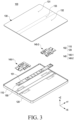
- FIG. 1 is a view illustrating an unfolded state of an electronic device according to various embodiments of the disclosure.
- FIG. 2 is a view illustrating a folded state of an electronic device according to various embodiments of the disclosure.
- an electronic device 100 may include a foldable housing 102 (hereinafter, simply referred to as a housing 102) for accommodating components (e.g., the hinge module 140) of the electronic device 100 and a flexible or foldable display 130 (hereinafter, simply referred to as a "display” 130) disposed in a space formed by the housing 102.
- a foldable housing 102 hereinafter, simply referred to as a housing 102
- components e.g., the hinge module 140
- a flexible or foldable display 130 hereinafter, simply referred to as a "display” 130
- the housing 102 may include a first housing 110, a second housing 120, and a hinge cover 150.
- the first housing 110 and/or the second housing 120 may form a portion of the exterior of the electronic device 100.
- the surface where the display 130 is visually exposed is defined as a front surface (e.g., a first front surface 110a and a second front surface 120a) of the electronic device 100 and/or housing 102.
- a surface opposite to the front surface is defined as a rear surface (e.g., a first rear surface 110b and a second rear surface 120b) of the electronic device 100.
- a surface surrounding at least a portion of the space between the front surface and the rear surface is defined as a side surface (e.g., the first side surface 110c and the second side surface 120c) of the electronic device 100.
- the first housing 110 may be rotated about the second housing 120 by a hinge module (e.g., the hinge module 140 of FIG. 3 ).
- the electronic device 100 may turn into a folded state (e.g., FIG. 2 ) or unfolded state (e.g., FIG. 1 ).
- the first front surface 110a may face the second front surface 120a and, in the unfolded state, the direction in which the first front surface 110a faces may be the same as the direction in which the second front surface 120a faces.
- the first front surface 110a may be positioned on substantially the same plane as the second front surface 120a.
- the first housing 110 and the second housing 120 are disposed on both sides of the folding axis A and be overall symmetrical in shape with respect to the folding axis A.
- the angle between the first housing 110 and the second housing 120 may be changed depending on whether the electronic device 100 is in the unfolded state, the folded state, or an intermediate state between the unfolded state and the folded state.
- the folding axis A may be a virtual axis positioned between (e.g., in the middle) between a first rotational axis (e.g., the first rotational axis Ax1 of FIG. 4 ) and a second rotational axis (e.g., the second rotational axis Ax2 of FIG. 4 ).
- the hinge cover 150 may be disposed between the first housing 110 and the second housing 120. According to an embodiment, the hinge cover 150 may be hidden by a portion of the first housing 110 and second housing 120 or be exposed to the outside depending on the state of the electronic device 100. According to an embodiment, the hinge cover 150 may protect the hinge module 140 from an external impact of the electronic device 100.
- the hinge cover 150 in the unfolded state of the electronic device 100, the hinge cover 150 may be hidden, and thus not exposed, by the first housing 110 and the second housing 120.
- the hinge cover 150 in the folded state (e.g., a fully folded state) of the electronic device 100, the hinge cover 150 may be exposed to the outside between the first housing 110 and the second housing 120.
- the hinge cover 150 in an intermediate state in which the first housing 110 and the second housing 120 are folded with a certain angle, the hinge cover 150 may be partially exposed to the outside between the first housing 110 and the second housing 120. In this case, however, the exposed area may be smaller than in the fully folded state.
- the hinge cover 150 may include a curved surface.
- the display 130 may mean a display at least a portion of which may be transformed into a flat or curved surface.
- the display 130 may include a folding area 133, a first display area 131 disposed on one side of the folding area 133 (e.g., the left side of the folding area 133 of FIG. 1 ), and a second display area 132 disposed on the opposite side of the folding area 133 (e.g., the right side of the folding area 203 of FIG. 1 ).
- the folding area 133 may be formed over the hinge module (e.g., the hinge module 140 of FIG. 3 ).
- the first display area 131 may be disposed on the first housing 110
- the second display area 132 may be disposed on the second housing 120.
- the display 130 may be accommodated in the first housing 110 and the second housing 120.
- the segmentation of the display 130 as shown in FIG. 1 is merely an example, and the display 130 may be divided into a plurality of (e.g., four or more, or two) areas depending on the structure or function of the display 200.
- the display 130 may be divided into the areas by the folding area 133 or folding axis (axis A) extending in parallel with the Y axis but, in another embodiment, the display 130 may be divided into the areas with respect to another folding area (e.g., a folding area parallel with the X axis) or another folding axis (e.g., a folding axis parallel with the X axis).
- the display 130 may be coupled with or disposed adjacent to a touch detection circuit, a pressure sensor capable of measuring the strength (pressure) of touches, and/or a digitizer for detecting a magnetic field-type stylus pen.
- the electronic device 100 may include a rear display 134.
- the rear display 134 may be disposed to face in a different direction from the display 130.
- the display 130 may be visually exposed through the front surface (e.g., the first front surface 110a and/or the second front surface 120a) of the electronic device 100, and the rear display 134 may be visually exposed through the rear surface (e.g., the first rear surface 110b) of the electronic device 100.
- the electronic device 100 may include at least one camera 104 and 106.
- the electronic device 100 may include a front camera 104 exposed through the front surface (e.g., the second front surface 120a) and/or a rear camera 106 exposed through the rear surface (e.g., the second rear surface 120b).
- the cameras 104 and 106 may include one or more lenses, an image sensor, a flash, and/or an image signal processor.
- the flash may include, e.g., a light emitting diode (LED) or a xenon lamp.
- two or more lenses an infrared (IR) camera, a wide-angle lens, and a telephoto lens
- image sensors may be disposed on one surface of the electronic device 100.
- FIG. 3 is a perspective view illustrating an electronic device according to various embodiments of the disclosure.
- FIG. 4 is a view illustrating a connected structure of a first housing and a second housing in an electronic device according to various embodiments of the disclosure.
- the electronic device 100 may include at least one hinge module 140 connecting the first housing 110 and the second housing 120.
- the configuration of the first housing 110, the second housing 120, the display 130, and the hinge cover 150 of FIGS. 3 and 4 may be identical in whole or part to the configuration of the first housing 110, the second housing 120, the display 130, and the hinge cover 150 of FIG. 1 and 2 .
- the first housing 110 and/or the second housing 120 may support components (e.g., the display 130, the hinge module 140, and the battery (not shown)) of the electronic device 100.
- components e.g., the display 130, the hinge module 140, and the battery (not shown) of the electronic device 100.
- the hinge module 140 may rotatably couple the second housing 120 to the first housing 110.
- the first housing 110 and/or the first display area 131 may rotate about the first rotational axis Ax1
- the second housing 120 and/or second display area 132 may rotate about the second rotational axis Ax2.
- the electronic device 100 may fold, allowing the first display area 131 and the second display area 132 to face each other. In the folded state, the electronic device 100 may be unfolded up to a designated angle.
- the "designated angle" may mean 180 degrees.
- the hinge module 140 may be disposed between the housing 102 and the display 130.
- the second rotational axis Ax2 may be disposed substantially parallel to the first rotational axis Ax 1.
- the hinge module 140 may include a rotating structure 200, an interlocking structure 300 and/or a fixing structure 400.
- the rotating structure 200 may substantially implement or guide rotation of the first housing 110 and/or the second housing 120.
- the rotating structure 200 may provide a first rotational axis Ax1 and a second rotational axis Ax2 formed in a recess (e.g., the first rotating space 231 and the second rotating space 232).
- the rotating structure 200 may be connected with the first housing 110 and the second housing 120.
- the first rotating member e.g., the first rotating member 210 of FIG. 5A
- the second rotating member e.g., the second rotating member 220 of FIG. 5A
- the interlocking structure 300 may interlock the rotation of the first housing 110 with the rotation of the second housing 120.
- the interlocking structure 300 may transfer at least a portion of the force applied to the first housing 110 to the second housing 120 or transfer at least a portion of the force applied to the second housing 120 to the first housing 110.
- the interlocking structure 300 may rotate the second housing 120 at substantially the same angle as the angle at which the first housing 110 is rotated, using a spiral rotating member (e.g., the first spiral rotating member 310 or second spiral rotating member 320 of FIG. 5A ).
- the interlocking structure 300 may be connected with the first housing 110 and the second housing 120.
- first spiral rotating member e.g., the first spiral rotating member 310 of FIG. 5A
- second spiral rotating member e.g., the second spiral rotating member 320 of FIG. 5A
- the fixing structure 400 may position the first housing 110 and the second housing 120 at a certain angle.
- the fixing structure 400 may provide pressure to the interlocking structure 300 to prevent or reduce movement and/or rotation of the first housing 110 and/or the second housing 120 of the electronic device 100.
- the hinge module 140 may allow the first housing 110 and/or the second housing 120 to rotate, and if no or less than the predetermined degree of external force is applied, the hinge module 140 may keep the first housing 110 and/or the second housing 120 stationary using the first fixing structure 400.
- the fixing structure 400 may be connected with the first housing 110 and the second housing 120.
- a first detent member (e.g., the first detent member 410 of FIG. 15A) of the fixing structure 400 may be connected or coupled with the first housing 110.
- a second detent member e.g., the second detent member 420 of FIG. 14B
- the second housing 120 may be connected or coupled with the second housing 120.
- the hinge module 140 may include a first hinge module 140-1 and a second hinge module 140 spaced apart in the length direction (e.g., the Y-axis direction) from the first hinge module 140-1.
- the hinge cover 150 may accommodate at least a portion of at least one hinge module 140.
- the hinge cover 150 may include an accommodating recess 151 for accommodating a slide member (e.g., the slide member 350 of FIG. 5A ) of the hinge module 140.
- a slide member e.g., the slide member 350 of FIG. 5A
- at least a portion of the hinge cover 150 may be positioned between the hinge module 140 and the housing 102.
- FIG. 5A is a perspective view illustrating a hinge module in an unfolded state according to various embodiments of the disclosure
- FIG. 5B is a perspective view illustrating a hinge module in a folded state according to various embodiments of the disclosure.
- FIG. 6A is a front view illustrating a hinge module in an unfolded state according to various embodiments of the disclosure
- FIG. 6B is a front view illustrating a hinge module in a folded state according to various embodiments of the disclosure.
- the hinge module 140 may include a plurality of components constituting the rotating structure 200, the interlocking structure 300, and the fixing structure 400.
- the configuration of the hinge module 140 of FIGS. 5A , 5B , 6A , and 6B may be identical in whole or part to the configuration of the hinge module 140 of FIGS. 3 and 4 .
- the rotating structure 200 may include a first rotating member 210, a second rotating member 220 and a rotating bracket 230.
- the first rotating member 210 may be connected to the first housing (e.g., the first housing 110 of FIG. 4 ).
- the second rotating member 220 may be connected to the second housing (e.g., the second housing 120 of FIG. 4 ).
- the rotating bracket 230 may be disposed in the accommodating recess 151 of the hinge cover 150.
- the rotating bracket 230 may accommodate the first rotating member 210 and the second rotating member 220.
- the rotating bracket 230 may include a rotating recess (e.g., the first rotating space 231 of FIG. 8 ) formed to rotate about the first rotational axis Ax1 and a rotating recess (e.g., the second rotating space 232 of FIG. 8 ) formed to rotate about the second rotational axis Ax2.
- the first rotating member 210 may be accommodated in the first rotating space 231 and rotate about the first rotational axis Ax1.
- the second rotating member 220 may be accommodated in the second rotating space 232 and rotate about the second rotational axis Ax2.
- the interlocking structure 300 may include a first spiral rotating member 310, a second spiral rotating member 320, and a slide member 350.
- the first spiral rotating member 310 may be connected to or coupled with the first housing (e.g., the first housing 110 of FIG. 4 ).
- the second spiral rotating member 320 may be connected to or coupled with the second housing (e.g., the second housing 120 of FIG. 4 ).
- the first spiral rotating member 310, along with the first housing 110 may rotate about the first rotational axis Ax1.
- the second spiral rotating member 320, along with the second housing 120 may rotate about the second rotational axis Ax2.
- the slide member 350 may not be directly coupled to the first housing 110 and/or the second housing 120.
- the slide member 350 may accommodate the first spiral rotating member 310 and the second spiral rotating member 320.
- the slide member 350 may include a first through hole 351 for accommodating at least a portion of the first spiral rotating member 310 and a second through hole 352 for accommodating at least a portion of the second spiral rotating member 320.
- the first spiral rotating member 310 may include a first bracket 311 connected with the first housing (e.g., the first housing 110 of FIG. 4 ) and a first spiral rotating bracket 312 extending from the first bracket 311 and configured to rotate in the first through hole 351.
- first bracket 311 connected with the first housing (e.g., the first housing 110 of FIG. 4 )
- first spiral rotating bracket 312 extending from the first bracket 311 and configured to rotate in the first through hole 351.
- the first spiral rotating bracket 312 in the unfolded state (e.g., FIG. 6A ) of the hinge module 140, the first spiral rotating bracket 312 may be positioned in the first through hole 351 and, in the folded state (e.g., FIG. 6B ) of the hinge module 140, at least a portion of the first spiral rotating bracket 312 may be exposed to the outside of the first through hole 351.
- the second spiral rotating member 320 may include a second bracket 321 connected with the second housing (e.g., the second housing 120 of FIG. 4 ) and a second spiral rotating bracket 322 extending from the second bracket 321 and configured to rotate in the second through hole 352.
- the second spiral rotating bracket 322 may be positioned in the second through hole 352 and, in the folded state (e.g., FIG. 6B ) of the hinge module 140, at least a portion of the second spiral rotating bracket 322 may be exposed to the outside of the second through hole 352.
- the interlocking structure 300 may include a first guide member 330 and a second guide member 340.
- the first guide member 330 may be connected to the first housing (e.g., the first housing 110 of FIG. 4 ).
- the second guide member 340 may be connected to the second housing (e.g., the second housing 120 of FIG. 4 ).
- the first guide member 330, along with the first housing 110 may rotate about the first rotational axis Ax1.
- the second guide member 340, along with the second housing 120 may rotate about the second rotational axis Ax2.
- the guide members 330 and 340 may prevent or reduce escape of the spiral rotating members 310 and 320 from the slide member 350.
- the first guide member 330 may surround at least a portion of the first spiral rotating member 310.
- the first spiral rotating bracket 312 of the first spiral rotating member 310 may be disposed between the first guide member 330 and the slide member 350.
- the second guide member 340 may surround at least a portion of the second spiral rotating member 320.
- the second spiral rotating bracket 322 of the second spiral rotating member 320 may be disposed between the second guide member 340 and the slide member 350.
- the first spiral rotating member 310, together with the first guide member 330 may rotate about the slide member 350.
- the second spiral rotating member 320, together with the second guide member 340 may rotate about the slide member 350.
- the slide member 350 may include a first area 355 facing the first spiral rotating member 310 and the first guide member 330 and a second area 356 facing the second spiral rotating member 320 and the second guide member 340.
- the first area 355 may include the first through hole 351.
- the second area 356 may include the second through hole 352.
- the slide member 350 may guide rotation of the first guide member 330 and the second guide member 340.
- the first area 355 of the slide member 350 may include a first recess 355-1 for accommodating the first guide member 330.
- the first recess 355-1 may be a cylindrical recess formed around the first rotational axis Ax1.
- the second area 356 of the slide member 350 may include a second recess 356-1 for accommodating the second guide member 340.
- the second recess 356-1 may be a cylindrical recess formed around the second rotational axis Ax2.
- the guide members 330 and 340 may be omitted.
- the hinge cover e.g., the hinge cover 150 of FIG. 3
- the first spiral rotating member 310 and the first guide member 330 may be integrally formed with each other.
- the second spiral rotating member 320 and the second guide member 340 may be integrally formed with each other.
- the interlocking structure 300 may be spaced apart from the rotating structure 200.
- the interlocking structure 300 may be spaced apart from the rotating structure 200 in a length direction (e.g., Y-axis direction).
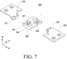
- FIG. 7 is an exploded perspective view illustrating a rotating structure according to various embodiments of the disclosure.
- the rotating structure 200 may include a first rotating member 210, a second rotating member 220 and a rotating bracket 230.
- the configuration of the first rotating member 210, the second rotating member 220, and the rotating bracket 230 of FIG. 7 may be identical in whole or part to the configuration of the first rotating member 210, the second rotating member 220, and the rotating bracket 230 of FIGS. 5A , 5B , 6A , and 6B .
- the rotating bracket 230 may include a first rotating space 231 and a second rotating space 232 separated from each other.
- the first rotating space 231 may be a space in which the first rotating member 210 is rotatably accommodated or positioned
- the second rotating space 232 may be a space in which the second rotating member 220 is rotatably accommodated or positioned.
- the first rotating space 231 may accommodate a portion (e.g., the first rotating rail 211) of the first rotating member 210 and may guide rotation of the first rotating member 210.
- the second rotating space 232 may accommodate a portion (e.g., the second rotating rail 221) of the second rotating member 220 and may guide rotation of the second rotating member 220.
- the first rotating space 231 may be spaced apart from the first rotational axis Ax1 by a designated distance.
- the second rotating space 232 may be spaced apart from the second rotational axis Ax2 by a designated distance.
- the first rotating member 210 may include a first rotating rail 211 extending to form a curved trajectory.
- the second rotating member 220 may include a second rotating rail 221 extending to form a curved trajectory.
- the first rotating rail 211 may be inserted in the first rotating space 231.
- the second rotating rail 221 may be inserted in the second rotating space 232.
- the center of the radius of curvature of the first rotating rail 211 may be positioned on the first rotational axis Ax1.
- the center of the radius of curvature of the second rotating rail 221 may be positioned on the second rotational axis Ax2.
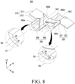
- FIG. 8 is a perspective view illustrating an interlocking structure according to various embodiments of the disclosure.
- the interlocking structure 300 may include a first spiral rotating member 310, a second spiral rotating member 320, and a slide member 350.
- the configuration of the first spiral rotating member 310, the second spiral rotating member 320, and the slide member 350 of FIG. 8 may be identical in whole or part to the configuration of the first spiral rotating member 310, the second spiral rotating member 320, and the slide member 350 of FIGS. 5A , 5B , 6A , and 6B .
- the slide member 350 may be formed in a structure for spirally rotating the first spiral rotating member 310 around the first rotational axis Ax1.
- at least a portion (e.g., the first area 355) of the slide member 350 may be a portion of a hollow cylinder shape formed around the first rotational axis Ax1.
- the slide member 350 may include a first area 355 that includes a first outer surface s1 spaced apart from the first rotational axis Ax1 by a first distance d1 and a first inner surface s2 spaced apart from the first rotational axis Ax1 by a second distance d2 shorter than the first distance d1.
- the slide member 350 may be formed in a structure for spirally rotating the second spiral rotating member 320 around the second rotational axis Ax2.
- at least a portion (e.g., the second area 356) of the slide member 350 may be a portion of a hollow cylinder shape formed around the second rotational axis Ax2.
- the slide member 350 may include a second area 356 that includes a second outer surface s3 spaced apart from the second rotational axis Ax2 by a first distance d3 and a second inner surface s42 spaced apart from the second rotational axis Ax2 by a second distance d4 shorter than the first distance d3.
- the slide member 350 may accommodate the first spiral rotating member 310 and the second spiral rotating member 320.
- the slide member 350 may include a first through hole (e.g., the first through hole 351 of FIG. 6B ) for accommodating the first spiral rotating bracket 312 of the first spiral rotating member 310 and a second through hole (e.g., the second through hole 352 of FIG. 6B ) for accommodating the second spiral rotating bracket 322 of the second spiral rotating member 320.
- the first through hole 351 may be a spiral through hole formed around the first rotational axis Ax1
- the second through hole 352 may be a spiral through hole formed around the second rotational axis Ax2.
- the first area 355 of the slide member 350 may include a first surface 350a forming at least a portion of the first through hole 351 and a second surface 350b forming at least a portion of the first through hole 351.
- the second surface 350b may be substantially parallel to the first surface 350a.
- the first through hole 351 may be a space between the first surface 350a and the second surface 350b.
- the first through hole 351 may be interpreted as a space surrounded by a virtual surface extending from the first outer surface s1, a virtual surface extending from the first inner surface s2, the first surface 350a, and the second surface 350b.
- the slide member 350 may include a third surface 350c forming at least a portion of the second through hole 352 and a fourth surface 350d forming at least a portion of the second through hole 352.
- the third surface 350c may be substantially parallel to the fourth surface 350d.
- the second through hole 352 may be a space between the third surface 350c and the fourth surface 350d.
- the second through hole 352 may be interpreted as a space surrounded by a virtual surface extending from the second outer surface s3, a virtual surface extending from the second inner surface s4, the third surface 350c, and the fourth surface 350d.
- the first spiral rotating member 310 and/or the second spiral rotating member 320 may rotate while being in surface contact with the slide member 350.
- the first spiral rotating member 310 may slide in the first through hole (e.g., the first through hole 351 of FIG. 6B ).
- the first spiral rotating member 310 may rotate about the first rotational axis Ax1 while being in contact with the first surface 350a and/or the second surface 350b.
- the second spiral rotating member 320 may slide in the second through hole (e.g., the second through hole 352 of FIG. 6B ).
- the second spiral rotating member 320 may rotate about the second rotational axis Ax2 while being in contact with the third surface 350c and/or the fourth surface 350d.
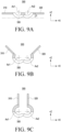
- FIGS. 9A, 9B, and 9C are side views illustrating a slide of an interlocking structure according to various embodiments of the disclosure.
- FIGS. 10A , 10B, and 10C are front views illustrating a slide of an interlocking structure according to various embodiments of the disclosure.
- an interlocking structure 300 may include a first spiral rotating member 310 spirally moving about the first rotational axis Ax1, a second spiral rotating member 320 spirally moving about the second rotational axis Ax2, and a slide member 350 accommodating the first spiral rotating member 310 and/or the second spiral rotating member 320.
- the configuration of the first spiral rotating member 310, the second spiral rotating member 320, and the slide member 350 of FIGS. 9A, 9B, 9C , 10A , 10B, and 10C may be identical in whole or part to the configuration of the first spiral rotating member 310, the second spiral rotating member 320, and the slide member 350 of FIG. 8 .
- the first spiral rotating member 310, the second spiral rotating member 320, and/or the slide member 350 may perform a spiral interlocking motion.
- the spiral interlocking motion may be interpreted as a motion in which rotation and linear (slide) motion are mutually converted.
- the first spiral rotating member 310 and/or the second spiral rotating member 320 may transfer a first force F1 to the first surface 350a, second surface 350b, third surface 350c, and/or fourth surface 350d of the slide member 350, and the first surface 350a, second surface 350b, third surface 350c, and/or fourth surface 350d of the slide member 350 may transfer a second force F2 to the first spiral rotating member 310 and/or the second spiral rotating member 320.
- the second force F2 may be a repulsive force of the first force F 1.
- the first force F1 and the second force F2 may be summed and be converted into a third force F3 acting on the first slide member 310, a fourth force F4 acting on the second slide member 320, and a fifth force F5 acting on the slide member 350.
- the sum of the third force F3 and the fourth force F4 may be substantially equal to the magnitude of the fifth force F5.
- the slide member 350 may slide in the length direction (e.g., the Y-axis direction) of the interlocking structure 300.
- the slide member 350 may be slid by the force (e.g., the fifth force F5) applied to the slide member 350 as the first spiral rotating member 310 connected to the first housing (e.g., the first housing 110 of FIG. 4 ) and/or the second spiral rotating member 320 connected to the second housing (e.g., the second housing 120 of FIG. 4 ) is rotated.
- the force e.g., the fifth force F5
- first spiral rotating member 310 and/or the second spiral rotating member 320 may be rotated by the force (e.g., the second force F2) applied to the first spiral rotating member 310 and/or the second spiral rotating member 320 as the slide member 350 slides (linear motion).
- the distance between the slide member 350 and the rotating structure e.g., the rotating structure 200 of FIG. 5A
- the distance between the slide member 350 and the rotating structure may be varied based on the angle between the first housing (e.g., the first housing 110 of FIG. 1 ) and the second housing (e.g., the second housing 120 of FIG. 2 ).
- the distance between the rotating structure 200 and the slide member 350 may be varied based on the angle between the first housing 110 and the second housing 120.
- the slide of the first spiral rotating member 310 and the second spiral rotating member 320 may be reduced or restricted.
- the first spiral rotating member 310 may be coupled to the first housing (e.g., the first housing 110 of FIG. 4 ) to restrict or reduce a motion in the length direction (e.g., Y-axis direction) of the first spiral rotating member 310
- the second spiral rotating member 320 may be coupled to the second housing (e.g., the second housing 120 of FIG. 4 ) to restrict or reduce a motion in the length direction (e.g., Y-axis direction) of the second spiral rotating member 320.
- the interlocking structure 300 may interlock without a gear by the first spiral rotating member 310, the second spiral rotating member 320, and the slide member 350.
- the thickness of the interlocking structure 300 may be thinner than the thickness of an interlocking structure (not shown) including a gear structure.
- the thickness t1 of the interlocking structure 300 may be 3.0 mm or less.
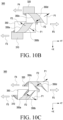
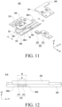
- FIG. 11 is an exploded perspective view illustrating an interlocking structure according to various embodiments of the disclosure.
- FIG. 12 is a cross-sectional view taken along line A-A' of FIG. 11 according to various embodiments of the disclosure.
- an interlocking structure 300 may include a first spiral rotating member 310, a second spiral rotating member 320, a first guide member 330, a second guide member 340, and a slide member 350.
- the configuration of the first spiral rotating member 310, the second spiral rotating member 320, the first guide member 330, the second guide member 340, and the slide member 350 of FIGS. 11 and 12 may be identical in whole or part to the configuration of the first spiral rotating member 310, the second spiral rotating member 320, the first guide member 330, the second guide member 340, and the slide member 350 of FIGS. 5A , 5B , 6A , and 6B .
- the first guide member 330 and/or the second guide member 340 may rotate together with the first spiral rotating member 310 and/or the second spiral rotating member 320.
- the first guide member 330, along with the first spiral rotating member 310 may rotate about a first rotational axis (e.g., the first rotational axis Ax1 of FIG. 6A ).
- the second guide member 340, along with the second spiral rotating member 320 may rotate around a second rotational axis (e.g., the second rotational axis Ax2 of FIG. 6A ).
- the first guide member 330 and/or the second guide member 340 may be accommodated in the slide member 350.
- the first guide member 330 may include at least one first protrusion 331 accommodated in a first recess 355-1 formed in the first area 355 of the slide member 350.
- the first protrusion 331 may face the first inner surface s2 of the slide member 350.
- the first protrusion 331 may be positioned on each of two opposite sides of a portion (e.g., the first spiral rotating bracket 312 of FIG. 6A ) of the first spiral rotating member 310.
- the first protrusion 331 may be positioned on one side of the first spiral rotating bracket 312.
- the first recess 355-1 may guide the rotation of the first guide member 330.
- the second guide member 340 may include at least one second protrusion 341 accommodated in the second recess 356-1 formed in the second area 356 of the slide member 350.
- the second protrusion 341 may face the second inner surface s4 of the slide member 350.
- the second protrusion 341 may be positioned on one side of the second spiral rotating bracket 322.
- the second protrusion 341 may be positioned on each of two opposite sides of a portion (e.g., the second spiral rotating bracket 322) of the second spiral rotating member 320.
- the second recess 356-1 may guide rotation of the second guide member 340.
- the interlocking structure 300 may be formed as a structure for preventing or reducing escape of the first spiral rotating member 310 or the second spiral rotating member 320 from the slide member 350.
- the first spiral rotating bracket 312 may include a first spiral rotating rail 313 facing the first guide member 330 and at least one first protruding area 314 extending from the first spiral rotating rail 313.
- the first protruding area 314 may protrude in the length direction (e.g., the Y-axis direction) of the interlocking structure 300.
- the second length l2 of the first protruding area 314 may be longer than the first length 11 of the first spiral rotating rail 313.
- the first protruding area 314 may face or contact jammed sides 350e and 350t of the slide member 350, preventing escape of the first slide member 310 from the slide member 350.
- the jammed sides 350e and 350t of the slide member 350 may be positioned between the first protruding area 314 and the first guide member 330.
- the interlocking structure 300 does not include the first guide member 330 and the second guide member 340, and the slide member 350 may slide with respect to a hinge cover (e.g., the hinge cover 150 of FIG. 3 ).
- the first spiral rotating rail 313 may face the hinge cover 150, and the first protruding area 314 may be positioned above the first spiral rotating rail 313 (e.g., in the +Z direction).
- the second spiral rotating bracket 322 may include a second spiral rotating rail (not shown) facing the second guide member 340 and a second protruding area (not shown) extending from the second spiral rotating rail.
- the configuration of the second spiral rotating rail and the second protruding area may be identical in whole or part to the configuration of the first spiral rotating rail 313 and the first protruding area 314.
- FIG. 13 is an exploded perspective view illustrating a hinge module and a hinge cover according to various embodiments of the disclosure.
- an electronic device 100 may include a hinge module 140 including a rotating structure 200, an interlocking structure 300, and a fixing structure 400 and a hinge cover 150.
- the configuration of the rotating structure 200, interlocking structure 300, fixing structure 400 and hinge cover 150 of FIG. 13 may be identical in whole or part to the configuration of the rotating structure 200, interlocking structure 300, fixing structure 400 and hinge cover 150 of FIG. 4 .
- the hinge cover 150 may guide the movement of the slide member 350.
- the hinge cover 150 may include an accommodating recess 151 for accommodating the slide member 350.
- the accommodating recess 151 may include a first accommodating recess 152 for accommodating a first area 355 of the slide member 350 and a second accommodating recess 153 for accommodating a second area 356 of the slide member 350.
- the first accommodating recess 152 and the second accommodating recess 153 may be symmetrical with respect to the length direction (e.g., Y-axis direction) of the electronic device 100.
- the slide member 350 may slide within the accommodating recess 151 of the hinge cover 150.
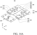
- FIG. 14A is a perspective view illustrating a hinge module in an unfolded state including a fixing structure according to various embodiments of the disclosure.
- FIG. 14B is a perspective view illustrating a hinge module in a folded state including a fixing structure according to various embodiments of the disclosure.
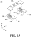
- FIG. 15 is an exploded perspective view illustrating a fixing structure according to various embodiments of the disclosure.
- a hinge module 140 may include a rotating structure 200, an interlocking structure 300, and a fixing structure 400.
- the configuration of the rotating structure 200, interlocking structure 300, and fixing structure 400 of FIGS. 14A , 14B , and 15 may be identical in whole or part to the configuration of the rotating structure 200, the interlocking structure 300, and the fixing structure 400 of FIG. 4 .
- the fixing structure 400 may include a first detent member 410 and a second detent member 420.
- the first detent member 410 may be connected to the first housing (e.g., the first housing 110 of FIG. 4 ) and may face at least a portion of the slide member 350, at least a portion of the first guide member 330, and/or at least a portion of the first spiral rotating member 310.
- the second detent member 420 may be connected to the second housing (e.g., the second housing 120 of FIG. 4 ) and may face at least a portion of the slide member 350, at least a portion of the second guide member 340, and/or at least a portion of the second spiral rotating member 320.
- the first detent member 410 and the second detent member 420 may surround at least a portion of the interlocking structure 300.
- the first detent member 410 and/or the second detent member 420 may provide pressure to the interlocking structure 300.
- the first detent member 410 may include at least one first cam structure 411, at least one first resilient member 412, and a first detent bracket 413.
- the first cam structure 411 may provide frictional force to the slide member 350.
- the first cam structure 411 may contact the slide member 350 to prevent or reduce the slide of the slide member 350.
- the first resilient member 412 may provide elastic force to the first cam structure 411.
- the first resilient member 412 may provide elastic force in the thickness direction (e.g., the Z-axis direction of FIG. 15 ) of the hinge module 140 to allow the first cam structure 411 to contact and face the slide member 350.
- the first resilient member 412 may be disposed between the first cam structure 411 and the first detent bracket 413.
- the first resilient member 412 may be a spring.
- the first detent bracket 413 may include a first detent bracket 413 connected to at least one first cam structure 411.
- the first detent bracket 413 may be connected to the first housing (e.g., the first housing 110 of FIG. 4 ).
- the first detent bracket 413, along with the first housing 110, may rotate around a first rotational axis (e.g., the first rotational axis Ax1 of FIG. 6A ).
- the second detent member 420 may include at least one second cam structure 421, at least one second resilient member 422, and a second detent bracket 423.
- the second detent member 420 is a component symmetrical to the first detent member 410 with respect to the folding axis (e.g., the folding axis A of FIG. 1 ), and the description of the first detent member 410, the first cam structure 411, the first resilient member 412, and the first detent bracket 413 may be applied to the configuration of the second detent member 420, the second cam structure 421, the second resilient member 422, and the second detent bracket 423.
- FIG. 16 is a front view illustrating a hinge module including a fixing structure according to various embodiments of the disclosure.
- FIG. 17 is a cross-sectional view taken along line B-B' of FIG. 16 according to various embodiments of the disclosure.
- FIG. 18 is a cross-sectional view taken along line C-C' of FIG. 16 according to various embodiments of the disclosure.
- FIGS. 19A and 19B are views illustrating an operation in which a hinge module is fixed according to various embodiments of the disclosure.
- the hinge module 140 may be adjusted for angle or position by the frictional force between a cam structure (e.g., the first cam structure 411) and the slide member 350.
- a cam structure e.g., the first cam structure 4111
- the configuration of the rotating structure 200, interlocking structure 300, and fixing structure 400 of FIGS. 16 to 18 may be identical in whole or part to the configuration of the rotating structure 200, the interlocking structure 300, and the fixing structure 400 of FIGS. 14A and 14B .
- the slide member 350 may include at least one third cam structure 357 configured to contact the at least one first cam structure 411.
- the third cam structure 357 may contact the first cam structure 411 based on the slide of the slide member 350.
- the first cam structure 411 may provide frictional force to the slide member 350.
- the first cam structure 411 may come into contact with the third cam structure 357 of the slide member 350 based on the slide of the slide member 350.
- the first cam structure 411 may accommodate at least one first resilient member 412 and/or the first detent bracket 413.
- the first cam structure 411 may include at least one first pin structure 411-1 protruding toward the first detent bracket 413.
- the first pin structure 411-1 may be connected to the first detent bracket 413.
- the first detent bracket 413 may be accommodated in the first cam structure 411.
- the first detent bracket 413 may include at least one second pin structure 413-1 protruding toward the first cam structure 411.
- the first resilient member 412 may be disposed to surround the first fin structure 411-1 and/or the second fin structure 413-1.
- the first cam structure 411 may include a first curved surface 411a to face the slide member 350.
- the first curved surface 411a of the first cam structure 411 may face the third cam structure 357 of the slide member 350 to provide force or pressure to the slide member 350.
- the description of the configuration of the first curved surface 411a of the first cam structure 411, the first pin structure 411-1 of the first cam structure 411, the first resilient member 412, and the second pin structure 413-1 of the first detent bracket 413 may be applied to the configuration of the second curved surface 421a of the second cam structure 421, the third cam structure 421-1 of the first cam structure 411, the second resilient member 422, and the fourth pin structure 423-1 of the second detent bracket 423.
- the third cam structure 357 may be interpreted as a structure including a valley portion and a mounting portion.
- the third cam structure 357 of the slide member 350 may include a first valley portion 357-1 and a first mounting portion 357-2.
- the first valley portion 357-1 and/or the second mounting portion 357-2 may be formed to correspond to the first cam structure 411 in the fully unfolded state (e.g., FIG. 19A ) of the electronic device (e.g., the electronic device 100 of FIG. 1 ) and/or the fully folded state (e.g., FIG. 2 ) of the electronic device 100.
- the unfolded state e.g., FIG.
- the first curved surface 411a of the first cam structure 411 may be formed in a shape corresponding to either the first valley portion 357-1 or the first mounting portion 357-2.
- an intermediate state e.g., FIG. 19B
- at least a portion of the first curved surface 411a of the first cam structure 411 may be spaced apart from the first valley portion 357-1 and/or the first mounting portion 357-2.
- the magnitude of the frictional force between the slide member 350 and the first cam structure 411 in the unfolded state may be larger than the magnitude of the frictional force between the slide member 350 and the first cam structure 411 in the intermediate state.
- the first detent member 410 including the first cam structure 411 may function as a free stop structure.
- the slide member 350 may include at least one fourth cam structure (not shown).
- the description of the configuration of the third cam structure 357 may be applied to the configuration of the fourth cam structure.
- the fourth cam structure may contact the second cam structure 421 of the second detent member 420 to generate frictional force.
- the hinge module 140 may interlock the motions of the first housing (e.g., the first housing 110 of FIG. 1 ) and the second housing (e.g., the second housing 120 of FIG. 2 ) using the spiral rotating members 310 and 320 and the slide member 350.
- the spiral rotating members 310 and 320 may rotate about the slide member 350 in a surface contact state. Since the spiral rotating members 310 and 320 come into surface contact with the slide member 350, the length of the spiral rotating members 310 and 320 for generating the required frictional force may be reduced.
- the third length 13 of the interlocking structure e.g., the interlocking structure 300 of FIG. 8
- the fourth length l4 of the hinge module 140 may be about 37.5 mm.
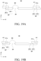
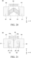
- FIG. 20 is a top view illustrating a hinge module according to one of various embodiments of the disclosure
- FIG. 21 is a rear view illustrating the hinge module of FIG. 20 .
- the hinge module 500 may include a first spiral rotating member 510, a second spiral rotating member 520, and a slide member 530.
- the hinge module 500 of FIGS. 20 and 21 may be identical in whole or part to the configuration of the hinge module 140 of FIG. 5A .
- the first spiral rotating member 510, the second spiral rotating member 520, and the slide member 530 of FIGS. 20 and 21 may be identical in whole or part to the configuration of the first spiral rotating member, the second spiral rotating member 320, and the slide member 350 of the interlocking structure 300 of FIG. 8 .
- the slide member 530 may accommodate the first spiral rotating member 510 and the second spiral rotating member 520.
- the slide member 530 may be slid in the length direction (e.g., Y-axis direction) of the hinge module 500 based on rotation of the first spiral rotating member 510 or the second spiral rotating member 520.
- the first spiral rotating member 510 may be formed in a substantially symmetrical shape with respect to the second spiral rotating member 520.
- the first spiral rotating member 510 and the second spiral rotating member 520 may be formed symmetrically with respect to the length direction (e.g., the Y-axis direction) of the hinge module 500.
- the slide member 350 may include a first through hole (e.g., the first through hole 351 of FIG. 6B ) and a second through hole (e.g., the second through hole 352 of FIG. 6B ) symmetrically formed with each other.
- the first spiral rotating member 510 and the second spiral rotating member 520 may be accommodated in the first through hole 351 and the second through hole 352, respectively.
- the length of the hinge module 500 in which the first spiral rotating member 510 and the second spiral rotating member 520 are formed symmetrically may be shorter than the length of a hinge module (e.g., the hinge module 140 of FIG. 5A ) in which they are asymmetrically formed.
- the first spiral rotating member 510 may include a first bracket 511 connected to the first housing (e.g., the first housing 110 of FIG. 1 ) and a first spiral rotating bracket 512 extending from the first bracket 511 and configured to rotate in the slide member 530.
- the first spiral rotating bracket 512 may include a first spiral rotating rail 513 positioned in a through hole (e.g., the first through hole 351 of FIG. 6B ) of the slide member 350 and at least one first protruding area 514 extending from the first spiral rotating rail 513.
- the configuration of the first bracket 511, the first spiral rotating bracket 512, the first spiral rotating rail 513, and the first protruding area 514 of FIG. 20 and/or 21 may be identical in whole or part to the configuration of the first bracket 311, the first spiral rotating bracket 312, the first spiral rotating rail 313, and the first protruding area 314 of FIG. 8 and/or 12.
- the second spiral rotating member 520 may include a second bracket 521 connected to the second housing (e.g., the second housing 120 of FIG. 1 ) and a second spiral rotating bracket 522 extending from the second bracket 521 and configured to rotate in the slide member 530.
- the second spiral rotating bracket 522 may include a second spiral rotating rail 523 positioned in a through hole (e.g., the second through hole 352 of FIG. 6B ) of the slide member 530 and at least one second protruding area 524 extending from the second spiral rotating rail 523.
- the configuration of the second bracket 521, the second spiral rotating bracket 522, the second spiral rotating rail 523, and the second protruding area 524 of FIG. 20 and/or 21 may be identical in whole or part to the configuration of the first bracket 511, the first spiral rotating bracket 512, the first spiral rotating rail 513, and the first protruding area 514.
- the hinge module 500 may include a guide member (e.g., 330 or 340 of FIG. 14A ).
- the guide members 330 and 340 may surround at least a portion of the first spiral rotating member 510 or at least a portion of the second spiral rotating member 520 and, along with the first spiral rotating member 510 and the second spiral rotating member 520, rotate about the slide member 530.
- the hinge module 500 may include a fixing structure (e.g., the fixing structure 400 of FIG. 14A ).
- a fixing structure e.g., the fixing structure 400 of FIG. 14A
- the first detent member e.g., the first detent member 410 of FIG. 14A
- the second detent member e.g., the second detent member 420 of FIG. 14A
- the slide member 530 may accommodate pressure transferred by the detent members 410 and 420, preventing or reducing a slide.
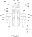
- FIG. 22 is an exploded perspective view illustrating a hinge module according to one of various embodiments of the disclosure.
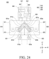
- FIG. 23 is a top view illustrating a hinge module according to one of various embodiments of the disclosure;
- FIG. 24 is a rear view illustrating the hinge module of FIG. 23 in an unfolded state.
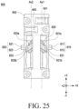
- FIG. 25 is a rear view illustrating the hinge module of FIG. 23 in a folded state.
- a hinge module 600 may include a first spiral rotating member 610, a second spiral rotating member 620, a slide member 630, and/or a hinge bracket 640.
- the configuration of the hinge module 600, the first spiral rotating member 610, and the second spiral rotating member 620 of FIG. 22 , 23 , 24 , and/or 25 may be identical in whole or part to the configuration of the hinge module 140, the first spiral rotating member 310 and the second spiral rotating member 320 of FIG. 5A .
- the first spiral rotating member 610 and/or the second spiral rotating member 620 may accommodate at least a portion of the slide member 630.
- the first spiral rotating member 610 may surround at least a portion (e.g., the first slide area 631) of the slide member 630.
- the second spiral rotating member 620 may surround at least a portion (e.g., the second slide area 633) of the slide member 630.
- the first spiral rotating member 610 and/or may guide the slide member 630.
- the first spiral rotating member 610 may include a fifth surface 611a facing the first slide area 631 and a sixth surface 613a facing the first slide area 631 and substantially parallel to the fifth surface 611a.
- the second spiral rotating member 620 may include a seventh surface 621a facing the second slide area 633 and an eighth surface 623a facing the second slide area 633 and substantially parallel to the seventh surface 621a.
- an empty space between the fifth surface 611a and the sixth surface 613a may have substantially the same configuration as the through hole (e.g., the first through hole 351 of FIG. 6B ).
- the configuration of the first spiral rotating member 610 may be identical in whole or part to the configuration of the first area 355 of the slide member 350 of FIG. 8
- the fifth surface 611a and/or the sixth surface 613a may be a spiral surface formed around the first rotational axis Ax1.
- the first spiral rotating member 610 may rotate in a state of being in surface contact with the slide member 630 by the fifth surface 611a and the sixth surface 613a.
- the first spiral rotating member 610 may be connected to the first housing (e.g., the first housing 110 of FIG. 1 ).
- the first spiral rotating member 610 may rotate about the first rotational axis Ax1 while being connected to the first housing 110.
- an empty space between the seventh surface 621a and the eighth surface 623a may have substantially the same configuration as the through hole (e.g., the second through hole 352 of FIG. 6B ).
- the configuration of the second spiral rotating member 620 may be identical in whole or part to the configuration of the second area 356 of the slide member 350 of FIG. 8
- the seventh surface 621a and/or the eighth surface 623a may be a spiral surface formed around the second rotational axis Ax2.
- the second spiral rotating member 620 may rotate in a state of being in surface contact with the slide member 630 by the seventh surface 621a and the eighth surface 623a.
- the second spiral rotating member 620 may be connected to the second housing (e.g., the second housing 120 of FIG. 1 ).
- the second spiral rotating member 620 may rotate about the second rotational axis Ax1 while being connected to the second housing 120.
- the first spiral rotating member 610 may be composed of a plurality of components.
- the first spiral rotating member 610 may include a 1-1th spiral rotating member 611 and a 1-2th spiral rotating member 613 to be fastened with the 1-1th spiral rotating member 611.
- the 1-1th spiral rotating member 611 may include the fifth surface 611a.
- the 1-2th spiral rotating member 613 may include the sixth surface 613a.
- at least a portion of the 1-1th spiral rotating member 611 may face a portion (e.g., the 3-1th spiral rotating rail 631a) of the first slide area 631.
- the 1-1th spiral rotating member 611 may include a first fastening area 611b.
- the 1-2th spiral rotating member 613 may include a second fastening area 613b that may be connected to the first fastening area 611b.
- the second fastening area 613b may be formed as a through hole or recess structure.
- the first fastening area 611b may be inserted into the second fastening area 613b.
- the first fastening area 611b may include a through hole or recess structure to reduce the weight and/or volume of the hinge module 600.
- the first fastening area 611b may be formed as a through hole or recess structure.
- the second fastening area 613b may be inserted into the first fastening area 611b.
- the second fastening area 613b may include a through hole or recess structure to reduce the weight and/or volume of the hinge module 600.
- the second spiral rotating member 620 may be composed of a plurality of components.
- the second spiral rotating member 620 may include a 2-1th spiral rotating member 621 and a 2-2th spiral rotating member 623 to be fastened with the 2-1th spiral rotating member 621.
- the 2-1th spiral rotating member 621 may include the seventh surface 621a.
- the 2-2th spiral rotating member 623 may include the eighth surface 623a.
- at least a portion of the 2-1th spiral rotating member 621 may face a portion (e.g., the 4-1th spiral rotating rail 633a) of the second slide area 633.
- the 2-1th spiral rotating member 621 may include a third fastening area 621b.
- the 2-2th spiral rotating member 623 may include a fourth fastening area 623b that may be connected to the third fastening area 621b.
- the fourth fastening area 623b may be formed as a through hole or recess structure.
- the third fastening area 621b may be inserted into the fourth fastening area 613b.
- the third fastening area 621b may include a through hole or recess structure to reduce the weight and/or volume of the hinge module 600.
- the third fastening area 621b may be formed as a through hole or recess structure.
- the fourth fastening area 623b may be inserted into the third fastening area 621b.
- the fourth fastening area 623b may include a through hole or recess structure to reduce the weight and/or volume of the hinge module 600.
- the assembly and/or processing convenience of the hinge module 600 in which the first spiral rotating member 610 and/or the second spiral rotating member 620 includes a plurality of components may be further increased than the assembly and/or processing convenience of the hinge module using one first spiral rotating member 610 and/or one second spiral rotating member 620.
- the slide member 630 may include a first slide area 631 connected to the first spiral rotating member 610 and a second slide area 633 connected to the second spiral rotating member 620.
- the first slide area 631 may be disposed between the 1-1th spiral rotating member 611 and the 1-2th spiral rotating member 613.
- the first slide area 631 may include a 3-1th spiral rotating rail 631a facing the 1-1th spiral rotating member 611 and a 3-2th spiral rotating rail 631b facing the 1-2th spiral rotating member 621.
- the second slide area 633 may be disposed between the 2-1th spiral rotating member 621 and the 2-2th spiral rotating member 623.
- the second slide area 633 may include a 4-1th spiral rotating rail 633a facing the 2-1st spiral rotating member 621 and a 4-2th spiral rotating rail 633b facing the 2-2th spiral rotating member 623.
- the slide member 630 may slide based on the movement of the first spiral rotating member 610 and/or the second spiral rotating member 620.
- the slide member 630 may include third spiral rotating rails 631a and 631b and/or fourth spiral rotating rails 633a and 633b extending in a curved trajectory.
- force or pressure may be provided to the third spiral rotating rails 631a and 631b of the first slide area 631 as the first spiral rotating member 610 rotates.
- force or pressure may be provided to the fourth spiral rotating rails 633a and 633b of the second slide area 633.
- the third spiral rotating rails 631a and 631b may face the first spiral rotating member 610.
- the third spiral rotating rails 631a and 631b may include a 3-1th spiral rotating rail 631a configured to slide based on the rotation of the fifth surface 611a of the 1-1th spiral rotating member 611 and a 3-2th spiral rotating rail 631b configured to slide based on the rotation of the sixth surface 613a of the 1-2th spiral rotating member 613.
- the 3-1th spiral rotating rail 631a may be formed to be substantially parallel to the 3-2th spiral rotating rail 631b.
- the fourth spiral rotating rails 633a and 633b may face the second spiral rotating member 620.
- the fourth spiral rotating rails 633a and 633b may include a 4-1th spiral rotating rail 633a configured to slide based on the rotation of the seventh surface 621a of the 2-1st spiral rotating member 621 and a 4-2th spiral rotating rail 633b configured to slide based on the rotation of the eighth surface 623a of the 2-2th spiral rotating member 623.
- the 4-1th spiral rotating rail 633a may be formed to be substantially parallel to the 4-2th spiral rotating rail 633b.
- the hinge bracket 640 may accommodate a first rotating member (e.g., the first rotating member 210 of FIG. 6A ) and/or a second rotating member (e.g., the second rotating member 620 of FIG. 6A ).
- the hinge bracket 640 may include a first rotating space 641 in which the first rotating member 210 is rotatably accommodated or positioned and a second rotating space 643 in which the second rotating member 220 is rotatably accommodated or positioned.
- the configuration of the hinge bracket 640 of FIGS. 23 to 25 may be identical in whole or part to the configuration of the rotation bracket 230 of FIG. 6A .
- the configuration of the first rotating space 641 and the second rotating space 643 of FIGS. 23 to 25 may be identical in whole or part to the configuration of the first rotating space 231 and the second rotating space 232 of FIG. 7 .
- the hinge bracket 640 may accommodate at least a portion of the interlocking structure 602.
- the interlocking structure 602 may include a first spiral rotating member 610, a second spiral rotating member 620, and a slide member 630.
- the hinge bracket 640 may include an accommodating space 645 in which the interlocking structure 602 is rotatably or slidably accommodated.
- the accommodating space 645 may include a third rotating space 645a for accommodating at least a portion of the first spiral rotating member 610, a fourth rotating space 645b for accommodating at least a portion of the second spiral rotating member 620, and an accommodating space 645c for accommodating at least a portion of the slide member 630.
- the accommodating space 645c may be positioned between the third rotating space 645a and the fourth rotating space 645b.
- the third rotating space 645a, the fourth rotating space 645b, and/or the accommodating space 645c may be formed in a shape of a recess or a through hole.
- the third rotating space 645a, the fourth rotating space 645b, and the accommodating space 645c may be one empty space.
- the first spiral rotating member 610 may rotate about the hinge bracket 640 with respect to the first rotational axis Ax1 in the third rotating space 645a.
- the second spiral rotating member 620 may rotate about the hinge bracket 640 with respect to the second rotational axis Ax2 in the fourth rotating space 645b.
- the slide member 630 may slide with respect to the hinge bracket 640 in a direction (e.g., Y-axis direction) substantially parallel to the first rotational axis Ax1 or the second rotational axis Ax2 in the accommodating space 645c.
- the hinge module 600 may include a guide member (e.g., 330 or 340 of FIG. 14A ).
- the guide members 330 and 340 may surround at least a portion of the first spiral rotating member 610 or at least a portion of the second spiral rotating member 620 and, along with the first spiral rotating member 610 and the second spiral rotating member 620, rotate about the slide member 630.
- the hinge module 600 may include a fixing structure (e.g., the fixing structure 400 of FIG. 14A ).
- a fixing structure e.g., the fixing structure 400 of FIG. 14A
- the first detent member e.g., the first detent member 410 of FIG. 14A
- the second detent member e.g., the second detent member 420 of FIG. 14A
- the slide member 630 may accommodate pressure transferred by the detent members 410 and 420, preventing or reducing a slide.
- an electronic device may comprise a first housing (e.g., the first housing 110 of FIG. 1 ), a second housing (e.g., the second housing 120 of FIG. 2 ), a display (e.g., the display 130 of FIG. 1 ) accommodated in the first housing and the second housing, and a hinge module (e.g., the hinge module 140 of FIG. 3 ) connecting the first housing and the second housing.
- the hinge module may include a rotating structure (e.g., the rotating structure 200 of FIG. 5A ) including a first rotating member (e.g., the first rotating member 210 of FIG.
- a second rotating member e.g., the second rotating member 220 of FIG. 5A
- a rotating bracket e.g., the rotating bracket 230 of FIG. 5A
- accommodating the first rotating member and the second rotating member and an interlocking structure e.g., the interlocking structure 300 of FIG. 5A
- an interlocking structure e.g., the interlocking structure 300 of FIG. 5A
- a first spiral rotating member e.g., the first spiral rotating member 310 of FIG. 5A
- a second spiral rotating member e.g., the second spiral rotating member 320 of FIG. 5A
- a first guide member e.g., the first guide member 330 of FIG.
- a second guide member e.g., the second guide member 340 of FIG. 5A
- a slide member e.g., the slide member 350 of FIG. 6A
- a first through hole e.g., the first through hole 351 of FIG. 6B
- a second through hole e.g., the second through hole 352 of FIG. 6B
- the slide member may include a first surface (e.g., the first surface 350a of FIG. 8 ) forming at least a portion of the first through hole, a second surface (e.g., the second surface 350b of FIG. 8 ) forming at least a portion of the first through hole and substantially parallel to the first surface, a third surface (e.g., the third surface 350c of FIG. 8 ) forming at least a portion of the second through hole, and a fourth surface (e.g., the fourth surface 350d of FIG. 8 ) forming at least a portion of the second through hole and substantially parallel to the third surface.
- a first surface e.g., the first surface 350a of FIG. 8
- a second surface e.g., the second surface 350b of FIG. 8
- a third surface e.g., the third surface 350c of FIG. 8
- a fourth surface e.g., the fourth surface 350d of FIG. 8
- the rotating bracket may include a first rotating space (e.g., the first rotating space 231 of FIG. 7 ) for accommodating the first rotating member and providing a first rotational axis (e.g., the first rotational axis Ax1 of FIG. 4 ) and a second rotating space (e.g., the second rotating space 232 of FIG. 7 ) for accommodating the second rotating member and providing a second rotational axis (e.g., the first rotational axis Ax1 of FIG. 4 ) substantially parallel to the first rotational axis.
- a first rotating space e.g., the first rotating space 231 of FIG. 7
- a second rotating space e.g., the second rotating space 232 of FIG. 7
- the slide member may include a first area (e.g., the first area 355 of FIG. 8 ) including a first outer surface (e.g., the first outer surface s1 of FIG. 8 ) spaced apart from the first rotational axis by a first distance (e.g., the first distance d1 of FIG. 8 ) and a first inner surface (e.g., the first surface s2 of FIG. 8 ) spaced apart from the second rotational axis by a second distance (e.g., the second distance d2 of FIG. 8 ) shorter than the first distance and a second area (e.g., the second area 356 of FIG.
- a first area e.g., the first area 355 of FIG. 8
- a first outer surface e.g., the first outer surface s1 of FIG. 8
- a first inner surface e.g., the first surface s2 of FIG. 8
- the hinge module may include a fixing structure (e.g., the fixing structure 400 of FIG. 14A ) including a first detent member (e.g., the first detent member 410 of FIG. 14A ) connected to the first housing and facing at least a portion of the slide member and at least a portion of the first guide member and a second detent member (e.g., the second detent member 420 of FIG. 14A ) connected to the second housing and facing at least a portion of the slide member and at least a portion of the second guide member.
- a fixing structure e.g., the fixing structure 400 of FIG. 14A
- a first detent member e.g., the first detent member 410 of FIG. 14A
- a second detent member e.g., the second detent member 420 of FIG. 14A
- the first detent member may include at least one first cam structure (e.g., the first cam structure 411 of FIG. 14A ) configured to provide a frictional force to the slide member, at least one first resilient member (e.g., the first resilient member 412 of FIG. 14A ) for providing an elastic force to the at least one first cam structure, and a first detent bracket (e.g., the first detent bracket 413 of FIG. 14A ) connected with the at least one first cam structure, and the second detent member may include at least one second cam structure (e.g., the second cam structure 421 of FIG.
- first cam structure e.g., the first cam structure 411 of FIG. 14A
- first resilient member e.g., the first resilient member 412 of FIG. 14A
- a first detent bracket e.g., the first detent bracket 413 of FIG. 14A
- the slide member 14A configured to provide a frictional force to the slide member, at least one second resilient member (e.g., the second resilient member 422 of FIG. 14A ) for providing an elastic force to the at least one second cam structure, and a second detent bracket (e.g., the second detent bracket 423 of FIG. 14A ) connected with the at least one second cam structure.
- at least one second resilient member e.g., the second resilient member 422 of FIG. 14A
- a second detent bracket e.g., the second detent bracket 423 of FIG. 14A
- the slide member may include at least one third cam structure (e.g., the third cam structure 357 of FIG. 18 ) configured to contact the at least one first cam structure and at least one fourth cam structure (not shown) configured to contact the at least one second cam structure.
- at least one third cam structure e.g., the third cam structure 357 of FIG. 18
- at least one fourth cam structure not shown
- the first spiral rotating member may include a first bracket (e.g., the first bracket 311 of FIG. 8 ) connected with the first housing and a first spiral rotating bracket (e.g., the first spiral rotating bracket 312 of FIG. 8 ) extending from the first bracket and configured to rotate in the first through hole
- the second spiral rotating member may include a second bracket (e.g., the second bracket 321 of FIG. 8 ) connected with the second housing and a second spiral rotating bracket (e.g., the second spiral rotating bracket 322 of FIG. 8 ) extending from the second bracket and configured to rotate in the second through hole.
- the first spiral rotating bracket may include a first spiral rotating rail (e.g., the first spiral rotating rail 313 of FIG. 12 ) facing the first guide member and a first protruding area (e.g., the first protruding area 314 of FIG. 12 ) extending from the first spiral rotating rail
- the second spiral rotating bracket may include a second spiral rotating rail facing the second guide member and a second protruding area extending from the second spiral rotating rail.
- the first spiral rotating bracket may be disposed between the first guide member and the slide member, and the second spiral rotating bracket may be disposed between the second guide member and the slide member.
- the electronic device may further comprise a hinge cover (e.g., the hinge cover 150 of FIG. 4 ) connected with the rotating structure and configured to guide a movement of the slide member.
- a hinge cover e.g., the hinge cover 150 of FIG. 4
- the hinge cover may include an accommodating recess (e.g., the accommodating recess 151 of FIG. 3 ) for accommodating the slide member.
- an accommodating recess e.g., the accommodating recess 151 of FIG. 3
- the slide member may include a first recess (e.g., the first recess 355-1 of FIG. 5A ) for guiding rotation of the first guide member and a second recess (e.g., the second recess 356-1 of FIG. 5B ) for guiding rotation of the second guide member.
- a first recess e.g., the first recess 355-1 of FIG. 5A
- a second recess e.g., the second recess 356-1 of FIG. 5B
- the first guide member may include at least one first protrusion (e.g., the first protrusion 331 of FIG. 11 ) facing the first rotating member and accommodated in the first recess
- the second guide member may include at least one second protrusion (e.g., the second protrusion 341 of FIG. 11 ) facing the second rotating member and accommodated in the second recess.
- a distance between the slide member and the rotating structure may be configured to be varied based on an angle between the first housing and the second housing.
- At least a portion of the first spiral rotating member may be configured to rotate with respect to the slide member along with the first guide member, and at least a portion of the second spiral rotating member may be configured to rotate with respect to the slide member along with the second guide member.
- an electronic device may comprise a first housing (e.g., the first housing 110 of FIG. 1 ), a second housing (e.g., the second housing 120 of FIG. 2 ), a display (e.g., the display 130 of FIG. 1 ) accommodated in the first housing and the second housing, a hinge module (e.g., the hinge module 140 of FIG. 3 ) connecting the first housing and the second housing, and a hinge cover disposed between the housing and the hinge module.
- the hinge module may include a rotating structure (e.g., the rotating structure 200 of FIG. 5A ) accommodating a first rotating member (e.g., the first rotating member 210 of FIG.
- a second rotating member e.g., the second rotating member 220 of FIG. 5A
- a rotating bracket e.g., the rotating bracket 230 of FIG. 5A
- accommodating the first rotating member and the second rotating member and an interlocking structure e.g., the interlocking structure 300 of FIG. 5A
- an interlocking structure e.g., the interlocking structure 300 of FIG. 5A
- a first spiral rotating member e.g., the first spiral rotating member 310 of FIG. 5A
- a second spiral rotating member e.g., the second spiral rotating member 320 of FIG. 5A
- a slide member e.g., the slide member 350 of FIG.
- the hinge cover may be configured to guide a slide of the slide member.
- the slide member may include a first surface (e.g., the first surface 350a of FIG. 8 ) forming at least a portion of the first through hole, a second surface (e.g., the second surface 350b of FIG. 8 ) forming at least a portion of the first through hole and substantially parallel to the first surface, a third surface (e.g., the third surface 350c of FIG. 8 ) forming at least a portion of the second through hole, and a fourth surface (e.g., the fourth surface 350d of FIG. 8 ) forming at least a portion of the second through hole and substantially parallel to the third surface.
- a first surface e.g., the first surface 350a of FIG. 8
- a second surface e.g., the second surface 350b of FIG. 8
- a third surface e.g., the third surface 350c of FIG. 8
- a fourth surface e.g., the fourth surface 350d of FIG. 8
- the rotating bracket may include a first rotating space (e.g., the first rotating space 231 of FIG. 7 ) for accommodating the first rotating member and providing a first rotational axis (e.g., the first rotational axis Ax1 of FIG. 7 ) and a second rotating space (e.g., the second rotating space 232 of FIG. 7 ) for accommodating the second rotating member and providing a second rotational axis (e.g., the second rotational axis Ax2 of FIG. 7 ) substantially parallel to the first rotational axis.
- the slide member may include a first area (e.g., the first area 355) including a first outer surface (e.g., the first surface s1 of FIG.
- first distance e.g., the first distance d1 of FIG. 8
- first inner surface e.g., the first inner surface s2 of FIG. 8
- second distance e.g., the second distance d2 of FIG. 8
- second area e.g., the second area 356
- second outer surface e.g., the second outer surface s3 of FIG. 8
- second inner surface e.g., the second inner surface s4 of FIG. 8
- the slide member may include a first area (e.g., the first area 355 of FIG. 11 ) including the first through hole and a second area (e.g., the second area 356 of FIG. 11 ) extending from the first area and including the second through hole.
- the hinge cover may include an accommodating recess (e.g., the accommodating recess 151 of FIG. 3 ) for accommodating the first area and the second area.
- the hinge module may include a fixing structure (e.g., the fixing structure 400 of FIG. 14A ) including a first detent member (e.g., the first detent member 410 of FIG. 13 ) connected to the first housing and facing at least a portion of the slide member and a second detent member (e.g., the second detent member 420 of FIG. 13 ) connected to the second housing and facing at least a portion of the slide member.
- a fixing structure e.g., the fixing structure 400 of FIG. 14A
- a first detent member e.g., the first detent member 410 of FIG. 13
- a second detent member e.g., the second detent member 420 of FIG. 13
- an electronic device may comprise a first housing (e.g., the first housing 110 of FIG. 1 ), a second housing (e.g., the second housing 120 of FIG. 1 ), a display (e.g., the display 130 of FIG. 1 ) accommodated in the first housing and the second housing, and a hinge module (e.g., the hinge module 600 of FIG. 23 ) connecting the first housing and the second housing.
- the hinge module may include a rotating structure (e.g., the rotating structure 200 of FIG. 7 ) including a first rotating member (e.g., the first rotating member 210 of FIG.
- an interlocking structure e.g., the interlocking structure 602 of FIG. 23
- a first spiral rotating member e.g., the first spiral rotating member 610 of FIG. 22
- a second spiral rotating member e.g., the second spiral rotating member 620 of FIG. 22
- a slide member e.g., the slide member 630 of FIG. 22
- a first slide area e.g., the first slide area 631 of FIG.
- a hinge bracket e.g., the hinge bracket 640 of FIG. 23
- a first rotating space e.g., the first rotating space 641 of FIG. 23
- a second rotating space e.g., the second rotating space 643 of FIG.
- the second rotating member for accommodating the second rotating member and providing a second rotational axis (e.g., the second rotational axis Ax2 of FIG. 23 ), and an accommodating space (e.g., the accommodating space 645 of FIG. 23 ) for accommodating the interlocking structure.
- a second rotational axis e.g., the second rotational axis Ax2 of FIG. 23
- an accommodating space e.g., the accommodating space 645 of FIG. 23
- the first spiral rotating member may include a fifth surface (e.g., the fifth surface 611a of FIG. 23 ) facing the first slide area and a sixth surface (e.g., the sixth surface 613a of FIG. 23 ) facing the first slide area and substantially parallel to the first surface
- the second spiral rotating member may include a seventh surface (e.g., the seventh surface 621a of FIG. 23 ) facing the second slide area and an eighth surface (e.g., the eighth surface 623a of FIG. 23 ) facing the second slide area and substantially parallel to the seventh surface.
- the first spiral rotating member may include a 1-1th spiral rotating member (e.g., the first spiral rotating member 610 of FIG. 22 ) including the fifth surface and a 1-2th spiral rotating member (e.g., the 1-2th spiral rotating member 613 of FIG. 22 ) connected with the 1-1th spiral rotating member and including the sixth surface
- the second spiral rotating member may include a 2-1th spiral rotating member (e.g., the 2-1th spiral rotating member 621 of FIG. 22 ) including the seventh surface and a 2-2th spiral rotating member (e.g., the 2-2th spiral rotating member 623 of FIG. 22 ) connected with the 2-1th spiral rotating member and including the eighth surface.
- the first slide area may include a third spiral rotating rail (e.g., the 3-1th spiral rotating rail 631a and the 3-2th spiral rotating rail 631b of FIG. 22 ) facing the first spiral rotating member
- the second slide area may include a fourth spiral rotating rail (e.g., the 4-1th spiral rotating rail 633a and the 4-2th spiral rotating rail 633b of FIG. 22 ) facing the second spiral rotating member.
Abstract
Description
- Various embodiments of the disclosure relate to an electronic device including a hinge module.
- With the development of information and communication technology and semiconductor technology, various functions are being integrated into one portable electronic device. For example, an electronic device may implement not only communication functions but also entertainment functions, such as playing games, multimedia functions, such as playing music and videos, communication and security functions for mobile banking, and scheduling and e-wallet functions. Such electronic devices become compact enough for users to carry in a convenient way.
- As mobile communication services extend up to multimedia service sectors, electronic devices require a larger display to allow users satisfactory use of multimedia services as well as voice call or text messaging services. This, however, trades off the trend of electronic devices being compact.
- An electronic device (e.g., a portable terminal) includes a display having a flat surface or both a flat surface and a curved surface. An electronic device including a display may have a limitation in realizing a screen larger than the size of the electronic device due to the fixed display structure. Accordingly, research has been conducted on electronic devices including a foldable or rollable display.
- In implementing a foldable electronic device, it may be difficult to secure mechanical stability while enabling structures of the electronic device to move relative to one another (e.g., slide, rotate, or pivot). For example, it may be hard to secure a stable operation structure while securing or maintaining portability by downsizing or sliming down foldable electronic devices.
- According to various embodiments of the disclosure, there may be provided an electronic device including a hinge module capable of stably implementing the folding or unfolding of housings.
- The disclosure is not limited to the foregoing embodiments but various modifications or changes may rather be made thereto without departing from the spirit and scope of the disclosure.
- According to various embodiments of the disclosure, an electronic device may comprise a first housing, a second housing, a display accommodated in the first housing and the second housing, and a hinge module connecting the first housing and the second housing. The hinge module may include a rotating structure including a first rotating member connected with the first housing, a second rotating member connected with the second housing, and a rotating bracket accommodating the first rotating member and the second rotating member and an interlocking structure including a first spiral rotating member connected with the first housing, a second spiral rotating member connected with the second housing, a first guide member connected with the first housing and surrounding at least a portion of the first spiral rotating member, a second guide member connected with the second housing and surrounding at least a portion of the second spiral rotating member, and a slide member including a first through hole for accommodating at least a portion of the first spiral rotating member and a second through hole for accommodating at least a portion of the second spiral rotating member and configured to slide based on a motion of the first spiral rotating member or the second spiral rotating member.
- According to various embodiments of the disclosure, an electronic device may comprise a first housing, a second housing, a display accommodated in the first housing and the second housing, a hinge module connecting the first housing and the second housing, and a hinge cover disposed between the housing and the hinge module. The hinge module may include a rotating structure accommodating a first rotating member connected with the first housing, a second rotating member connected with the second housing, and a rotating bracket accommodating the first rotating member and the second rotating member and an interlocking structure including a first spiral rotating member connected with the first housing, a second spiral rotating member connected with the second housing, and a slide member including a first through hole for accommodating the first spiral rotating member, and a second through hole for accommodating the second spiral rotating member and configured to slide based on a movement of the first spiral rotating member or the second spiral rotating member. The hinge cover may be configured to guide a slide of the slide member.
- According to various embodiments of the disclosure, an electronic device may comprise a first housing, a second housing, a display accommodated in the first housing and the second housing, and a hinge module connecting the first housing and the second housing. The hinge module may include a rotating structure including a first rotating member connected with the first housing and a second rotating member connected with the second housing, an interlocking structure including a first spiral rotating member connected with the first housing, a second spiral rotating member connected with the second housing, and a slide member including a first slide area connected to the first spiral rotating member and a second slide area connected to the second spiral rotating member and configured to slide based on rotation of the first spiral rotating member or the second spiral rotating member, and a hinge bracket including a first rotating space for accommodating the first rotating member and providing a first rotational axis, a second rotating space for accommodating the second rotating member and providing a second rotational axis, and an accommodating space for accommodating the interlocking structure.
- The hinge module of the electronic device according to various embodiments of the disclosure may enable the pair of housings to interlock with each other using the interlocking structure which includes a slide member and a spiral rotating member in surface contact with the slide member. As the slide member and the spiral rotating member come in surface contact with each other, the loss of force transferred between the spiral rotating member and the slide member may decrease. As the loss of the transferred force decreases, the length and/or thickness of the interlocking structure required may reduce.
- The hinge module of the electronic device according to various embodiments of the disclosure may reduce escape of the spiral rotating member off the slide member using a guide member that rotates together with the spiral rotating member and surrounds the spiral rotating member.
- According to various embodiments of the disclosure, the electronic device may stably maintain the unfolded state at the user's desired angle or a designated angle using the fixing structure capable of providing frictional force to the slide member.
-
-
FIG. 1 is a view illustrating an unfolded state of an electronic device according to various embodiments of the disclosure; -
FIG. 2 is a view illustrating a folded state of an electronic device according to various embodiments of the disclosure; -
FIG. 3 is a perspective view illustrating an electronic device according to various embodiments of the disclosure; -
FIG. 4 is a view illustrating a connected structure of a first housing and a second housing in an electronic device according to various embodiments of the disclosure; -
FIG. 5A is a perspective view illustrating a hinge module in an unfolded state according to various embodiments of the disclosure;FIG. 5B is a perspective view illustrating a hinge module in a folded state according to various embodiments of the disclosure; -
FIG. 6A is a front view illustrating a hinge module in an unfolded state according to various embodiments of the disclosure;FIG. 6B is a front view illustrating a hinge module in a folded state according to various embodiments of the disclosure; -
FIG. 7 is an exploded perspective view illustrating a rotating structure according to various embodiments of the disclosure; -
FIG. 8 is a perspective view illustrating an interlocking structure according to various embodiments of the disclosure; -
FIGS. 9A, 9B, and 9C are side views illustrating a slide of an interlocking structure according to various embodiments of the disclosure; -
FIGS. 10A ,10B, and 10C are front views illustrating a slide of an interlocking structure according to various embodiments of the disclosure; -
FIG. 11 is an exploded perspective view illustrating an interlocking structure according to various embodiments of the disclosure; -
FIG. 12 is a cross-sectional view taken along line A-A' ofFIG. 11 according to various embodiments of the disclosure; -
FIG. 14A is a perspective view illustrating a hinge module in an unfolded state including a fixing structure according to various embodiments of the disclosure;FIG. 14B is a perspective view illustrating a hinge module in a folded state including a fixing structure according to various embodiments of the disclosure; -
FIG. 15 is an exploded perspective view illustrating a fixing structure according to various embodiments of the disclosure; -
FIG. 16 is a front view illustrating a hinge module including a fixing structure according to various embodiments of the disclosure; -
FIG. 17 is a cross-sectional view taken along line B-B' ofFIG. 16 according to various embodiments of the disclosure; -
FIG. 18 is a cross-sectional view taken along line C-C' ofFIG. 16 according to various embodiments of the disclosure; -
FIGS. 19A and 19B are views illustrating an operation in which a hinge module is fixed according to various embodiments of the disclosure; -
FIG. 20 is a top view illustrating a hinge module according to one of various embodiments of the disclosure;FIG. 21 is a rear view illustrating the hinge module ofFIG. 20 ; -
FIG. 22 is an exploded perspective view illustrating a hinge module according to one of various embodiments of the disclosure; -
FIG. 23 is a top view illustrating a hinge module according to one of various embodiments of the disclosure;FIG. 24 is a rear view illustrating the hinge module ofFIG. 23 in an unfolded state; andFIG. 25 is a rear view illustrating the hinge module ofFIG. 23 in a folded state. - The electronic device according to various embodiments of the disclosure may be one of various types of electronic devices. The electronic devices may include, for example, a portable communication device (e.g., a smartphone), a computer device, a portable multimedia device, a portable medical device, a camera, a wearable device, or a home appliance. According to an embodiment of the disclosure, the electronic devices are not limited to those described above.
- It should be appreciated that various embodiments of the present disclosure and the terms used therein are not intended to limit the technological features set forth herein to particular embodiments and include various changes, equivalents, or replacements for a corresponding embodiment. With regard to the description of the drawings, similar reference numerals may be used to refer to similar or related elements. It is to be understood that a singular form of a noun corresponding to an item may include one or more of the things, unless the relevant context clearly indicates otherwise. As used herein, each of such phrases as "A or B," "at least one of A and B," "at least one of A or B," "A, B, or C," "at least one of A, B, and C," and "at least one of A, B, or C," may include all possible combinations of the items enumerated together in a corresponding one of the phrases. As used herein, such terms as "1st" and "2nd," or "first" and "second" may be used to simply distinguish a corresponding component from another, and does not limit the components in other aspect (e.g., importance or order). It is to be understood that if an element (e.g., a first element) is referred to, with or without the term "operatively" or "communicatively", as "coupled with," "coupled to," "connected with," or "connected to" another element (e.g., a second element), it means that the element may be coupled with the other element directly (e.g., wiredly), wirelessly, or via a third element.
- As used herein, the term "module" may include a unit implemented in hardware, software, or firmware, and may interchangeably be used with other terms, for example, "logic," "logic block," "part," or "circuitry". A module may be a single integral component, or a minimum unit or part thereof, adapted to perform one or more functions. For example, according to an embodiment, the module may be implemented in a form of an application-specific integrated circuit (ASIC).
- According to various embodiments, each component (e.g., a module or a program) of the above-described components may include a single entity or multiple entities. Some of the plurality of entities may be separately disposed in different components. According to various embodiments, one or more of the above-described components may be omitted, or one or more other components may be added. Alternatively or additionally, a plurality of components (e.g., modules or programs) may be integrated into a single component. In such a case, according to various embodiments, the integrated component may still perform one or more functions of each of the plurality of components in the same or similar manner as they are performed by a corresponding one of the plurality of components before the integration. According to various embodiments, operations performed by the module, the program, or another component may be carried out sequentially, in parallel, repeatedly, or heuristically, or one or more of the operations may be executed in a different order or omitted, or one or more other operations may be added.
-
FIG. 1 is a view illustrating an unfolded state of an electronic device according to various embodiments of the disclosure.FIG. 2 is a view illustrating a folded state of an electronic device according to various embodiments of the disclosure. - Referring to
FIGS. 1 and2 , anelectronic device 100 may include a foldable housing 102 (hereinafter, simply referred to as a housing 102) for accommodating components (e.g., the hinge module 140) of theelectronic device 100 and a flexible or foldable display 130 (hereinafter, simply referred to as a "display" 130) disposed in a space formed by thehousing 102. - According to various embodiments, the
housing 102 may include afirst housing 110, asecond housing 120, and ahinge cover 150. - According to various embodiments, the
first housing 110 and/or thesecond housing 120 may form a portion of the exterior of theelectronic device 100. According to an embodiment, the surface where thedisplay 130 is visually exposed is defined as a front surface (e.g., a firstfront surface 110a and a secondfront surface 120a) of theelectronic device 100 and/orhousing 102. A surface opposite to the front surface is defined as a rear surface (e.g., a firstrear surface 110b and a secondrear surface 120b) of theelectronic device 100. Further, a surface surrounding at least a portion of the space between the front surface and the rear surface is defined as a side surface (e.g., the first side surface 110c and the second side surface 120c) of theelectronic device 100. - According to various embodiments, the
first housing 110 may be rotated about thesecond housing 120 by a hinge module (e.g., thehinge module 140 ofFIG. 3 ). Thus, theelectronic device 100 may turn into a folded state (e.g.,FIG. 2 ) or unfolded state (e.g.,FIG. 1 ). In the folded state of theelectronic device 100, the firstfront surface 110a may face the secondfront surface 120a and, in the unfolded state, the direction in which the firstfront surface 110a faces may be the same as the direction in which the secondfront surface 120a faces. For example, in the unfolded state, the firstfront surface 110a may be positioned on substantially the same plane as the secondfront surface 120a. - According to various embodiments, the
first housing 110 and thesecond housing 120 are disposed on both sides of the folding axis A and be overall symmetrical in shape with respect to the folding axis A. As described below, the angle between thefirst housing 110 and thesecond housing 120 may be changed depending on whether theelectronic device 100 is in the unfolded state, the folded state, or an intermediate state between the unfolded state and the folded state. According to an embodiment, the folding axis A may be a virtual axis positioned between (e.g., in the middle) between a first rotational axis (e.g., the first rotational axis Ax1 ofFIG. 4 ) and a second rotational axis (e.g., the second rotational axis Ax2 ofFIG. 4 ). - According to various embodiments, the
hinge cover 150 may be disposed between thefirst housing 110 and thesecond housing 120. According to an embodiment, thehinge cover 150 may be hidden by a portion of thefirst housing 110 andsecond housing 120 or be exposed to the outside depending on the state of theelectronic device 100. According to an embodiment, thehinge cover 150 may protect thehinge module 140 from an external impact of theelectronic device 100. - According to an embodiment, as shown in
FIG. 1 , in the unfolded state of theelectronic device 100, thehinge cover 150 may be hidden, and thus not exposed, by thefirst housing 110 and thesecond housing 120. As another example, as shown inFIG. 2 , in the folded state (e.g., a fully folded state) of theelectronic device 100, thehinge cover 150 may be exposed to the outside between thefirst housing 110 and thesecond housing 120. As another example, in an intermediate state in which thefirst housing 110 and thesecond housing 120 are folded with a certain angle, thehinge cover 150 may be partially exposed to the outside between thefirst housing 110 and thesecond housing 120. In this case, however, the exposed area may be smaller than in the fully folded state. According to an embodiment, thehinge cover 150 may include a curved surface. - According to various embodiments, the
display 130 may mean a display at least a portion of which may be transformed into a flat or curved surface. According to an embodiment, thedisplay 130 may include afolding area 133, afirst display area 131 disposed on one side of the folding area 133 (e.g., the left side of thefolding area 133 ofFIG. 1 ), and asecond display area 132 disposed on the opposite side of the folding area 133 (e.g., the right side of the folding area 203 ofFIG. 1 ). According to an embodiment, thefolding area 133 may be formed over the hinge module (e.g., thehinge module 140 ofFIG. 3 ). According to an embodiment, thefirst display area 131 may be disposed on thefirst housing 110, and thesecond display area 132 may be disposed on thesecond housing 120. According to an embodiment, thedisplay 130 may be accommodated in thefirst housing 110 and thesecond housing 120. - However, the segmentation of the
display 130 as shown inFIG. 1 is merely an example, and thedisplay 130 may be divided into a plurality of (e.g., four or more, or two) areas depending on the structure or function of thedisplay 200. For example, in the embodiment illustrated inFIG. 1 , thedisplay 130 may be divided into the areas by thefolding area 133 or folding axis (axis A) extending in parallel with the Y axis but, in another embodiment, thedisplay 130 may be divided into the areas with respect to another folding area (e.g., a folding area parallel with the X axis) or another folding axis (e.g., a folding axis parallel with the X axis). According to an embodiment, thedisplay 130 may be coupled with or disposed adjacent to a touch detection circuit, a pressure sensor capable of measuring the strength (pressure) of touches, and/or a digitizer for detecting a magnetic field-type stylus pen. - According to various embodiments, the
electronic device 100 may include arear display 134. Therear display 134 may be disposed to face in a different direction from thedisplay 130. For example, thedisplay 130 may be visually exposed through the front surface (e.g., the firstfront surface 110a and/or the secondfront surface 120a) of theelectronic device 100, and therear display 134 may be visually exposed through the rear surface (e.g., the firstrear surface 110b) of theelectronic device 100. - According to various embodiments, the
electronic device 100 may include at least onecamera electronic device 100 may include afront camera 104 exposed through the front surface (e.g., the secondfront surface 120a) and/or arear camera 106 exposed through the rear surface (e.g., the secondrear surface 120b). Thecameras electronic device 100. -
FIG. 3 is a perspective view illustrating an electronic device according to various embodiments of the disclosure.FIG. 4 is a view illustrating a connected structure of a first housing and a second housing in an electronic device according to various embodiments of the disclosure. - Referring to
FIGS. 3 and4 , theelectronic device 100 may include at least onehinge module 140 connecting thefirst housing 110 and thesecond housing 120. The configuration of thefirst housing 110, thesecond housing 120, thedisplay 130, and thehinge cover 150 ofFIGS. 3 and4 may be identical in whole or part to the configuration of thefirst housing 110, thesecond housing 120, thedisplay 130, and thehinge cover 150 ofFIG. 1 and2 . - According to various embodiments, the
first housing 110 and/or thesecond housing 120 may support components (e.g., thedisplay 130, thehinge module 140, and the battery (not shown)) of theelectronic device 100. - According to various embodiments, the
hinge module 140 may rotatably couple thesecond housing 120 to thefirst housing 110. According to an embodiment, thefirst housing 110 and/or thefirst display area 131 may rotate about the first rotational axis Ax1, and thesecond housing 120 and/orsecond display area 132 may rotate about the second rotational axis Ax2. For example, theelectronic device 100 may fold, allowing thefirst display area 131 and thesecond display area 132 to face each other. In the folded state, theelectronic device 100 may be unfolded up to a designated angle. Here, the "designated angle" may mean 180 degrees. According to an embodiment, thehinge module 140 may be disposed between thehousing 102 and thedisplay 130. According to an embodiment, the second rotational axis Ax2 may be disposed substantially parallel to the firstrotational axis Ax 1. - According to various embodiments, the
hinge module 140 may include arotating structure 200, an interlockingstructure 300 and/or a fixingstructure 400. - According to various embodiments, the rotating
structure 200 may substantially implement or guide rotation of thefirst housing 110 and/or thesecond housing 120. For example, the rotatingstructure 200 may provide a first rotational axis Ax1 and a second rotational axis Ax2 formed in a recess (e.g., the firstrotating space 231 and the second rotating space 232). According to an embodiment, the rotatingstructure 200 may be connected with thefirst housing 110 and thesecond housing 120. For example, the first rotating member (e.g., the first rotatingmember 210 ofFIG. 5A ) of therotating structure 200 may be connected to or coupled to thefirst housing 110. The second rotating member (e.g., the second rotatingmember 220 ofFIG. 5A ) may be connected or coupled to thesecond housing 120. - According to various embodiments, the interlocking
structure 300 may interlock the rotation of thefirst housing 110 with the rotation of thesecond housing 120. The interlockingstructure 300 may transfer at least a portion of the force applied to thefirst housing 110 to thesecond housing 120 or transfer at least a portion of the force applied to thesecond housing 120 to thefirst housing 110. For example, the interlockingstructure 300 may rotate thesecond housing 120 at substantially the same angle as the angle at which thefirst housing 110 is rotated, using a spiral rotating member (e.g., the firstspiral rotating member 310 or secondspiral rotating member 320 ofFIG. 5A ). According to an embodiment, the interlockingstructure 300 may be connected with thefirst housing 110 and thesecond housing 120. For example, the first spiral rotating member (e.g., the firstspiral rotating member 310 ofFIG. 5A ) of the interlockingstructure 300 may be connected or coupled to thefirst housing 110. The second spiral rotating member (e.g., the secondspiral rotating member 320 ofFIG. 5A ) may be connected or coupled to thesecond housing 120. - According to various embodiments, the fixing
structure 400 may position thefirst housing 110 and thesecond housing 120 at a certain angle. For example, the fixingstructure 400 may provide pressure to the interlockingstructure 300 to prevent or reduce movement and/or rotation of thefirst housing 110 and/or thesecond housing 120 of theelectronic device 100. For example, when the user applies a predetermined degree of or more external force, thehinge module 140 may allow thefirst housing 110 and/or thesecond housing 120 to rotate, and if no or less than the predetermined degree of external force is applied, thehinge module 140 may keep thefirst housing 110 and/or thesecond housing 120 stationary using thefirst fixing structure 400. According to an embodiment, the fixingstructure 400 may be connected with thefirst housing 110 and thesecond housing 120. For example, a first detent member (e.g., thefirst detent member 410 of FIG. 15A) of the fixingstructure 400 may be connected or coupled with thefirst housing 110. A second detent member (e.g., thesecond detent member 420 ofFIG. 14B ) may be connected or coupled with thesecond housing 120. - According to various embodiments, there may be provided a plurality of
hinge modules 140. For example, thehinge module 140 may include a first hinge module 140-1 and asecond hinge module 140 spaced apart in the length direction (e.g., the Y-axis direction) from the first hinge module 140-1. - According to various embodiments, the
hinge cover 150 may accommodate at least a portion of at least onehinge module 140. For example, thehinge cover 150 may include anaccommodating recess 151 for accommodating a slide member (e.g., theslide member 350 ofFIG. 5A ) of thehinge module 140. According to an embodiment, in the unfolded state of theelectronic device 100, at least a portion of thehinge cover 150 may be positioned between thehinge module 140 and thehousing 102. -
FIG. 5A is a perspective view illustrating a hinge module in an unfolded state according to various embodiments of the disclosure;FIG. 5B is a perspective view illustrating a hinge module in a folded state according to various embodiments of the disclosure.FIG. 6A is a front view illustrating a hinge module in an unfolded state according to various embodiments of the disclosure;FIG. 6B is a front view illustrating a hinge module in a folded state according to various embodiments of the disclosure. - Referring to
FIGS. 5A ,5B ,6A , and6B , thehinge module 140 may include a plurality of components constituting therotating structure 200, the interlockingstructure 300, and the fixingstructure 400. The configuration of thehinge module 140 ofFIGS. 5A ,5B ,6A , and6B may be identical in whole or part to the configuration of thehinge module 140 ofFIGS. 3 and4 . - According to various embodiments, the rotating
structure 200 may include a first rotatingmember 210, a secondrotating member 220 and arotating bracket 230. According to an embodiment, the first rotatingmember 210 may be connected to the first housing (e.g., thefirst housing 110 ofFIG. 4 ). The secondrotating member 220 may be connected to the second housing (e.g., thesecond housing 120 ofFIG. 4 ). According to an embodiment, the rotatingbracket 230 may be disposed in theaccommodating recess 151 of thehinge cover 150. - According to various embodiments, the rotating
bracket 230 may accommodate the first rotatingmember 210 and the second rotatingmember 220. For example, the rotatingbracket 230 may include a rotating recess (e.g., the firstrotating space 231 ofFIG. 8 ) formed to rotate about the first rotational axis Ax1 and a rotating recess (e.g., the secondrotating space 232 ofFIG. 8 ) formed to rotate about the second rotational axis Ax2. According to an embodiment, the first rotatingmember 210 may be accommodated in the firstrotating space 231 and rotate about the first rotational axis Ax1. The secondrotating member 220 may be accommodated in the secondrotating space 232 and rotate about the second rotational axis Ax2. - According to various embodiments, the interlocking
structure 300 may include a firstspiral rotating member 310, a secondspiral rotating member 320, and aslide member 350. The firstspiral rotating member 310 may be connected to or coupled with the first housing (e.g., thefirst housing 110 ofFIG. 4 ). The secondspiral rotating member 320 may be connected to or coupled with the second housing (e.g., thesecond housing 120 ofFIG. 4 ). For example, the firstspiral rotating member 310, along with thefirst housing 110, may rotate about the first rotational axis Ax1. The secondspiral rotating member 320, along with thesecond housing 120, may rotate about the second rotational axis Ax2. According to an embodiment, theslide member 350 may not be directly coupled to thefirst housing 110 and/or thesecond housing 120. - According to various embodiments, the
slide member 350 may accommodate the firstspiral rotating member 310 and the secondspiral rotating member 320. According to an embodiment, theslide member 350 may include a first throughhole 351 for accommodating at least a portion of the firstspiral rotating member 310 and a second throughhole 352 for accommodating at least a portion of the secondspiral rotating member 320. - According to various embodiments, the first
spiral rotating member 310 may include afirst bracket 311 connected with the first housing (e.g., thefirst housing 110 ofFIG. 4 ) and a firstspiral rotating bracket 312 extending from thefirst bracket 311 and configured to rotate in the first throughhole 351. For example, in the unfolded state (e.g.,FIG. 6A ) of thehinge module 140, the firstspiral rotating bracket 312 may be positioned in the first throughhole 351 and, in the folded state (e.g.,FIG. 6B ) of thehinge module 140, at least a portion of the firstspiral rotating bracket 312 may be exposed to the outside of the first throughhole 351. - According to various embodiments, the second
spiral rotating member 320 may include asecond bracket 321 connected with the second housing (e.g., thesecond housing 120 ofFIG. 4 ) and a secondspiral rotating bracket 322 extending from thesecond bracket 321 and configured to rotate in the second throughhole 352. For example, in the unfolded state (e.g.,FIG. 6A ) of thehinge module 140, the secondspiral rotating bracket 322 may be positioned in the second throughhole 352 and, in the folded state (e.g.,FIG. 6B ) of thehinge module 140, at least a portion of the secondspiral rotating bracket 322 may be exposed to the outside of the second throughhole 352. - According to various embodiments, the interlocking
structure 300 may include afirst guide member 330 and asecond guide member 340. According to an embodiment, thefirst guide member 330 may be connected to the first housing (e.g., thefirst housing 110 ofFIG. 4 ). Thesecond guide member 340 may be connected to the second housing (e.g., thesecond housing 120 ofFIG. 4 ). For example, thefirst guide member 330, along with thefirst housing 110, may rotate about the first rotational axis Ax1. Thesecond guide member 340, along with thesecond housing 120, may rotate about the second rotational axis Ax2. - According to various embodiments, the
guide members spiral rotating members slide member 350. According to an embodiment, thefirst guide member 330 may surround at least a portion of the firstspiral rotating member 310. For example, the firstspiral rotating bracket 312 of the firstspiral rotating member 310 may be disposed between thefirst guide member 330 and theslide member 350. According to an embodiment, thesecond guide member 340 may surround at least a portion of the secondspiral rotating member 320. For example, the secondspiral rotating bracket 322 of the secondspiral rotating member 320 may be disposed between thesecond guide member 340 and theslide member 350. According to an embodiment, the firstspiral rotating member 310, together with thefirst guide member 330, may rotate about theslide member 350. The secondspiral rotating member 320, together with thesecond guide member 340, may rotate about theslide member 350. - According to various embodiments, the
slide member 350 may include afirst area 355 facing the firstspiral rotating member 310 and thefirst guide member 330 and asecond area 356 facing the secondspiral rotating member 320 and thesecond guide member 340. According to an embodiment, thefirst area 355 may include the first throughhole 351. Thesecond area 356 may include the second throughhole 352. - According to various embodiments, the
slide member 350 may guide rotation of thefirst guide member 330 and thesecond guide member 340. According to an embodiment, thefirst area 355 of theslide member 350 may include a first recess 355-1 for accommodating thefirst guide member 330. For example, the first recess 355-1 may be a cylindrical recess formed around the first rotational axis Ax1. According to an embodiment, thesecond area 356 of theslide member 350 may include a second recess 356-1 for accommodating thesecond guide member 340. For example, the second recess 356-1 may be a cylindrical recess formed around the second rotational axis Ax2. - According to an embodiment, the
guide members hinge cover 150 ofFIG. 3 ) may guide the slide of theslide member 350 of thehinge module 140. According to an embodiment, the firstspiral rotating member 310 and thefirst guide member 330 may be integrally formed with each other. The secondspiral rotating member 320 and thesecond guide member 340 may be integrally formed with each other. - According to various embodiments, the interlocking
structure 300 may be spaced apart from therotating structure 200. For example, the interlockingstructure 300 may be spaced apart from therotating structure 200 in a length direction (e.g., Y-axis direction). -
FIG. 7 is an exploded perspective view illustrating a rotating structure according to various embodiments of the disclosure. - Referring to
FIG. 7 , the rotatingstructure 200 may include a first rotatingmember 210, a secondrotating member 220 and arotating bracket 230. The configuration of the first rotatingmember 210, the second rotatingmember 220, and therotating bracket 230 ofFIG. 7 may be identical in whole or part to the configuration of the first rotatingmember 210, the second rotatingmember 220, and therotating bracket 230 ofFIGS. 5A ,5B ,6A , and6B . - According to various embodiments, the rotating
bracket 230 may include a firstrotating space 231 and a secondrotating space 232 separated from each other. According to an embodiment, the firstrotating space 231 may be a space in which the first rotatingmember 210 is rotatably accommodated or positioned, and the secondrotating space 232 may be a space in which the second rotatingmember 220 is rotatably accommodated or positioned. For example, the firstrotating space 231 may accommodate a portion (e.g., the first rotating rail 211) of the first rotatingmember 210 and may guide rotation of the first rotatingmember 210. As another example, the secondrotating space 232 may accommodate a portion (e.g., the second rotating rail 221) of the second rotatingmember 220 and may guide rotation of the second rotatingmember 220. According to an embodiment, the firstrotating space 231 may be spaced apart from the first rotational axis Ax1 by a designated distance. The secondrotating space 232 may be spaced apart from the second rotational axis Ax2 by a designated distance. - According to various embodiments, the first rotating
member 210 may include a firstrotating rail 211 extending to form a curved trajectory. The secondrotating member 220 may include a secondrotating rail 221 extending to form a curved trajectory. According to an embodiment, the firstrotating rail 211 may be inserted in the firstrotating space 231. The secondrotating rail 221 may be inserted in the secondrotating space 232. According to an embodiment, the center of the radius of curvature of the firstrotating rail 211 may be positioned on the first rotational axis Ax1. The center of the radius of curvature of the secondrotating rail 221 may be positioned on the second rotational axis Ax2. -
FIG. 8 is a perspective view illustrating an interlocking structure according to various embodiments of the disclosure. - Referring to
FIG. 8 , the interlockingstructure 300 may include a firstspiral rotating member 310, a secondspiral rotating member 320, and aslide member 350. The configuration of the firstspiral rotating member 310, the secondspiral rotating member 320, and theslide member 350 ofFIG. 8 may be identical in whole or part to the configuration of the firstspiral rotating member 310, the secondspiral rotating member 320, and theslide member 350 ofFIGS. 5A ,5B ,6A , and6B . - According to various embodiments, the
slide member 350 may be formed in a structure for spirally rotating the firstspiral rotating member 310 around the first rotational axis Ax1. According to an embodiment, at least a portion (e.g., the first area 355) of theslide member 350 may be a portion of a hollow cylinder shape formed around the first rotational axis Ax1. For example, theslide member 350 may include afirst area 355 that includes a first outer surface s1 spaced apart from the first rotational axis Ax1 by a first distance d1 and a first inner surface s2 spaced apart from the first rotational axis Ax1 by a second distance d2 shorter than the first distance d1. - According to various embodiments, the
slide member 350 may be formed in a structure for spirally rotating the secondspiral rotating member 320 around the second rotational axis Ax2. According to an embodiment, at least a portion (e.g., the second area 356) of theslide member 350 may be a portion of a hollow cylinder shape formed around the second rotational axis Ax2. For example, theslide member 350 may include asecond area 356 that includes a second outer surface s3 spaced apart from the second rotational axis Ax2 by a first distance d3 and a second inner surface s42 spaced apart from the second rotational axis Ax2 by a second distance d4 shorter than the first distance d3. - According to various embodiments, the
slide member 350 may accommodate the firstspiral rotating member 310 and the secondspiral rotating member 320. For example, theslide member 350 may include a first through hole (e.g., the first throughhole 351 ofFIG. 6B ) for accommodating the firstspiral rotating bracket 312 of the firstspiral rotating member 310 and a second through hole (e.g., the second throughhole 352 ofFIG. 6B ) for accommodating the secondspiral rotating bracket 322 of the secondspiral rotating member 320. The first throughhole 351 may be a spiral through hole formed around the first rotational axis Ax1, and the second throughhole 352 may be a spiral through hole formed around the second rotational axis Ax2. - According to an embodiment, the
first area 355 of theslide member 350 may include afirst surface 350a forming at least a portion of the first throughhole 351 and asecond surface 350b forming at least a portion of the first throughhole 351. Thesecond surface 350b may be substantially parallel to thefirst surface 350a. The first throughhole 351 may be a space between thefirst surface 350a and thesecond surface 350b. For example, the first throughhole 351 may be interpreted as a space surrounded by a virtual surface extending from the first outer surface s1, a virtual surface extending from the first inner surface s2, thefirst surface 350a, and thesecond surface 350b. - According to an embodiment, the
slide member 350 may include athird surface 350c forming at least a portion of the second throughhole 352 and afourth surface 350d forming at least a portion of the second throughhole 352. Thethird surface 350c may be substantially parallel to thefourth surface 350d. The second throughhole 352 may be a space between thethird surface 350c and thefourth surface 350d. For example, the second throughhole 352 may be interpreted as a space surrounded by a virtual surface extending from the second outer surface s3, a virtual surface extending from the second inner surface s4, thethird surface 350c, and thefourth surface 350d. - According to various embodiments, the first
spiral rotating member 310 and/or the secondspiral rotating member 320 may rotate while being in surface contact with theslide member 350. According to an embodiment, the firstspiral rotating member 310 may slide in the first through hole (e.g., the first throughhole 351 ofFIG. 6B ). For example, the firstspiral rotating member 310 may rotate about the first rotational axis Ax1 while being in contact with thefirst surface 350a and/or thesecond surface 350b. According to an embodiment, the secondspiral rotating member 320 may slide in the second through hole (e.g., the second throughhole 352 ofFIG. 6B ). For example, the secondspiral rotating member 320 may rotate about the second rotational axis Ax2 while being in contact with thethird surface 350c and/or thefourth surface 350d. -
FIGS. 9A, 9B, and 9C are side views illustrating a slide of an interlocking structure according to various embodiments of the disclosure.FIGS. 10A ,10B, and 10C are front views illustrating a slide of an interlocking structure according to various embodiments of the disclosure. - Referring to
FIGS. 9A, 9B, 9C ,10A ,10B, and 10C , an interlockingstructure 300 may include a firstspiral rotating member 310 spirally moving about the first rotational axis Ax1, a secondspiral rotating member 320 spirally moving about the second rotational axis Ax2, and aslide member 350 accommodating the firstspiral rotating member 310 and/or the secondspiral rotating member 320. The configuration of the firstspiral rotating member 310, the secondspiral rotating member 320, and theslide member 350 ofFIGS. 9A, 9B, 9C ,10A ,10B, and 10C may be identical in whole or part to the configuration of the firstspiral rotating member 310, the secondspiral rotating member 320, and theslide member 350 ofFIG. 8 . - According to various embodiments, the first
spiral rotating member 310, the secondspiral rotating member 320, and/or theslide member 350 may perform a spiral interlocking motion. The spiral interlocking motion may be interpreted as a motion in which rotation and linear (slide) motion are mutually converted. For example, when the firstspiral rotating member 310 and/or the secondspiral rotating member 320 rotates, the firstspiral rotating member 310 and/or secondspiral rotating member 320 may transfer a first force F1 to thefirst surface 350a,second surface 350b,third surface 350c, and/orfourth surface 350d of theslide member 350, and thefirst surface 350a,second surface 350b,third surface 350c, and/orfourth surface 350d of theslide member 350 may transfer a second force F2 to the firstspiral rotating member 310 and/or the secondspiral rotating member 320. The second force F2 may be a repulsive force of thefirst force F 1. The first force F1 and the second force F2 may be summed and be converted into a third force F3 acting on thefirst slide member 310, a fourth force F4 acting on thesecond slide member 320, and a fifth force F5 acting on theslide member 350. The sum of the third force F3 and the fourth force F4 may be substantially equal to the magnitude of the fifth force F5. - According to various embodiments, the
slide member 350 may slide in the length direction (e.g., the Y-axis direction) of the interlockingstructure 300. For example, theslide member 350 may be slid by the force (e.g., the fifth force F5) applied to theslide member 350 as the firstspiral rotating member 310 connected to the first housing (e.g., thefirst housing 110 ofFIG. 4 ) and/or the secondspiral rotating member 320 connected to the second housing (e.g., thesecond housing 120 ofFIG. 4 ) is rotated. As another example, the firstspiral rotating member 310 and/or the secondspiral rotating member 320 may be rotated by the force (e.g., the second force F2) applied to the firstspiral rotating member 310 and/or the secondspiral rotating member 320 as theslide member 350 slides (linear motion). According to an embodiment, the distance between theslide member 350 and the rotating structure (e.g., the rotatingstructure 200 ofFIG. 5A ) may be varied based on the angle between the first housing (e.g., thefirst housing 110 ofFIG. 1 ) and the second housing (e.g., thesecond housing 120 ofFIG. 2 ). For example, as therotating structure 200 is coupled to thefirst housing 110 and/or thesecond housing 120, and theslide member 350 is slid with respect to thefirst housing 110 and/or thesecond housing 120, the distance between therotating structure 200 and theslide member 350 may be varied based on the angle between thefirst housing 110 and thesecond housing 120. - According to various embodiments, the slide of the first
spiral rotating member 310 and the secondspiral rotating member 320 may be reduced or restricted. For example, the firstspiral rotating member 310 may be coupled to the first housing (e.g., thefirst housing 110 ofFIG. 4 ) to restrict or reduce a motion in the length direction (e.g., Y-axis direction) of the firstspiral rotating member 310, and the secondspiral rotating member 320 may be coupled to the second housing (e.g., thesecond housing 120 ofFIG. 4 ) to restrict or reduce a motion in the length direction (e.g., Y-axis direction) of the secondspiral rotating member 320. - According to various embodiments, the interlocking
structure 300 may interlock without a gear by the firstspiral rotating member 310, the secondspiral rotating member 320, and theslide member 350. The thickness of the interlockingstructure 300 may be thinner than the thickness of an interlocking structure (not shown) including a gear structure. For example, the thickness t1 of the interlockingstructure 300 may be 3.0 mm or less. -
FIG. 11 is an exploded perspective view illustrating an interlocking structure according to various embodiments of the disclosure.FIG. 12 is a cross-sectional view taken along line A-A' ofFIG. 11 according to various embodiments of the disclosure. - Referring to
FIGS. 11 and 12 , an interlockingstructure 300 may include a firstspiral rotating member 310, a secondspiral rotating member 320, afirst guide member 330, asecond guide member 340, and aslide member 350. The configuration of the firstspiral rotating member 310, the secondspiral rotating member 320, thefirst guide member 330, thesecond guide member 340, and theslide member 350 ofFIGS. 11 and 12 may be identical in whole or part to the configuration of the firstspiral rotating member 310, the secondspiral rotating member 320, thefirst guide member 330, thesecond guide member 340, and theslide member 350 ofFIGS. 5A ,5B ,6A , and6B . - According to various embodiments, the
first guide member 330 and/or thesecond guide member 340 may rotate together with the firstspiral rotating member 310 and/or the secondspiral rotating member 320. For example, thefirst guide member 330, along with the firstspiral rotating member 310, may rotate about a first rotational axis (e.g., the first rotational axis Ax1 ofFIG. 6A ). Thesecond guide member 340, along with the secondspiral rotating member 320, may rotate around a second rotational axis (e.g., the second rotational axis Ax2 ofFIG. 6A ). - According to various embodiments, at least a portion of the
first guide member 330 and/or thesecond guide member 340 may be accommodated in theslide member 350. According to an embodiment, thefirst guide member 330 may include at least onefirst protrusion 331 accommodated in a first recess 355-1 formed in thefirst area 355 of theslide member 350. Thefirst protrusion 331 may face the first inner surface s2 of theslide member 350. According to an embodiment (e.g.,FIG. 11 ), thefirst protrusion 331 may be positioned on each of two opposite sides of a portion (e.g., the firstspiral rotating bracket 312 ofFIG. 6A ) of the firstspiral rotating member 310. According to another embodiment (not shown), thefirst protrusion 331 may be positioned on one side of the firstspiral rotating bracket 312. The first recess 355-1 may guide the rotation of thefirst guide member 330. According to an embodiment, thesecond guide member 340 may include at least onesecond protrusion 341 accommodated in the second recess 356-1 formed in thesecond area 356 of theslide member 350. Thesecond protrusion 341 may face the second inner surface s4 of theslide member 350. According to an embodiment (e.g.,FIG. 11 ), thesecond protrusion 341 may be positioned on one side of the secondspiral rotating bracket 322. According to another embodiment (not shown), thesecond protrusion 341 may be positioned on each of two opposite sides of a portion (e.g., the second spiral rotating bracket 322) of the secondspiral rotating member 320. The second recess 356-1 may guide rotation of thesecond guide member 340. - According to various embodiments, the interlocking
structure 300 may be formed as a structure for preventing or reducing escape of the firstspiral rotating member 310 or the secondspiral rotating member 320 from theslide member 350. For example, the firstspiral rotating bracket 312 may include a firstspiral rotating rail 313 facing thefirst guide member 330 and at least one first protrudingarea 314 extending from the firstspiral rotating rail 313. According to an embodiment (e.g.,FIG. 12 ), the first protrudingarea 314 may protrude in the length direction (e.g., the Y-axis direction) of the interlockingstructure 300. For example, the second length l2 of the first protrudingarea 314 may be longer than the first length 11 of the firstspiral rotating rail 313. The firstprotruding area 314 may face or contact jammedsides slide member 350, preventing escape of thefirst slide member 310 from theslide member 350. According to an embodiment, the jammedsides slide member 350 may be positioned between the first protrudingarea 314 and thefirst guide member 330. According to an embodiment (not shown), the interlockingstructure 300 does not include thefirst guide member 330 and thesecond guide member 340, and theslide member 350 may slide with respect to a hinge cover (e.g., thehinge cover 150 ofFIG. 3 ). In the interlockingstructure 300 that does not include thefirst guide member 330 and thesecond guide member 340, the firstspiral rotating rail 313 may face thehinge cover 150, and the first protrudingarea 314 may be positioned above the first spiral rotating rail 313 (e.g., in the +Z direction). - According to various embodiments, the second
spiral rotating bracket 322 may include a second spiral rotating rail (not shown) facing thesecond guide member 340 and a second protruding area (not shown) extending from the second spiral rotating rail. The configuration of the second spiral rotating rail and the second protruding area may be identical in whole or part to the configuration of the firstspiral rotating rail 313 and the first protrudingarea 314. -
FIG. 13 is an exploded perspective view illustrating a hinge module and a hinge cover according to various embodiments of the disclosure. - Referring to
FIG. 13 , anelectronic device 100 may include ahinge module 140 including arotating structure 200, an interlockingstructure 300, and a fixingstructure 400 and ahinge cover 150. The configuration of therotating structure 200, interlockingstructure 300, fixingstructure 400 and hingecover 150 ofFIG. 13 may be identical in whole or part to the configuration of therotating structure 200, interlockingstructure 300, fixingstructure 400 and hingecover 150 ofFIG. 4 . - According to various embodiments, the
hinge cover 150 may guide the movement of theslide member 350. For example, thehinge cover 150 may include anaccommodating recess 151 for accommodating theslide member 350. According to an embodiment, theaccommodating recess 151 may include a firstaccommodating recess 152 for accommodating afirst area 355 of theslide member 350 and a secondaccommodating recess 153 for accommodating asecond area 356 of theslide member 350. The firstaccommodating recess 152 and the secondaccommodating recess 153 may be symmetrical with respect to the length direction (e.g., Y-axis direction) of theelectronic device 100. According to an embodiment, theslide member 350 may slide within theaccommodating recess 151 of thehinge cover 150. -
FIG. 14A is a perspective view illustrating a hinge module in an unfolded state including a fixing structure according to various embodiments of the disclosure.FIG. 14B is a perspective view illustrating a hinge module in a folded state including a fixing structure according to various embodiments of the disclosure.FIG. 15 is an exploded perspective view illustrating a fixing structure according to various embodiments of the disclosure. - Referring to
FIGS. 14A ,14B , and15 , ahinge module 140 may include arotating structure 200, an interlockingstructure 300, and a fixingstructure 400. The configuration of therotating structure 200, interlockingstructure 300, and fixingstructure 400 ofFIGS. 14A ,14B , and15 may be identical in whole or part to the configuration of therotating structure 200, the interlockingstructure 300, and the fixingstructure 400 ofFIG. 4 . - According to various embodiments, the fixing
structure 400 may include afirst detent member 410 and asecond detent member 420. According to an embodiment, thefirst detent member 410 may be connected to the first housing (e.g., thefirst housing 110 ofFIG. 4 ) and may face at least a portion of theslide member 350, at least a portion of thefirst guide member 330, and/or at least a portion of the firstspiral rotating member 310. According to an embodiment, thesecond detent member 420 may be connected to the second housing (e.g., thesecond housing 120 ofFIG. 4 ) and may face at least a portion of theslide member 350, at least a portion of thesecond guide member 340, and/or at least a portion of the secondspiral rotating member 320. For example, thefirst detent member 410 and thesecond detent member 420 may surround at least a portion of the interlockingstructure 300. - According to various embodiments, the
first detent member 410 and/or thesecond detent member 420 may provide pressure to the interlockingstructure 300. According to an embodiment, thefirst detent member 410 may include at least onefirst cam structure 411, at least one firstresilient member 412, and afirst detent bracket 413. - According to various embodiments, the
first cam structure 411 may provide frictional force to theslide member 350. For example, thefirst cam structure 411 may contact theslide member 350 to prevent or reduce the slide of theslide member 350. - According to various embodiments, the first
resilient member 412 may provide elastic force to thefirst cam structure 411. For example, the firstresilient member 412 may provide elastic force in the thickness direction (e.g., the Z-axis direction ofFIG. 15 ) of thehinge module 140 to allow thefirst cam structure 411 to contact and face theslide member 350. According to an embodiment, the firstresilient member 412 may be disposed between thefirst cam structure 411 and thefirst detent bracket 413. According to an embodiment, the firstresilient member 412 may be a spring. - According to various embodiments, the
first detent bracket 413 may include afirst detent bracket 413 connected to at least onefirst cam structure 411. According to an embodiment, thefirst detent bracket 413 may be connected to the first housing (e.g., thefirst housing 110 ofFIG. 4 ). For example, thefirst detent bracket 413, along with thefirst housing 110, may rotate around a first rotational axis (e.g., the first rotational axis Ax1 ofFIG. 6A ). - According to various embodiments, the
second detent member 420 may include at least onesecond cam structure 421, at least one secondresilient member 422, and asecond detent bracket 423. According to an embodiment, thesecond detent member 420 is a component symmetrical to thefirst detent member 410 with respect to the folding axis (e.g., the folding axis A ofFIG. 1 ), and the description of thefirst detent member 410, thefirst cam structure 411, the firstresilient member 412, and thefirst detent bracket 413 may be applied to the configuration of thesecond detent member 420, thesecond cam structure 421, the secondresilient member 422, and thesecond detent bracket 423. -
FIG. 16 is a front view illustrating a hinge module including a fixing structure according to various embodiments of the disclosure.FIG. 17 is a cross-sectional view taken along line B-B' ofFIG. 16 according to various embodiments of the disclosure.FIG. 18 is a cross-sectional view taken along line C-C' ofFIG. 16 according to various embodiments of the disclosure.FIGS. 19A and 19B are views illustrating an operation in which a hinge module is fixed according to various embodiments of the disclosure. - Referring to
FIGS. 16 ,17 ,18 ,19A, and 19B , thehinge module 140 may be adjusted for angle or position by the frictional force between a cam structure (e.g., the first cam structure 411) and theslide member 350. The configuration of therotating structure 200, interlockingstructure 300, and fixingstructure 400 ofFIGS. 16 to 18 may be identical in whole or part to the configuration of therotating structure 200, the interlockingstructure 300, and the fixingstructure 400 ofFIGS. 14A and14B . - According to various embodiments, the
slide member 350 may include at least onethird cam structure 357 configured to contact the at least onefirst cam structure 411. According to an embodiment, thethird cam structure 357 may contact thefirst cam structure 411 based on the slide of theslide member 350. - According to various embodiments, the
first cam structure 411 may provide frictional force to theslide member 350. For example, thefirst cam structure 411 may come into contact with thethird cam structure 357 of theslide member 350 based on the slide of theslide member 350. - According to various embodiments, the
first cam structure 411 may accommodate at least one firstresilient member 412 and/or thefirst detent bracket 413. For example, thefirst cam structure 411 may include at least one first pin structure 411-1 protruding toward thefirst detent bracket 413. According to an embodiment, the first pin structure 411-1 may be connected to thefirst detent bracket 413. According to an embodiment, thefirst detent bracket 413 may be accommodated in thefirst cam structure 411. For example, thefirst detent bracket 413 may include at least one second pin structure 413-1 protruding toward thefirst cam structure 411. According to an embodiment, the firstresilient member 412 may be disposed to surround the first fin structure 411-1 and/or the second fin structure 413-1. - According to various embodiments, the
first cam structure 411 may include a firstcurved surface 411a to face theslide member 350. The firstcurved surface 411a of thefirst cam structure 411 may face thethird cam structure 357 of theslide member 350 to provide force or pressure to theslide member 350. - According to various embodiments, the description of the configuration of the first
curved surface 411a of thefirst cam structure 411, the first pin structure 411-1 of thefirst cam structure 411, the firstresilient member 412, and the second pin structure 413-1 of thefirst detent bracket 413 may be applied to the configuration of the secondcurved surface 421a of thesecond cam structure 421, the third cam structure 421-1 of thefirst cam structure 411, the secondresilient member 422, and the fourth pin structure 423-1 of thesecond detent bracket 423. - According to various embodiments, the
third cam structure 357 may be interpreted as a structure including a valley portion and a mounting portion. For example, thethird cam structure 357 of theslide member 350 may include a first valley portion 357-1 and a first mounting portion 357-2. The first valley portion 357-1 and/or the second mounting portion 357-2 may be formed to correspond to thefirst cam structure 411 in the fully unfolded state (e.g.,FIG. 19A ) of the electronic device (e.g., theelectronic device 100 ofFIG. 1 ) and/or the fully folded state (e.g.,FIG. 2 ) of theelectronic device 100. For example, in the unfolded state (e.g.,FIG. 1 ) of the electronic device (e.g., theelectronic device 100 ofFIG. 1 ) and/or the folded state (e.g.,FIG. 2 ) of theelectronic device 100, the firstcurved surface 411a of thefirst cam structure 411 may be formed in a shape corresponding to either the first valley portion 357-1 or the first mounting portion 357-2. According to an embodiment, in an intermediate state (e.g.,FIG. 19B ), at least a portion of the firstcurved surface 411a of thefirst cam structure 411 may be spaced apart from the first valley portion 357-1 and/or the first mounting portion 357-2. For example, the magnitude of the frictional force between theslide member 350 and thefirst cam structure 411 in the unfolded state may be larger than the magnitude of the frictional force between theslide member 350 and thefirst cam structure 411 in the intermediate state. According to an embodiment, thefirst detent member 410 including thefirst cam structure 411 may function as a free stop structure. - According to various embodiments, the
slide member 350 may include at least one fourth cam structure (not shown). The description of the configuration of thethird cam structure 357 may be applied to the configuration of the fourth cam structure. For example, the fourth cam structure may contact thesecond cam structure 421 of thesecond detent member 420 to generate frictional force. - According to various embodiments, the
hinge module 140 may interlock the motions of the first housing (e.g., thefirst housing 110 ofFIG. 1 ) and the second housing (e.g., thesecond housing 120 ofFIG. 2 ) using thespiral rotating members slide member 350. Thespiral rotating members slide member 350 in a surface contact state. Since thespiral rotating members slide member 350, the length of thespiral rotating members third length 13 of the interlocking structure (e.g., the interlockingstructure 300 ofFIG. 8 ) may be shorter than the length of the interlocking structure (not shown) that is not in surface contact. According to an embodiment, the fourth length l4 of thehinge module 140 may be about 37.5 mm. -
FIG. 20 is a top view illustrating a hinge module according to one of various embodiments of the disclosure;FIG. 21 is a rear view illustrating the hinge module ofFIG. 20 . - Referring to
FIGS. 20 and 21 , thehinge module 500 may include a firstspiral rotating member 510, a secondspiral rotating member 520, and aslide member 530. Thehinge module 500 ofFIGS. 20 and 21 may be identical in whole or part to the configuration of thehinge module 140 ofFIG. 5A . For example, the firstspiral rotating member 510, the secondspiral rotating member 520, and theslide member 530 ofFIGS. 20 and 21 may be identical in whole or part to the configuration of the first spiral rotating member, the secondspiral rotating member 320, and theslide member 350 of the interlockingstructure 300 ofFIG. 8 . - According to various embodiments, the
slide member 530 may accommodate the firstspiral rotating member 510 and the secondspiral rotating member 520. According to an embodiment, theslide member 530 may be slid in the length direction (e.g., Y-axis direction) of thehinge module 500 based on rotation of the firstspiral rotating member 510 or the secondspiral rotating member 520. According to an embodiment, the firstspiral rotating member 510 may be formed in a substantially symmetrical shape with respect to the secondspiral rotating member 520. For example, the firstspiral rotating member 510 and the secondspiral rotating member 520 may be formed symmetrically with respect to the length direction (e.g., the Y-axis direction) of thehinge module 500. According to an embodiment, at least a portion (e.g., thefirst surface 510a of the first spiral rotating member 510) of the firstspiral rotating member 510 may face at least a portion (e.g., thesecond surface 520a of the second spiral rotating member 520) of the secondspiral rotating member 520. According to an embodiment, theslide member 350 may include a first through hole (e.g., the first throughhole 351 ofFIG. 6B ) and a second through hole (e.g., the second throughhole 352 ofFIG. 6B ) symmetrically formed with each other. The firstspiral rotating member 510 and the secondspiral rotating member 520 may be accommodated in the first throughhole 351 and the second throughhole 352, respectively. According to an embodiment, the length of thehinge module 500 in which the firstspiral rotating member 510 and the secondspiral rotating member 520 are formed symmetrically may be shorter than the length of a hinge module (e.g., thehinge module 140 ofFIG. 5A ) in which they are asymmetrically formed. - According to various embodiments, the first
spiral rotating member 510 may include afirst bracket 511 connected to the first housing (e.g., thefirst housing 110 ofFIG. 1 ) and a firstspiral rotating bracket 512 extending from thefirst bracket 511 and configured to rotate in theslide member 530. According to an embodiment, the firstspiral rotating bracket 512 may include a firstspiral rotating rail 513 positioned in a through hole (e.g., the first throughhole 351 ofFIG. 6B ) of theslide member 350 and at least one first protrudingarea 514 extending from the firstspiral rotating rail 513. The configuration of thefirst bracket 511, the firstspiral rotating bracket 512, the firstspiral rotating rail 513, and the first protrudingarea 514 ofFIG. 20 and/or 21 may be identical in whole or part to the configuration of thefirst bracket 311, the firstspiral rotating bracket 312, the firstspiral rotating rail 313, and the first protrudingarea 314 ofFIG. 8 and/or 12. - According to various embodiments, the second
spiral rotating member 520 may include asecond bracket 521 connected to the second housing (e.g., thesecond housing 120 ofFIG. 1 ) and a secondspiral rotating bracket 522 extending from thesecond bracket 521 and configured to rotate in theslide member 530. According to an embodiment, the secondspiral rotating bracket 522 may include a secondspiral rotating rail 523 positioned in a through hole (e.g., the second throughhole 352 ofFIG. 6B ) of theslide member 530 and at least onesecond protruding area 524 extending from the secondspiral rotating rail 523. The configuration of thesecond bracket 521, the secondspiral rotating bracket 522, the secondspiral rotating rail 523, and the second protrudingarea 524 ofFIG. 20 and/or 21 may be identical in whole or part to the configuration of thefirst bracket 511, the firstspiral rotating bracket 512, the firstspiral rotating rail 513, and the first protrudingarea 514. - According to various embodiments, the
hinge module 500 may include a guide member (e.g., 330 or 340 ofFIG. 14A ). For example, theguide members spiral rotating member 510 or at least a portion of the secondspiral rotating member 520 and, along with the firstspiral rotating member 510 and the secondspiral rotating member 520, rotate about theslide member 530. - According to various embodiments, the
hinge module 500 may include a fixing structure (e.g., the fixingstructure 400 ofFIG. 14A ). For example, at least a portion of the firstspiral rotating member 510, at least a portion of the secondspiral rotating member 520, and/or at least a portion of theslide member 530 may be surrounded by the first detent member (e.g., thefirst detent member 410 ofFIG. 14A ) and/or the second detent member (e.g., thesecond detent member 420 ofFIG. 14A ). According to an embodiment, theslide member 530 may accommodate pressure transferred by thedetent members -
FIG. 22 is an exploded perspective view illustrating a hinge module according to one of various embodiments of the disclosure.FIG. 23 is a top view illustrating a hinge module according to one of various embodiments of the disclosure;FIG. 24 is a rear view illustrating the hinge module ofFIG. 23 in an unfolded state.FIG. 25 is a rear view illustrating the hinge module ofFIG. 23 in a folded state. - Referring to
FIGS. 22 to 25 , ahinge module 600 may include a firstspiral rotating member 610, a secondspiral rotating member 620, aslide member 630, and/or ahinge bracket 640. The configuration of thehinge module 600, the firstspiral rotating member 610, and the secondspiral rotating member 620 ofFIG. 22 ,23 ,24 , and/or 25 may be identical in whole or part to the configuration of thehinge module 140, the firstspiral rotating member 310 and the secondspiral rotating member 320 ofFIG. 5A . - According to various embodiments, the first
spiral rotating member 610 and/or the secondspiral rotating member 620 may accommodate at least a portion of theslide member 630. For example, the firstspiral rotating member 610 may surround at least a portion (e.g., the first slide area 631) of theslide member 630. The secondspiral rotating member 620 may surround at least a portion (e.g., the second slide area 633) of theslide member 630. According to an embodiment, the firstspiral rotating member 610 and/or may guide theslide member 630. For example, the firstspiral rotating member 610 may include afifth surface 611a facing thefirst slide area 631 and asixth surface 613a facing thefirst slide area 631 and substantially parallel to thefifth surface 611a. The secondspiral rotating member 620 may include aseventh surface 621a facing thesecond slide area 633 and aneighth surface 623a facing thesecond slide area 633 and substantially parallel to theseventh surface 621a. - According to various embodiments, an empty space between the
fifth surface 611a and thesixth surface 613a may have substantially the same configuration as the through hole (e.g., the first throughhole 351 ofFIG. 6B ). For example, the configuration of the firstspiral rotating member 610 may be identical in whole or part to the configuration of thefirst area 355 of theslide member 350 ofFIG. 8 , and thefifth surface 611a and/or thesixth surface 613a may be a spiral surface formed around the first rotational axis Ax1. According to an embodiment, the firstspiral rotating member 610 may rotate in a state of being in surface contact with theslide member 630 by thefifth surface 611a and thesixth surface 613a. According to an embodiment, the firstspiral rotating member 610 may be connected to the first housing (e.g., thefirst housing 110 ofFIG. 1 ). For example, the firstspiral rotating member 610 may rotate about the first rotational axis Ax1 while being connected to thefirst housing 110. - According to various embodiments, an empty space between the
seventh surface 621a and theeighth surface 623a may have substantially the same configuration as the through hole (e.g., the second throughhole 352 ofFIG. 6B ). For example, the configuration of the secondspiral rotating member 620 may be identical in whole or part to the configuration of thesecond area 356 of theslide member 350 ofFIG. 8 , and theseventh surface 621a and/or theeighth surface 623a may be a spiral surface formed around the second rotational axis Ax2. According to an embodiment, the secondspiral rotating member 620 may rotate in a state of being in surface contact with theslide member 630 by theseventh surface 621a and theeighth surface 623a. According to an embodiment, the secondspiral rotating member 620 may be connected to the second housing (e.g., thesecond housing 120 ofFIG. 1 ). For example, the secondspiral rotating member 620 may rotate about the second rotational axis Ax1 while being connected to thesecond housing 120. - According to various embodiments, the first
spiral rotating member 610 may be composed of a plurality of components. For example, the firstspiral rotating member 610 may include a 1-1thspiral rotating member 611 and a 1-2thspiral rotating member 613 to be fastened with the 1-1thspiral rotating member 611. According to an embodiment, the 1-1thspiral rotating member 611 may include thefifth surface 611a. The 1-2thspiral rotating member 613 may include thesixth surface 613a. According to an embodiment, at least a portion of the 1-1thspiral rotating member 611 may face a portion (e.g., the 3-1thspiral rotating rail 631a) of thefirst slide area 631. At least a portion of the 1-2thspiral rotating member 613 may face another portion (e.g., the 3-2thspiral rotating rail 631b) of thefirst slide area 631. According to an embodiment, the 1-1thspiral rotating member 611 may include afirst fastening area 611b. The 1-2thspiral rotating member 613 may include asecond fastening area 613b that may be connected to thefirst fastening area 611b. For example, thesecond fastening area 613b may be formed as a through hole or recess structure. Thefirst fastening area 611b may be inserted into thesecond fastening area 613b. Thefirst fastening area 611b may include a through hole or recess structure to reduce the weight and/or volume of thehinge module 600. As another example (not shown), thefirst fastening area 611b may be formed as a through hole or recess structure. Thesecond fastening area 613b may be inserted into thefirst fastening area 611b. Thesecond fastening area 613b may include a through hole or recess structure to reduce the weight and/or volume of thehinge module 600. - According to various embodiments, the second
spiral rotating member 620 may be composed of a plurality of components. For example, the secondspiral rotating member 620 may include a 2-1thspiral rotating member 621 and a 2-2thspiral rotating member 623 to be fastened with the 2-1thspiral rotating member 621. According to an embodiment, the 2-1thspiral rotating member 621 may include theseventh surface 621a. The 2-2thspiral rotating member 623 may include theeighth surface 623a. According to an embodiment, at least a portion of the 2-1thspiral rotating member 621 may face a portion (e.g., the 4-1thspiral rotating rail 633a) of thesecond slide area 633. At least a portion of the 2-2thspiral rotating member 623 may face another portion (e.g., the 4-2thspiral rotating rail 633b) of thesecond slide area 633. According to an embodiment, the 2-1thspiral rotating member 621 may include athird fastening area 621b. The 2-2thspiral rotating member 623 may include afourth fastening area 623b that may be connected to thethird fastening area 621b. For example, thefourth fastening area 623b may be formed as a through hole or recess structure. Thethird fastening area 621b may be inserted into thefourth fastening area 613b. Thethird fastening area 621b may include a through hole or recess structure to reduce the weight and/or volume of thehinge module 600. As another example (not shown), thethird fastening area 621b may be formed as a through hole or recess structure. Thefourth fastening area 623b may be inserted into thethird fastening area 621b. Thefourth fastening area 623b may include a through hole or recess structure to reduce the weight and/or volume of thehinge module 600. - According to an embodiment, the assembly and/or processing convenience of the
hinge module 600 in which the firstspiral rotating member 610 and/or the secondspiral rotating member 620 includes a plurality of components (e.g., the 1-1thspiral rotating member 611, the 1-2thspiral rotating member 613, the 2-1thspiral rotating member 621, and/or the 2-2th spiral rotating member 623) may be further increased than the assembly and/or processing convenience of the hinge module using one firstspiral rotating member 610 and/or one secondspiral rotating member 620. - According to various embodiments, the
slide member 630 may include afirst slide area 631 connected to the firstspiral rotating member 610 and asecond slide area 633 connected to the secondspiral rotating member 620. According to an embodiment, thefirst slide area 631 may be disposed between the 1-1thspiral rotating member 611 and the 1-2thspiral rotating member 613. According to an embodiment, thefirst slide area 631 may include a 3-1thspiral rotating rail 631a facing the 1-1thspiral rotating member 611 and a 3-2thspiral rotating rail 631b facing the 1-2thspiral rotating member 621. According to an embodiment, thesecond slide area 633 may be disposed between the 2-1thspiral rotating member 621 and the 2-2thspiral rotating member 623. According to an embodiment, thesecond slide area 633 may include a 4-1thspiral rotating rail 633a facing the 2-1stspiral rotating member 621 and a 4-2thspiral rotating rail 633b facing the 2-2thspiral rotating member 623. - According to various embodiments, the
slide member 630 may slide based on the movement of the firstspiral rotating member 610 and/or the secondspiral rotating member 620. For example, theslide member 630 may include thirdspiral rotating rails spiral rotating rails spiral rotating rails first slide area 631 as the firstspiral rotating member 610 rotates. As the secondspiral rotating member 620 rotates, force or pressure may be provided to the fourthspiral rotating rails second slide area 633. - According to various embodiments, the third
spiral rotating rails spiral rotating member 610. For example, the thirdspiral rotating rails spiral rotating rail 631a configured to slide based on the rotation of thefifth surface 611a of the 1-1thspiral rotating member 611 and a 3-2thspiral rotating rail 631b configured to slide based on the rotation of thesixth surface 613a of the 1-2thspiral rotating member 613. According to an embodiment, the 3-1thspiral rotating rail 631a may be formed to be substantially parallel to the 3-2thspiral rotating rail 631b. - According to various embodiments, the fourth
spiral rotating rails spiral rotating member 620. For example, the fourthspiral rotating rails spiral rotating rail 633a configured to slide based on the rotation of theseventh surface 621a of the 2-1stspiral rotating member 621 and a 4-2thspiral rotating rail 633b configured to slide based on the rotation of theeighth surface 623a of the 2-2thspiral rotating member 623. According to an embodiment, the 4-1thspiral rotating rail 633a may be formed to be substantially parallel to the 4-2thspiral rotating rail 633b. - According to various embodiments, the
hinge bracket 640 may accommodate a first rotating member (e.g., the first rotatingmember 210 ofFIG. 6A ) and/or a second rotating member (e.g., the second rotatingmember 620 ofFIG. 6A ). For example, thehinge bracket 640 may include a firstrotating space 641 in which the first rotatingmember 210 is rotatably accommodated or positioned and a secondrotating space 643 in which the second rotatingmember 220 is rotatably accommodated or positioned. The configuration of thehinge bracket 640 ofFIGS. 23 to 25 may be identical in whole or part to the configuration of therotation bracket 230 ofFIG. 6A . For example, the configuration of the firstrotating space 641 and the secondrotating space 643 ofFIGS. 23 to 25 may be identical in whole or part to the configuration of the firstrotating space 231 and the secondrotating space 232 ofFIG. 7 . - According to various embodiments, the
hinge bracket 640 may accommodate at least a portion of the interlockingstructure 602. For example, the interlockingstructure 602 may include a firstspiral rotating member 610, a secondspiral rotating member 620, and aslide member 630. Thehinge bracket 640 may include anaccommodating space 645 in which the interlockingstructure 602 is rotatably or slidably accommodated. According to an embodiment, theaccommodating space 645 may include a thirdrotating space 645a for accommodating at least a portion of the firstspiral rotating member 610, a fourthrotating space 645b for accommodating at least a portion of the secondspiral rotating member 620, and anaccommodating space 645c for accommodating at least a portion of theslide member 630. According to an embodiment, theaccommodating space 645c may be positioned between the thirdrotating space 645a and the fourthrotating space 645b. According to an embodiment, the thirdrotating space 645a, the fourthrotating space 645b, and/or theaccommodating space 645c may be formed in a shape of a recess or a through hole. According to an embodiment, the thirdrotating space 645a, the fourthrotating space 645b, and theaccommodating space 645c may be one empty space. According to an embodiment, the firstspiral rotating member 610 may rotate about thehinge bracket 640 with respect to the first rotational axis Ax1 in the thirdrotating space 645a. According to an embodiment, the secondspiral rotating member 620 may rotate about thehinge bracket 640 with respect to the second rotational axis Ax2 in the fourthrotating space 645b. According to an embodiment, theslide member 630 may slide with respect to thehinge bracket 640 in a direction (e.g., Y-axis direction) substantially parallel to the first rotational axis Ax1 or the second rotational axis Ax2 in theaccommodating space 645c. - According to various embodiments, the
hinge module 600 may include a guide member (e.g., 330 or 340 ofFIG. 14A ). For example, theguide members spiral rotating member 610 or at least a portion of the secondspiral rotating member 620 and, along with the firstspiral rotating member 610 and the secondspiral rotating member 620, rotate about theslide member 630. - According to various embodiments, the
hinge module 600 may include a fixing structure (e.g., the fixingstructure 400 ofFIG. 14A ). For example, at least a portion of the firstspiral rotating member 610, at least a portion of the secondspiral rotating member 620, and/or at least a portion of theslide member 630 may be surrounded by the first detent member (e.g., thefirst detent member 410 ofFIG. 14A ) and/or the second detent member (e.g., thesecond detent member 420 ofFIG. 14A ). According to an embodiment, theslide member 630 may accommodate pressure transferred by thedetent members - According to various embodiments of the disclosure, an electronic device (e.g., the
electronic device 100 ofFIG. 1 ) may comprise a first housing (e.g., thefirst housing 110 ofFIG. 1 ), a second housing (e.g., thesecond housing 120 ofFIG. 2 ), a display (e.g., thedisplay 130 ofFIG. 1 ) accommodated in the first housing and the second housing, and a hinge module (e.g., thehinge module 140 ofFIG. 3 ) connecting the first housing and the second housing. The hinge module may include a rotating structure (e.g., the rotatingstructure 200 ofFIG. 5A ) including a first rotating member (e.g., the first rotatingmember 210 ofFIG. 5A ) connected with the first housing, a second rotating member (e.g., the second rotatingmember 220 ofFIG. 5A ) connected with the second housing, and a rotating bracket (e.g., the rotatingbracket 230 ofFIG. 5A ) accommodating the first rotating member and the second rotating member and an interlocking structure (e.g., the interlockingstructure 300 ofFIG. 5A ) including a first spiral rotating member (e.g., the firstspiral rotating member 310 ofFIG. 5A ) connected with the first housing, a second spiral rotating member (e.g., the secondspiral rotating member 320 ofFIG. 5A ) connected with the second housing, a first guide member (e.g., thefirst guide member 330 ofFIG. 5A ) connected with the first housing and surrounding at least a portion of the first spiral rotating member, a second guide member (e.g., thesecond guide member 340 ofFIG. 5A ) connected with the second housing and surrounding at least a portion of the second spiral rotating member and a slide member (e.g., theslide member 350 ofFIG. 6A ) including a first through hole (e.g., the first throughhole 351 ofFIG. 6B ) for accommodating at least a portion of the first spiral rotating member and a second through hole (e.g., the second throughhole 352 ofFIG. 6B ) for accommodating at least a portion of the second spiral rotating member and configured to slide based on a motion of the first spiral rotating member or the second spiral rotating member. - According to various embodiments, the slide member may include a first surface (e.g., the
first surface 350a ofFIG. 8 ) forming at least a portion of the first through hole, a second surface (e.g., thesecond surface 350b ofFIG. 8 ) forming at least a portion of the first through hole and substantially parallel to the first surface, a third surface (e.g., thethird surface 350c ofFIG. 8 ) forming at least a portion of the second through hole, and a fourth surface (e.g., thefourth surface 350d ofFIG. 8 ) forming at least a portion of the second through hole and substantially parallel to the third surface. - According to various embodiments, the rotating bracket may include a first rotating space (e.g., the first
rotating space 231 ofFIG. 7 ) for accommodating the first rotating member and providing a first rotational axis (e.g., the first rotational axis Ax1 ofFIG. 4 ) and a second rotating space (e.g., the secondrotating space 232 ofFIG. 7 ) for accommodating the second rotating member and providing a second rotational axis (e.g., the first rotational axis Ax1 ofFIG. 4 ) substantially parallel to the first rotational axis. - According to various embodiments, the slide member may include a first area (e.g., the
first area 355 ofFIG. 8 ) including a first outer surface (e.g., the first outer surface s1 ofFIG. 8 ) spaced apart from the first rotational axis by a first distance (e.g., the first distance d1 ofFIG. 8 ) and a first inner surface (e.g., the first surface s2 ofFIG. 8 ) spaced apart from the second rotational axis by a second distance (e.g., the second distance d2 ofFIG. 8 ) shorter than the first distance and a second area (e.g., thesecond area 356 ofFIG. 8 ) including a second outer surface (e.g., the second outer surface s3 ofFIG. 8 ) spaced apart from the second rotational axis by the first distance and a second inner surface (e.g., the second inner surface s4 ofFIG. 8 ) spaced apart from the second rotational axis by the second distance. - According to various embodiments, the hinge module may include a fixing structure (e.g., the fixing
structure 400 ofFIG. 14A ) including a first detent member (e.g., thefirst detent member 410 ofFIG. 14A ) connected to the first housing and facing at least a portion of the slide member and at least a portion of the first guide member and a second detent member (e.g., thesecond detent member 420 ofFIG. 14A ) connected to the second housing and facing at least a portion of the slide member and at least a portion of the second guide member. - According to various embodiments, the first detent member may include at least one first cam structure (e.g., the
first cam structure 411 ofFIG. 14A ) configured to provide a frictional force to the slide member, at least one first resilient member (e.g., the firstresilient member 412 ofFIG. 14A ) for providing an elastic force to the at least one first cam structure, and a first detent bracket (e.g., thefirst detent bracket 413 ofFIG. 14A ) connected with the at least one first cam structure, and the second detent member may include at least one second cam structure (e.g., thesecond cam structure 421 ofFIG. 14A ) configured to provide a frictional force to the slide member, at least one second resilient member (e.g., the secondresilient member 422 ofFIG. 14A ) for providing an elastic force to the at least one second cam structure, and a second detent bracket (e.g., thesecond detent bracket 423 ofFIG. 14A ) connected with the at least one second cam structure. - According to various embodiments, the slide member may include at least one third cam structure (e.g., the
third cam structure 357 ofFIG. 18 ) configured to contact the at least one first cam structure and at least one fourth cam structure (not shown) configured to contact the at least one second cam structure. - According to various embodiments, the first spiral rotating member may include a first bracket (e.g., the
first bracket 311 ofFIG. 8 ) connected with the first housing and a first spiral rotating bracket (e.g., the firstspiral rotating bracket 312 ofFIG. 8 ) extending from the first bracket and configured to rotate in the first through hole, and the second spiral rotating member may include a second bracket (e.g., thesecond bracket 321 ofFIG. 8 ) connected with the second housing and a second spiral rotating bracket (e.g., the secondspiral rotating bracket 322 ofFIG. 8 ) extending from the second bracket and configured to rotate in the second through hole. - According to various embodiments, the first spiral rotating bracket may include a first spiral rotating rail (e.g., the first
spiral rotating rail 313 ofFIG. 12 ) facing the first guide member and a first protruding area (e.g., the first protrudingarea 314 ofFIG. 12 ) extending from the first spiral rotating rail, and the second spiral rotating bracket may include a second spiral rotating rail facing the second guide member and a second protruding area extending from the second spiral rotating rail. - According to various embodiments, the first spiral rotating bracket may be disposed between the first guide member and the slide member, and the second spiral rotating bracket may be disposed between the second guide member and the slide member.
- According to various embodiments, the electronic device may further comprise a hinge cover (e.g., the
hinge cover 150 ofFIG. 4 ) connected with the rotating structure and configured to guide a movement of the slide member. - According to various embodiments, the hinge cover may include an accommodating recess (e.g., the
accommodating recess 151 ofFIG. 3 ) for accommodating the slide member. - According to various embodiments, the slide member may include a first recess (e.g., the first recess 355-1 of
FIG. 5A ) for guiding rotation of the first guide member and a second recess (e.g., the second recess 356-1 ofFIG. 5B ) for guiding rotation of the second guide member. - According to various embodiments, the first guide member may include at least one first protrusion (e.g., the
first protrusion 331 ofFIG. 11 ) facing the first rotating member and accommodated in the first recess, and the second guide member may include at least one second protrusion (e.g., thesecond protrusion 341 ofFIG. 11 ) facing the second rotating member and accommodated in the second recess. - According to various embodiments, a distance between the slide member and the rotating structure may be configured to be varied based on an angle between the first housing and the second housing.
- According to various embodiments, at least a portion of the first spiral rotating member may be configured to rotate with respect to the slide member along with the first guide member, and at least a portion of the second spiral rotating member may be configured to rotate with respect to the slide member along with the second guide member.
- According to various embodiments of the disclosure, an electronic device may comprise a first housing (e.g., the
first housing 110 ofFIG. 1 ), a second housing (e.g., thesecond housing 120 ofFIG. 2 ), a display (e.g., thedisplay 130 ofFIG. 1 ) accommodated in the first housing and the second housing, a hinge module (e.g., thehinge module 140 ofFIG. 3 ) connecting the first housing and the second housing, and a hinge cover disposed between the housing and the hinge module. The hinge module may include a rotating structure (e.g., the rotatingstructure 200 ofFIG. 5A ) accommodating a first rotating member (e.g., the first rotatingmember 210 ofFIG. 5A ) connected with the first housing, a second rotating member (e.g., the second rotatingmember 220 ofFIG. 5A ) connected with the second housing, and a rotating bracket (e.g., the rotatingbracket 230 ofFIG. 5A ) accommodating the first rotating member and the second rotating member and an interlocking structure (e.g., the interlockingstructure 300 ofFIG. 5A ) including a first spiral rotating member (e.g., the firstspiral rotating member 310 ofFIG. 5A ) connected with the first housing, a second spiral rotating member (e.g., the secondspiral rotating member 320 ofFIG. 5A ) connected with the second housing, and a slide member (e.g., theslide member 350 ofFIG. 6A ) including a first through hole (e.g., the first throughhole 351 ofFIG. 6A ) for accommodating the first spiral rotating member, and a second through hole (e.g., the second throughhole 352 ofFIG. 6A ) for accommodating the second spiral rotating member and configured to slide based on a movement of the first spiral rotating member or the second spiral rotating member. The hinge cover may be configured to guide a slide of the slide member. - According to various embodiments, the slide member may include a first surface (e.g., the
first surface 350a ofFIG. 8 ) forming at least a portion of the first through hole, a second surface (e.g., thesecond surface 350b ofFIG. 8 ) forming at least a portion of the first through hole and substantially parallel to the first surface, a third surface (e.g., thethird surface 350c ofFIG. 8 ) forming at least a portion of the second through hole, and a fourth surface (e.g., thefourth surface 350d ofFIG. 8 ) forming at least a portion of the second through hole and substantially parallel to the third surface. - According to various embodiments, the rotating bracket may include a first rotating space (e.g., the first
rotating space 231 ofFIG. 7 ) for accommodating the first rotating member and providing a first rotational axis (e.g., the first rotational axis Ax1 ofFIG. 7 ) and a second rotating space (e.g., the secondrotating space 232 ofFIG. 7 ) for accommodating the second rotating member and providing a second rotational axis (e.g., the second rotational axis Ax2 ofFIG. 7 ) substantially parallel to the first rotational axis. The slide member may include a first area (e.g., the first area 355) including a first outer surface (e.g., the first surface s1 ofFIG. 8 ) spaced apart from the first rotational axis by a first distance (e.g., the first distance d1 ofFIG. 8 ) and a first inner surface (e.g., the first inner surface s2 ofFIG. 8 ) spaced apart from the first rotational axis by a second distance (e.g., the second distance d2 ofFIG. 8 ) shorter than the first distance and a second area (e.g., the second area 356) including a second outer surface (e.g., the second outer surface s3 ofFIG. 8 ) spaced apart from the second rotational axis by the first distance and a second inner surface (e.g., the second inner surface s4 ofFIG. 8 ) spaced apart from the second rotational axis by the second distance. - According to various embodiments, the slide member may include a first area (e.g., the
first area 355 ofFIG. 11 ) including the first through hole and a second area (e.g., thesecond area 356 ofFIG. 11 ) extending from the first area and including the second through hole. The hinge cover may include an accommodating recess (e.g., theaccommodating recess 151 ofFIG. 3 ) for accommodating the first area and the second area. - According to various embodiments, the hinge module may include a fixing structure (e.g., the fixing
structure 400 ofFIG. 14A ) including a first detent member (e.g., thefirst detent member 410 ofFIG. 13 ) connected to the first housing and facing at least a portion of the slide member and a second detent member (e.g., thesecond detent member 420 ofFIG. 13 ) connected to the second housing and facing at least a portion of the slide member. - According to various embodiments of the disclosure, an electronic device (e.g., the
electronic device 100 ofFIG. 2 ) may comprise a first housing (e.g., thefirst housing 110 ofFIG. 1 ), a second housing (e.g., thesecond housing 120 ofFIG. 1 ), a display (e.g., thedisplay 130 ofFIG. 1 ) accommodated in the first housing and the second housing, and a hinge module (e.g., thehinge module 600 ofFIG. 23 ) connecting the first housing and the second housing. The hinge module may include a rotating structure (e.g., the rotating structure 200 ofFIG. 7 ) including a first rotating member (e.g., the first rotating member 210 ofFIG. 7 ) connected with the first housing and a second rotating member (e.g., the second rotating member 220 ofFIG. 7 ) connected with the second housing, an interlocking structure (e.g., the interlocking structure 602 ofFIG. 23 ) including a first spiral rotating member (e.g., the first spiral rotating member 610 ofFIG. 22 ) connected with the first housing, a second spiral rotating member (e.g., the second spiral rotating member 620 ofFIG. 22 ) connected with the second housing, and a slide member (e.g., the slide member 630 ofFIG. 22 ) including a first slide area (e.g., the first slide area 631 ofFIG. 22 ) connected to the first spiral rotating member and a second slide area (e.g., the second slide area 633 ofFIG. 22 ) connected to the second spiral rotating member and configured to slide based on rotation of the first spiral rotating member or the second spiral rotating member, and a hinge bracket (e.g., the hinge bracket 640 ofFIG. 23 ) including a first rotating space (e.g., the first rotating space 641 ofFIG. 23 ) for accommodating the first rotating member and providing a first rotational axis (e.g., the first rotational axis Ax1 ofFIG. 23 ), a second rotating space (e.g., the second rotating space 643 ofFIG. 23 ) for accommodating the second rotating member and providing a second rotational axis (e.g., the second rotational axis Ax2 ofFIG. 23 ), and an accommodating space (e.g., the accommodating space 645 ofFIG. 23 ) for accommodating the interlocking structure. - According to various embodiments, the first spiral rotating member may include a fifth surface (e.g., the
fifth surface 611a ofFIG. 23 ) facing the first slide area and a sixth surface (e.g., thesixth surface 613a ofFIG. 23 ) facing the first slide area and substantially parallel to the first surface, and the second spiral rotating member may include a seventh surface (e.g., theseventh surface 621a ofFIG. 23 ) facing the second slide area and an eighth surface (e.g., theeighth surface 623a ofFIG. 23 ) facing the second slide area and substantially parallel to the seventh surface. - According to various embodiments, the first spiral rotating member may include a 1-1th spiral rotating member (e.g., the first
spiral rotating member 610 ofFIG. 22 ) including the fifth surface and a 1-2th spiral rotating member (e.g., the 1-2thspiral rotating member 613 ofFIG. 22 ) connected with the 1-1th spiral rotating member and including the sixth surface, and the second spiral rotating member may include a 2-1th spiral rotating member (e.g., the 2-1thspiral rotating member 621 ofFIG. 22 ) including the seventh surface and a 2-2th spiral rotating member (e.g., the 2-2thspiral rotating member 623 ofFIG. 22 ) connected with the 2-1th spiral rotating member and including the eighth surface. - According to various embodiments, the first slide area may include a third spiral rotating rail (e.g., the 3-1th
spiral rotating rail 631a and the 3-2thspiral rotating rail 631b ofFIG. 22 ) facing the first spiral rotating member, and the second slide area may include a fourth spiral rotating rail (e.g., the 4-1thspiral rotating rail 633a and the 4-2thspiral rotating rail 633b ofFIG. 22 ) facing the second spiral rotating member. - It is apparent to one of ordinary skill in the art that an electronic device including a hinge module as described above are not limited to the above-described embodiments and those shown in the drawings, and various changes, modifications, or alterations may be made thereto without departing from the scope of the disclosure.
Claims (15)
- An electronic device, comprising:a first housing;a second housing;a display accommodated in the first housing and the second housing; anda hinge module connecting the first housing and the second housing, wherein the hinge module includes:
a rotating structure including:a first rotating member connected with the first housing;a second rotating member connected with the second housing; anda rotating bracket accommodating the first rotating member and the second rotating member; andan interlocking structure including:a first spiral rotating member connected with the first housing;a second spiral rotating member connected with the second housing;a first guide member connected with the first housing and surrounding at least a portion of the first spiral rotating member;a second guide member connected with the second housing and surrounding at least a portion of the second spiral rotating member; anda slide member including a first through hole for accommodating at least a portion of the first spiral rotating member and a second through hole for accommodating at least a portion of the second spiral rotating member, and the slide member configured to slide based on a motion of the first spiral rotating member or the second spiral rotating member. - The electronic device of claim 1, wherein the slide member includes a first surface forming at least a portion of the first through hole, a second surface forming at least a portion of the first through hole and substantially parallel to the first surface, a third surface forming at least a portion of the second through hole, and a fourth surface forming at least a portion of the second through hole and substantially parallel to the third surface.
- The electronic device of claim 1, wherein the rotating bracket includes:
a first rotating space for accommodating the first rotating member and providing a first rotational axis and a second rotating space for accommodating the second rotating member and providing a second rotational axis substantially parallel to the first rotational axis. - The electronic device of claim 3, wherein the slide member includes:a first area including a first outer surface spaced apart from the first rotational axis by a first distance and a first inner surface spaced apart from the second rotational axis by a second distance shorter than the first distance; anda second area including a second outer surface spaced apart from the second rotational axis by the first distance and a second inner surface spaced apart from the second rotational axis by the second distance.
- The electronic device of claim 1, wherein the hinge module includes:a fixing structure including a first detent member connected to the first housing and facing at least a portion of the slide member and at least a portion of the first guide member; anda second detent member connected to the second housing and facing at least a portion of the slide member and at least a portion of the second guide member.
- The electronic device of claim 5, wherein the first detent member includes: at least one first cam structure configured to provide a frictional force to the slide member; at least one first resilient member for providing an elastic force to the at least one first cam structure; and a first detent bracket connected with the at least one first cam structure, and
the second detent member includes: at least one second cam structure configured to provide a frictional force to the slide member; at least one second resilient member for providing an elastic force to the at least one second cam structure; and a second detent bracket connected with the at least one second cam structure. - The electronic device of claim 6, wherein the slide member includes: at least one third cam structure configured to contact the at least one first cam structure; and at least one fourth cam structure configured to contact the at least one second cam structure.
- The electronic device of claim 1, wherein the first spiral rotating member includes: a first bracket connected with the first housing; and a first spiral rotating bracket extending from the first bracket and configured to rotate in the first through hole, and
the second spiral rotating member includes: a second bracket connected with the second housing; and a second spiral rotating bracket extending from the second bracket and configured to rotate in the second through hole. - The electronic device of claim 8, wherein the first spiral rotating bracket includes: a first spiral rotating rail facing the first guide member; and a first protruding area extending from the first spiral rotating rail, and
the second spiral rotating bracket includes: a second spiral rotating rail facing the second guide member; and a second protruding area extending from the second spiral rotating rail. - The electronic device of claim 8, wherein the first spiral rotating bracket is disposed between the first guide member and the slide member, and the second spiral rotating bracket is disposed between the second guide member and the slide member.
- The electronic device of claim 1, further comprising a hinge cover connected with the rotating structure and configured to guide a movement of the slide member.
- The electronic device of claim 11, wherein the hinge cover includes an accommodating recess for accommodating the slide member.
- The electronic device of claim 1, wherein the slide member includes a first recess for guiding rotation of the first guide member and a second recess for guiding rotation of the second guide member, and wherein the first guide member includes at least one first protrusion facing the first rotating member and accommodated in the first recess, and the second guide member includes at least one second protrusion facing the second rotating member and accommodated in the second recess.
- The electronic device of claim 1, wherein a distance between the slide member and the rotating structure is configured to be varied based on an angle between the first housing and the second housing.
- The electronic device of claim 1, wherein at least a portion of the first spiral rotating member is configured to rotate with respect to the slide member together with the first guide member, and
at least a portion of the second spiral rotating member is configured to rotate with respect to the slide member together with the second guide member,.
Applications Claiming Priority (3)
| Application Number | Priority Date | Filing Date | Title |
|---|---|---|---|
| KR20200187193 | 2020-12-30 | ||
| KR1020210068201A KR20220097127A (en) | 2020-12-30 | 2021-05-27 | Electronic device including hinge module |
| PCT/KR2021/016746 WO2022145720A1 (en) | 2020-12-30 | 2021-11-16 | Electronic device comprising hinge module |
Publications (2)
| Publication Number | Publication Date |
|---|---|
| EP4239986A1 true EP4239986A1 (en) | 2023-09-06 |
| EP4239986A4 EP4239986A4 (en) | 2024-04-17 |
Family
ID=82260503
Family Applications (1)
| Application Number | Title | Priority Date | Filing Date |
|---|---|---|---|
| EP21915518.1A Pending EP4239986A4 (en) | 2020-12-30 | 2021-11-16 | Electronic device comprising hinge module |
Country Status (3)
| Country | Link |
|---|---|
| US (1) | US20230308531A1 (en) |
| EP (1) | EP4239986A4 (en) |
| WO (1) | WO2022145720A1 (en) |
Families Citing this family (1)
| Publication number | Priority date | Publication date | Assignee | Title |
|---|---|---|---|---|
| EP4318181A1 (en) * | 2021-07-20 | 2024-02-07 | Samsung Electronics Co., Ltd. | Electronic device including hinge module |
Family Cites Families (8)
| Publication number | Priority date | Publication date | Assignee | Title |
|---|---|---|---|---|
| CN201420802Y (en) * | 2009-04-02 | 2010-03-10 | 康准电子科技(昆山)有限公司 | Pivot device |
| CN203743188U (en) * | 2014-02-12 | 2014-07-30 | 联想(北京)有限公司 | Electronic device |
| JP6397195B2 (en) * | 2014-02-21 | 2018-09-26 | 四方工業株式会社 | Biaxial hinge device |
| US9265167B2 (en) * | 2014-05-09 | 2016-02-16 | First Dome Corporation | Torque balancing device applied to synchronous dual-shaft system |
| KR102108151B1 (en) * | 2018-02-13 | 2020-05-11 | 주식회사 다이아벨 | Folding Hinge Apparatus and Electronic Device having it |
| US11630491B2 (en) * | 2018-08-07 | 2023-04-18 | Huawei Technologies Co., Ltd. | Rotating shaft connection mechanism and foldable device |
| CN210318147U (en) * | 2019-04-11 | 2020-04-14 | 泰州市创新电子有限公司 | Double-shaft hinge and portable electronic equipment |
| KR102375556B1 (en) * | 2019-04-30 | 2022-03-17 | 삼성전자주식회사 | Structure of Hinge and electronic device including the same |
-
2021
- 2021-11-16 EP EP21915518.1A patent/EP4239986A4/en active Pending
- 2021-11-16 WO PCT/KR2021/016746 patent/WO2022145720A1/en active Application Filing
-
2023
- 2023-05-26 US US18/202,763 patent/US20230308531A1/en active Pending
Also Published As
| Publication number | Publication date |
|---|---|
| EP4239986A4 (en) | 2024-04-17 |
| US20230308531A1 (en) | 2023-09-28 |
| WO2022145720A1 (en) | 2022-07-07 |
Similar Documents
| Publication | Publication Date | Title |
|---|---|---|
| CN111103742B (en) | Camera module | |
| CN117572657A (en) | Reflection module for optical anti-shake and camera module including the same | |
| KR102390038B1 (en) | Double Hinge Module and Mobile Terminal | |
| EP4152733A1 (en) | Electronic device comprising flexible display | |
| KR20200127744A (en) | Foldable electronic device including hidden damper | |
| EP3788774B1 (en) | Electronic device including rotating optical module | |
| KR102582486B1 (en) | Electronic device including foldable display | |
| US11889006B2 (en) | Electronic device including flexible display | |
| KR20210016236A (en) | A cover capable of storing a pen and an electronic device including the cover | |
| US20230308531A1 (en) | Electronic device comprising hinge module | |
| KR20220019545A (en) | Electronic device including hinge module | |
| EP4123417A1 (en) | Electronic apparatus comprising flexible display | |
| US20230259162A1 (en) | Electronic device comprising support member | |
| CN117223277A (en) | Electronic device comprising a hinged lid | |
| US8359075B2 (en) | Apparatus with transparent display | |
| KR20220097127A (en) | Electronic device including hinge module | |
| EP4178181A1 (en) | Electronic device comprising hinge module | |
| CN116568937A (en) | Electronic device comprising a hinge module | |
| US8243431B2 (en) | Electronic device | |
| CN111526230B (en) | Flexible casing assembly and electronic equipment | |
| KR20240012253A (en) | Electronic device comprising hinge structure | |
| US20240094784A1 (en) | Electronic device including hinge module | |
| US20230384838A1 (en) | Electronic device comprising hinge module | |
| EP4336808A1 (en) | Foldable electronic device comprising hinge structure | |
| KR102664692B1 (en) | Electronic device with flexible display and camera |
Legal Events
| Date | Code | Title | Description |
|---|---|---|---|
| STAA | Information on the status of an ep patent application or granted ep patent |
Free format text: STATUS: THE INTERNATIONAL PUBLICATION HAS BEEN MADE |
|
| PUAI | Public reference made under article 153(3) epc to a published international application that has entered the european phase |
Free format text: ORIGINAL CODE: 0009012 |
|
| STAA | Information on the status of an ep patent application or granted ep patent |
Free format text: STATUS: REQUEST FOR EXAMINATION WAS MADE |
|
| 17P | Request for examination filed |
Effective date: 20230601 |
|
| AK | Designated contracting states |
Kind code of ref document: A1 Designated state(s): AL AT BE BG CH CY CZ DE DK EE ES FI FR GB GR HR HU IE IS IT LI LT LU LV MC MK MT NL NO PL PT RO RS SE SI SK SM TR |
|
| DAV | Request for validation of the european patent (deleted) | ||
| DAX | Request for extension of the european patent (deleted) | ||
| A4 | Supplementary search report drawn up and despatched |
Effective date: 20240319 |
|
| RIC1 | Information provided on ipc code assigned before grant |
Ipc: G06F 1/16 20060101ALI20240313BHEP Ipc: F16C 11/04 20060101ALI20240313BHEP Ipc: H04M 1/02 20060101AFI20240313BHEP |