EP4239819B1 - Multicore cable untwisting device - Google Patents
Multicore cable untwisting device Download PDFInfo
- Publication number
- EP4239819B1 EP4239819B1 EP21885907.2A EP21885907A EP4239819B1 EP 4239819 B1 EP4239819 B1 EP 4239819B1 EP 21885907 A EP21885907 A EP 21885907A EP 4239819 B1 EP4239819 B1 EP 4239819B1
- Authority
- EP
- European Patent Office
- Prior art keywords
- control
- sheath
- tip portion
- pull
- rotation
- Prior art date
- Legal status (The legal status is an assumption and is not a legal conclusion. Google has not performed a legal analysis and makes no representation as to the accuracy of the status listed.)
- Active
Links
Images




Classifications
-
- H—ELECTRICITY
- H01—ELECTRIC ELEMENTS
- H01R—ELECTRICALLY-CONDUCTIVE CONNECTIONS; STRUCTURAL ASSOCIATIONS OF A PLURALITY OF MUTUALLY-INSULATED ELECTRICAL CONNECTING ELEMENTS; COUPLING DEVICES; CURRENT COLLECTORS
- H01R43/00—Apparatus or processes specially adapted for manufacturing, assembling, maintaining, or repairing of line connectors or current collectors or for joining electric conductors
- H01R43/28—Apparatus or processes specially adapted for manufacturing, assembling, maintaining, or repairing of line connectors or current collectors or for joining electric conductors for wire processing before connecting to contact members, not provided for in groups H01R43/02 - H01R43/26
-
- H—ELECTRICITY
- H02—GENERATION; CONVERSION OR DISTRIBUTION OF ELECTRIC POWER
- H02G—INSTALLATION OF ELECTRIC CABLES OR LINES, OR OF COMBINED OPTICAL AND ELECTRIC CABLES OR LINES
- H02G1/00—Methods or apparatus specially adapted for installing, maintaining, repairing or dismantling electric cables or lines
-
- H—ELECTRICITY
- H01—ELECTRIC ELEMENTS
- H01B—CABLES; CONDUCTORS; INSULATORS; SELECTION OF MATERIALS FOR THEIR CONDUCTIVE, INSULATING OR DIELECTRIC PROPERTIES
- H01B7/00—Insulated conductors or cables characterised by their form
- H01B7/0009—Details relating to the conductive cores
-
- H—ELECTRICITY
- H02—GENERATION; CONVERSION OR DISTRIBUTION OF ELECTRIC POWER
- H02G—INSTALLATION OF ELECTRIC CABLES OR LINES, OR OF COMBINED OPTICAL AND ELECTRIC CABLES OR LINES
- H02G1/00—Methods or apparatus specially adapted for installing, maintaining, repairing or dismantling electric cables or lines
- H02G1/12—Methods or apparatus specially adapted for installing, maintaining, repairing or dismantling electric cables or lines for removing insulation or armouring from cables, e.g. from the end thereof
- H02G1/1292—Devices for dismantling twisted filaments
Definitions
- the present invention relates to a multi-core cable untwisting device for pulling out a sheath at the end of a multi-core cable while correcting kinks in electric wires in the sheath.
- a conventional multi-core cable is known in the art that has a plurality of electric wires and a sheath covering those wires.
- the process of making a cut in the tip portion of the sheath, and the process of pulling out the tip portion of the sheath to expose the tip portion of the electric wires are performed. Then, for example, the process of crimping a terminal onto the tip portion of the electric wire, etc., is performed.
- the subsequent processes for the electric wires cannot be done desirably.
- devices for correcting kinks in electric wires have been proposed in the art.
- Utility Model Application Publication No. 3-120622 discloses an electric wire untwisting device for simultaneously untwisting electric wires while pulling out the sheath.
- This electric wire untwisting device has a retention member for retaining a sheath-unpeeled portion of a multi-core cable and a gripping means for gripping the sheath to be peeled off.
- the gripping means includes an upper member and a lower member for gripping the sheath by clamping. When pulling out the sheath, the gripping means moves away from the retention member, and at the same time, the upper member and the lower member move in opposite directions to each other in the left-right direction. Thus, the sheath is pulled out while being rotated.
- a multi-core cable untwisting device according to the preamble of claim 1 is disclosed in US 5 787 574 A .
- the total amount of rotation of the sheath can be set in advance according to the twist pitch of the electric wires twisted in the sheath.
- the strip length of the sheath is L [mm] and the total amount of rotation of the sheath is ⁇ [degrees]
- the sheath to be pulled out will be rotated by ⁇ [degrees] while the sheath moves by the distance L [mm] in the axial direction of the multi-core cable. If the sheath is pulled out at a constant speed and rotated at a constant rotational speed, the amount of rotation per unit travel distance of the sheath is ⁇ /L [degrees/mm].
- a multi-core cable untwisting device is a multi-core cable untwisting device for pulling out a tip portion of a sheath of a multi-core cable, which includes a plurality of electric wires and the sheath that covers the electric wires, while correcting kinks in the electric wires.
- the amount of rotation per unit travel distance of the tip portion of the sheath is relatively small or zero. Therefore, the total amount of rotation of the tip portion of the sheath will not be too large from the start until the end of the pulling-out. Thus, it is possible to avoid excessively rotating the tip portion of the sheath, and the process will not create new kinks in the reverse direction in the electric wires.
- control device is configured to pull out the tip portion of the sheath without rotating the tip portion of the sheath in the first control, and to pull out the tip portion of the sheath while rotating the tip portion of the sheath in the second control.
- the untwisting device 1 includes a retention device 10 for retaining the non-tip portion 5B of the sheath 5 of the multi-core cable 3, a gripping device 20 for gripping the sheath tip portion 5A, a pull-out device 30 for pulling out the sheath tip portion 5A, and a rotating device 40 for rotating the sheath tip portion 5A.
- the untwisting device 1 includes a control device 50 for controlling the retention device 10, the gripping device 20, the pull-out device 30 and the rotating device 40.
- the tip portion 5A side of the sheath 5 (the right side of FIG. 2 ) will be referred to as the front side and the non-tip portion 5B side (the left side of FIG. 2 ) as the rear side.
- the sheath tip portion 5A is pulled out forward.
- the gripping device 20 includes a gripping clamp 26 and an actuator 25 that opens and closes the gripping clamp 26.
- the rotating device 40 includes a support plate 43 that rotatably supports the gripping clamp 26 and a motor 41 that gives a torque to the gripping clamp 26.
- the motor 41 is supported by the support plate 43.
- a rotary shaft 41a of the motor 41 and the gripping clamp 26 are linked together by a belt 42.
- the belt 42 is a transmission member that transmits the power of the motor 41 to the gripping clamp 26.
- the transmission member is not limited to the belt 42, but may be a transmission member of any other form such as a gear, a chain, or the like.
- the motor 41 is an example of an actuator that gives a torque to the gripping clamp 26, the actuator that provides a torque to the gripping clamp 26 is not limited to the motor 41.
- the rotating device 40 is configured to rotate the sheath tip portion 5A by rotating the gripping clamp 26.
- the pull-out device 30 is configured to pull out the sheath tip portion 5A by moving the gripping clamp 26 away from the retention clamp 11 along the longitudinal direction of the multi-core cable 3.
- the pull-out device 30 includes a movable base 31 that supports the gripping device 20 and the rotating device 40, a motor 32 that moves the movable base 31 forward and rearward, and a fixed base 35 that supports the movable base 31 and the motor 32.
- a rail 36 that extends in the front-back direction is provided on the fixed base 35.
- a slider 37 that slidably engages with the rail 36 is fixed to the lower right portion of the movable base 31.
- a ball screw 33 is connected to the motor 32. As shown in FIG.
- a slider 34 that engages with the ball screw 33 is fixed to the lower left portion of the movable base 31.
- the slider 34 has a hole (not shown) into which the ball screw 33 is inserted.
- the inner circumference of this hole has a spiral groove formed thereon that engages with the ball screw 33.
- the control device 50 controls the retention device 10, the gripping device 20, the pull-out device 30 and the rotating device 40.
- the control device 50 is a computer including a CPU 50A, a ROM 50B, a RAM 50C, etc.
- the control device 50 is communicatively connected to the actuator 12 of the retention device 10, the actuator 25 of the gripping device 20, the motor 32 of the pull-out device 30, and the motor 41 of the rotating device 40.
- the control device 50 may be a dedicated computer for the untwisting device 1 or a general-purpose computer such as a personal computer.
- FIG. 8 is a functional block diagram of the control device 50.
- the control device 50 functions as a pull-out control section 51 and a rotary pull-out control section 52 as follows by executing a computer program stored in the ROM 50B or an external storage device, etc.
- the rotary pull-out control section 52 performs a control of pulling out the sheath tip portion 5A while rotating it (hereinafter referred to as "second control"). Specifically, the rotary pull-out control section 52 drives the motor 32 of the pull-out device 30 while driving the motor 41 of the rotating device 40. Then, the gripping clamp 26, which grips the sheath tip portion 5A, moves forward while rotating. The second control is performed following the first control. In the present embodiment, the first control and the second control are repeated a plurality of times from the start until the end of the pulling-out of the sheath tip portion 5A.
- the untwisting device 1 is configured as described above. Next, the method for pulling out the sheath tip portion 5A using the untwisting device 1 will be described. In the following description, the method of pulling out the sheath tip portion 5A at a constant speed while rotating the sheath tip portion 5A at a constant rotation angle from the start until the end of the pulling-out of the sheath tip portion 5A will be called the "conventional method". The pull-out method of the present embodiment will be explained in contrast to the conventional method.
- the period from the start until the end of the pulling-out of the sheath tip portion 5A is divided into eight sections, and the first control and the second control are repeated four times.
- the symbols C1 and C2 in the figures represent sections where the first control and the second control are performed, respectively.
- the sheath tip portion 5A is pulled out 10 mm at a constant speed without rotation.
- the sheath tip portion 5A is pulled out at a constant speed while rotating the sheath tip portion 5A at a constant speed as with the conventional method.
- a frictional force is generated between the sheath tip portion 5A and the core wires 4 and between the sheath tip portion 5A and the drain wire 6.
- this frictional force transmits a torque on the core wires 4 and the drain wire 6, thereby correcting kinks.
- the core wires 4 and the drain wire 6 are also pulled forward by the frictional force.
- the core wires 4 and the drain wire 6 are twisted, they come into close contact with each other when pulled.
- the first control and the second control are performed, and the amount of rotation per unit travel distance of the sheath tip portion 5A is relatively large in the second control.
- the torque per unit travel distance in the second control is twice that of the conventional method. Therefore, it is assumed that the kinks in the core wires 4 and the drain wire 6 were corrected sufficiently. Note that while it is possible to rotate the sheath tip portion 5A without pulling out the sheath tip portion 5A, the core wires 4 and the drain wire 6 may bulge outward in the radial direction from the center of rotation, resulting in buckling, depending on the operating conditions of the device. However, in the second control, the sheath tip portion 5A is rotated while being pulled out. Therefore, it is possible to prevent the buckling of the core wires 4 and the drain wire 6.
- the sheath tip portion 5A is not rotated in the first control. Therefore, even if the amount of rotation per unit travel distance in the second control is relatively large, the total amount of rotation of the sheath tip portion 5A is not too large.
- the sheath tip portion 5A can be pulled out desirably and the kinks in the core wires 4 and the drain wire 6 can be corrected desirably without detracting from the quality of the core wires 4 and the drain wire 6.
- the kinks in the core wires 4 and the drain wire 6 can be corrected more desirably than with conventional techniques, and it is therefore possible to desirably perform subsequent processes on the core wires 4 and the drain wire 6. It becomes easier to automate subsequent processes for the core wires 4 and the drain wire 6.
- the sheath tip portion 5A is rotated when the sheath tip portion 5A is in the vicinity of the tip of the core wires 4 and the drain wire 6, the near-tip portions of the core wires 4 and the drain wire 6 can be untwisted but the base portions cannot be untwisted. Such a tendency is pronounced particularly when the strip length is long.
- the first control and the second control are repeated a plurality of times. Therefore, the core wires 4 and the drain wire 6 can be untwisted frequently from the start until the end of the pulling-out of the sheath tip portion 5A.
- the kinks can be corrected intensively for the portion where the sheath tip portion 5A has been pulled out in the first control.
- the base portions of the core wires 4 and the drain wire 6 can be untwisted sufficiently.
- the tip portions of the core wires 4 and the drain wire 6 can be untwisted sufficiently. Therefore, even when the strip length is long, the kinks in the core wires 4 and the drain wire 6 can be corrected desirably.
- the sheath tip portion 5A is pulled at the same speed in the first control and the second control.
- the pull-out speed of the sheath tip portion 5A in the first control is equal to the pull-out speed of the sheath tip portion 5A in the second control. That is, the moving speed of the gripping clamp 26 in the first control is equal to the moving speed of the gripping clamp 26 in the second control. Therefore, there is no change in the moving speed of the sheath tip portion 5A when transitioning from the first control to the second control and when transitioning from the second control to the first control. Thus, the sheath tip portion 5A can be pulled out stably.
- the pull-out length is 10 mm both in the first control and in the second control.
- the pull-out length in the first control is equal to the pull-out length in the second control.
- the pull-out length is 10 mm in any of the first to fourth iterations of the first control.
- the pull-out length is 10 mm in any of the first to fourth iterations of the second control.
- the pull-out length of the first control is equal between different iterations.
- the pull-out length of the second control is equal between different iterations. This simplifies the first control and the second control. It is also possible to evenly untwist the core wires 4 and the drain wire 6.
- the rotating device 40 is configured to rotate the gripping clamp 26.
- the sheath tip portion 5A is rotated by rotating the gripping clamp 26, which grips the sheath tip portion 5A. Therefore, it is possible to stably rotate the sheath tip portion 5A. Therefore, it is possible to stably perform the first control and the second control.
- the sheath tip portion is rotated by moving the upper member and the lower member, which clamp the sheath, in opposite directions (see Utility Model Application Publication No. 3-120622 )
- the gripping clamp 26 does not become larger even if the amount of rotation of the sheath tip portion 5A is large. Thus, regardless of the amount of rotation of the sheath tip portion 5A, the gripping clamp 26 can be made smaller.
- the untwisting device 1 there is no particular limitation on the travel distance of the gripping clamp 26 when pulling out the sheath tip portion 5A. In other words, there is no particular limitation on the length of the sheath tip portion 5A to be pulled out (the strip length). Note however that, typically, the longer the strip length, the more difficult it is to correct the kinks in the core wires 4 and the drain wire 6. Therefore, the longer the strip length of the multi-core cable 3, the more pronounced the effect of the untwisting device 1 according to the present embodiment, i.e., the effect of desirably correcting the kinks in the core wires 4 and the drain wire 6.
- the untwisting device 1 when the strip length is 60 mm or more, the untwisting device 1 according to the present embodiment is particularly effective.
- the control device 50 may be configured to pull out the sheath tip portion 5A by 60 mm or more from the start until the end of the pulling-out of the sheath tip portion 5A .
- the pull-out length in the first control and the pull-out length in the second control are equal, both being 10 mm.
- the pull-out length in the first control and the pull-out length in the second control may be different.
- the pull-out length in the first control when the strip length is 90 mm, the pull-out length in the first control may be 20 mm and the pull-out length in the second control may be 10 mm.
- the amount of rotation in the second control can be set as desired.
- the amount of rotation per unit travel distance ⁇ /L in the second control may be three times the amount of rotation per unit travel distance ⁇ /L according to the conventional method.
- the pull-out length in the first control may be longer or shorter than the pull-out length in the second control.
- the pull-out length is equal in each iteration of the first control and the pull-out length is equal in each iteration of the second control.
- the pull-out length of the first iteration of the first control is 10 mm
- the pull-out length of the second iteration of the first control is 10 mm.
- the pull-out length may differ between a plurality of iterations of the first control.
- the pull-out length may also differ between a plurality of iterations of the second control.
- the pull-out length of the first iteration of the first control may be 50 mm
- the pull-out length of the second iteration of the first control may be 20 mm.
- the amount of rotation per unit travel distance ⁇ /L may be constant for different iterations.
- L2 is shorter than L1, and ⁇ 2 is smaller than ⁇ 1.
- the amount of rotation may be set to be smaller as the total pull-out length for each iteration is shorter.
- the amount of rotation of the n th iteration of the second control may be smaller than the amount of rotation of the m th iteration of the second control.
- the pull-out speed may be equal or may differ between the first control and the second control.
- the pull-out speed may differ between iterations of the first control.
- the pull-out speed may difference between iterations of the second control. For example, the pull-out speed may become higher or lower for later iterations.
- the first control and the second control may be performed only for one iteration.
- the kinks in the core wires 4 and the drain wire 6 can be corrected desirably even if the first control and the second control are performed only for one iteration.
- the second control may be performed immediately after the start of the pulling-out.
- the sheath tip portion 5A While the sheath tip portion 5A is not rotated in the first control in the embodiment described above, the sheath tip portion 5A may be pulled out while being rotated in the first control.
- the amount of rotation per unit travel distance ⁇ /L in the second control can be made larger than with conventional techniques by making the amount of rotation per unit travel distance ⁇ /L in the first control smaller than with conventional techniques.
- the sheath tip portion 5A is pulled out while being rotated at the first rotation speed
- the sheath tip portion 5A is pulled out while being rotated at the second rotation speed greater than the first rotation speed.
- ⁇ /L in the second control can be made larger than with the conventional method. Therefore, the kinks in the core wires 4 and the drain wire 6 can be corrected more desirably than with the conventional method.
- Only the first control and the second control may be performed from the start until the end of the pulling-out of the sheath tip portion 5A, or other controls may be performed in addition to the first control and the second control.
- a control may be performed immediately after the start of the pulling-out of the sheath tip portion 5A to pull out the sheath tip portion 5A while rotating the sheath tip portion 5A in the same direction as the twist direction of the core wires 4 and the drain wire 6, and the first control and the second control may be performed thereafter. Note that while the sheath tip portion 5A is pulled out while being rotated in the second control, the rotation direction in this operation is the opposite direction to the twist direction of the core wires 4 and the drain wire 6.
- the gripping clamp 26 may include a pair of upper and lower clamp members, and these clamp members may be configured to move in opposite directions to each other in the left-right direction while clamping the sheath tip portion 5A. In this case, the sheath tip portion 5A is rotated by being rolled by the pair of upper and lower clamp members.
- the sheath tip portion 5A is rotated while the non-tip portion 5B of the sheath 5 is held stationary.
- the non-tip portion 5B of the sheath 5 may be rotated while not rotating the sheath tip portion 5A. Both the sheath tip portion 5A and the non-tip portion 5B may be rotated in opposite directions of each other.
- the gripping clamp 26 may include any configuration capable of gripping the sheath tip portion 5A.
- the gripping clamp 26 may be provided with a pair of plate-like members that grip the sheath tip portion 5A instead of the first clamp jaw 21 and the second clamp jaw 22.
- the multi-core cable 3 includes four core wires 4 and one drain wire 6. However, there is no particular limitation on the number of core wires 4 and the number of drain wires 6. The drain wire 6 may not be necessary.
- the multi-core cable 3 may include a plurality of covered electric wires and include no uncovered electric wire.
- the multi-core cable 3 may include a plurality of uncovered electric wires and include no covered electric wire.
- the pull-out device 30 is configured to pull out the sheath tip portion 5A by moving the gripping clamp 26.
- the pull-out device 30 may be configured to pull out the sheath tip portion 5A by moving the retention clamp 11 away from the gripping clamp 26.
- the pull-out device 30 may also be configured to pull out the sheath tip portion 5A by moving both the gripping clamp 26 and the retention clamp 11 so that the gripping clamp 26 moves away from the retention clamp 11.
Landscapes
- Engineering & Computer Science (AREA)
- Manufacturing & Machinery (AREA)
- Wire Processing (AREA)
- Processing Of Terminals (AREA)
- Surgical Instruments (AREA)
Description
- The present invention relates to a multi-core cable untwisting device for pulling out a sheath at the end of a multi-core cable while correcting kinks in electric wires in the sheath.
- A conventional multi-core cable is known in the art that has a plurality of electric wires and a sheath covering those wires. For a multi-core cable, the process of making a cut in the tip portion of the sheath, and the process of pulling out the tip portion of the sheath to expose the tip portion of the electric wires are performed. Then, for example, the process of crimping a terminal onto the tip portion of the electric wire, etc., is performed. However, if kinks remain in the electric wires when the tip portion of the sheath is pulled out, the subsequent processes for the electric wires cannot be done desirably. In view of this, devices for correcting kinks in electric wires have been proposed in the art.
- Utility Model Application Publication No.
3-120622 claim 1 is disclosed inUS 5 787 574 A . - PTL 1: Utility Model Application Publication No.
3-120622 - The total amount of rotation of the sheath can be set in advance according to the twist pitch of the electric wires twisted in the sheath. Where the strip length of the sheath is L [mm] and the total amount of rotation of the sheath is α [degrees], the sheath to be pulled out will be rotated by α [degrees] while the sheath moves by the distance L [mm] in the axial direction of the multi-core cable. If the sheath is pulled out at a constant speed and rotated at a constant rotational speed, the amount of rotation per unit travel distance of the sheath is α/L [degrees/mm].
- However, as a result of a test by the present inventors, when the sheath is pulled out at a constant speed and rotated at a constant rotational speed, the twist in the electric wire may not be corrected sufficiently, such as when the sheath to be pulled out is long, for example.
- The present invention has been made in view of this problem, and an object of the present invention is to provide a multi-core cable untwisting device for simultaneously pulling out a sheath while correcting kinks in electric wires, wherein the kinks can be corrected more desirably than with conventional techniques.
- A multi-core cable untwisting device according to the present invention is a multi-core cable untwisting device for pulling out a tip portion of a sheath of a multi-core cable, which includes a plurality of electric wires and the sheath that covers the electric wires, while correcting kinks in the electric wires. The untwisting device includes: a retention member configured to retain a non-tip portion of the sheath that has a cut between the tip portion and the non-tip portion; a gripping member configured to grip the tip portion of the sheath; a pull-out device configured to pull out the tip portion of the sheath by moving at least one of the gripping member and the retention member so that the gripping member moves away from the retention member; a rotating device configured to relatively rotate the tip portion of the sheath that is gripped by the gripping member and the non-tip portion of the sheath; and a control device configured to control the pull-out device and the rotating device. The control device is configured to perform a first control and a second control from start until end of the pulling-out of the tip portion of the sheath, wherein the first control is to control the pull-out device and the rotating device so that the amount of rotation per unit travel distance of the tip portion of the sheath is smaller than a predetermined amount of rotation, and the second control is to control the pull-out device and the rotating device so that the amount of rotation per unit travel distance of the tip portion of the sheath is equal to or greater than the predetermined amount of rotation. Note that the phrase "... is smaller than a predetermined amount of rotation" includes cases where the amount of rotation is zero (in other words, no rotation).
- With a multi-core cable, when pulling out the sheath, the electric wires are pulled by receiving a frictional force from the sheath. However, because of the kinks in the electric wires in the sheath, the electric wires come into close contact with each other as the electric wires are pulled. Where the electric wires are in close contact with each other, the kinks are not corrected sufficiently even by rotating the sheath in the opposite direction to the direction in which the electric wires are twisted if the amount of rotation per unit travel distance is relatively small.
- With the untwisting device described above, however, the first control and the second control are performed from the start until the end of the pulling-out of the tip portion of the sheath. In the second control, the amount of rotation per unit travel distance of the tip portion of the sheath is relatively large. For example, where the strip length of the sheath is L [mm] and the total amount of rotation of the sheath is α [degrees], the amount of rotation per unit travel distance of the sheath in the second control is larger than α/L [degrees/mm]. Therefore, with the untwisting device described above, it is possible to correct kinks better than with conventional techniques. On the other hand, in the first control the amount of rotation per unit travel distance of the tip portion of the sheath is relatively small or zero. Therefore, the total amount of rotation of the tip portion of the sheath will not be too large from the start until the end of the pulling-out. Thus, it is possible to avoid excessively rotating the tip portion of the sheath, and the process will not create new kinks in the reverse direction in the electric wires.
- In one preferred embodiment, the control device is configured to pull out the tip portion of the sheath without rotating the tip portion of the sheath in the first control, and to pull out the tip portion of the sheath while rotating the tip portion of the sheath in the second control.
- With the embodiment described above, the tip portion of the sheath is not rotated in the first control, and the amount of rotation per unit travel distance of the tip portion of the sheath can be increased accordingly in the second control. Therefore, it is possible to avoid excessively rotating the tip portion of the sheath, and it is possible to desirably correct the kinks.
- In one preferred embodiment, the control device is configured to perform the second control after the first control.
- With the embodiment described above, it is possible to desirably pull out the tip portion of the sheath, and it is possible to desirably correct the kinks in the electric wires.
- In one preferred embodiment, the control device is configured to repeat the first control and the second control for two iterations or more from start until end of the pulling-out of the tip portion of the sheath.
- With the untwisting device described above, it is possible to desirably correct the kinks in the electric wires when performing the second control, and in this process, kinks can be corrected more effectively for portions of the electric wires that are closer to a portion of the sheath that is gripped by the gripping device. With the embodiment described above, the first control and the second control are performed repeatedly for two iterations or more. Therefore, the process of effectively correcting the kinks can be performed frequently. Thus, it is possible to more desirably correct the kinks.
- In one preferred embodiment, a pull-out length of the first control is equal between different iterations and/or a pull-out length of the second control is equal between different iterations.
- With the embodiment described above, the first control and/or the second control are simplified.
- In one preferred embodiment, a total pull-out length of the tip portion of the sheath in an nth iteration (where n is a predetermined natural number) of the first control and the second control is shorter than a total pull-out length of the tip portion of the sheath in an mth iteration (where m is a predetermined natural number other than n) of the first control and the second control. The amount of rotation of the tip portion of the sheath in the nth iteration of the second control is smaller than the amount of rotation of the tip portion of the sheath in the mth iteration of the second control.
- With the embodiment described above, the amount of rotation per unit travel distance of the tip portion of the sheath can be made relatively even between the nth iteration of the first control and the second control and the mth iteration of the first control and the second control. Thus, the kinks in the electric wires can be corrected relatively evenly between the nth iteration and the mth iteration of the first control and the second control.
- In one preferred embodiment, αn/La = αn+1/Ln+1 holds, where Ln is a total pull-out length of the tip portion of the sheath in an nth iteration (where n is a predetermined natural number) of the first control and the second control, αn is the amount of rotation of the tip portion of the sheath in the nth iteration of the second control, Ln+1 is a total pull-out length of the tip portion of the sheath in an n+1th iteration of the first control and the second control, and αn+1 is the amount of rotation of the tip portion of the sheath in the n+1th iteration of the second control.
- With the embodiment described above, the amount of rotation per unit travel distance of the tip portion of the sheath is equal between the nth iteration of the first control and the second control and the n+1th iteration of the first control and the second control. Thus, the kinks in the electric wires can be corrected evenly between the nth iteration and the n+1th iteration of the first control and the second control.
- In one preferred embodiment, the rotating device includes an actuator configured to rotate the gripping member.
- With the embodiment described above, it is possible to stably rotate the tip portion of the sheath, and it is possible to stably perform at least the second control. Regardless of the amount of rotation of the tip portion of the sheath, the gripping member can be made smaller.
- In one preferred embodiment, the control device is configured to pull out the tip portion of the sheath by 60 mm or more from the start until the end of the pulling-out of the tip portion of the sheath.
- Typically, the longer the pull-out length of tip portion of the sheath, the more difficult it is to correct the kinds in the electric wires. With the embodiment described above, the effect of the present invention of correcting the kinks more desirably than with conventional techniques is more pronounced.
- According to the present invention, there is provided a multi-core cable untwisting device for simultaneously pulling out a sheath while correcting kinks in electric wires, wherein the kinks can be corrected more desirably than with conventional techniques.
-
-
FIG. 1 is a perspective view of a multi-core cable untwisting device according to one embodiment. -
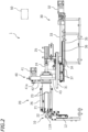
FIG. 2 is a side view of the untwisting device. -
FIG. 3(a) is a plan view of a multi-core cable, andFIG. 3(b) is a plan view of the multi-core cable showing the inside of a tip portion. -
FIG. 4 is a side view of a gripping clamp. -
FIG. 5 is a cross-sectional view of the gripping clamp. -
FIG. 6 is a front view of the gripping clamp. -
FIG. 7 is a block diagram of a control device and actuators. -
FIG. 8 is a functional block diagram of the control device. -
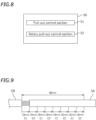
FIG. 9 is a diagram showing the relationship between the sheath tip portion pull-out sections and the control performed in those sections in one embodiment. -
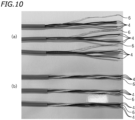
FIG. 10(a) is a photograph showing a sample of a multi-core cable of which the sheath tip portion has been pulled out by the method of the embodiment, andFIG. 10(b) is a photograph showing a sample of a multi-core cable of which the sheath tip portion has been pulled out by a conventional method. -
FIG. 11 is a diagram showing the relationship between the sheath tip portion pull-out sections and the control performed in those sections in another embodiment. -
FIG. 12 is a diagram showing the relationship between the sheath tip portion pull-out sections and the control performed in those sections in another embodiment. - A multi-core cable untwisting device (hereinafter referred to simply as an "untwisting device") according to one embodiment of the present invention will be described with reference to the drawings.
FIG. 1 is a perspective view of anuntwisting device 1, andFIG. 2 is a side view of theuntwisting device 1.FIG. 3(a) is a plan view of amulti-core cable 3, andFIG. 3(b) is a plan view showing the inside of a tip portion of themulti-core cable 3. - As shown in
FIG. 3(a) and FIG. 3(b) , themulti-core cable 3 includes a plurality of coveredelectric wires 4, one uncoveredelectric wire 6, and asheath 5 covering thesewires electric wire 6 includes a plurality of strands made of a conductor such as a metal. Theelectric wires 4 each include a plurality of strands made of a conductive material such as a metal, and a cover covering those strands that is made of an insulating material such as a synthetic resin. Hereafter, the coveredelectric wires 4 and the uncoveredelectric wire 6 are referred to as core wires and a drain wire, respectively. Here, themulti-core cable 3 includes fourcore wires 4. Note however that there is no particular limitation on the number ofcore wires 4. Also, there is no particular limitation on the number ofdrain wires 6. While there is no particular limitation on the material of thesheath 5, it may be chloroprene rubber, polyvinyl chloride, polyethylene, etc., for example. - As shown in
FIG. 3(a) , thesheath 5 of themulti-core cable 3 to be processed by the untwistingdevice 1 has a cut (also called a slit) 5C in advance. By thecut 5C, thesheath 5 is severed into a tip portion (hereinafter referred to as the sheath tip portion) 5A and anon-tip portion 5B. As shown inFIG. 3(b) , thecore wires 4 and thedrain wire 6 are twisted in thesheath 5. That is, thecore wires 4 and thedrain wire 6 in thesheath 5 extend in spiral and are kinked. The untwistingdevice 1 pulls out thesheath tip portion 5A while correcting the kinks in thecore wires 4 and thedrain wire 6 to be exposed. - As shown in
FIG. 1 , the untwistingdevice 1 includes aretention device 10 for retaining thenon-tip portion 5B of thesheath 5 of themulti-core cable 3, a grippingdevice 20 for gripping thesheath tip portion 5A, a pull-outdevice 30 for pulling out thesheath tip portion 5A, and arotating device 40 for rotating thesheath tip portion 5A. As shown inFIG. 2 , the untwistingdevice 1 includes acontrol device 50 for controlling theretention device 10, the grippingdevice 20, the pull-outdevice 30 and therotating device 40. In the following description, for the purpose of discussion, thetip portion 5A side of the sheath 5 (the right side ofFIG. 2 ) will be referred to as the front side and thenon-tip portion 5B side (the left side ofFIG. 2 ) as the rear side. Thesheath tip portion 5A is pulled out forward. - As shown in
FIG. 1 , theretention device 10 includes aretention clamp 11 having a pair of left andright clamp jaws actuator 12 that drives theclamp jaws actuator 12, theactuator 12 is herein an air cylinder. When theclamp jaws retention clamp 11 is closed. Then, thenon-tip portion 5B of thesheath 5 is held by being clamped between theclamp jaws clamp jaws retention clamp 11 is opened. Then, the retention of thenon-tip portion 5B of thesheath 5 is released. - The
gripping device 20 includes agripping clamp 26 and anactuator 25 that opens and closes thegripping clamp 26. -
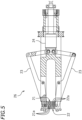
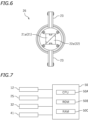
FIG. 4 is a side view of thegripping clamp 26, andFIG. 5 is a cross-sectional view of thegripping clamp 26.FIG. 6 is a front view of thegripping clamp 26. Thegripping clamp 26 includes afirst clamp jaw 21 and asecond clamp jaw 22. Thefirst clamp jaw 21 and thesecond clamp jaw 22 oppose each other so that thesheath tip portion 5A can be gripped. Here, thefirst clamp jaw 21 includes a plurality oftriangular plate members 21a arranged in the front-rear direction (seeFIG. 5 andFIG. 6 ). Thesecond clamp jaw 22 includes a plurality oftriangular plate members 22a arranged in the front-rear direction. Theplate member 21a and theplate member 22a are arranged alternating with each other in the front-rear direction. Note that the configuration of thefirst clamp jaw 21 and thesecond clamp jaw 22 described herein is merely an example. There is no particular limitation on the configuration of thefirst clamp jaw 21 and thesecond clamp jaw 22 as long as thesheath tip portion 5A can be gripped. - When the
first clamp jaw 21 and thesecond clamp jaw 22 are moved toward each other, thesheath tip portion 5A is clamped by thefirst clamp jaw 21 and thesecond clamp jaw 22. As a result, thesheath tip portion 5A is gripped by thefirst clamp jaw 21 and thesecond clamp jaw 22. When thefirst clamp jaw 21 and thesecond clamp jaw 22 are moved away from each other, the grip of thesheath tip portion 5A is released. - As shown in
FIG. 5 , thegripping clamp 26 includes alink mechanism 23 that is linked to thefirst clamp jaw 21 and thesecond clamp jaw 22, and apiston rod 24 linked to thelink mechanism 23. As shown inFIG. 2 , thepiston rod 24 is linked to theactuator 25. While there is no particular limitation on theactuator 25, it is herein an air cylinder. Thepiston rod 24 is rotatably linked to theactuator 25. As shown inFIG. 2 , when theactuator 25 moves thepiston rod 24 forward (rightward inFIG. 2 ), thefirst clamp jaw 21 and thesecond clamp jaw 22 move away from each other. That is, when thepiston rod 24 is extended forward, thegripping clamp 26 is opened, thereby releasing the grip of thegripping clamp 26. On the other hand, as shown inFIG. 4 andFIG. 5 , when theactuator 25 moves thepiston rod 24 rearward, thefirst clamp jaw 21 and thesecond clamp jaw 22 move toward each other. That is, when thepiston rod 24 contracts, thegripping clamp 26 is closed, and thegripping clamp 26 grips thesheath tip portion 5A. Note that the solid line inFIG. 4 represents the state in which thegripping clamp 26 is closed, and the two-dot-chain line represents the state in which thegripping clamp 26 is open. Thus, thegripping clamp 26 is opened and closed by theactuator 25. Note that thepiston rod 24 is not shown inFIG. 1 . - As shown in
FIG. 1 , the rotatingdevice 40 includes asupport plate 43 that rotatably supports thegripping clamp 26 and amotor 41 that gives a torque to thegripping clamp 26. Themotor 41 is supported by thesupport plate 43. Arotary shaft 41a of themotor 41 and thegripping clamp 26 are linked together by abelt 42. Thebelt 42 is a transmission member that transmits the power of themotor 41 to thegripping clamp 26. Note however that the transmission member is not limited to thebelt 42, but may be a transmission member of any other form such as a gear, a chain, or the like. While themotor 41 is an example of an actuator that gives a torque to thegripping clamp 26, the actuator that provides a torque to thegripping clamp 26 is not limited to themotor 41. In the present embodiment, the rotatingdevice 40 is configured to rotate thesheath tip portion 5A by rotating thegripping clamp 26. - The pull-out
device 30 is configured to pull out thesheath tip portion 5A by moving thegripping clamp 26 away from theretention clamp 11 along the longitudinal direction of themulti-core cable 3. The pull-outdevice 30 includes amovable base 31 that supports thegripping device 20 and therotating device 40, amotor 32 that moves themovable base 31 forward and rearward, and a fixedbase 35 that supports themovable base 31 and themotor 32. Arail 36 that extends in the front-back direction is provided on the fixedbase 35. Aslider 37 that slidably engages with therail 36 is fixed to the lower right portion of themovable base 31. Aball screw 33 is connected to themotor 32. As shown inFIG. 2 , aslider 34 that engages with theball screw 33 is fixed to the lower left portion of themovable base 31. Theslider 34 has a hole (not shown) into which theball screw 33 is inserted. The inner circumference of this hole has a spiral groove formed thereon that engages with theball screw 33. When themotor 32 rotates in one direction, theball screw 33 rotates in the same direction and theslider 34 moves forward. As a result, thegripping clamp 26 moves forward. When themotor 32 rotates in the opposite direction, theball screw 33 also rotates in the opposite direction and theslider 34 moves rearward. As a result, thegripping clamp 26 moves rearward. Thus, as themotor 32 rotates in one direction or in the opposite direction, thegripping clamp 26 moves forward or rearward. - The
control device 50 controls theretention device 10, the grippingdevice 20, the pull-outdevice 30 and therotating device 40. As shown inFIG. 7 , thecontrol device 50 is a computer including aCPU 50A, aROM 50B, a RAM 50C, etc. Thecontrol device 50 is communicatively connected to theactuator 12 of theretention device 10, theactuator 25 of thegripping device 20, themotor 32 of the pull-outdevice 30, and themotor 41 of therotating device 40. Thecontrol device 50 may be a dedicated computer for theuntwisting device 1 or a general-purpose computer such as a personal computer. -
FIG. 8 is a functional block diagram of thecontrol device 50. Thecontrol device 50 functions as a pull-outcontrol section 51 and a rotary pull-outcontrol section 52 as follows by executing a computer program stored in theROM 50B or an external storage device, etc. - The pull-out
control section 51 performs a control (hereinafter referred to as "first control") of pulling out thesheath tip portion 5A without rotating thesheath tip portion 5A. Specifically, the pull-outcontrol section 51 drives themotor 32 of the pull-outdevice 30 while stopping themotor 41 of therotation device 40. As a result, thegripping clamp 26, which grips thesheath tip portion 5A, moves forward without rotating. - The rotary pull-out
control section 52 performs a control of pulling out thesheath tip portion 5A while rotating it (hereinafter referred to as "second control"). Specifically, the rotary pull-outcontrol section 52 drives themotor 32 of the pull-outdevice 30 while driving themotor 41 of therotating device 40. Then, thegripping clamp 26, which grips thesheath tip portion 5A, moves forward while rotating. The second control is performed following the first control. In the present embodiment, the first control and the second control are repeated a plurality of times from the start until the end of the pulling-out of thesheath tip portion 5A. Note that the direction in which thecore wires 4 and thedrain wire 6 in thesheath 5 are twisted (hereinafter referred to as the twist direction) is known in advance. In the second control, thesheath tip portion 5A is rotated in the opposite direction to the twist direction of thecore wires 4 and thedrain wire 6. - The untwisting
device 1 is configured as described above. Next, the method for pulling out thesheath tip portion 5A using theuntwisting device 1 will be described. In the following description, the method of pulling out thesheath tip portion 5A at a constant speed while rotating thesheath tip portion 5A at a constant rotation angle from the start until the end of the pulling-out of thesheath tip portion 5A will be called the "conventional method". The pull-out method of the present embodiment will be explained in contrast to the conventional method. - Let L [mm] be the length of the
sheath tip portion 5A to be pulled out (i.e., the strip length), and α [degrees] be the total amount of rotation of thesheath tip portion 5A from the start until the end of the pulling-out. In the conventional method, thesheath tip portion 5A moves forward at a constant speed while rotating at a constant rotation angle from the start until the end of the pulling-out, so the amount of rotation per unit travel distance of thesheath tip portion 5A is α/L [degrees/mm]. For example, where L = 80 [mm] and α = 960 [degrees], thesheath tip portion 5A is pulled out while rotating under α/L = 12 [degrees/mm]. - On the other hand, in the present embodiment, as shown in
FIG. 9 , the period from the start until the end of the pulling-out of thesheath tip portion 5A is divided into eight sections, and the first control and the second control are repeated four times. The symbols C1 and C2 in the figures represent sections where the first control and the second control are performed, respectively. In the first control, thesheath tip portion 5A is pulled out 10 mm at a constant speed without rotation. In the second control, thesheath tip portion 5A is pulled out at a constant speed while rotating thesheath tip portion 5A at a constant speed as with the conventional method. However, in the present embodiment, the total amount of rotation α = 960 [degrees] is made by performing the second control a total of four times, so the amount of rotation per iteration of the second control is 960/4 = 240 [degrees]. The amount of rotation α/L per unit travel distance in the second control is 240/10 = 24 [degrees/mm], which is twice that of the conventional method. -
FIG. 10(a) represents three sample multi-core cables where thesheath tip portion 5A is pulled out by the method according to the present embodiment.FIG. 10(b) represents three sample multi-core cables where thesheath tip portion 5A is pulled out by the conventional method. As can be seen from the comparison betweenFIG. 10(a) and FIG. 10(b) , according to the present embodiment, the kinks in thecore wires 4 and thedrain wire 6 are corrected more desirably than with conventional techniques. - With the
multi-core cable 3, a frictional force is generated between thesheath tip portion 5A and thecore wires 4 and between thesheath tip portion 5A and thedrain wire 6. As thesheath tip portion 5A is rotated, this frictional force transmits a torque on thecore wires 4 and thedrain wire 6, thereby correcting kinks. However, since thesheath tip portion 5A is pulled forward, thecore wires 4 and thedrain wire 6 are also pulled forward by the frictional force. Here, since thecore wires 4 and thedrain wire 6 are twisted, they come into close contact with each other when pulled. If thecore wires 4 and thedrain wire 6 are in close contact with each other, it is assumed that the kinks in thecore wires 4 and thedrain wire 6 cannot be corrected sufficiently unless thesheath tip portion 5A is rotated relatively significantly. In the conventional method, it is assumed that the kinks in thecore wires 4 and thedrain wire 6 cannot be corrected sufficiently because the amount of rotation per unit travel distance of thesheath tip portion 5A is relatively small. - In contrast, in the present embodiment, the first control and the second control are performed, and the amount of rotation per unit travel distance of the
sheath tip portion 5A is relatively large in the second control. The torque per unit travel distance in the second control is twice that of the conventional method. Therefore, it is assumed that the kinks in thecore wires 4 and thedrain wire 6 were corrected sufficiently. Note that while it is possible to rotate thesheath tip portion 5A without pulling out thesheath tip portion 5A, thecore wires 4 and thedrain wire 6 may bulge outward in the radial direction from the center of rotation, resulting in buckling, depending on the operating conditions of the device. However, in the second control, thesheath tip portion 5A is rotated while being pulled out. Therefore, it is possible to prevent the buckling of thecore wires 4 and thedrain wire 6. - Now, one may consider increasing the amount of rotation per unit travel distance in the conventional method. For example, one may consider setting it to α/L = 24 [degrees/mm] in the conventional method. In that case, however, the total amount of rotation of the
sheath tip portion 5A is 24 [degrees/mm] × 80 [mm] = 1920 degrees. The total amount of rotation is twice as large. However, if the total amount of rotation is too large, thecore wires 4 and thedrain wire 6 may be untwisted excessively in the opposite direction to the twist direction, thereby lowering the quality of thecore wires 4 and thedrain wire 6. There is a risk of creating new kinks in thecore wires 4 and thedrain wire 6 in the opposite direction. On the other hand, according to the present embodiment, thesheath tip portion 5A is not rotated in the first control. Therefore, even if the amount of rotation per unit travel distance in the second control is relatively large, the total amount of rotation of thesheath tip portion 5A is not too large. - According to the present embodiment, the
sheath tip portion 5A can be pulled out desirably and the kinks in thecore wires 4 and thedrain wire 6 can be corrected desirably without detracting from the quality of thecore wires 4 and thedrain wire 6. According to the present embodiment, as with the conventional method, it is possible to simultaneously pull out thesheath tip portion 5A while correcting thecore wires 4 and thedrain wire 6, and it is therefore possible to shorten the cycle time for processing themulti-core cable 3. In addition, according to the present embodiment, the kinks in thecore wires 4 and thedrain wire 6 can be corrected more desirably than with conventional techniques, and it is therefore possible to desirably perform subsequent processes on thecore wires 4 and thedrain wire 6. It becomes easier to automate subsequent processes for thecore wires 4 and thedrain wire 6. - Now, if the
sheath tip portion 5A is rotated when thesheath tip portion 5A is in the vicinity of the tip of thecore wires 4 and thedrain wire 6, the near-tip portions of thecore wires 4 and thedrain wire 6 can be untwisted but the base portions cannot be untwisted. Such a tendency is pronounced particularly when the strip length is long. In the present embodiment, however, the first control and the second control are repeated a plurality of times. Therefore, thecore wires 4 and thedrain wire 6 can be untwisted frequently from the start until the end of the pulling-out of thesheath tip portion 5A. In the second control, the kinks can be corrected intensively for the portion where thesheath tip portion 5A has been pulled out in the first control. For example, during the first iteration of the second control, the base portions of thecore wires 4 and thedrain wire 6 can be untwisted sufficiently. During the fourth iteration of the second control, the tip portions of thecore wires 4 and thedrain wire 6 can be untwisted sufficiently. Therefore, even when the strip length is long, the kinks in thecore wires 4 and thedrain wire 6 can be corrected desirably. - In the present embodiment, the
sheath tip portion 5A is pulled at the same speed in the first control and the second control. The pull-out speed of thesheath tip portion 5A in the first control is equal to the pull-out speed of thesheath tip portion 5A in the second control. That is, the moving speed of thegripping clamp 26 in the first control is equal to the moving speed of thegripping clamp 26 in the second control. Therefore, there is no change in the moving speed of thesheath tip portion 5A when transitioning from the first control to the second control and when transitioning from the second control to the first control. Thus, thesheath tip portion 5A can be pulled out stably. - In the present embodiment, the pull-out length is 10 mm both in the first control and in the second control. The pull-out length in the first control is equal to the pull-out length in the second control. Thus, it is possible to desirably pull out the
sheath tip portion 5A, and it is possible to more desirably correct the kinks in thecore wires 4 and thedrain wire 6. - In the present embodiment, the pull-out length is 10 mm in any of the first to fourth iterations of the first control. The pull-out length is 10 mm in any of the first to fourth iterations of the second control. The pull-out length of the first control is equal between different iterations. The pull-out length of the second control is equal between different iterations. This simplifies the first control and the second control. It is also possible to evenly untwist the
core wires 4 and thedrain wire 6. - With the
untwisting device 1 according to the present embodiment, the rotatingdevice 40 is configured to rotate thegripping clamp 26. Thesheath tip portion 5A is rotated by rotating thegripping clamp 26, which grips thesheath tip portion 5A. Therefore, it is possible to stably rotate thesheath tip portion 5A. Therefore, it is possible to stably perform the first control and the second control. With the configuration in which the sheath tip portion is rotated by moving the upper member and the lower member, which clamp the sheath, in opposite directions (see Utility Model Application Publication No.3-120622 rotating device 40 according to the present embodiment, thegripping clamp 26 does not become larger even if the amount of rotation of thesheath tip portion 5A is large. Thus, regardless of the amount of rotation of thesheath tip portion 5A, thegripping clamp 26 can be made smaller. - Note that, in the
untwisting device 1, there is no particular limitation on the travel distance of thegripping clamp 26 when pulling out thesheath tip portion 5A. In other words, there is no particular limitation on the length of thesheath tip portion 5A to be pulled out (the strip length). Note however that, typically, the longer the strip length, the more difficult it is to correct the kinks in thecore wires 4 and thedrain wire 6. Therefore, the longer the strip length of themulti-core cable 3, the more pronounced the effect of theuntwisting device 1 according to the present embodiment, i.e., the effect of desirably correcting the kinks in thecore wires 4 and thedrain wire 6. For example, when the strip length is 60 mm or more, the untwistingdevice 1 according to the present embodiment is particularly effective. Thecontrol device 50 may be configured to pull out thesheath tip portion 5A by 60 mm or more from the start until the end of the pulling-out of thesheath tip portion 5A. - While one embodiment of the present invention has been described above, the embodiment is merely an example and various other embodiments are possible. Next, examples of other embodiments will be described.
- In the embodiment described above, the pull-out length in the first control and the pull-out length in the second control are equal, both being 10 mm. However, the pull-out length in the first control and the pull-out length in the second control may be different. For example, as shown in
FIG. 11 , when the strip length is 90 mm, the pull-out length in the first control may be 20 mm and the pull-out length in the second control may be 10 mm. In this case, the pull-out length in the second control (= 10 mm) is 1/3 of the total pull-out length in the first control and the second control (= 30 mm). The amount of rotation in the second control can be set as desired. For example, the amount of rotation per unit travel distance α/L in the second control may be three times the amount of rotation per unit travel distance α/L according to the conventional method. Note that the pull-out length in the first control may be longer or shorter than the pull-out length in the second control. - In the embodiment described above (see
FIG. 9 ), the pull-out length is equal in each iteration of the first control and the pull-out length is equal in each iteration of the second control. For example, the pull-out length of the first iteration of the first control is 10 mm, and the pull-out length of the second iteration of the first control is 10 mm. However, the pull-out length may differ between a plurality of iterations of the first control. The pull-out length may also differ between a plurality of iterations of the second control. For example, as shown inFIG. 12 , the pull-out length of the first iteration of the first control may be 50 mm, and the pull-out length of the second iteration of the first control may be 20 mm. - Where the first control and the second control are performed for a plurality of iterations, the amount of rotation per unit travel distance α/L may be constant for different iterations. Thus, it is possible to evenly correct the kinks in the
core wires 4 and thedrain wire 6. αn/La = αn+1/Ln+1 may hold, where n is a predetermined natural number, Ln is the total pull-out length for the nth iteration of the first control and the second control, αn is the amount of rotation of the nth iteration of the second control, Ln+1 is the total pull-out length for the n+1th iteration of the first control and the second control, and αn+1 is the amount of rotation of the n+1th iteration of the second control. For example, in the example shown inFIG. 12 , since L1 = 60 mm and L2 = 30 mm, α1/60 = α2/30 may be set. Then, α2 = 0.5×α1. - In the example described above, L2 is shorter than L1, and α2 is smaller than α1. Thus, where the first control and the second control are performed for a plurality of iterations, the amount of rotation may be set to be smaller as the total pull-out length for each iteration is shorter. Where the total pull-out length of the nth iteration of the first control and the second control is shorter than the total pull-out length of the mth iteration (where m is a predetermined natural number other than n) of the first control and the second control, the amount of rotation of the nth iteration of the second control may be smaller than the amount of rotation of the mth iteration of the second control. Thus, the kinks in the
core wires 4 and thedrain wire 6 can be corrected relatively evenly. - The pull-out speed may be equal or may differ between the first control and the second control. The pull-out speed may differ between iterations of the first control. The pull-out speed may difference between iterations of the second control. For example, the pull-out speed may become higher or lower for later iterations.
- The first control and the second control may be performed only for one iteration. For example, for the
multi-core cable 3 with a short strip length, the kinks in thecore wires 4 and thedrain wire 6 can be corrected desirably even if the first control and the second control are performed only for one iteration. - While the first control is performed immediately after the start of the pulling-out of the
sheath tip portion 5A in the embodiment described above, the second control may be performed immediately after the start of the pulling-out. - While the
sheath tip portion 5A is not rotated in the first control in the embodiment described above, thesheath tip portion 5A may be pulled out while being rotated in the first control. Where the total amount of rotation of thesheath tip portion 5A is constant, the amount of rotation per unit travel distance α/L in the second control can be made larger than with conventional techniques by making the amount of rotation per unit travel distance α/L in the first control smaller than with conventional techniques. For example, in the first control, thesheath tip portion 5A is pulled out while being rotated at the first rotation speed, and in the second control, thesheath tip portion 5A is pulled out while being rotated at the second rotation speed greater than the first rotation speed. Even with such a control, α/L in the second control can be made larger than with the conventional method. Therefore, the kinks in thecore wires 4 and thedrain wire 6 can be corrected more desirably than with the conventional method. - Only the first control and the second control may be performed from the start until the end of the pulling-out of the
sheath tip portion 5A, or other controls may be performed in addition to the first control and the second control. For example, immediately after the start of the pulling-out of thesheath tip portion 5A, a control may be performed to pull out thesheath tip portion 5A while rotating thesheath tip portion 5A in the same direction as the twist direction of thecore wires 4 and thedrain wire 6, and the first control and the second control may be performed thereafter. Note that while thesheath tip portion 5A is pulled out while being rotated in the second control, the rotation direction in this operation is the opposite direction to the twist direction of thecore wires 4 and thedrain wire 6. - There is no particular limitation on the method for rotating the
sheath tip portion 5A. There is no particular limitation on the configuration for rotating thesheath tip portion 5A. For example, thegripping clamp 26 may include a pair of upper and lower clamp members, and these clamp members may be configured to move in opposite directions to each other in the left-right direction while clamping thesheath tip portion 5A. In this case, thesheath tip portion 5A is rotated by being rolled by the pair of upper and lower clamp members. - In the embodiment described above, the
sheath tip portion 5A is rotated while thenon-tip portion 5B of thesheath 5 is held stationary. However, it is sufficient to be able to rotate thesheath tip portion 5A relative to thenon-tip portion 5B, and there is no particular limitation on the configuration and operation of the rotating device. Thenon-tip portion 5B of thesheath 5 may be rotated while not rotating thesheath tip portion 5A. Both thesheath tip portion 5A and thenon-tip portion 5B may be rotated in opposite directions of each other. - There is no particular limitation on the configuration of the
gripping clamp 26. Thegripping clamp 26 may include any configuration capable of gripping thesheath tip portion 5A. For example, thegripping clamp 26 may be provided with a pair of plate-like members that grip thesheath tip portion 5A instead of thefirst clamp jaw 21 and thesecond clamp jaw 22. - In the present embodiment, the
multi-core cable 3 includes fourcore wires 4 and onedrain wire 6. However, there is no particular limitation on the number ofcore wires 4 and the number ofdrain wires 6. Thedrain wire 6 may not be necessary. Themulti-core cable 3 may include a plurality of covered electric wires and include no uncovered electric wire. Themulti-core cable 3 may include a plurality of uncovered electric wires and include no covered electric wire. - In the embodiment described above, the pull-out
device 30 is configured to pull out thesheath tip portion 5A by moving thegripping clamp 26. However, the pull-outdevice 30 may be configured to pull out thesheath tip portion 5A by moving theretention clamp 11 away from thegripping clamp 26. The pull-outdevice 30 may also be configured to pull out thesheath tip portion 5A by moving both thegripping clamp 26 and theretention clamp 11 so that thegripping clamp 26 moves away from theretention clamp 11. -
- 1
- Multi-core cable untwisting device
- 3
- Multi-core cable
- 4
- Covered electric wire (core wire)
- 5
- Sheath
- 5A
- Tip portion of sheath
- 5B
- Non-tip portion of sheath
- 6
- Uncovered electric wire (drain wire)
- 10
- Retention device
- 11
- Retention clamp (retention member)
- 12
- Actuator
- 20
- Gripping device
- 25
- Actuator
- 26
- Gripping clamp (gripping member)
- 30
- Pull-out device
- 32
- Motor
- 40
- Rotating device
- 41
- Motor (actuator)
- 50
- Control device
Claims (9)
- A multi-core cable untwisting device (1) for pulling out a tip portion (5A) of a sheath (5) of a multi-core cable (3), which includes a plurality of electric wires (4) and the sheath (5) that covers the electric wires (4), while correcting kinks in the electric wires (4), the multi-core cable untwisting device (1) comprising:a retention member (11) configured to retain a non-tip portion (5B) of the sheath (5) that has a cut between the tip portion (5A) and the non-tip portion (5B);a gripping member (26) configured to grip the tip portion (5A) of the sheath (5);a pull-out device (30) configured to pull out the tip portion (5A) of the sheath (5) by moving at least one of the gripping member (26) and the retention member (11) so that the gripping member (26) moves away from the retention member (11);a rotating device (40) configured to relatively rotate the tip portion (5A) of the sheath (5) that is gripped by the gripping member (26) and the non-tip portion (5B) of the sheath (5); anda control device (50) configured to control the pull-out device (30) and the rotating device (40),characterized in thatthe control device (50) is configured to perform a first control and a second control from start until end of the pulling-out of the tip portion (5A) of the sheath (5), wherein the first control is to control the pull-out device (30) and the rotating device (40) so that the amount of rotation per unit travel distance of the tip portion (5A) of the sheath (5) is smaller than a predetermined amount of rotation, and the second control is to control the pull-out device (30) and the rotating device (40) so that the amount of rotation per unit travel distance of the tip portion (5A) of the sheath (5) is equal to or greater than the predetermined amount of rotation.
- The multi-core cable untwisting device (1) according to claim 1, wherein the control device (50) is configured to pull out the tip portion (5A) of the sheath (5) without rotating the tip portion (5A) of the sheath (5) in the first control, and to pull out the tip portion (5A) of the sheath (5) while rotating the tip portion (5A) of the sheath (5) in the second control.
- The multi-core cable untwisting device (1) according to claim 1 or 2, wherein the control device (50) is configured to perform the second control after the first control.
- The multi-core cable untwisting device (1) according to any one of claims 1 to 3, wherein the control device (50) is configured to repeat the first control and the second control for two iterations or more from start until end of the pulling-out of the tip portion (5A) of the sheath (5).
- The multi-core cable untwisting device (1) according to claim 4, wherein a pull-out length of the first control is equal between different iterations and/or a pull-out length of the second control is equal between different iterations.
- The multi-core cable untwisting device (1) according to claim 4 or 5, wherein:a total pull-out length of the tip portion (5A) of the sheath (5) in an nth iteration (where n is a predetermined natural number) of the first control and the second control is shorter than a total pull-out length of the tip portion (5A) of the sheath (5) in an mth iteration (where m is a predetermined natural number other than n) of the first control and the second control; andthe amount of rotation of the tip portion (5A) of the sheath (5) in the nth iteration of the second control is smaller than the amount of rotation of the tip portion (5A) of the sheath (5) in the mth iteration of the second control.
- The multi-core cable untwisting device (1) according to claim 4 or 5, wherein αn/La = αn+1/Ln+1 holds, where Ln is a total pull-out length of the tip portion (5A) of the sheath (5) in an nth iteration (where n is a predetermined natural number) of the first control and the second control, αn is the amount of rotation of the tip portion (5A) of the sheath (5) in the nth iteration of the second control, Ln+1 is a total pull-out length of the tip portion (5A) of the sheath (5) in an n+1th iteration of the first control and the second control, and αn+1 is the amount of rotation of the tip portion (5A) of the sheath (5) in the n+1th iteration of the second control.
- The multi-core cable untwisting device (1) according to any one of claims 1 to 7, wherein the rotating device (40) includes an actuator (41) configured to rotate the gripping member (26).
- The multi-core cable untwisting device (1) according to any one of claims 1 to 8, wherein the control device (50) is configured to pull out the tip portion (5A) of the sheath (5) by 60 mm or more from the start until the end of the pulling-out of the tip portion (5A) of the sheath (5).
Applications Claiming Priority (2)
| Application Number | Priority Date | Filing Date | Title |
|---|---|---|---|
| JP2020179422 | 2020-10-27 | ||
| PCT/JP2021/037935 WO2022091788A1 (en) | 2020-10-27 | 2021-10-13 | Multicore cable untwisting device |
Publications (3)
| Publication Number | Publication Date |
|---|---|
| EP4239819A1 EP4239819A1 (en) | 2023-09-06 |
| EP4239819A4 EP4239819A4 (en) | 2024-04-10 |
| EP4239819B1 true EP4239819B1 (en) | 2025-02-26 |
Family
ID=81383808
Family Applications (1)
| Application Number | Title | Priority Date | Filing Date |
|---|---|---|---|
| EP21885907.2A Active EP4239819B1 (en) | 2020-10-27 | 2021-10-13 | Multicore cable untwisting device |
Country Status (5)
| Country | Link |
|---|---|
| US (1) | US12381377B2 (en) |
| EP (1) | EP4239819B1 (en) |
| JP (1) | JP7495519B2 (en) |
| CN (1) | CN116325398B (en) |
| WO (1) | WO2022091788A1 (en) |
Families Citing this family (4)
| Publication number | Priority date | Publication date | Assignee | Title |
|---|---|---|---|---|
| US20240079863A1 (en) * | 2020-12-24 | 2024-03-07 | Shinmaywa Industries, Ltd. | Drain wire correcting device and drain wire correcting method |
| EP4654404A4 (en) | 2023-01-18 | 2026-04-08 | Shinmaywa Ind Ltd | MULTI-CORE CABLE PROCESSING APPARATUS |
| WO2025141643A1 (en) * | 2023-12-25 | 2025-07-03 | 新明和工業株式会社 | Multicore cable untwisting device |
| CN120784698A (en) * | 2024-04-01 | 2025-10-14 | 泰科电子(上海)有限公司 | Twisted pair cable processing system, twisted pair cable cutting method and untwisting method |
Family Cites Families (15)
| Publication number | Priority date | Publication date | Assignee | Title |
|---|---|---|---|---|
| AU473521B2 (en) * | 1972-05-31 | 1976-06-24 | Amp Incorporated | A method of and apparatus for stripping a twisted pair of insulated wires |
| US3853156A (en) | 1972-05-31 | 1974-12-10 | Amp Inc | Insulation stripper and wire separator for twisted wire pairs |
| JPH0719381B2 (en) | 1989-10-04 | 1995-03-06 | 松下電器産業株式会社 | Focus pull-in method |
| JPH03120622U (en) * | 1990-03-26 | 1991-12-11 | ||
| JPH0685609B2 (en) * | 1991-12-13 | 1994-10-26 | 日本オートマチックマシン株式会社 | Pair electric wire cartridge insertion device |
| JPH0613321U (en) * | 1991-12-16 | 1994-02-18 | 日本オートマチックマシン株式会社 | Pair electric wire sorting device |
| JP2962099B2 (en) | 1993-05-14 | 1999-10-12 | 住友電装株式会社 | Rotary wire hammer remover |
| JPH08336219A (en) | 1995-06-07 | 1996-12-17 | Sumitomo Wiring Syst Ltd | Termination of shield wire |
| JP3120622U (en) | 2006-01-31 | 2006-04-13 | 尾崎商事株式会社 | Student cutter shirts |
| CN102656304B (en) | 2009-12-17 | 2014-11-26 | 奥菲奇内·马卡费里股份公司 | Plastic open mesh net manufacturing device and machine |
| CN103106982B (en) | 2013-01-29 | 2016-12-07 | 东莞市精铁机械有限公司 | Active back-twist constant-force pay-off machine and preparation method thereof |
| PT2801984T (en) * | 2013-05-08 | 2019-01-23 | Schleuniger Holding Ag | Gripper, twisting head and twisting head device |
| EP3163696B1 (en) * | 2015-10-28 | 2019-06-12 | Schleuniger Holding AG | Stripping head and method of operating the same |
| US20170231640A1 (en) * | 2016-02-11 | 2017-08-17 | Cook Medical Technologies Llc | Flow diverter with reinforced portion |
| CN210778042U (en) * | 2019-11-05 | 2020-06-16 | 苏州朝隆机械有限公司 | A vertical back-twisting device |
-
2021
- 2021-10-13 EP EP21885907.2A patent/EP4239819B1/en active Active
- 2021-10-13 US US18/027,642 patent/US12381377B2/en active Active
- 2021-10-13 WO PCT/JP2021/037935 patent/WO2022091788A1/en not_active Ceased
- 2021-10-13 CN CN202180066451.3A patent/CN116325398B/en active Active
- 2021-10-13 JP JP2022558990A patent/JP7495519B2/en active Active
Also Published As
| Publication number | Publication date |
|---|---|
| WO2022091788A1 (en) | 2022-05-05 |
| CN116325398A (en) | 2023-06-23 |
| EP4239819A4 (en) | 2024-04-10 |
| US20230387670A1 (en) | 2023-11-30 |
| US12381377B2 (en) | 2025-08-05 |
| JPWO2022091788A1 (en) | 2022-05-05 |
| CN116325398B (en) | 2025-08-19 |
| EP4239819A1 (en) | 2023-09-06 |
| JP7495519B2 (en) | 2024-06-04 |
Similar Documents
| Publication | Publication Date | Title |
|---|---|---|
| US12381377B2 (en) | Multi-core cable untwisting device | |
| CA2881754C (en) | Apparatus and methods for automatically twisting metal wires for connecting structural elements | |
| US9240662B2 (en) | Terminal treatment method and terminal treatment apparatus for coaxial cable | |
| CN110867778B (en) | Cable braid opening mechanism for cable preparation machine | |
| CN110391053B (en) | Apparatus and method for stranding first and second single wires to form a duplex cable | |
| US4019409A (en) | Stripping and defillering method and apparatus | |
| CN103490348A (en) | A fully automatic coaxial wire stripping machine capable of stripping ultra-short wires | |
| US12544825B2 (en) | Method and device for untwisting and smoothing a cable end of a twisted cable | |
| CN113517662A (en) | Apparatus and method for removing sheathing of electrical conductors | |
| EP3692613B1 (en) | Wire preparation device | |
| JP7535599B2 (en) | Drain wire straightening device and drain wire straightening method | |
| JP2016063707A (en) | Tubular outer package mounting device and manufacturing method of wire module with tubular outer package member | |
| JP2003032825A (en) | Wire stripping method and stripping device | |
| WO2025141643A1 (en) | Multicore cable untwisting device | |
| US6038765A (en) | Process and device for connecting a cord made of filaments to a drilled hole or sheath | |
| JP6678048B2 (en) | Wire twisting device | |
| JP7615339B2 (en) | Multi-core cable core alignment device | |
| JP3017271B2 (en) | Stripping device for insulated wire | |
| JP2914976B2 (en) | Wire cutting method in winding machine | |
| US1554916A (en) | Cable-stripping machine | |
| JPS5820204B2 (en) | Wire stripping and twisting equipment | |
| CN212033409U (en) | A sheathed flexible cable stripper | |
| JP2022133924A (en) | Manufacturing method of hollow covering twisted wire | |
| JPH07170626A (en) | Core wire stranding machine for automatic closing end processing apparatus | |
| ITMI20000751A1 (en) | EQUIPMENT AND METHOD FOR THE PROCESSING OF COATED CABLES |
Legal Events
| Date | Code | Title | Description |
|---|---|---|---|
| STAA | Information on the status of an ep patent application or granted ep patent |
Free format text: STATUS: THE INTERNATIONAL PUBLICATION HAS BEEN MADE |
|
| PUAI | Public reference made under article 153(3) epc to a published international application that has entered the european phase |
Free format text: ORIGINAL CODE: 0009012 |
|
| STAA | Information on the status of an ep patent application or granted ep patent |
Free format text: STATUS: REQUEST FOR EXAMINATION WAS MADE |
|
| 17P | Request for examination filed |
Effective date: 20230309 |
|
| AK | Designated contracting states |
Kind code of ref document: A1 Designated state(s): AL AT BE BG CH CY CZ DE DK EE ES FI FR GB GR HR HU IE IS IT LI LT LU LV MC MK MT NL NO PL PT RO RS SE SI SK SM TR |
|
| DAV | Request for validation of the european patent (deleted) | ||
| DAX | Request for extension of the european patent (deleted) | ||
| REG | Reference to a national code |
Ref country code: DE Ref legal event code: R079 Free format text: PREVIOUS MAIN CLASS: H02G0001140000 Ipc: H01R0043280000 Ref document number: 602021026929 Country of ref document: DE |
|
| A4 | Supplementary search report drawn up and despatched |
Effective date: 20240307 |
|
| RIC1 | Information provided on ipc code assigned before grant |
Ipc: H02G 1/12 20060101ALN20240301BHEP Ipc: H01R 43/28 20060101AFI20240301BHEP |
|
| GRAP | Despatch of communication of intention to grant a patent |
Free format text: ORIGINAL CODE: EPIDOSNIGR1 |
|
| STAA | Information on the status of an ep patent application or granted ep patent |
Free format text: STATUS: GRANT OF PATENT IS INTENDED |
|
| GRAJ | Information related to disapproval of communication of intention to grant by the applicant or resumption of examination proceedings by the epo deleted |
Free format text: ORIGINAL CODE: EPIDOSDIGR1 |
|
| STAA | Information on the status of an ep patent application or granted ep patent |
Free format text: STATUS: REQUEST FOR EXAMINATION WAS MADE |
|
| RIC1 | Information provided on ipc code assigned before grant |
Ipc: H02G 1/12 20060101ALN20241017BHEP Ipc: H01R 43/28 20060101AFI20241017BHEP |
|
| GRAP | Despatch of communication of intention to grant a patent |
Free format text: ORIGINAL CODE: EPIDOSNIGR1 |
|
| STAA | Information on the status of an ep patent application or granted ep patent |
Free format text: STATUS: GRANT OF PATENT IS INTENDED |
|
| INTG | Intention to grant announced |
Effective date: 20241029 |
|
| INTC | Intention to grant announced (deleted) | ||
| P01 | Opt-out of the competence of the unified patent court (upc) registered |
Free format text: CASE NUMBER: APP_60858/2024 Effective date: 20241113 |
|
| INTG | Intention to grant announced |
Effective date: 20241122 |
|
| RIC1 | Information provided on ipc code assigned before grant |
Ipc: H02G 1/12 20060101ALN20241115BHEP Ipc: H01R 43/28 20060101AFI20241115BHEP |
|
| GRAS | Grant fee paid |
Free format text: ORIGINAL CODE: EPIDOSNIGR3 |
|
| GRAA | (expected) grant |
Free format text: ORIGINAL CODE: 0009210 |
|
| STAA | Information on the status of an ep patent application or granted ep patent |
Free format text: STATUS: THE PATENT HAS BEEN GRANTED |
|
| AK | Designated contracting states |
Kind code of ref document: B1 Designated state(s): AL AT BE BG CH CY CZ DE DK EE ES FI FR GB GR HR HU IE IS IT LI LT LU LV MC MK MT NL NO PL PT RO RS SE SI SK SM TR |
|
| REG | Reference to a national code |
Ref country code: GB Ref legal event code: FG4D |
|
| REG | Reference to a national code |
Ref country code: CH Ref legal event code: EP |
|
| REG | Reference to a national code |
Ref country code: DE Ref legal event code: R096 Ref document number: 602021026929 Country of ref document: DE |
|
| REG | Reference to a national code |
Ref country code: IE Ref legal event code: FG4D |
|
| REG | Reference to a national code |
Ref country code: NL Ref legal event code: MP Effective date: 20250226 |
|
| PG25 | Lapsed in a contracting state [announced via postgrant information from national office to epo] |
Ref country code: RS Free format text: LAPSE BECAUSE OF FAILURE TO SUBMIT A TRANSLATION OF THE DESCRIPTION OR TO PAY THE FEE WITHIN THE PRESCRIBED TIME-LIMIT Effective date: 20250526 |
|
| PG25 | Lapsed in a contracting state [announced via postgrant information from national office to epo] |
Ref country code: FI Free format text: LAPSE BECAUSE OF FAILURE TO SUBMIT A TRANSLATION OF THE DESCRIPTION OR TO PAY THE FEE WITHIN THE PRESCRIBED TIME-LIMIT Effective date: 20250226 |
|
| PG25 | Lapsed in a contracting state [announced via postgrant information from national office to epo] |
Ref country code: PL Free format text: LAPSE BECAUSE OF FAILURE TO SUBMIT A TRANSLATION OF THE DESCRIPTION OR TO PAY THE FEE WITHIN THE PRESCRIBED TIME-LIMIT Effective date: 20250226 |
|
| PG25 | Lapsed in a contracting state [announced via postgrant information from national office to epo] |
Ref country code: ES Free format text: LAPSE BECAUSE OF FAILURE TO SUBMIT A TRANSLATION OF THE DESCRIPTION OR TO PAY THE FEE WITHIN THE PRESCRIBED TIME-LIMIT Effective date: 20250226 |
|
| REG | Reference to a national code |
Ref country code: LT Ref legal event code: MG9D |
|
| PG25 | Lapsed in a contracting state [announced via postgrant information from national office to epo] |
Ref country code: IS Free format text: LAPSE BECAUSE OF FAILURE TO SUBMIT A TRANSLATION OF THE DESCRIPTION OR TO PAY THE FEE WITHIN THE PRESCRIBED TIME-LIMIT Effective date: 20250626 Ref country code: NO Free format text: LAPSE BECAUSE OF FAILURE TO SUBMIT A TRANSLATION OF THE DESCRIPTION OR TO PAY THE FEE WITHIN THE PRESCRIBED TIME-LIMIT Effective date: 20250526 |
|
| PG25 | Lapsed in a contracting state [announced via postgrant information from national office to epo] |
Ref country code: NL Free format text: LAPSE BECAUSE OF FAILURE TO SUBMIT A TRANSLATION OF THE DESCRIPTION OR TO PAY THE FEE WITHIN THE PRESCRIBED TIME-LIMIT Effective date: 20250226 |
|
| PG25 | Lapsed in a contracting state [announced via postgrant information from national office to epo] |
Ref country code: HR Free format text: LAPSE BECAUSE OF FAILURE TO SUBMIT A TRANSLATION OF THE DESCRIPTION OR TO PAY THE FEE WITHIN THE PRESCRIBED TIME-LIMIT Effective date: 20250226 |
|
| PG25 | Lapsed in a contracting state [announced via postgrant information from national office to epo] |
Ref country code: PT Free format text: LAPSE BECAUSE OF FAILURE TO SUBMIT A TRANSLATION OF THE DESCRIPTION OR TO PAY THE FEE WITHIN THE PRESCRIBED TIME-LIMIT Effective date: 20250626 Ref country code: LV Free format text: LAPSE BECAUSE OF FAILURE TO SUBMIT A TRANSLATION OF THE DESCRIPTION OR TO PAY THE FEE WITHIN THE PRESCRIBED TIME-LIMIT Effective date: 20250226 |
|
| PG25 | Lapsed in a contracting state [announced via postgrant information from national office to epo] |
Ref country code: GR Free format text: LAPSE BECAUSE OF FAILURE TO SUBMIT A TRANSLATION OF THE DESCRIPTION OR TO PAY THE FEE WITHIN THE PRESCRIBED TIME-LIMIT Effective date: 20250527 Ref country code: BG Free format text: LAPSE BECAUSE OF FAILURE TO SUBMIT A TRANSLATION OF THE DESCRIPTION OR TO PAY THE FEE WITHIN THE PRESCRIBED TIME-LIMIT Effective date: 20250226 |
|
| REG | Reference to a national code |
Ref country code: AT Ref legal event code: MK05 Ref document number: 1771634 Country of ref document: AT Kind code of ref document: T Effective date: 20250226 |
|
| PG25 | Lapsed in a contracting state [announced via postgrant information from national office to epo] |
Ref country code: SE Free format text: LAPSE BECAUSE OF FAILURE TO SUBMIT A TRANSLATION OF THE DESCRIPTION OR TO PAY THE FEE WITHIN THE PRESCRIBED TIME-LIMIT Effective date: 20250226 |
|
| PG25 | Lapsed in a contracting state [announced via postgrant information from national office to epo] |
Ref country code: SM Free format text: LAPSE BECAUSE OF FAILURE TO SUBMIT A TRANSLATION OF THE DESCRIPTION OR TO PAY THE FEE WITHIN THE PRESCRIBED TIME-LIMIT Effective date: 20250226 |
|
| PG25 | Lapsed in a contracting state [announced via postgrant information from national office to epo] |
Ref country code: DK Free format text: LAPSE BECAUSE OF FAILURE TO SUBMIT A TRANSLATION OF THE DESCRIPTION OR TO PAY THE FEE WITHIN THE PRESCRIBED TIME-LIMIT Effective date: 20250226 |
|
| PG25 | Lapsed in a contracting state [announced via postgrant information from national office to epo] |
Ref country code: IT Free format text: LAPSE BECAUSE OF FAILURE TO SUBMIT A TRANSLATION OF THE DESCRIPTION OR TO PAY THE FEE WITHIN THE PRESCRIBED TIME-LIMIT Effective date: 20250226 |
|
| PG25 | Lapsed in a contracting state [announced via postgrant information from national office to epo] |
Ref country code: AT Free format text: LAPSE BECAUSE OF FAILURE TO SUBMIT A TRANSLATION OF THE DESCRIPTION OR TO PAY THE FEE WITHIN THE PRESCRIBED TIME-LIMIT Effective date: 20250226 |
|
| PG25 | Lapsed in a contracting state [announced via postgrant information from national office to epo] |
Ref country code: EE Free format text: LAPSE BECAUSE OF FAILURE TO SUBMIT A TRANSLATION OF THE DESCRIPTION OR TO PAY THE FEE WITHIN THE PRESCRIBED TIME-LIMIT Effective date: 20250226 Ref country code: CZ Free format text: LAPSE BECAUSE OF FAILURE TO SUBMIT A TRANSLATION OF THE DESCRIPTION OR TO PAY THE FEE WITHIN THE PRESCRIBED TIME-LIMIT Effective date: 20250226 |
|
| PG25 | Lapsed in a contracting state [announced via postgrant information from national office to epo] |
Ref country code: RO Free format text: LAPSE BECAUSE OF FAILURE TO SUBMIT A TRANSLATION OF THE DESCRIPTION OR TO PAY THE FEE WITHIN THE PRESCRIBED TIME-LIMIT Effective date: 20250226 |
|
| PG25 | Lapsed in a contracting state [announced via postgrant information from national office to epo] |
Ref country code: SK Free format text: LAPSE BECAUSE OF FAILURE TO SUBMIT A TRANSLATION OF THE DESCRIPTION OR TO PAY THE FEE WITHIN THE PRESCRIBED TIME-LIMIT Effective date: 20250226 |
|
| REG | Reference to a national code |
Ref country code: CH Ref legal event code: U11 Free format text: ST27 STATUS EVENT CODE: U-0-0-U10-U11 (AS PROVIDED BY THE NATIONAL OFFICE) Effective date: 20251101 |
|
| REG | Reference to a national code |
Ref country code: DE Ref legal event code: R097 Ref document number: 602021026929 Country of ref document: DE |
|
| PLBE | No opposition filed within time limit |
Free format text: ORIGINAL CODE: 0009261 |
|
| STAA | Information on the status of an ep patent application or granted ep patent |
Free format text: STATUS: NO OPPOSITION FILED WITHIN TIME LIMIT |
|
| PGFP | Annual fee paid to national office [announced via postgrant information from national office to epo] |
Ref country code: DE Payment date: 20251021 Year of fee payment: 5 |
|
| PGFP | Annual fee paid to national office [announced via postgrant information from national office to epo] |
Ref country code: CH Payment date: 20251101 Year of fee payment: 5 |
|
| 26N | No opposition filed |
Effective date: 20251127 |