EP4239792A1 - Basisstationsantenne - Google Patents
Basisstationsantenne Download PDFInfo
- Publication number
- EP4239792A1 EP4239792A1 EP23160023.0A EP23160023A EP4239792A1 EP 4239792 A1 EP4239792 A1 EP 4239792A1 EP 23160023 A EP23160023 A EP 23160023A EP 4239792 A1 EP4239792 A1 EP 4239792A1
- Authority
- EP
- European Patent Office
- Prior art keywords
- radome
- base station
- station antenna
- radio
- radiating element
- Prior art date
- Legal status (The legal status is an assumption and is not a legal conclusion. Google has not performed a legal analysis and makes no representation as to the accuracy of the status listed.)
- Pending
Links
Images




Classifications
-
- H—ELECTRICITY
- H01—ELECTRIC ELEMENTS
- H01Q—ANTENNAS, i.e. RADIO AERIALS
- H01Q1/00—Details of, or arrangements associated with, antennas
- H01Q1/42—Housings not intimately mechanically associated with radiating elements, e.g. radome
-
- H—ELECTRICITY
- H01—ELECTRIC ELEMENTS
- H01Q—ANTENNAS, i.e. RADIO AERIALS
- H01Q1/00—Details of, or arrangements associated with, antennas
- H01Q1/12—Supports; Mounting means
-
- H—ELECTRICITY
- H01—ELECTRIC ELEMENTS
- H01Q—ANTENNAS, i.e. RADIO AERIALS
- H01Q1/00—Details of, or arrangements associated with, antennas
- H01Q1/12—Supports; Mounting means
- H01Q1/22—Supports; Mounting means by structural association with other equipment or articles
- H01Q1/24—Supports; Mounting means by structural association with other equipment or articles with receiving set
- H01Q1/241—Supports; Mounting means by structural association with other equipment or articles with receiving set used in mobile communications, e.g. GSM
- H01Q1/246—Supports; Mounting means by structural association with other equipment or articles with receiving set used in mobile communications, e.g. GSM specially adapted for base stations
-
- H—ELECTRICITY
- H01—ELECTRIC ELEMENTS
- H01Q—ANTENNAS, i.e. RADIO AERIALS
- H01Q1/00—Details of, or arrangements associated with, antennas
- H01Q1/44—Details of, or arrangements associated with, antennas using equipment having another main function to serve additionally as an antenna, e.g. means for giving an antenna an aesthetic aspect
-
- H—ELECTRICITY
- H01—ELECTRIC ELEMENTS
- H01Q—ANTENNAS, i.e. RADIO AERIALS
- H01Q1/00—Details of, or arrangements associated with, antennas
- H01Q1/50—Structural association of antennas with earthing switches, lead-in devices or lightning protectors
-
- H—ELECTRICITY
- H01—ELECTRIC ELEMENTS
- H01Q—ANTENNAS, i.e. RADIO AERIALS
- H01Q19/00—Combinations of primary active antenna elements and units with secondary devices, e.g. with quasi-optical devices, for giving the antenna a desired directional characteristic
- H01Q19/10—Combinations of primary active antenna elements and units with secondary devices, e.g. with quasi-optical devices, for giving the antenna a desired directional characteristic using reflecting surfaces
- H01Q19/104—Combinations of primary active antenna elements and units with secondary devices, e.g. with quasi-optical devices, for giving the antenna a desired directional characteristic using reflecting surfaces using a substantially flat reflector for deflecting the radiated beam, e.g. periscopic antennas
-
- H—ELECTRICITY
- H01—ELECTRIC ELEMENTS
- H01Q—ANTENNAS, i.e. RADIO AERIALS
- H01Q21/00—Antenna arrays or systems
- H01Q21/0006—Particular feeding systems
-
- H—ELECTRICITY
- H01—ELECTRIC ELEMENTS
- H01Q—ANTENNAS, i.e. RADIO AERIALS
- H01Q21/00—Antenna arrays or systems
- H01Q21/06—Arrays of individually energised antenna units similarly polarised and spaced apart
- H01Q21/061—Two dimensional planar arrays
-
- H—ELECTRICITY
- H01—ELECTRIC ELEMENTS
- H01Q—ANTENNAS, i.e. RADIO AERIALS
- H01Q19/00—Combinations of primary active antenna elements and units with secondary devices, e.g. with quasi-optical devices, for giving the antenna a desired directional characteristic
- H01Q19/10—Combinations of primary active antenna elements and units with secondary devices, e.g. with quasi-optical devices, for giving the antenna a desired directional characteristic using reflecting surfaces
Definitions
- the present disclosure generally relates to the field of radio antenna, and more specifically, the present disclosure relates to a base station antenna.
- Base station antennas usually operate in open areas, and are directly subject to the natural forces of rainstorm, snow, dust, and solar radiation, etc., which reduces antenna accuracy of base station antenna systems, shortens their lifespans and causes their work reliability to be poor. Therefore, there is a need to mount a radome in the base station antenna to protect the base station antenna system from external environmental impact. Therefore, how to ensure the stability of the radome in a reliable manner and to prevent the antenna system from being damaged by the toppling of the radome is a technical problem that urgently needs to be solved by those of ordinary skill in the art.
- the objective of the present disclosure is to provide a base station antenna capable of overcoming at least one drawback in the prior art.
- a base station antenna comprises: a radio; a feed board and a radiating element array mounted on the feed board, where the radiating element array comprises a plurality of radiating elements, and each radiating element extends forward from the feed board; a radome arranged in front of the radiating element array; and a plurality of radome supporting members mounted on the radio and extending forward from the radio to the radome for supporting the radome.
- a base station antenna comprises: a feed board; a radiating element array mounted on the feed board, where the radiating element array comprises a plurality of radiating elements and each radiating element extends forward from the feed board; a radome arranged in front of the radiating element array; radome supporting members for supporting the radome mounted on the radome and extending rearward from the radome.
- an element when an element is said to be “on” another element, “attached” to another element, “connected” to another element, “coupled” to another element, or “in contact with” another element, etc., the element may be directly on another element, attached to another element, connected to another element, coupled to another element, or in contact with another element, or an intermediate element may be present.
- an element is described as “directly” “on” another element, “directly attached” to another element, “directly connected” to another element, “directly coupled” to another element or “directly in contact with” another element, there will be no intermediate elements.
- one feature when one feature is arranged “adjacent” to another feature, it may mean that one feature has a part overlapping with the adjacent feature or a part located above or below the adjacent feature.
- spatial relationship terms such as “upper”, “lower”, “left”, “right”, “front”, “back”, “high” and “low” can explain the relationship between one feature and another in the drawings. It should be understood that, in addition to the orientations shown in the attached drawings, the terms expressing spatial relations also comprise different orientations of a device in use or operation. For example, when a device in the attached drawings rotates reversely, the features originally described as being “below” other features now can be described as being “above” the other features". The device may also be oriented by other means (rotated by 90 degrees or at other locations), and at this time, a relative spatial relation will be explained accordingly.
- a or B comprises “A and B” and “A or B”, not exclusively “A” or “B”, unless otherwise specified.
- the word “basically” means including any minor changes caused by design or manufacturing defects, device or component tolerances, environmental influences, and/or other factors.
- first”, “second” and similar terms may also be used herein, and thus are not intended to be limitative.
- the words “first”, “second” and other such numerical words involving structures or elements do not imply a sequence or order.
- the base station antenna may be mounted on an elevated structure, for example, a base station antenna tower, a telegraph pole, a building, or a water tower, such that the longitudinal axis thereof extends substantially perpendicular to the ground.
- the base station antenna is usually mounted in a radome that provides environmental protection.
- the radome is a structure that protects the base station antenna system from external environmental impact.
- the radome In terms of electrical performance, the radome has good electromagnetic wave penetration characteristics, and in terms of mechanical performance, the radome is capable of withstanding the effects of harsh external environments (such as rainstorm, snow, sand and solar radiation).
- radome supporting members are additionally mounted in the base station antenna for supporting the radome, thereby further stabilizing the radome and preventing the base station antenna system from being damaged by the toppling of the radome.
- These radome supporting members are generally mounted on for example, an aluminum reflector of the base station antenna.
- the reliable mounting of each radome supporting member on the reflector is rather labor-intensive.
- the base station antenna according to some embodiments of the present disclosure may relate to such reflector-free base station antennas.
- the base station antenna may be constructed as an active antenna device.
- the active antenna device may include one or more arrays of radiating elements that operate under fifth generation (5G or higher version) cellular network standards.
- the frequency range of communication includes a main frequency band (specific portion of the range 450 MHz - 6 GHz) and an extended frequency band (24 GHz - 73 GHz, i.e., millimeter wave frequency band, mainly 28 GHz, 39 GHz, 60 GHz and 73 GHz).
- the frequency range used in 5G mobile communication includes frequency bands that use higher frequencies in the previous generations of mobile communication. These arrays typically have individual amplitude and phase control over subsets of the radiating elements therein and perform active beamforming.
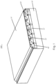
- Fig. 1 shows a schematic perspective view of the base station antenna 100 according to the first embodiment of the present disclosure, and also shows the internal structure of the base station antenna 100;
- Fig. 2 shows a schematic diagram of the base station antenna 100 without a radome 10;
- Fig. 3 shows a partial exemplary diagram of the base station antenna 100' in Fig. 1 and also shows the mounting scheme of radome supporting members 20 in the base station antenna 100.
- the base station antenna 100 may comprise a radio 30 (the so-called Radio module), a feed board 40, a radiating element array 50 mounted on the feed board 40, and the radome 10 arranged in front of the radiating element array 50.
- the radiating element array 50 may comprise a plurality of radiating elements, and each radiating element extends forward from the feed board 40.
- the radio 30 may feed radio frequency signals to the feed board 40 through a radio frequency connector or other conductors, and in turn feed the signals to the radiating element array 50 mounted on the feed board 40.
- the radio 30 may have a metal front wall 32 that faces the rear surface of the feed board 40 and metal side walls 34 that extend forward from the metal front wall 32.
- a housing recess 36 is defined by the metal front wall 32 and side walls 34 of the radio 30.
- the feed board 40 and the radiating element array 50 mounted thereon may be received in the housing recess 36.
- the feed board 40 may be installed on the metal front wall 32 by means of screw thread fasteners 38, such as screws.
- the metal front wall 32 may be configured as the "reflector" for the radiating element array 50, so as to reflect electromagnetic waves from the radiating element array 50 forward.
- the metal side walls 34 of the radio 30 may extend forward from the metal front wall 32 to the front of the feed board 40.
- the side circumference 12 of the radome 10 may, for example, be fixed on the extending side walls 34 of the radio 30 by means of screw thread fasteners 38.
- These extending metal side walls 34 may also have functions similar to metal fences that are traditionally disposed on the reflector.
- the size parameters of the metal side walls 34 may be adjusted so as to adjust the radiation pattern, for example, the front-to-back ratio from the radiating element array 50.
- Such base station antennas 100 with the radio 30 integrated in the antenna may be the aforementioned active antenna device, which may comprise one or a plurality of radiating element arrays that operate under fifth generation (5G or later) cellular network standards.
- the reflector that is generally disposed is replaced by the integrated radio 30, for example, the metal front wall 32 thereof, thereby effectively reducing the weight and/or cost of the base station antenna 100.
- the radome supporting members 20 may be directly fixed on the radio 30 and extend forward from the radio 30 to the radome 10 for supporting the radome 10.
- a plurality of rows of radome supporting members 20 arranged in a distributed manner may be mounted in the base station antenna 100, so as to support the radome 10 fully and reliably.
- the corresponding radome supporting members 20, for example, may be mounted between the radiating element array 50 to prevent the corresponding radiating elements from being damaged by the toppling of the radome 10.
- the radome supporting members 20 may extend forward from the metal front wall 32 of the radio 30 to the radome 10 until they are adjacent to or abutting the radome 10.
- each radome supporting member 20 may be integrated on the metal front wall 32 of the radio 30 - for example, through a manufacturing process such as die casting, thereby circumventing the complex mounting process of the radome supporting members 20 and saving costs.
- a series of through holes 42 for the radome supporting members 20 may be provided on the feed board 40.
- Each radome supporting member 20 may extend forward from the front wall 32 of the radio 30, pass through the corresponding through hole 42 and then further extend forward to the rear surface of the radome 10.
- the through holes 42 on the feed board 40 may be formed to conform to the radome supporting members 20 so as to effectively prevent the shaking of the radome supporting members 20 and further improve the mounting reliability of the radome supporting members 20.
- the radome supporting members 20 may be constructed as support posts. It should be understood that the radome supporting members 20 may be designed in diverse forms, for example, in a cylindrical shape, a prismatic shape, a frustum shape etc., and no further restriction is made here.
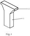
- Fig. 4 shows a modified design scheme of the radome supporting member 20.
- the radome supporting member 20 may have a columnar extending section 21 extending forward from the radio 30 and a supporting end 22 for directly supporting the radome 10.
- the supporting end 22 may have an enlarged cross-section.
- the supporting end 22 of the radome supporting member 20 may further extend forward with a gradually increasing cross-section from the extending section 21 to the supporting radome 10.
- the supporting strength and reliability may be increased by increasing the contact area of the radome supporting member 20.
- Figs. 5 to 7 describe in detail a base station antenna 100' according to a second embodiment of the present disclosure.
- Fig. 5 shows a schematic perspective view of the base station antenna 100' according to the second embodiment of the present disclosure, and also shows the internal structure of the base station antenna 100';
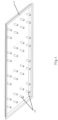
- Fig. 6 shows a schematic perspective view of a radome 10' of the base station antenna 100';
- Fig. 7 shows a partial exemplary diagram of the base station antenna 100', and shows the mounting scheme of radome supporting members 20' in the base station antenna 100'.
- the discussion above of the base station antenna 100 according to the first embodiment of the present disclosure may be equally applicable to the base station antenna 100 of the second embodiment of the present disclosure as long as they do not contradict each other, and it need not be described again here.
- the base station antenna 100' differs from the base station antenna 100 in the first embodiment in that, instead of fixing or integrating the radome supporting members 20 on the radio 30, the radome supporting members 20' are fixed or integrated on the radome 10' and extend rearward from the radome 10' to the supporting parts of the radome supporting members 20'.
- the radome supporting members 20' may be integrated on the rear surface of the radome 10' - for example, through a manufacturing process such as injection molding, thereby circumventing the complex mounting process of the radome supporting members 20' and saving costs. Therefore, the radome supporting members 20' may be constructed as plastic members. As shown in Fig. 5 , a plurality of rows of radome supporting members 20' arranged in a distributed manner are molded on the rear surface of the radome 10' and each radome supporting member 20' may extend rearward from the radome 10' to the supporting parts for the radome supporting members 20'. It should be understood that the radome supporting members 20' may also be fixed on the rear surface of the radome 10' through feasible mounting methods, for example, screw thread connection, plugging or bonding.
- the base station antenna 100' may be a traditional passive base station antenna, for example, a 4G antenna.
- the radio 30' is not integrated in the passive base station antenna, but a special reflector is mounted on the passive base station antenna.
- the base station antenna 100' may be realized as the aforementioned active antenna device, with the radio 30' being integrated therein.
- a specially disposed reflector is substituted by the integrated radio 30', for example, the metal front wall 32' thereof, thereby effectively maintaining the base station antenna 100' at a lower weight and/or lower cost.
- the supporting parts for the radome supporting members 20' may be disposed on any suitable position inside the base station antenna 100'.
- the supporting parts for the radome supporting members 20' may be disposed on the feed board 40'.
- the supporting parts for the radome supporting members 20' may be disposed on the radio 30'.
- the supporting parts for the radome supporting members 20' may be disposed on the reflector.
- the support part for the radome supporting members 20' may be disposed on the feed board 40'. That is to say, the radome supporting members 20' may extend rearward from the radome 10' to the supporting parts supported on the feed board 40'. As shown in Fig. 7 , the supporting parts may be disposed on the screw thread fasteners 38', for example, the connecting end 39' of the screws, of the feed board 40'. The radome supporting members 20' may extend rearward from the radome 10' to the connecting end 39' abutting the screw thread fasteners 38' such that the radome supporting members 20' are stably supported on the feed board 40'.
- the radome supporting members 20' do not need to pass through the feed board 40' again and thus may be realized with a shortened size, thereby saving materials and reducing the weight thereof.
- the screw thread fastener 38' may be aligned with [another] screw thread fastener 38' in the forward direction, thereby saving space occupied in the base station antenna 100'.
- Fig. 8 shows a modified design of the radome supporting member 20'.
- the rear end of each radome supporting member 20' may have a corresponding groove 21' for accommodating the connecting end 39' of the screw thread fastener 38', such that the rear end of the radome supporting member 20' may be spliced to the connecting end 39' of the screw thread fastener 38' in the form of shape fitting.
- the mounting reliability of the radome supporting members 20' may be further improved by effectively preventing the shaking of the radome supporting members 20'.
- the supporting parts for the radome supporting members 20' may be disposed on the radio 30', for example, on the metal front wall 32' thereof.
- a series of through holes (not shown) for the radome supporting members 20' may be provided on the feed board 40'.
- Each radome supporting member 20' may extend rearward from the radome 10', pass through the corresponding through hole and then further extend rearward to the radio 30', for example, the metal front wall 32' thereof.
- a groove (not shown) for accommodating the rear end of the radome supporting member 20' may be provided on the metal front wall 32' of the radio 30', thereby effectively prevent the shaking of the radome supporting member 20' and further improve the mounting reliability of the radome supporting member 20'.
Landscapes
- Engineering & Computer Science (AREA)
- Computer Networks & Wireless Communication (AREA)
- Details Of Aerials (AREA)
Applications Claiming Priority (1)
| Application Number | Priority Date | Filing Date | Title |
|---|---|---|---|
| CN202210202034.3A CN116742332A (zh) | 2022-03-03 | 2022-03-03 | 基站天线 |
Publications (1)
| Publication Number | Publication Date |
|---|---|
| EP4239792A1 true EP4239792A1 (de) | 2023-09-06 |
Family
ID=85477913
Family Applications (1)
| Application Number | Title | Priority Date | Filing Date |
|---|---|---|---|
| EP23160023.0A Pending EP4239792A1 (de) | 2022-03-03 | 2023-03-03 | Basisstationsantenne |
Country Status (3)
| Country | Link |
|---|---|
| US (1) | US12418104B2 (de) |
| EP (1) | EP4239792A1 (de) |
| CN (1) | CN116742332A (de) |
Citations (3)
| Publication number | Priority date | Publication date | Assignee | Title |
|---|---|---|---|---|
| CN205992589U (zh) * | 2016-08-29 | 2017-03-01 | 广东通宇通讯股份有限公司 | 一种天线罩支撑垫块 |
| CN206546874U (zh) * | 2016-11-23 | 2017-10-10 | 广东通宇通讯股份有限公司 | 基站天线用的支撑装置、支撑组件及支撑垫块 |
| US20210075092A1 (en) * | 2019-09-11 | 2021-03-11 | Commscope Technologies Llc | Base station antenna |
Family Cites Families (5)
| Publication number | Priority date | Publication date | Assignee | Title |
|---|---|---|---|---|
| US6069590A (en) * | 1998-02-20 | 2000-05-30 | Ems Technologies, Inc. | System and method for increasing the isolation characteristic of an antenna |
| DE102015002441A1 (de) * | 2015-02-26 | 2016-09-01 | Kathrein-Werke Kg | Radom sowie zugehörige Mobilfunkantenne und Verfahren zur Herstellung des Radoms oder der Mobilfunkantenne |
| US10601120B2 (en) * | 2017-05-17 | 2020-03-24 | Commscope Technologies Llc | Base station antennas having reflector assemblies with RF chokes |
| US12218425B2 (en) * | 2020-04-28 | 2025-02-04 | Outdoor Wireless Networks LLC | Base station antennas having reflector assemblies including a nonmetallic substrate having a metallic layer thereon |
| CN116345119A (zh) * | 2021-12-23 | 2023-06-27 | 康普技术有限责任公司 | 集成式基站天线 |
-
2022
- 2022-03-03 CN CN202210202034.3A patent/CN116742332A/zh active Pending
-
2023
- 2023-02-20 US US18/171,515 patent/US12418104B2/en active Active
- 2023-03-03 EP EP23160023.0A patent/EP4239792A1/de active Pending
Patent Citations (3)
| Publication number | Priority date | Publication date | Assignee | Title |
|---|---|---|---|---|
| CN205992589U (zh) * | 2016-08-29 | 2017-03-01 | 广东通宇通讯股份有限公司 | 一种天线罩支撑垫块 |
| CN206546874U (zh) * | 2016-11-23 | 2017-10-10 | 广东通宇通讯股份有限公司 | 基站天线用的支撑装置、支撑组件及支撑垫块 |
| US20210075092A1 (en) * | 2019-09-11 | 2021-03-11 | Commscope Technologies Llc | Base station antenna |
Also Published As
| Publication number | Publication date |
|---|---|
| US20230282971A1 (en) | 2023-09-07 |
| US12418104B2 (en) | 2025-09-16 |
| CN116742332A (zh) | 2023-09-12 |
Similar Documents
| Publication | Publication Date | Title |
|---|---|---|
| CN108511913B (zh) | 基站天线及其双极化天线振子 | |
| KR101095139B1 (ko) | 무선 이동 통신 안테나용 반사기 | |
| US9323877B2 (en) | Beam-steered wide bandwidth electromagnetic band gap antenna | |
| JP7399239B2 (ja) | 車載用アンテナ装置 | |
| US8508421B2 (en) | Hardened wave-guide antenna | |
| EP3828998B1 (de) | Endgerät | |
| US12136767B2 (en) | Antenna assembly and base station antenna | |
| US11962066B2 (en) | Terminal device | |
| US20060109193A1 (en) | Base station panel antenna with dual-polarized radiating elements and shaped reflector | |
| CN110911837B (zh) | 集成滤波器的天线 | |
| EP4239792A1 (de) | Basisstationsantenne | |
| US12603431B2 (en) | Antenna element and antenna array | |
| EP2472670A1 (de) | Antennenvorrichtung | |
| JP2010118778A (ja) | 平面アンテナ及びレーダ装置 | |
| JP6837932B2 (ja) | アンテナ | |
| CN120435801A (zh) | 天线和扇区框架安装系统 | |
| CN113451733B (zh) | 一种高圆度的车载测试终端天线 | |
| CN210926296U (zh) | 基站天线装置及移动通信网络系统 | |
| JP7506675B2 (ja) | 車両用アレイアンテナ | |
| JP4229006B2 (ja) | 統合アンテナ | |
| US20240006771A1 (en) | Antenna assembly and base station antenna | |
| CN117652061A (zh) | 用于电子装置的天线装置 | |
| KR102862580B1 (ko) | 마름모 형태의 다수개 방사패치를 활용한 위상배열 안테나 | |
| CN223911846U (zh) | 用于基站天线的天线罩和基站天线 | |
| KR102414079B1 (ko) | 로우 프로파일 이중 편파 안테나 |
Legal Events
| Date | Code | Title | Description |
|---|---|---|---|
| PUAI | Public reference made under article 153(3) epc to a published international application that has entered the european phase |
Free format text: ORIGINAL CODE: 0009012 |
|
| STAA | Information on the status of an ep patent application or granted ep patent |
Free format text: STATUS: REQUEST FOR EXAMINATION WAS MADE |
|
| 17P | Request for examination filed |
Effective date: 20230303 |
|
| AK | Designated contracting states |
Kind code of ref document: A1 Designated state(s): AL AT BE BG CH CY CZ DE DK EE ES FI FR GB GR HR HU IE IS IT LI LT LU LV MC ME MK MT NL NO PL PT RO RS SE SI SK SM TR |
|
| RAP3 | Party data changed (applicant data changed or rights of an application transferred) |
Owner name: COMMSCOPE TECHNOLOGIES LLC |
|
| RAP1 | Party data changed (applicant data changed or rights of an application transferred) |
Owner name: OUTDOOR WIRELESS NETWORKS LLC |
|
| GRAP | Despatch of communication of intention to grant a patent |
Free format text: ORIGINAL CODE: EPIDOSNIGR1 |
|
| STAA | Information on the status of an ep patent application or granted ep patent |
Free format text: STATUS: GRANT OF PATENT IS INTENDED |