EP4239765A1 - Housing for battery box, box of battery, battery, and power-consuming device - Google Patents
Housing for battery box, box of battery, battery, and power-consuming device Download PDFInfo
- Publication number
- EP4239765A1 EP4239765A1 EP22874251.6A EP22874251A EP4239765A1 EP 4239765 A1 EP4239765 A1 EP 4239765A1 EP 22874251 A EP22874251 A EP 22874251A EP 4239765 A1 EP4239765 A1 EP 4239765A1
- Authority
- EP
- European Patent Office
- Prior art keywords
- casing
- battery
- assembly bracket
- elastic member
- assembly
- Prior art date
- Legal status (The legal status is an assumption and is not a legal conclusion. Google has not performed a legal analysis and makes no representation as to the accuracy of the status listed.)
- Pending
Links
- 238000000034 method Methods 0.000 abstract description 18
- 230000008569 process Effects 0.000 abstract description 7
- 238000010586 diagram Methods 0.000 description 12
- 229910000838 Al alloy Inorganic materials 0.000 description 5
- XEEYBQQBJWHFJM-UHFFFAOYSA-N Iron Chemical compound [Fe] XEEYBQQBJWHFJM-UHFFFAOYSA-N 0.000 description 4
- 230000009471 action Effects 0.000 description 4
- 239000013543 active substance Substances 0.000 description 4
- 229910052782 aluminium Inorganic materials 0.000 description 4
- XAGFODPZIPBFFR-UHFFFAOYSA-N aluminium Chemical compound [Al] XAGFODPZIPBFFR-UHFFFAOYSA-N 0.000 description 4
- 239000012212 insulator Substances 0.000 description 3
- 239000000463 material Substances 0.000 description 3
- 239000004033 plastic Substances 0.000 description 3
- 238000003466 welding Methods 0.000 description 3
- RYGMFSIKBFXOCR-UHFFFAOYSA-N Copper Chemical compound [Cu] RYGMFSIKBFXOCR-UHFFFAOYSA-N 0.000 description 2
- 238000004891 communication Methods 0.000 description 2
- 230000006835 compression Effects 0.000 description 2
- 238000007906 compression Methods 0.000 description 2
- 229910052802 copper Inorganic materials 0.000 description 2
- 239000010949 copper Substances 0.000 description 2
- 230000005489 elastic deformation Effects 0.000 description 2
- 239000003792 electrolyte Substances 0.000 description 2
- 238000001125 extrusion Methods 0.000 description 2
- 229910052742 iron Inorganic materials 0.000 description 2
- 239000007769 metal material Substances 0.000 description 2
- VNWKTOKETHGBQD-UHFFFAOYSA-N methane Chemical compound C VNWKTOKETHGBQD-UHFFFAOYSA-N 0.000 description 2
- 239000010935 stainless steel Substances 0.000 description 2
- 229910001220 stainless steel Inorganic materials 0.000 description 2
- HBBGRARXTFLTSG-UHFFFAOYSA-N Lithium ion Chemical compound [Li+] HBBGRARXTFLTSG-UHFFFAOYSA-N 0.000 description 1
- JLVVSXFLKOJNIY-UHFFFAOYSA-N Magnesium ion Chemical compound [Mg+2] JLVVSXFLKOJNIY-UHFFFAOYSA-N 0.000 description 1
- FKNQFGJONOIPTF-UHFFFAOYSA-N Sodium cation Chemical compound [Na+] FKNQFGJONOIPTF-UHFFFAOYSA-N 0.000 description 1
- 229910000831 Steel Inorganic materials 0.000 description 1
- 230000000712 assembly Effects 0.000 description 1
- 238000000429 assembly Methods 0.000 description 1
- 238000005452 bending Methods 0.000 description 1
- 230000008859 change Effects 0.000 description 1
- 238000010276 construction Methods 0.000 description 1
- 238000007599 discharging Methods 0.000 description 1
- 238000003487 electrochemical reaction Methods 0.000 description 1
- 239000002803 fossil fuel Substances 0.000 description 1
- 230000014509 gene expression Effects 0.000 description 1
- 230000036541 health Effects 0.000 description 1
- 239000007788 liquid Substances 0.000 description 1
- 229910001416 lithium ion Inorganic materials 0.000 description 1
- 229910001425 magnesium ion Inorganic materials 0.000 description 1
- 230000007246 mechanism Effects 0.000 description 1
- 238000012986 modification Methods 0.000 description 1
- 230000004048 modification Effects 0.000 description 1
- 238000012544 monitoring process Methods 0.000 description 1
- 239000003345 natural gas Substances 0.000 description 1
- 238000004806 packaging method and process Methods 0.000 description 1
- 229910001415 sodium ion Inorganic materials 0.000 description 1
- 239000010959 steel Substances 0.000 description 1
- 238000004804 winding Methods 0.000 description 1
Images



Classifications
-
- H—ELECTRICITY
- H01—ELECTRIC ELEMENTS
- H01M—PROCESSES OR MEANS, e.g. BATTERIES, FOR THE DIRECT CONVERSION OF CHEMICAL ENERGY INTO ELECTRICAL ENERGY
- H01M50/00—Constructional details or processes of manufacture of the non-active parts of electrochemical cells other than fuel cells, e.g. hybrid cells
- H01M50/20—Mountings; Secondary casings or frames; Racks, modules or packs; Suspension devices; Shock absorbers; Transport or carrying devices; Holders
- H01M50/204—Racks, modules or packs for multiple batteries or multiple cells
- H01M50/207—Racks, modules or packs for multiple batteries or multiple cells characterised by their shape
- H01M50/209—Racks, modules or packs for multiple batteries or multiple cells characterised by their shape adapted for prismatic or rectangular cells
-
- H—ELECTRICITY
- H01—ELECTRIC ELEMENTS
- H01M—PROCESSES OR MEANS, e.g. BATTERIES, FOR THE DIRECT CONVERSION OF CHEMICAL ENERGY INTO ELECTRICAL ENERGY
- H01M50/00—Constructional details or processes of manufacture of the non-active parts of electrochemical cells other than fuel cells, e.g. hybrid cells
- H01M50/20—Mountings; Secondary casings or frames; Racks, modules or packs; Suspension devices; Shock absorbers; Transport or carrying devices; Holders
- H01M50/244—Secondary casings; Racks; Suspension devices; Carrying devices; Holders characterised by their mounting method
-
- H—ELECTRICITY
- H01—ELECTRIC ELEMENTS
- H01M—PROCESSES OR MEANS, e.g. BATTERIES, FOR THE DIRECT CONVERSION OF CHEMICAL ENERGY INTO ELECTRICAL ENERGY
- H01M10/00—Secondary cells; Manufacture thereof
- H01M10/42—Methods or arrangements for servicing or maintenance of secondary cells or secondary half-cells
- H01M10/425—Structural combination with electronic components, e.g. electronic circuits integrated to the outside of the casing
-
- H—ELECTRICITY
- H01—ELECTRIC ELEMENTS
- H01M—PROCESSES OR MEANS, e.g. BATTERIES, FOR THE DIRECT CONVERSION OF CHEMICAL ENERGY INTO ELECTRICAL ENERGY
- H01M50/00—Constructional details or processes of manufacture of the non-active parts of electrochemical cells other than fuel cells, e.g. hybrid cells
- H01M50/20—Mountings; Secondary casings or frames; Racks, modules or packs; Suspension devices; Shock absorbers; Transport or carrying devices; Holders
- H01M50/204—Racks, modules or packs for multiple batteries or multiple cells
-
- H—ELECTRICITY
- H01—ELECTRIC ELEMENTS
- H01M—PROCESSES OR MEANS, e.g. BATTERIES, FOR THE DIRECT CONVERSION OF CHEMICAL ENERGY INTO ELECTRICAL ENERGY
- H01M50/00—Constructional details or processes of manufacture of the non-active parts of electrochemical cells other than fuel cells, e.g. hybrid cells
- H01M50/20—Mountings; Secondary casings or frames; Racks, modules or packs; Suspension devices; Shock absorbers; Transport or carrying devices; Holders
- H01M50/233—Mountings; Secondary casings or frames; Racks, modules or packs; Suspension devices; Shock absorbers; Transport or carrying devices; Holders characterised by physical properties of casings or racks, e.g. dimensions
- H01M50/242—Mountings; Secondary casings or frames; Racks, modules or packs; Suspension devices; Shock absorbers; Transport or carrying devices; Holders characterised by physical properties of casings or racks, e.g. dimensions adapted for protecting batteries against vibrations, collision impact or swelling
-
- H—ELECTRICITY
- H01—ELECTRIC ELEMENTS
- H01M—PROCESSES OR MEANS, e.g. BATTERIES, FOR THE DIRECT CONVERSION OF CHEMICAL ENERGY INTO ELECTRICAL ENERGY
- H01M50/00—Constructional details or processes of manufacture of the non-active parts of electrochemical cells other than fuel cells, e.g. hybrid cells
- H01M50/20—Mountings; Secondary casings or frames; Racks, modules or packs; Suspension devices; Shock absorbers; Transport or carrying devices; Holders
- H01M50/249—Mountings; Secondary casings or frames; Racks, modules or packs; Suspension devices; Shock absorbers; Transport or carrying devices; Holders specially adapted for aircraft or vehicles, e.g. cars or trains
-
- H—ELECTRICITY
- H01—ELECTRIC ELEMENTS
- H01M—PROCESSES OR MEANS, e.g. BATTERIES, FOR THE DIRECT CONVERSION OF CHEMICAL ENERGY INTO ELECTRICAL ENERGY
- H01M50/00—Constructional details or processes of manufacture of the non-active parts of electrochemical cells other than fuel cells, e.g. hybrid cells
- H01M50/20—Mountings; Secondary casings or frames; Racks, modules or packs; Suspension devices; Shock absorbers; Transport or carrying devices; Holders
- H01M50/262—Mountings; Secondary casings or frames; Racks, modules or packs; Suspension devices; Shock absorbers; Transport or carrying devices; Holders with fastening means, e.g. locks
-
- H—ELECTRICITY
- H01—ELECTRIC ELEMENTS
- H01M—PROCESSES OR MEANS, e.g. BATTERIES, FOR THE DIRECT CONVERSION OF CHEMICAL ENERGY INTO ELECTRICAL ENERGY
- H01M10/00—Secondary cells; Manufacture thereof
- H01M10/42—Methods or arrangements for servicing or maintenance of secondary cells or secondary half-cells
- H01M10/425—Structural combination with electronic components, e.g. electronic circuits integrated to the outside of the casing
- H01M2010/4271—Battery management systems including electronic circuits, e.g. control of current or voltage to keep battery in healthy state, cell balancing
-
- H—ELECTRICITY
- H01—ELECTRIC ELEMENTS
- H01M—PROCESSES OR MEANS, e.g. BATTERIES, FOR THE DIRECT CONVERSION OF CHEMICAL ENERGY INTO ELECTRICAL ENERGY
- H01M2220/00—Batteries for particular applications
- H01M2220/20—Batteries in motive systems, e.g. vehicle, ship, plane
-
- Y—GENERAL TAGGING OF NEW TECHNOLOGICAL DEVELOPMENTS; GENERAL TAGGING OF CROSS-SECTIONAL TECHNOLOGIES SPANNING OVER SEVERAL SECTIONS OF THE IPC; TECHNICAL SUBJECTS COVERED BY FORMER USPC CROSS-REFERENCE ART COLLECTIONS [XRACs] AND DIGESTS
- Y02—TECHNOLOGIES OR APPLICATIONS FOR MITIGATION OR ADAPTATION AGAINST CLIMATE CHANGE
- Y02E—REDUCTION OF GREENHOUSE GAS [GHG] EMISSIONS, RELATED TO ENERGY GENERATION, TRANSMISSION OR DISTRIBUTION
- Y02E60/00—Enabling technologies; Technologies with a potential or indirect contribution to GHG emissions mitigation
- Y02E60/10—Energy storage using batteries
Definitions
- Embodiments of this application relate to the field of batteries, and in particular, to a casing for battery box, a battery box, a battery, and an electric apparatus.
- a BMS Battery Management System, battery management system
- a casing for the BMS cannot be securely fixed, the casing is apt to shake on an assembly bracket, and the assembly method is monotonous, thereby causing low assembly efficiency.
- some embodiments of this application provide a casing for battery box, a battery box, a battery, and an electric apparatus, which can improve assembly efficiency, avoid shaking of the casing after being assembled on the bracket, and enrich assembly methods.
- a casing for battery box including: a body for accommodating a battery management system and a mounting member fixed on the body, where the mounting member includes a first end and a second end at opposite locations, the first end is provided with an elastic member, the second end is provided with a clamping portion, the clamping portion is configured to be clamped to an assembly bracket, and the elastic member is configured to generate a rebound force under limitation of the assembly bracket, so as to fix the mounting member at a location on the assembly bracket.
- the elastic member generates the rebound force under the limitation of the assembly bracket, and even if the casing vibrates during use, the rebound force can counteract a force generated due to the vibration, so that the casing is firmly fixed on the assembly bracket, thereby preventing the casing from shaking on the assembly bracket, improving mounting stability of the casing, and avoiding a safety risk.
- the elastic member includes a connecting end configured to be connected to a first end of a mounting member; and a free end, where the free end is bent toward the mounting member, and at least part of the elastic member is configured to abut against the assembly bracket to generate a rebound force.
- the free end of the elastic member is bent toward the mounting member.
- the casing is pushed to specific extent from the trough opening of the assembly trough to the trough bottom, at least part of the outer wall of the bent part of the elastic member is in contact with the trough bottom, and the elastic member begins to deform to generate the rebound force.
- the location of the casing on the assembly bracket can be fixed.
- the free end has a straight section, and a side, farther away from the mounting member, of the straight section is configured to abut against the assembly bracket.
- a straight section is disposed at the free end, and the straight section abuts against the trough bottom of the assembly bracket, which can increase an abutting surface, reduce a risk of slipping when the free end abuts against the trough bottom, and reduce a probability of abutting failure, thereby improving assembly stability of the casing on the assembly bracket.
- the first end is further provided with a limiting portion, and the limiting portion is configured to limit the curvature of the elastic member.
- the limiting portion is located between the first end of the mounting member and the free end of the elastic member.
- the free end is in contact with the limiting portion instead of the first end of the mounting member, thereby avoiding wear on the first end of the mounting member.
- the limiting portion is closer to the free end than the first end, which reduces a movable range of the free end of the elastic member, so that the curvature of the limiting portion is further limited to avoid a failure of the elastic member caused by excessive deformation.
- the elastic member when L and D satisfy the foregoing multiple relationship, the elastic member can be deformed within an elastic deformation capacity range of the elastic member, and the rebound force generated by the elastic member can keep the location of the casing on the assembly bracket unchanged.
- the casing further includes a limiting plate, where two opposite plate surfaces of the limiting plate are respectively fixed on the body and the mounting member, and at least part of the limiting plate is configured to abut against an inner wall of the assembly bracket to fix the casing at a location on the assembly bracket.
- the two limiting plates can have a limiting function, to avoid a decrease in assembly stability of the casing on the assembly bracket caused because the casing moves in a direction of a line connecting the two opposite walls of the assembly bracket.
- the mounting member has at least one notch along an extension direction of the mounting member.
- weight of the mounting member can be reduced, so that weight of the casing can be reduced.
- surface areas of the two opposite surfaces of the mounting member that are parallel to the trough wall can be reduced, and therefore, a contact area between the mounting member and the trough wall can be reduced, and a frictional force between the mounting member and the trough wall can be reduced when the casing is pushed into the assembly trough, to avoid wear on the mounting member and the trough wall, which can also reduce the pushing force to facilitate pushing of the casing into the assembly trough, thereby improving assembly efficiency of the casing.
- a battery box including an assembly bracket and the casing in the first aspect, where the casing is assembled on the assembly bracket.
- a battery including a battery cell and the box in the second aspect, where the box is configured to accommodate the battery cell.
- an electric apparatus including the battery in the third aspect, where the battery is configured to supply electric energy.
- the location of the mounting member on the assembly bracket is fixed, so that the location of the casing on the assembly bracket is fixed.
- a new assembly method is provided for the casing, so that assembly methods of the casing are enriched.
- no additional accessory is required, and the casing only needs to be pushed into the assembly trough for clamping, thereby achieving a simple mounting process and high assembly efficiency, and saving manpower.
- the elastic member generates the rebound force under the limitation of the assembly bracket, and even if the casing vibrates during use, the rebound force can counteract a force generated due to the vibration, so that the casing is firmly fixed on the assembly bracket, thereby preventing the casing from shaking on the assembly bracket, improving mounting stability of the casing, and avoiding a safety risk.
- a and/or B may indicate three cases: presence of only A; presence of both A and B; and presence of only B.
- a character "/" in this specification generally indicates an "or" relationship between contextually associated obj ects.
- orientations or positional relationships indicated by the terms “center”, “longitudinal”, “transverse”, “length”, “width”, “thickness”, “upper”, “lower”, “front”, “rear”, “left”, “right”, “perpendicular”, “horizontal”, “top”, “bottom”, “inside”, “outside”, “clockwise”, “counterclockwise”, “axial”, “radial”, “circumferential”, and the like are based on the orientations or positional relationships as shown in the accompanying drawings.
- plural means more than two (including two).
- multiple groups means more than two groups (including two groups).
- connection should be understood broadly.
- “connected” or “connection” of a mechanical structure may indicate physical connection.
- the physical connection may be fixed connection, for example, fixed connection by using a fixing member such as a screw, a bolt or other fixing members; or the physical connection may be detachable connection, for example, connection by mutual clamping or clamping; or the physical connection may be an integral connection, for example, connection by welding, bonding or integral forming.
- Connected or “connection” of a circuit structure may indicate physical connection, and may also indicate electrical connection or signal connection, for example, may be direct connection, that is, the physical connection, may be indirect connection by using at least one component in between as long as circuit communication is implemented, and may also be communication between two components; and the signal connection may be signal connection by using a circuit, and may also be signal connection by using a media medium, such as a radio wave.
- a media medium such as a radio wave
- the battery mentioned in the embodiments of this application is a single physical module that includes one or more battery cells for providing a higher voltage and capacity.
- the battery mentioned in this application may include a battery module, a battery pack, or the like.
- the battery module, the battery pack, and the like may be collectively referred to as the battery.
- a battery typically includes a box configured to enclose one or more battery cells.
- the box includes a casing and an assembly bracket for assembling the casing, and the casing can accommodate a battery management system.
- the box can prevent liquids or other foreign matter from affecting charging or discharging of the battery cell.
- mounting portions are disposed at a plurality of locations on a side wall of the casing, each mounting portion is provided with a first threaded hole, and a second threaded hole is disposed at a location, opposite each first threaded hole, of the assembly bracket.
- a plurality of bolts are prepared, and after an end of each bolt is sequentially passed through the first threaded hole and the second threaded hole at opposite locations, the bolt is locked with a nut to achieve assembly of the casing on the assembly bracket. It can be seen that in the related art, the plurality of bolts and a plurality of nuts are required to fix the casing on the assembly bracket, and a large number of accessories are required.
- the bolt and the nut need to be manually mounted via many mounting processes, thereby causing low assembly efficiency and requiring a large amount of manpower.
- the battery and the casing in the battery vibrate during use.
- the bolt and the nut for fixing the casing are apt to loosen, and as a result, the casing is apt to shake on the assembly bracket, thereby causing a safety risk.
- an embodiment of this application provides a casing for battery box, and the casing includes a body for accommodating a battery management system and a mounting member fixed on the body.
- a first end of the mounting member is provided with an elastic member
- a second end is provided with a clamping portion.
- the clamping portion can be clamped to the assembly bracket, an elastic portion can generate a rebound force under limitation of the assembly bracket, and under action of the rebound force, the mounting member is fixed at a location on the assembly bracket, so that the casing is fixed at a location on the assembly bracket.
- the elastic portion generates the rebound force under the limitation of the assembly bracket, and even if the casing vibrates during use, the rebound force can counteract a force generated due to the vibration, so that the mounting member is firmly fixed on the assembly bracket, thereby preventing the casing from shaking on the assembly bracket, improving mounting stability of the casing, and avoiding a safety risk.
- the casing 5 disclosed in this embodiment of this application may be configured to accommodate a battery management system, and the battery management system may be used without limitation in an electric apparatus such as a vehicle 1, a ship, or an aircraft.
- An embodiment of this application provides an electric apparatus that uses a battery 100 as a power supply.
- the battery includes a battery management system.
- the electric apparatus may be, but is not limited to, a mobile phone, a tablet, a laptop computer, an electric toy, an electric bicycle, an electric car, a ship, or a spacecraft.
- the electric toy may be a fixed or mobile electric toy, for example, a game console, an electric toy car, an electric toy ship, and an electric toy airplane.
- the spacecraft may include an airplane, a rocket, a space shuttle, a spaceship, and the like.
- the electric apparatus of an embodiment of the application being a vehicle 1 is used as an example for description of the following embodiments.
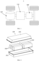
- FIG. 1 is a schematic structural diagram of a vehicle 1 according to some embodiments of this application.
- the vehicle 1 may be an oil-fueled vehicle, a gas-powered vehicle, or a new energy vehicle.
- the new energy vehicle may be a battery electric vehicle, a hybrid electric vehicle, an extended-range electric vehicle, or the like.
- the vehicle 1 is provided with a battery 100 inside, where the battery 100 may be disposed at the bottom, front or rear of the vehicle 1.
- the battery 100 may be configured to supply power to the vehicle 1.
- the battery 100 may be used as an operational power supply for the vehicle 1.
- the vehicle 1 may further include a controller 110 and a motor 120, where the controller 110 is configured to control the battery 100 to supply power to the motor 120, for example, to satisfy power needs of start, navigation, and driving of the vehicle 1.
- the battery 100 can be used as not only the operational power supply for the vehicle 1 but also a driving power supply for the vehicle 1, replacing or partially replacing fossil fuel or natural gas to provide driving traction for the vehicle 1.
- the battery 100 may include a plurality of battery modules 300 electrically connected to each other.
- the battery includes a first box 201, a second box 202, and a plurality of battery modules 300.
- the first box 201 and the second box 202 are buckled with each other.
- the plurality of battery modules 300 are arranged in space enclosed by the first box 201 and the second box 202.
- the first box 201 and the second box 202 may be made of aluminum, aluminum alloy, or another metal material, and the first box 201 and the second box 202 are hermetically connected.
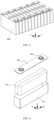
- FIG. 3 is a schematic structural diagram of a battery module 300 according to an embodiment of this application.
- the battery module 300 may include a plurality of battery cells 400.
- the plurality of battery cells 400 may first be connected in series, parallel, or series-parallel to constitute battery modules, and then a plurality of battery modules 300 may be connected in series, parallel, or series-parallel to constitute a battery 100.
- the battery cell 400 may include a lithium-ion battery, a sodium-ion battery, a magnesium-ion battery, or the like. This is not limited in the embodiments of this application.
- the battery cell 400 may be cylindrical, flat, rectangular, or another shape, and this is also not limited in the embodiments of this application.
- the battery cells 400 are usually categorized into three types depending on their packaging: a cylinder battery cell 400, a prismatic battery cell 400, and a pouch battery cell 400, and this is also not limited in the embodiments of this application. However, for brevity of description, the following embodiments are all described by taking a prismatic cell 400 as an example.
- FIG. 4 is a schematic structural exploded view of a battery cell 400 according to some embodiments of this application;
- the battery cell 400 refers to a smallest unit constituting a battery.
- the battery cell 400 includes an end cover 402, a housing 401, and an electrode assembly 403.
- the end cover 402 refers to a component that covers an opening of the housing 401 to isolate an internal environment of the battery cell 400 from an external environment.
- a shape of the end cover 402 is not limited and may be adapted to a shape of the housing 401 to fit the housing 401.
- the end cover 402 may be made of a material with specified hardness and strength (for example, aluminum alloy), so that the end cover 402 is less likely to deform when subjected to extrusion and collision, allowing the battery cell 400 to have higher structural strength and enhanced safety performance.
- a functional component such as an electrode terminal 402b may be provided on the end cover 402.
- the electrode terminal 402b may be configured to be electrically connected to the electrode assembly 403 for outputting or inputting electric energy of the battery cell 400.
- the end cover 402 may further be provided with a pressure relief mechanism for releasing internal pressure when the internal pressure or temperature of the battery cell 400 reaches a threshold.
- the end cover 402 may also be made of various materials, such as copper, iron, aluminum, stainless steel, aluminum alloy, and plastic, which are not particularly limited in the embodiments of this application.
- an insulator may also be provided at an inner side of the end cover 402. The insulator may be configured to isolate an electrically connected component in the housing 401 from the end cover 402 to reduce a risk of short circuit.
- the insulator may be made of plastic, rubber, or the like.
- the housing 401 is an assembly configured to fit the end cover 402 to form an internal environment of the battery cell 400, where the formed internal environment can be used to accommodate the electrode assembly 403, an electrolyte (not shown in the figure), and another component.
- the housing 401 and the end cover 402 may be separate components, an opening may be provided on the housing 401, and the end cover 402 covers the opening to form the internal environment of the battery cell 400.
- the end cover 402 and the housing 401 are not limited and may alternatively be integrated. Specifically, the end cover 402 and the housing 401 may form a shared connection surface before other components are disposed inside the housing, and then the housing 401 is covered with the end cover 402 when the inside of the housing 401 needs to be enclosed.
- the housing 401 may be of various shapes and sizes, for example, a cuboid shape, a cylindrical shape, and a hexagonal prism shape. Specifically, a shape of the housing 401 may be determined according to a specific shape and size of the electrode assembly 403.
- the housing 401 may be made of various materials, such as copper, iron, aluminum, stainless steel, aluminum alloy, and plastic, which are not particularly limited in the embodiments of this application.
- the electrode assembly 403 is a component in which electrochemical reactions occur in the battery cell 400.
- the housing 401 may include one or more electrode assemblies 403.
- the electrode assembly 403 is mainly formed by winding or stacking a positive electrode plate and a negative electrode plate, and a separator is generally disposed between the positive electrode plate and the negative electrode plate.
- the parts with an active substance on the positive electrode plate and the negative electrode plate constitute a body portion of the cell assembly, and the parts without the active substance on the positive electrode plate and the negative electrode plate respectively constitute tabs (not shown in the figure).
- a positive tab and a negative tab may both be located at one end of the body portion or be located at two ends of the body portion respectively.
- a positive electrode active substance and a negative electrode active substance react with an electrolyte, and the tabs are connected to the electrode terminals to form a current loop.
- FIG. 5 is a schematic structural diagram of a casing 5 according to an embodiment of this application.
- the casing 5 includes a body 51 for accommodating a battery management system and a mounting member 52 fixed on the body 51.
- the mounting member 52 includes a first end and a second end at opposite locations, the first end is provided with an elastic member 521, the second end is provided with a clamping portion 522, the clamping portion 522 is configured to be clamped to an assembly bracket 6, and the elastic member 521 is configured to generate a rebound force under limitation of the assembly bracket 6, so as to fix the mounting member 52 at a location on the assembly bracket 6.
- the body 51 includes a first housing and a second housing, and the first housing and the second housing are snap-fitted together to form space for accommodating a battery management system.
- the first housing may be a plate-shaped structure
- the second housing may be a hollow structure with an end open, and the first housing is snap-fitted at the open side of the second housing, so that the first housing and the second housing jointly define the space for accommodating the battery management system; or the first housing and the second housing may both be hollow structures with an end open, and the open side of the first housing is snap-fitted at the open side of the second housing.
- the first housing and the second housing may be made of aluminum, aluminum alloy, or another metal material, and the first housing and the second housing are hermetically connected.
- the first housing and the second housing can be formed via extrusion molding, to facilitate forming of the first housing and the second housing of different sizes.
- the body 51 is a rectangular housing structure, the body 51 is enclosed by two surfaces and four side walls at opposite locations, and the four side walls include two pairs of side walls at opposite locations.
- the two mounting members 52 There may be two mounting members 52, and the two mounting members 52 are respectively fixed on the two side walls of the body 51 at opposite locations, and the mounting members 52 can be disposed parallel to the side walls of the body 51 on which the mounting members 52 are fixed.
- the two mounting members 52 on the two sides of the body 51 may or may not be on the same plane, which is not limited in this embodiment of this application.
- the mounting member 52 has a first end and a second end at opposite locations in an extension direction of the mounting member 52.
- first end is an end of the mounting member 52 that first comes into contact with the assembly bracket 6, and the second end is an end of the mounting member 52 that latter comes into contact with the assembly bracket 6.
- the assembly bracket 6 involved in this embodiment of this application has two walls at opposite locations, the two walls each are provided with an assembly trough 61, the assembly trough 61 has a trough opening 61a, a trough wall 61b, and a trough bottom 61c, and a slot 61d is provided at a location, closer to the trough opening 61a, on the trough wall 61b of the assembly trough 61.
- the assembly troughs 61 disposed on the two opposite walls of the assembly bracket 6 are opposite each other.
- the assembly troughs 61 disposed on the two opposite walls of the assembly bracket 6 may not be opposite each other, as long as it is ensured that when the casing 5 is mounted, the two mounting members 52 on the two sides of the body 51 can be respectively located in the two assembly troughs 61 of the assembly bracket 6.
- the mounting member 52 of the casing 5 is placed at a location of the trough opening 61a of the assembly trough 61, and a pushing force is applied to the casing 5 to push the casing 5 from the trough opening 61a to the trough bottom 61c.
- the elastic member 521 at the first end of the mounting member 52 comes into contact with the trough bottom 61c, and the trough bottom 61c limits the elastic member 521 and applies a force on the elastic member 521 toward the trough opening 61a.
- the elastic member 521 is compressed and deformed under the pushing force and limitation of the trough bottom 61c to generate the rebound force.
- the elastic member 521 As the pushing force is continuously applied, the elastic member 521 is further compressed, and the generated rebound force is further increased until the clamping portion 522 at the second end of the mounting member 52 is clamped into the slot 61d of the assembly trough 61. Application of the pushing force is stopped when the clamping portion 522 is clamped into the slot 61d. In this case, the elastic member 521 is still in a compressed state, and the rebound force of the elastic member 521 enables the elastic member 521 to press against the trough bottom 61c, and enables the clamping portion 522 to be clamped into the slot 61d tightly, so that a location of the mounting member 52 relative to the assembly trough 61 is fixed, thereby fixing the casing 5 on the assembly bracket 6.
- the elastic member 521 generates the rebound force under the limitation of the assembly bracket 6, and even if the casing 5 vibrates during use, the rebound force can counteract a force generated due to the vibration, so that the casing 5 is firmly fixed on the assembly bracket 6, thereby preventing the casing 5 from shaking on the assembly bracket 6, improving mounting stability of the casing 5, and avoiding a safety risk.
- the elastic member 521 may include a connecting end 521a and a free end 521b, the connecting end 521a is configured to be connected to the first end of the mounting member 52, and the free end 521b is configured to abut against the trough bottom 61c of the assembly trough 61 and move toward the connecting end 521a of the elastic member 521 under the limitation of the trough bottom 61c, so that the elastic member 521 is compressed to generate a rebound force.
- the elastic member 521 may be a spring. Parameters such as unfolded length and free height of the elastic member 521 can be set as required, as long as it is ensured that when the casing 5 is assembled on the assembly bracket 6, the rebound force generated by the elastic member 521 is sufficient to clamp the mounting member 52 in the assembly trough 61 tightly, which is not limited in this embodiment of this application.
- the unfolded length of the elastic member 521 refers to length of steel wire that needs to be wound to form the elastic member 521
- the free height of the elastic member 521 refers to height of the elastic member 521 under no external force.
- the free end 521b of the elastic member 521 abuts against the trough bottom 61c, and the elastic member 521 is compressed and deformed under the pushing force and limitation of the trough bottom 61c to generate the rebound force.
- the pushing force is continuously applied, the free end 521b moves toward the connecting end 521a, the elastic member 521 is further compressed, the rebound force is increased, and application of the pushing force is stopped when the clamping portion 522 is clamped into the slot 61d.
- the rebound force of the elastic member 521 enables the elastic member 521 to press against the trough bottom 61c, and enables the clamping portion 522 to be clamped into the slot 61d, so that a location of the mounting member 52 relative to the assembly trough 61 is fixed, thereby fixing the casing 5 on the assembly bracket 6.
- the elastic member 521 may include a connecting end 521a and a free end 521b, the connecting end 521a is configured to be connected to the first end of the mounting member 52, and the free end 521b is bent toward the mounting member 52, and at least part of the elastic member 521 is configured to abut against the assembly bracket 6 to generate the rebound force.
- the free end 521b of the elastic member 521 is bent toward the mounting member 52 to form a "C" shape shown in FIG. 7 in a natural state, and there is an opening 521c between the free end 521b and the connecting end 521a.
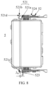
- the opening 521c of the elastic member 521 in FIG. 8 is slightly narrowed compared with that in FIG. 7 ; or if the amount of deformation is large, the opening 521c is more narrowed or even disappears, and as shown in FIG. 9 , the opening 521c of the elastic member 521 in FIG.
- the elastic member 521 may be an elastic tab.
- At least part of the elastic member 521 that abuts against the assembly bracket 6 may refer to a bent part between the free end 521b and the connecting end 521a, or a part, closer to the free end 521b, of the elastic member 521. More specifically, if a part between the free end 521b of the elastic member 521 and the connecting end 521a includes an inner wall and an outer wall, at least part of the elastic member 521 abutting against the assembly bracket 6 means that at least part of an outer wall of a bent part between the free end 521b of the elastic member 521 and the connecting end 521a is in contact with the trough bottom 61c.
- the inner wall refers to a wall in the bent part that faces toward the mounting member 52
- the outer wall refers to a wall in the bent part that faces away from the mounting member 52.
- the free end 521b of the elastic member 521 is bent toward the mounting member 52.
- the casing 5 is pushed to specific extent from the trough opening 61a of the assembly trough 61 to the trough bottom 61c, at least part of the outer wall of the bent part of the elastic member 521 is in contact with the trough bottom 61c, and the elastic member 521 begins to deform to generate the rebound force. Under action of the rebound force, the location of the casing 5 on the assembly bracket 6 can be fixed.
- the free end 521b has a straight section 521d, and a side, farther away from the mounting member 52, of the straight section 521d is configured to abut against the assembly bracket 6.
- Straightness is relative to bending.
- Straightness does not necessarily indicate a plane, but can alternatively indicate a straight cylindrical surface.
- a shape of a side, farther away from the mounting member 52, of the straight section 521d can be set based on a shape of the trough bottom 61c.
- the side, farther away from the mounting member 52, of the straight section 521d can be planar.
- the side, farther away from the mounting member 52, of the straight section 521d can be a straight cylindrical surface.
- the shape of the side, farther away from the mounting member 52, of the straight section 521d can be the same as the shape of the trough bottom 61c, so that when the side, farther away from the mounting member 52, of the straight section 521d abuts against the trough bottom 61c, an abutting area is relatively large, and an abutting failure due to slipping is unlikely to occur.
- Length of the straight section 521d can be set based on length of the trough bottom 61c of the assembly trough 61.
- the length of the straight section 521d can be equal to the length of the trough bottom 61c.
- the length of the straight section 521d may alternatively be slightly greater than the length of the trough bottom 61c, which is not limited in this embodiment of this application.
- a straight section 521d is disposed at the free end 521b, and the straight section 521d abuts against the trough bottom 61c of the assembly bracket 6, which can increase an abutting surface, reduce a risk of slipping when the free end 521b abuts against the trough bottom 61c, and reduce a probability of abutting failure, thereby improving assembly stability of the casing 5 on the assembly bracket 6.
- the side, closer to the mounting member 52, of the straight section 521d may be a planar structure.
- the free end 521b is in contact with the first end of the mounting member 52.
- the free end 521b being in contact with the first end of the mounting member 52 means that the side, closer to the mounting member 52, of the free end 521b is in contact with the first end of the mounting member 52.
- each part of the planar structure can be configured to be in contact with the first end of the mounting member 52, and after the side, closer to the mounting member 52, of the straight section 521d is in contact with the first end of the mounting member 52, a failure of the elastic member 521 caused by excessive deformation of the elastic member 521 can be limited.
- the side, closer to the mounting member 52, of the straight section 521d is set to be a planar structure, which can increase a limiting area of the side, closer to the mounting member 52, of the straight section 521d and avoid a failure of the elastic member 521 caused by a limitation failure of curvature of the elastic member 521 caused by a limitation failure of the side, closer to the mounting member 52, of the straight section 521d and the first end of the mounting member 52.
- the first end of the mounting member 52 is further provided with a limiting portion 523, and the limiting portion 523 is configured to limit the curvature of the elastic member 521.
- the limiting portion 523 and the mounting member 52 may be integrated, and in this case, the limiting portion 523 may be a bulge provided on the first end of the mounting member 52.
- the limiting portion 523 and the mounting member 52 may alternatively be formed separately, and the limiting portion 523 may be connected to the first end of the mounting member 52 via welding, screwing, or the like.
- the limiting portion 523 is disposed on the first end of the mounting member 52 and faces toward the free end 521b of the elastic member 521, that is, the limiting portion 523 is located between the first end of the mounting member 52 and the free end 521b of the elastic member 521.
- the free end 521b is in contact with the limiting portion 523 instead of the first end of the mounting member 52, thereby avoiding wear on the first end of the mounting member 52.
- the limiting portion 523 is closer to the free end 521b than the first end, which reduces a movable range of the free end 521b of the elastic member 521, so that the curvature of the limiting portion 523 is further limited to avoid a failure of the elastic member 521 caused by excessive deformation.
- the limiting portion 523 has a limiting surface, and the limiting surface may be a planar structure.
- the limiting surface of the limiting portion 523 refers to a surface, closer to the elastic member 521, of the limiting portion 523.
- the free end 521b moves toward the limiting portion 523, and when the free end 521b abuts against the limiting surface, the free end 521b cannot move any further, and the elastic member 521 cannot be further bent or deformed. It can be seen that the limiting surface can limit movement of the free end 521b, thereby limiting the curvature of the elastic member 521.
- the limiting surface as the planar structure facilitates provision of a large limiting surface for the free end 521b of the elastic member 521, so as to avoid a curvature limitation failure for the elastic member 521 caused by slipping of the free end 521b when abutting against the limiting surface.
- the limiting surface is parallel to and opposite to the side, closer to the mounting member 52, of the free end 521b of the elastic member 521.
- the limiting surface is the planar structure, and the side, closer to the mounting member 52, of the free end 521b of the elastic member 521 is also the planar structure, the limiting surface is set to be parallel to and opposite to the side, closer to the mounting member 52, of the free end 521b of the elastic member 521, which can further increase the abutting surface of the free end 521b when abutting against the limiting surface, thereby avoiding a limitation failure or limitation unavailability, and improving assembly stability of the casing 5 on the assembly bracket 6.
- the free end 521b of the elastic member 521 is bent toward the mounting member 52 to form a bent portion, and a maximum distance between the bent portion and the connecting end 521a is also maximum length of the elastic member 521 having the opening 521c in a natural state.
- the distance between the free end 521b and the limiting portion 523 is equivalent to a size of the opening 521c of the elastic member 521.
- Each elastic member 521 has a maximum deformation limit.
- L and D meet a multiple relationship of 3.5 to 4.5, the elastic member 521 can be deformed under action of the pushing force, and the rebound force generated after deformation can keep a location of the casing 5 on the assembly bracket 6 unchanged, and the amount of deformation is within a deformation capacity range of the elastic member 521. That is, when L and D satisfy the foregoing multiple relationship, the elastic member 521 can be deformed within an elastic deformation capacity range of the elastic member 521, and the rebound force generated by the elastic member 521 can keep the location of the casing 5 on the assembly bracket 6 unchanged.
- the casing 5 provided in this embodiment of this application may further include a limiting plate 53.
- Two opposite plate surfaces of the limiting plate 53 are respectively fixed on the body 51 and the mounting member 52, and at least part of the limiting plate 53 is configured to abut against an inner wall of the assembly bracket 6 to fix the casing 5 at a location on the assembly bracket 6.
- any limiting plate 53 is located between the body 51 and the mounting member 52, and the limiting plate 53 has two large plate surfaces at opposite locations. These two large plate surfaces are parallel to the body 51 and the mounting member 52. One of these two plate surfaces that is closer to the body 51 is connected to the body 51, and the other plate surface closer to the mounting member 52 is connected to the mounting member 52.
- a connection method can be welding, bolt connection, buckle connection, or the like.
- the assembly bracket 6 has two walls at opposite locations, and two wall surfaces close to each other in the two walls are inner walls of the assembly bracket 6.
- the entire casing 5 is pushed from the trough opening 61a of the assembly trough 61 to the trough bottom 61c, at least part of a plate surface of a limiting plate 53 can be in contact with an inner wall of the assembly bracket 6, and at least part of a plate surface of the other limiting plate 53 can be in contact with another inner wall of the assembly bracket 6, so that the mounting member 52 can be well guided and positioned to ensure that the two mounting members 52 on the two sides of the body 51 are exactly located in the corresponding assembly trough 61.
- the two limiting plates 53 can have a limiting function, to avoid a decrease in assembly stability of the casing 5 on the assembly bracket 6 caused because the casing 5 moves in a direction of a line connecting the two opposite walls of the assembly bracket 6.
- the mounting member 52 has at least one notch 524 along an extension direction of the mounting member 52.
- the notch 524 can be disposed at any location on the mounting member 52.
- the plurality of notches 524 can be disposed at intervals in the extension direction of the mounting member 52, there is a gap between each two of the plurality of notches 524, and a plurality of formed gaps may be equal or unequal, which is not limited in this embodiment of this application.
- the mounting member 52 has two opposite surfaces parallel to the trough wall 61b.
- the notch 524 can be disposed on either of the two surfaces, or can alternatively penetrate through one of the two surfaces to another surface.
- the mounting member 52 is provided with at least one notch 524 along the extension direction of the mounting member 52.
- Weight of the mounting member 52 can be reduced, so that weight of the casing 5 can be reduced.
- surface areas of the two opposite surfaces of the mounting member 52 that are parallel to the trough wall 61b can be reduced, and therefore, a contact area between the mounting member 52 and the trough wall 61b can be reduced, and a frictional force between the mounting member 52 and the trough wall 61b can be reduced when the casing 5 is pushed into the assembly trough 61, to avoid wear on the mounting member 52 and the trough wall 61b, which can also reduce the pushing force to facilitate pushing of the casing 5 into the assembly trough 61, thereby improving assembly efficiency of the casing 5.
- this application also provides a box for the battery 100, including an assembly bracket 6 and the casing 5 in any one of the foregoing embodiments, where the casing 5 is assembled on the assembly bracket 6.
- the assembly bracket 6 is briefly illustrated in the foregoing embodiments. Herein, it should be additionally illustrated that a plurality pairs of assembly troughs 61 can be disposed on the assembly bracket 6, and therefore, one assembly bracket 6 can be configured to fix a plurality of casings 5.
- One or more sets of track structures can be disposed in the casing 5 to place one or more PCBA (printed circuit board assembly, printed circuit board assembly) boards.
- the track structure can be a trough or a set of bulge structures at opposite locations disposed in the inner wall of the casing 5, as long as a supporting function can be exerted for the PCBA boards, which is not limited in this embodiment of this application.
- this application further provides a battery 100, including a battery cell 400 and the box in the foregoing embodiments, where the box is configured to accommodate the battery cell 400.
- One or more battery cells 400 can be accommodated in one box.
- the battery cell 400 For related description of the battery cell 400, refer to the foregoing embodiments. Details are not described herein again.
- this application further provides an electric apparatus, including the battery 100 in the foregoing embodiments, where the battery 100 is configured to supply electric energy for the electric apparatus.
- the electric apparatus may be any one of the foregoing devices or systems using the battery 100.
- the elastic member 521 generates the rebound force under the limitation of the assembly bracket 6, and even if the casing 5 vibrates during use, the rebound force can counteract a force generated due to the vibration, so that the casing 5 is firmly fixed on the assembly bracket 6, thereby preventing the casing 5 from shaking on the assembly bracket 6, improving mounting stability of the casing 5, and avoiding a safety risk.
Landscapes
- Chemical & Material Sciences (AREA)
- Chemical Kinetics & Catalysis (AREA)
- Electrochemistry (AREA)
- General Chemical & Material Sciences (AREA)
- Engineering & Computer Science (AREA)
- Aviation & Aerospace Engineering (AREA)
- Microelectronics & Electronic Packaging (AREA)
- Manufacturing & Machinery (AREA)
- Battery Mounting, Suspending (AREA)
Abstract
Description
- This application claims priority to
Chinese Patent Application No. 202122402969.X, filed on September 28, 2021 - Embodiments of this application relate to the field of batteries, and in particular, to a casing for battery box, a battery box, a battery, and an electric apparatus.
- Integrated with a battery closely, a BMS (Battery Management System, battery management system) monitors the voltage, current, and temperature of the battery in real time, and also performs electric leakage monitoring, thermal management, battery balance management, alarming, calculation of remaining capacity and discharge power, reporting of a percentage of a remaining battery level and battery health, and the like.
- In the related art, a casing for the BMS cannot be securely fixed, the casing is apt to shake on an assembly bracket, and the assembly method is monotonous, thereby causing low assembly efficiency.
- In view of the foregoing problem, some embodiments of this application provide a casing for battery box, a battery box, a battery, and an electric apparatus, which can improve assembly efficiency, avoid shaking of the casing after being assembled on the bracket, and enrich assembly methods.
- According to a first aspect of the embodiments of this application, a casing for battery box is provided, including: a body for accommodating a battery management system and a mounting member fixed on the body, where the mounting member includes a first end and a second end at opposite locations, the first end is provided with an elastic member, the second end is provided with a clamping portion, the clamping portion is configured to be clamped to an assembly bracket, and the elastic member is configured to generate a rebound force under limitation of the assembly bracket, so as to fix the mounting member at a location on the assembly bracket.
- Through the foregoing solution, by virtue of the rebound force generated by the elastic member under the limitation of the assembly bracket, the location of the mounting member on the assembly bracket is fixed, so that the location of the casing on the assembly bracket is fixed. This application provides a new assembly method for the casing, so that assembly methods of the casing are enriched. In addition, during mounting of the casing, no additional accessory is required, and the casing only needs to be pushed into the assembly trough for clamping, thereby achieving a simple mounting process and high assembly efficiency, and saving manpower. In addition, the elastic member generates the rebound force under the limitation of the assembly bracket, and even if the casing vibrates during use, the rebound force can counteract a force generated due to the vibration, so that the casing is firmly fixed on the assembly bracket, thereby preventing the casing from shaking on the assembly bracket, improving mounting stability of the casing, and avoiding a safety risk.
- In some embodiments, the elastic member includes a connecting end configured to be connected to a first end of a mounting member; and a free end, where the free end is bent toward the mounting member, and at least part of the elastic member is configured to abut against the assembly bracket to generate a rebound force.
- Through the foregoing solution, the free end of the elastic member is bent toward the mounting member. When the casing is pushed to specific extent from the trough opening of the assembly trough to the trough bottom, at least part of the outer wall of the bent part of the elastic member is in contact with the trough bottom, and the elastic member begins to deform to generate the rebound force. Under action of the rebound force, the location of the casing on the assembly bracket can be fixed.
- In some embodiments, the free end has a straight section, and a side, farther away from the mounting member, of the straight section is configured to abut against the assembly bracket.
- Through the foregoing solution, a straight section is disposed at the free end, and the straight section abuts against the trough bottom of the assembly bracket, which can increase an abutting surface, reduce a risk of slipping when the free end abuts against the trough bottom, and reduce a probability of abutting failure, thereby improving assembly stability of the casing on the assembly bracket.
- In some embodiments, the first end is further provided with a limiting portion, and the limiting portion is configured to limit the curvature of the elastic member.
- Through the foregoing solution, the limiting portion is located between the first end of the mounting member and the free end of the elastic member. When the amount of deformation of the elastic member is relatively large, the free end is in contact with the limiting portion instead of the first end of the mounting member, thereby avoiding wear on the first end of the mounting member. In addition, the limiting portion is closer to the free end than the first end, which reduces a movable range of the free end of the elastic member, so that the curvature of the limiting portion is further limited to avoid a failure of the elastic member caused by excessive deformation.
- In some embodiments, a maximum distance between a bent portion of the elastic member and the connecting end is L, and a distance between the free end and the limiting portion is D, where L=(3.5 to 4.5)*D.
- Through the foregoing solution, when L and D satisfy the foregoing multiple relationship, the elastic member can be deformed within an elastic deformation capacity range of the elastic member, and the rebound force generated by the elastic member can keep the location of the casing on the assembly bracket unchanged.
- In some embodiments, the casing further includes a limiting plate, where two opposite plate surfaces of the limiting plate are respectively fixed on the body and the mounting member, and at least part of the limiting plate is configured to abut against an inner wall of the assembly bracket to fix the casing at a location on the assembly bracket.
- Through the foregoing solution, when the entire casing is pushed from the trough opening of the assembly trough to the trough bottom, at least part of a plate surface of a limiting plate can be in contact with an inner wall of the assembly bracket, and at least part of a plate surface of the other limiting plate can be in contact with another inner wall of the assembly bracket, so that the mounting member can be well guided and positioned to ensure that the two mounting members on the two sides of the body are exactly located in the corresponding assembly trough. In addition, the two limiting plates can have a limiting function, to avoid a decrease in assembly stability of the casing on the assembly bracket caused because the casing moves in a direction of a line connecting the two opposite walls of the assembly bracket.
- In some embodiments, the mounting member has at least one notch along an extension direction of the mounting member.
- Through the foregoing solution, weight of the mounting member can be reduced, so that weight of the casing can be reduced. In addition, surface areas of the two opposite surfaces of the mounting member that are parallel to the trough wall can be reduced, and therefore, a contact area between the mounting member and the trough wall can be reduced, and a frictional force between the mounting member and the trough wall can be reduced when the casing is pushed into the assembly trough, to avoid wear on the mounting member and the trough wall, which can also reduce the pushing force to facilitate pushing of the casing into the assembly trough, thereby improving assembly efficiency of the casing.
- According to a second aspect of some embodiments of this application, a battery box is provided, including an assembly bracket and the casing in the first aspect, where the casing is assembled on the assembly bracket.
- According to a third aspect of some embodiments of this application, a battery is provided, including a battery cell and the box in the second aspect, where the box is configured to accommodate the battery cell.
- According to a fourth aspect of some embodiments of this application, an electric apparatus is provided, including the battery in the third aspect, where the battery is configured to supply electric energy.
- In this embodiment of this application, by virtue of the rebound force generated by the elastic member under the limitation of the assembly bracket, the location of the mounting member on the assembly bracket is fixed, so that the location of the casing on the assembly bracket is fixed. A new assembly method is provided for the casing, so that assembly methods of the casing are enriched. In addition, during mounting of the casing, no additional accessory is required, and the casing only needs to be pushed into the assembly trough for clamping, thereby achieving a simple mounting process and high assembly efficiency, and saving manpower. In addition, the elastic member generates the rebound force under the limitation of the assembly bracket, and even if the casing vibrates during use, the rebound force can counteract a force generated due to the vibration, so that the casing is firmly fixed on the assembly bracket, thereby preventing the casing from shaking on the assembly bracket, improving mounting stability of the casing, and avoiding a safety risk.
- The foregoing description is merely an overview of the technical solutions in the embodiments of this application. In order to better understand the technical means in the embodiments of this application, to achieve implementation according to content of the specification, and to make the above and other objects, features, and advantages in the embodiments of this application more obvious and easier to understand, the following describes specific embodiments of this application.
- To describe the technical solutions in the embodiments of this application more clearly, the following briefly describes the accompanying drawings required for describing the embodiments. Apparently, the accompanying drawings in the following description show merely some embodiments of this application, and persons of ordinary skill in the art may still derive other drawings from these accompanying drawings without creative efforts.
-
FIG. 1 is a schematic structural diagram of a vehicle according to an embodiment of this application. -
FIG. 2 is a schematic structural diagram of a battery according to an embodiment of this application. -
FIG. 3 is a schematic structural diagram of a battery module according to an embodiment of this application. -
FIG. 4 is a schematic structural diagram of a battery cell according to an embodiment of this application. -
FIG. 5 is a schematic structural diagram of a casing for battery box according to an embodiment of this application. -
FIG. 6 is a schematic diagram of assembling a casing for battery box on an assembly bracket according to an embodiment of this application. -
FIG. 7 is a schematic structural diagram illustrating that an elastic member of a casing for battery box is undeformed according to an embodiment of this application. -
FIG. 8 is a schematic structural diagram illustrating that an elastic member of a casing for battery box is slightly deformed according to an embodiment of this application. -
FIG. 9 is a schematic structural diagram illustrating that an elastic member of a casing for battery box is greatly deformed according to an embodiment of this application, where an opening size of the elastic member becomes zero. - 1. vehicle; 100. battery; 110. controller; 120. motor; 201. first box; 202. second box; 300. battery module; 400. battery cell; 401. housing; 402. end cover; 402b. electrode terminal; 403. electrode assembly; 5. casing; 51. body; 52. mounting member; 521. elastic member; 521a. connecting end; 521b. free end; 521c. opening; 521d. straight section; 522. clamping portion; 523. limiting portion; 524. notch; 53. limiting plate; 6. assembly bracket; 61. assembly trough; 61a. trough opening; 61b. trough wall; 61c. trough bottom; 61d. slot; X. length direction of battery cell; Y. width direction of battery cell; and Z. height direction of battery cell.
- To make the objectives, technical solutions, and advantages of the embodiments of this application clearer, the following clearly and completely describes the technical solutions in the embodiments of this application with reference to the accompanying drawings in the embodiments of this application. Apparently, the described embodiments are some but not all of the embodiments of this application. All other embodiments obtained by persons of ordinary skill in the art based on the embodiments of this application without creative efforts shall fall within the protection scope of this application.
- Unless otherwise defined, meanings of all technical and scientific terms used in this specification are the same as those commonly understood by persons skilled in the art of this application. The terms used in this specification of this application are merely intended to describe specific embodiments, but not to limit this application.
- The terms "comprise", "include", and any variants thereof in the descriptions of the specification, claims, and accompanying drawings of this application are intended to cover a non-exclusive inclusion. The word "a" or "an" does not exclude existence of more than one.
- The term "embodiment" described herein means that specific features, structures or characteristics in combination with descriptions of the embodiments may be incorporated in at least one embodiment of this application. The word "embodiment" in various locations in the specification does not necessarily refer to a same embodiment, or an independent or alternative embodiment that is exclusive of other embodiments. It is explicitly or implicitly understood by persons skilled in the art that the embodiments described herein may be combined with other embodiments.
- The term "and/or" in this specification is only an associative relationship for describing associated objects, indicating that three relationships may be present. For example, A and/or B may indicate three cases: presence of only A; presence of both A and B; and presence of only B. In addition, a character "/" in this specification generally indicates an "or" relationship between contextually associated obj ects.
- The orientation terms appearing in the following description all are directions shown in the figures, and are not intended to limit the specific structure of a casing for battery box, a battery box, and a battery in this application. For example, in the descriptions of this application, the orientations or positional relationships indicated by the terms "center", "longitudinal", "transverse", "length", "width", "thickness", "upper", "lower", "front", "rear", "left", "right", "perpendicular", "horizontal", "top", "bottom", "inside", "outside", "clockwise", "counterclockwise", "axial", "radial", "circumferential", and the like are based on the orientations or positional relationships as shown in the accompanying drawings. These terms are merely for ease and brevity of descriptions of this application rather than indicating or implying that the apparatuses or components mentioned must have specific orientations or must be constructed or manipulated according to specific orientations, and therefore shall not be construed as any limitations on this application.
- In addition, expressions such as the direction X, the direction Y, and the direction Z that are used to describe indication directions of operations and constructions of various members of the casing for battery box, the battery box, and the battery in the embodiments are relative rather than absolute. Although these indications are appropriate when the members of the battery pack are located at the locations shown in the figures, these directions shall be interpreted differently when the locations change, to reflect the changes.
- In addition, the terms "first", "second" and the like in the specification and the claims or the above accompanying drawings of this application are used to distinguish between different objects but not describe a specific sequence, and can explicitly or implicitly include one or more features.
- In the descriptions of this application, unless otherwise specified, "plurality" means more than two (including two). Likewise, "multiple groups" means more than two groups (including two groups).
- In the descriptions of this application, it should be noted that, unless otherwise specified and defined explicitly, the terms "installed", "connected" and "connection" should be understood broadly. For example, "connected" or "connection" of a mechanical structure may indicate physical connection. For example, the physical connection may be fixed connection, for example, fixed connection by using a fixing member such as a screw, a bolt or other fixing members; or the physical connection may be detachable connection, for example, connection by mutual clamping or clamping; or the physical connection may be an integral connection, for example, connection by welding, bonding or integral forming. "Connected" or "connection" of a circuit structure may indicate physical connection, and may also indicate electrical connection or signal connection, for example, may be direct connection, that is, the physical connection, may be indirect connection by using at least one component in between as long as circuit communication is implemented, and may also be communication between two components; and the signal connection may be signal connection by using a circuit, and may also be signal connection by using a media medium, such as a radio wave. Persons of ordinary skill in the art can understand specific meanings of these terms in this application based on specific situations.
- The battery mentioned in the embodiments of this application is a single physical module that includes one or more battery cells for providing a higher voltage and capacity. For example, the battery mentioned in this application may include a battery module, a battery pack, or the like. For ease of description, the battery module, the battery pack, and the like may be collectively referred to as the battery. A battery typically includes a box configured to enclose one or more battery cells. The box includes a casing and an assembly bracket for assembling the casing, and the casing can accommodate a battery management system. The box can prevent liquids or other foreign matter from affecting charging or discharging of the battery cell.
- In a related art, mounting portions are disposed at a plurality of locations on a side wall of the casing, each mounting portion is provided with a first threaded hole, and a second threaded hole is disposed at a location, opposite each first threaded hole, of the assembly bracket. A plurality of bolts are prepared, and after an end of each bolt is sequentially passed through the first threaded hole and the second threaded hole at opposite locations, the bolt is locked with a nut to achieve assembly of the casing on the assembly bracket. It can be seen that in the related art, the plurality of bolts and a plurality of nuts are required to fix the casing on the assembly bracket, and a large number of accessories are required. During the assembly, the bolt and the nut need to be manually mounted via many mounting processes, thereby causing low assembly efficiency and requiring a large amount of manpower. In addition, the battery and the casing in the battery vibrate during use. As use time prolongs, the bolt and the nut for fixing the casing are apt to loosen, and as a result, the casing is apt to shake on the assembly bracket, thereby causing a safety risk.
- In view of this, an embodiment of this application provides a casing for battery box, and the casing includes a body for accommodating a battery management system and a mounting member fixed on the body. Herein, a first end of the mounting member is provided with an elastic member, and a second end is provided with a clamping portion. During mounting of the casing, the clamping portion can be clamped to the assembly bracket, an elastic portion can generate a rebound force under limitation of the assembly bracket, and under action of the rebound force, the mounting member is fixed at a location on the assembly bracket, so that the casing is fixed at a location on the assembly bracket.
- Compared with the related art, in this embodiment of this application, during mounting of the casing, no additional accessory is required, and the casing only needs to be pushed into an assembly trough of the assembly bracket for clamping, thereby achieving a simple mounting process and high assembly efficiency, and saving manpower. In addition, the elastic portion generates the rebound force under the limitation of the assembly bracket, and even if the casing vibrates during use, the rebound force can counteract a force generated due to the vibration, so that the mounting member is firmly fixed on the assembly bracket, thereby preventing the casing from shaking on the assembly bracket, improving mounting stability of the casing, and avoiding a safety risk.
- The
casing 5 disclosed in this embodiment of this application may be configured to accommodate a battery management system, and the battery management system may be used without limitation in an electric apparatus such as avehicle 1, a ship, or an aircraft. - An embodiment of this application provides an electric apparatus that uses a
battery 100 as a power supply. The battery includes a battery management system. The electric apparatus may be, but is not limited to, a mobile phone, a tablet, a laptop computer, an electric toy, an electric bicycle, an electric car, a ship, or a spacecraft. The electric toy may be a fixed or mobile electric toy, for example, a game console, an electric toy car, an electric toy ship, and an electric toy airplane. The spacecraft may include an airplane, a rocket, a space shuttle, a spaceship, and the like. - For ease of description, the electric apparatus of an embodiment of the application being a
vehicle 1 is used as an example for description of the following embodiments. - Referring to
FIG. 1, FIG. 1 is a schematic structural diagram of avehicle 1 according to some embodiments of this application. Thevehicle 1 may be an oil-fueled vehicle, a gas-powered vehicle, or a new energy vehicle. The new energy vehicle may be a battery electric vehicle, a hybrid electric vehicle, an extended-range electric vehicle, or the like. Thevehicle 1 is provided with abattery 100 inside, where thebattery 100 may be disposed at the bottom, front or rear of thevehicle 1. Thebattery 100 may be configured to supply power to thevehicle 1. For example, thebattery 100 may be used as an operational power supply for thevehicle 1. Thevehicle 1 may further include acontroller 110 and amotor 120, where thecontroller 110 is configured to control thebattery 100 to supply power to themotor 120, for example, to satisfy power needs of start, navigation, and driving of thevehicle 1. - In some embodiments of this application, the
battery 100 can be used as not only the operational power supply for thevehicle 1 but also a driving power supply for thevehicle 1, replacing or partially replacing fossil fuel or natural gas to provide driving traction for thevehicle 1. - As shown in
FIG. 2 , in order to achieve a higher function of thebattery 100 to meet a use need, in some embodiments, thebattery 100 may include a plurality ofbattery modules 300 electrically connected to each other. The battery includes afirst box 201, asecond box 202, and a plurality ofbattery modules 300. Thefirst box 201 and thesecond box 202 are buckled with each other. The plurality ofbattery modules 300 are arranged in space enclosed by thefirst box 201 and thesecond box 202. In some embodiments, thefirst box 201 and thesecond box 202 may be made of aluminum, aluminum alloy, or another metal material, and thefirst box 201 and thesecond box 202 are hermetically connected. -
FIG. 3 is a schematic structural diagram of abattery module 300 according to an embodiment of this application. InFIG. 3 , thebattery module 300 may include a plurality ofbattery cells 400. The plurality ofbattery cells 400 may first be connected in series, parallel, or series-parallel to constitute battery modules, and then a plurality ofbattery modules 300 may be connected in series, parallel, or series-parallel to constitute abattery 100. In this application, thebattery cell 400 may include a lithium-ion battery, a sodium-ion battery, a magnesium-ion battery, or the like. This is not limited in the embodiments of this application. Thebattery cell 400 may be cylindrical, flat, rectangular, or another shape, and this is also not limited in the embodiments of this application. Thebattery cells 400 are usually categorized into three types depending on their packaging: acylinder battery cell 400, aprismatic battery cell 400, and apouch battery cell 400, and this is also not limited in the embodiments of this application. However, for brevity of description, the following embodiments are all described by taking aprismatic cell 400 as an example. -
FIG. 4 is a schematic structural exploded view of abattery cell 400 according to some embodiments of this application; Thebattery cell 400 refers to a smallest unit constituting a battery. As shown inFIG. 4 , thebattery cell 400 includes anend cover 402, ahousing 401, and anelectrode assembly 403. - The
end cover 402 refers to a component that covers an opening of thehousing 401 to isolate an internal environment of thebattery cell 400 from an external environment. A shape of theend cover 402 is not limited and may be adapted to a shape of thehousing 401 to fit thehousing 401. Optionally, theend cover 402 may be made of a material with specified hardness and strength (for example, aluminum alloy), so that theend cover 402 is less likely to deform when subjected to extrusion and collision, allowing thebattery cell 400 to have higher structural strength and enhanced safety performance. A functional component such as anelectrode terminal 402b may be provided on theend cover 402. Theelectrode terminal 402b may be configured to be electrically connected to theelectrode assembly 403 for outputting or inputting electric energy of thebattery cell 400. In some embodiments, theend cover 402 may further be provided with a pressure relief mechanism for releasing internal pressure when the internal pressure or temperature of thebattery cell 400 reaches a threshold. Theend cover 402 may also be made of various materials, such as copper, iron, aluminum, stainless steel, aluminum alloy, and plastic, which are not particularly limited in the embodiments of this application. In some embodiments, an insulator may also be provided at an inner side of theend cover 402. The insulator may be configured to isolate an electrically connected component in thehousing 401 from theend cover 402 to reduce a risk of short circuit. For example, the insulator may be made of plastic, rubber, or the like. - The
housing 401 is an assembly configured to fit theend cover 402 to form an internal environment of thebattery cell 400, where the formed internal environment can be used to accommodate theelectrode assembly 403, an electrolyte (not shown in the figure), and another component. Thehousing 401 and theend cover 402 may be separate components, an opening may be provided on thehousing 401, and theend cover 402 covers the opening to form the internal environment of thebattery cell 400. Theend cover 402 and thehousing 401 are not limited and may alternatively be integrated. Specifically, theend cover 402 and thehousing 401 may form a shared connection surface before other components are disposed inside the housing, and then thehousing 401 is covered with theend cover 402 when the inside of thehousing 401 needs to be enclosed. Thehousing 401 may be of various shapes and sizes, for example, a cuboid shape, a cylindrical shape, and a hexagonal prism shape. Specifically, a shape of thehousing 401 may be determined according to a specific shape and size of theelectrode assembly 403. Thehousing 401 may be made of various materials, such as copper, iron, aluminum, stainless steel, aluminum alloy, and plastic, which are not particularly limited in the embodiments of this application. - The
electrode assembly 403 is a component in which electrochemical reactions occur in thebattery cell 400. Thehousing 401 may include one ormore electrode assemblies 403. Theelectrode assembly 403 is mainly formed by winding or stacking a positive electrode plate and a negative electrode plate, and a separator is generally disposed between the positive electrode plate and the negative electrode plate. The parts with an active substance on the positive electrode plate and the negative electrode plate constitute a body portion of the cell assembly, and the parts without the active substance on the positive electrode plate and the negative electrode plate respectively constitute tabs (not shown in the figure). A positive tab and a negative tab may both be located at one end of the body portion or be located at two ends of the body portion respectively. During charge and discharge of the battery, a positive electrode active substance and a negative electrode active substance react with an electrolyte, and the tabs are connected to the electrode terminals to form a current loop. - The
casing 5 disclosed in the embodiments of this application is described in detail below with reference to the accompanying drawings.FIG. 5 is a schematic structural diagram of acasing 5 according to an embodiment of this application. As shown inFIG. 5 , thecasing 5 includes abody 51 for accommodating a battery management system and a mountingmember 52 fixed on thebody 51. Herein, the mountingmember 52 includes a first end and a second end at opposite locations, the first end is provided with anelastic member 521, the second end is provided with a clampingportion 522, the clampingportion 522 is configured to be clamped to anassembly bracket 6, and theelastic member 521 is configured to generate a rebound force under limitation of theassembly bracket 6, so as to fix the mountingmember 52 at a location on theassembly bracket 6. - The
body 51 includes a first housing and a second housing, and the first housing and the second housing are snap-fitted together to form space for accommodating a battery management system. In some examples, the first housing may be a plate-shaped structure, the second housing may be a hollow structure with an end open, and the first housing is snap-fitted at the open side of the second housing, so that the first housing and the second housing jointly define the space for accommodating the battery management system; or the first housing and the second housing may both be hollow structures with an end open, and the open side of the first housing is snap-fitted at the open side of the second housing. The first housing and the second housing may be made of aluminum, aluminum alloy, or another metal material, and the first housing and the second housing are hermetically connected. The first housing and the second housing can be formed via extrusion molding, to facilitate forming of the first housing and the second housing of different sizes. As shown inFIG. 5 , thebody 51 is a rectangular housing structure, thebody 51 is enclosed by two surfaces and four side walls at opposite locations, and the four side walls include two pairs of side walls at opposite locations. - There may be two mounting
members 52, and the two mountingmembers 52 are respectively fixed on the two side walls of thebody 51 at opposite locations, and the mountingmembers 52 can be disposed parallel to the side walls of thebody 51 on which the mountingmembers 52 are fixed. The two mountingmembers 52 on the two sides of thebody 51 may or may not be on the same plane, which is not limited in this embodiment of this application. - The mounting
member 52 has a first end and a second end at opposite locations in an extension direction of the mountingmember 52. When thecasing 5 is mounted, the first end is an end of the mountingmember 52 that first comes into contact with theassembly bracket 6, and the second end is an end of the mountingmember 52 that latter comes into contact with theassembly bracket 6. - As shown in
FIG. 6 , theassembly bracket 6 involved in this embodiment of this application has two walls at opposite locations, the two walls each are provided with anassembly trough 61, theassembly trough 61 has atrough opening 61a, atrough wall 61b, and atrough bottom 61c, and aslot 61d is provided at a location, closer to thetrough opening 61a, on thetrough wall 61b of theassembly trough 61. In order to fit the two mountingmembers 52 on the two sides of thebody 51 onto the same plane, theassembly troughs 61 disposed on the two opposite walls of theassembly bracket 6 are opposite each other. In order to fit the two mountingmembers 52 on the two sides of thebody 51 onto different planes, theassembly troughs 61 disposed on the two opposite walls of theassembly bracket 6 may not be opposite each other, as long as it is ensured that when thecasing 5 is mounted, the two mountingmembers 52 on the two sides of thebody 51 can be respectively located in the twoassembly troughs 61 of theassembly bracket 6. - When the
casing 5 needs to be mounted, the mountingmember 52 of thecasing 5 is placed at a location of thetrough opening 61a of theassembly trough 61, and a pushing force is applied to thecasing 5 to push thecasing 5 from thetrough opening 61a to thetrough bottom 61c. When thecasing 5 is pushed to specific extent, theelastic member 521 at the first end of the mountingmember 52 comes into contact with thetrough bottom 61c, and thetrough bottom 61c limits theelastic member 521 and applies a force on theelastic member 521 toward thetrough opening 61a. Theelastic member 521 is compressed and deformed under the pushing force and limitation of thetrough bottom 61c to generate the rebound force. As the pushing force is continuously applied, theelastic member 521 is further compressed, and the generated rebound force is further increased until the clampingportion 522 at the second end of the mountingmember 52 is clamped into theslot 61d of theassembly trough 61. Application of the pushing force is stopped when the clampingportion 522 is clamped into theslot 61d. In this case, theelastic member 521 is still in a compressed state, and the rebound force of theelastic member 521 enables theelastic member 521 to press against thetrough bottom 61c, and enables the clampingportion 522 to be clamped into theslot 61d tightly, so that a location of the mountingmember 52 relative to theassembly trough 61 is fixed, thereby fixing thecasing 5 on theassembly bracket 6. - In the
casing 5 provided in this embodiment of this application, by virtue of the rebound force generated by theelastic member 521 under the limitation of theassembly bracket 6, the location of the mountingmember 52 on theassembly bracket 6 is fixed, so that the location of thecasing 5 on theassembly bracket 6 is fixed. This application provides a new assembly method for thecasing 5, so that assembly methods of thecasing 5 are enriched. In addition, during mounting of thecasing 5, no additional accessory is required, and thecasing 5 only needs to be pushed into theassembly trough 61 for clamping, thereby achieving a simple mounting process and high assembly efficiency, and saving manpower. In addition, theelastic member 521 generates the rebound force under the limitation of theassembly bracket 6, and even if thecasing 5 vibrates during use, the rebound force can counteract a force generated due to the vibration, so that thecasing 5 is firmly fixed on theassembly bracket 6, thereby preventing thecasing 5 from shaking on theassembly bracket 6, improving mounting stability of thecasing 5, and avoiding a safety risk. - In some embodiments, the
elastic member 521 may include a connectingend 521a and afree end 521b, the connectingend 521a is configured to be connected to the first end of the mountingmember 52, and thefree end 521b is configured to abut against thetrough bottom 61c of theassembly trough 61 and move toward the connectingend 521a of theelastic member 521 under the limitation of thetrough bottom 61c, so that theelastic member 521 is compressed to generate a rebound force. - Exemplarily, the
elastic member 521 may be a spring. Parameters such as unfolded length and free height of theelastic member 521 can be set as required, as long as it is ensured that when thecasing 5 is assembled on theassembly bracket 6, the rebound force generated by theelastic member 521 is sufficient to clamp the mountingmember 52 in theassembly trough 61 tightly, which is not limited in this embodiment of this application. Herein, the unfolded length of theelastic member 521 refers to length of steel wire that needs to be wound to form theelastic member 521, and the free height of theelastic member 521 refers to height of theelastic member 521 under no external force. - In this embodiment, when the
casing 5 is pushed toward theassembly trough 61 to specific extent, thefree end 521b of theelastic member 521 abuts against thetrough bottom 61c, and theelastic member 521 is compressed and deformed under the pushing force and limitation of thetrough bottom 61c to generate the rebound force. As the pushing force is continuously applied, thefree end 521b moves toward the connectingend 521a, theelastic member 521 is further compressed, the rebound force is increased, and application of the pushing force is stopped when the clampingportion 522 is clamped into theslot 61d. The rebound force of theelastic member 521 enables theelastic member 521 to press against thetrough bottom 61c, and enables the clampingportion 522 to be clamped into theslot 61d, so that a location of the mountingmember 52 relative to theassembly trough 61 is fixed, thereby fixing thecasing 5 on theassembly bracket 6. - In some other embodiments, as shown in
FIG. 5 andFIG. 7 toFIG. 9 , theelastic member 521 may include a connectingend 521a and afree end 521b, the connectingend 521a is configured to be connected to the first end of the mountingmember 52, and thefree end 521b is bent toward the mountingmember 52, and at least part of theelastic member 521 is configured to abut against theassembly bracket 6 to generate the rebound force. - The
free end 521b of theelastic member 521 is bent toward the mountingmember 52 to form a "C" shape shown inFIG. 7 in a natural state, and there is anopening 521c between thefree end 521b and the connectingend 521a. When theelastic member 521 is compressed and deformed, if the amount of deformation is small, theopening 521c is narrowed, and as shown inFIG. 8 , theopening 521c of theelastic member 521 inFIG. 8 is slightly narrowed compared with that inFIG. 7 ; or if the amount of deformation is large, theopening 521c is more narrowed or even disappears, and as shown inFIG. 9 , theopening 521c of theelastic member 521 inFIG. 9 is more narrowed compared with that inFIG. 8 , and a size of theopening 521c becomes zero. When theopening 521c disappears, thefree end 521b is in contact with the first end of the mountingmember 52. For example, theelastic member 521 may be an elastic tab. - At least part of the
elastic member 521 that abuts against theassembly bracket 6 may refer to a bent part between thefree end 521b and the connectingend 521a, or a part, closer to thefree end 521b, of theelastic member 521. More specifically, if a part between thefree end 521b of theelastic member 521 and the connectingend 521a includes an inner wall and an outer wall, at least part of theelastic member 521 abutting against theassembly bracket 6 means that at least part of an outer wall of a bent part between thefree end 521b of theelastic member 521 and the connectingend 521a is in contact with thetrough bottom 61c. Herein, the inner wall refers to a wall in the bent part that faces toward the mountingmember 52, and the outer wall refers to a wall in the bent part that faces away from the mountingmember 52. - The
free end 521b of theelastic member 521 is bent toward the mountingmember 52. When thecasing 5 is pushed to specific extent from thetrough opening 61a of theassembly trough 61 to thetrough bottom 61c, at least part of the outer wall of the bent part of theelastic member 521 is in contact with thetrough bottom 61c, and theelastic member 521 begins to deform to generate the rebound force. Under action of the rebound force, the location of thecasing 5 on theassembly bracket 6 can be fixed. - In some embodiments, as shown in
FIG. 7 to FIG. 9 , thefree end 521b has astraight section 521d, and a side, farther away from the mountingmember 52, of thestraight section 521d is configured to abut against theassembly bracket 6. - Straightness is relative to bending. Straightness does not necessarily indicate a plane, but can alternatively indicate a straight cylindrical surface. A shape of a side, farther away from the mounting
member 52, of thestraight section 521d can be set based on a shape of thetrough bottom 61c. For example, when thetrough bottom 61c is a plane, the side, farther away from the mountingmember 52, of thestraight section 521d can be planar. When thetrough bottom 61c is a straight curved surface, the side, farther away from the mountingmember 52, of thestraight section 521d can be a straight cylindrical surface. That is, the shape of the side, farther away from the mountingmember 52, of thestraight section 521d can be the same as the shape of thetrough bottom 61c, so that when the side, farther away from the mountingmember 52, of thestraight section 521d abuts against thetrough bottom 61c, an abutting area is relatively large, and an abutting failure due to slipping is unlikely to occur. - Length of the
straight section 521d can be set based on length of thetrough bottom 61c of theassembly trough 61. For example, the length of thestraight section 521d can be equal to the length of thetrough bottom 61c. Certainly, in order to further avoid the abutting failure, the length of thestraight section 521d may alternatively be slightly greater than the length of thetrough bottom 61c, which is not limited in this embodiment of this application. - A
straight section 521d is disposed at thefree end 521b, and thestraight section 521d abuts against thetrough bottom 61c of theassembly bracket 6, which can increase an abutting surface, reduce a risk of slipping when thefree end 521b abuts against thetrough bottom 61c, and reduce a probability of abutting failure, thereby improving assembly stability of thecasing 5 on theassembly bracket 6. - In some embodiments, the side, closer to the mounting
member 52, of thestraight section 521d may be a planar structure. - Based on the foregoing description, when the
elastic member 521 is deformed under compression, and the amount of deformation is so large that theopening 521c of theelastic member 521 disappears, thefree end 521b is in contact with the first end of the mountingmember 52. Herein, thefree end 521b being in contact with the first end of the mountingmember 52 means that the side, closer to the mountingmember 52, of thefree end 521b is in contact with the first end of the mountingmember 52. - When the
free end 521b has astraight section 521d, and a side, closer to the mountingmember 52, of thestraight section 521d is in contact with the first end of the mountingmember 52, if the side, closer to the mountingmember 52, of thestraight section 521d is a planar structure, each part of the planar structure can be configured to be in contact with the first end of the mountingmember 52, and after the side, closer to the mountingmember 52, of thestraight section 521d is in contact with the first end of the mountingmember 52, a failure of theelastic member 521 caused by excessive deformation of theelastic member 521 can be limited. Therefore, the side, closer to the mountingmember 52, of thestraight section 521d is set to be a planar structure, which can increase a limiting area of the side, closer to the mountingmember 52, of thestraight section 521d and avoid a failure of theelastic member 521 caused by a limitation failure of curvature of theelastic member 521 caused by a limitation failure of the side, closer to the mountingmember 52, of thestraight section 521d and the first end of the mountingmember 52. - In some embodiments, as shown in
FIG. 7 to FIG. 9 , the first end of the mountingmember 52 is further provided with a limitingportion 523, and the limitingportion 523 is configured to limit the curvature of theelastic member 521. - The limiting
portion 523 and the mountingmember 52 may be integrated, and in this case, the limitingportion 523 may be a bulge provided on the first end of the mountingmember 52. The limitingportion 523 and the mountingmember 52 may alternatively be formed separately, and the limitingportion 523 may be connected to the first end of the mountingmember 52 via welding, screwing, or the like. - The limiting
portion 523 is disposed on the first end of the mountingmember 52 and faces toward thefree end 521b of theelastic member 521, that is, the limitingportion 523 is located between the first end of the mountingmember 52 and thefree end 521b of theelastic member 521. When the amount of deformation of theelastic member 521 is relatively large, thefree end 521b is in contact with the limitingportion 523 instead of the first end of the mountingmember 52, thereby avoiding wear on the first end of the mountingmember 52. In addition, the limitingportion 523 is closer to thefree end 521b than the first end, which reduces a movable range of thefree end 521b of theelastic member 521, so that the curvature of the limitingportion 523 is further limited to avoid a failure of theelastic member 521 caused by excessive deformation. - Further, in some embodiments, the limiting
portion 523 has a limiting surface, and the limiting surface may be a planar structure. - The limiting surface of the limiting
portion 523 refers to a surface, closer to theelastic member 521, of the limitingportion 523. When theelastic member 521 is compressed, thefree end 521b moves toward the limitingportion 523, and when thefree end 521b abuts against the limiting surface, thefree end 521b cannot move any further, and theelastic member 521 cannot be further bent or deformed. It can be seen that the limiting surface can limit movement of thefree end 521b, thereby limiting the curvature of theelastic member 521. - Setting the limiting surface as the planar structure facilitates provision of a large limiting surface for the
free end 521b of theelastic member 521, so as to avoid a curvature limitation failure for theelastic member 521 caused by slipping of thefree end 521b when abutting against the limiting surface. - Further, in some embodiments, the limiting surface is parallel to and opposite to the side, closer to the mounting
member 52, of thefree end 521b of theelastic member 521. - The side, closer to the mounting
member 52, of thefree end 521b of theelastic member 521 being parallel to and opposite to the limiting surface of the limitingportion 523 greatly increases the abutting surface of thefree end 521b when abutting against the limiting surface, which can avoid a limitation failure caused by slipping, thereby effectively limiting the curvature of theelastic member 521. - It can be understood that, in a case that the limiting surface is the planar structure, and the side, closer to the mounting
member 52, of thefree end 521b of theelastic member 521 is also the planar structure, the limiting surface is set to be parallel to and opposite to the side, closer to the mountingmember 52, of thefree end 521b of theelastic member 521, which can further increase the abutting surface of thefree end 521b when abutting against the limiting surface, thereby avoiding a limitation failure or limitation unavailability, and improving assembly stability of thecasing 5 on theassembly bracket 6. - In some embodiments, a maximum distance between a bent portion of the
elastic member 521 and the connectingend 521a is L, and a distance between thefree end 521b limiting portion 523 is D, where L=(3.5 to 4.5)*D. - The
free end 521b of theelastic member 521 is bent toward the mountingmember 52 to form a bent portion, and a maximum distance between the bent portion and the connectingend 521a is also maximum length of theelastic member 521 having theopening 521c in a natural state. When theelastic member 521 is deformed under compression, the length is reduced. The distance between thefree end 521b and the limitingportion 523 is equivalent to a size of theopening 521c of theelastic member 521. - Each
elastic member 521 has a maximum deformation limit. When L and D meet a multiple relationship of 3.5 to 4.5, theelastic member 521 can be deformed under action of the pushing force, and the rebound force generated after deformation can keep a location of thecasing 5 on theassembly bracket 6 unchanged, and the amount of deformation is within a deformation capacity range of theelastic member 521. That is, when L and D satisfy the foregoing multiple relationship, theelastic member 521 can be deformed within an elastic deformation capacity range of theelastic member 521, and the rebound force generated by theelastic member 521 can keep the location of thecasing 5 on theassembly bracket 6 unchanged. - In some embodiments, as shown in
FIG. 5 , thecasing 5 provided in this embodiment of this application may further include a limitingplate 53. Two opposite plate surfaces of the limitingplate 53 are respectively fixed on thebody 51 and the mountingmember 52, and at least part of the limitingplate 53 is configured to abut against an inner wall of theassembly bracket 6 to fix thecasing 5 at a location on theassembly bracket 6. - There may be two limiting
plates 53, and the two limitingplates 53 are located on opposite sides of thebody 51. Any limitingplate 53 is located between thebody 51 and the mountingmember 52, and the limitingplate 53 has two large plate surfaces at opposite locations. These two large plate surfaces are parallel to thebody 51 and the mountingmember 52. One of these two plate surfaces that is closer to thebody 51 is connected to thebody 51, and the other plate surface closer to the mountingmember 52 is connected to the mountingmember 52. A connection method can be welding, bolt connection, buckle connection, or the like. - Based on the foregoing description, the
assembly bracket 6 has two walls at opposite locations, and two wall surfaces close to each other in the two walls are inner walls of theassembly bracket 6. When theentire casing 5 is pushed from thetrough opening 61a of theassembly trough 61 to thetrough bottom 61c, at least part of a plate surface of a limitingplate 53 can be in contact with an inner wall of theassembly bracket 6, and at least part of a plate surface of the other limitingplate 53 can be in contact with another inner wall of theassembly bracket 6, so that the mountingmember 52 can be well guided and positioned to ensure that the two mountingmembers 52 on the two sides of thebody 51 are exactly located in thecorresponding assembly trough 61. In addition, the two limitingplates 53 can have a limiting function, to avoid a decrease in assembly stability of thecasing 5 on theassembly bracket 6 caused because thecasing 5 moves in a direction of a line connecting the two opposite walls of theassembly bracket 6. - In some embodiments, as shown in
FIG. 5 to FIG. 9 , the mountingmember 52 has at least onenotch 524 along an extension direction of the mountingmember 52. - When there is one
notch 524, thenotch 524 can be disposed at any location on the mountingmember 52. When there are a plurality ofnotches 524, the plurality ofnotches 524 can be disposed at intervals in the extension direction of the mountingmember 52, there is a gap between each two of the plurality ofnotches 524, and a plurality of formed gaps may be equal or unequal, which is not limited in this embodiment of this application. - The mounting
member 52 has two opposite surfaces parallel to thetrough wall 61b. For anynotch 524, thenotch 524 can be disposed on either of the two surfaces, or can alternatively penetrate through one of the two surfaces to another surface. - The mounting
member 52 is provided with at least onenotch 524 along the extension direction of the mountingmember 52. Weight of the mountingmember 52 can be reduced, so that weight of thecasing 5 can be reduced. In addition, surface areas of the two opposite surfaces of the mountingmember 52 that are parallel to thetrough wall 61b can be reduced, and therefore, a contact area between the mountingmember 52 and thetrough wall 61b can be reduced, and a frictional force between the mountingmember 52 and thetrough wall 61b can be reduced when thecasing 5 is pushed into theassembly trough 61, to avoid wear on the mountingmember 52 and thetrough wall 61b, which can also reduce the pushing force to facilitate pushing of thecasing 5 into theassembly trough 61, thereby improving assembly efficiency of thecasing 5. - In some embodiments, this application also provides a box for the
battery 100, including anassembly bracket 6 and thecasing 5 in any one of the foregoing embodiments, where thecasing 5 is assembled on theassembly bracket 6. - The
assembly bracket 6 is briefly illustrated in the foregoing embodiments. Herein, it should be additionally illustrated that a plurality pairs ofassembly troughs 61 can be disposed on theassembly bracket 6, and therefore, oneassembly bracket 6 can be configured to fix a plurality ofcasings 5. - One or more sets of track structures can be disposed in the
casing 5 to place one or more PCBA (printed circuit board assembly, printed circuit board assembly) boards. Herein, the track structure can be a trough or a set of bulge structures at opposite locations disposed in the inner wall of thecasing 5, as long as a supporting function can be exerted for the PCBA boards, which is not limited in this embodiment of this application. - Herein, for related description of the
casing 5, refer to the foregoing embodiments. Details are not described herein again. - In some embodiments, this application further provides a
battery 100, including abattery cell 400 and the box in the foregoing embodiments, where the box is configured to accommodate thebattery cell 400. - One or
more battery cells 400 can be accommodated in one box. For related description of thebattery cell 400, refer to the foregoing embodiments. Details are not described herein again. - In some embodiments, this application further provides an electric apparatus, including the
battery 100 in the foregoing embodiments, where thebattery 100 is configured to supply electric energy for the electric apparatus. - The electric apparatus may be any one of the foregoing devices or systems using the
battery 100. - In conclusion, in this embodiment of this application, by virtue of the rebound force generated by the
elastic member 521 under the limitation of theassembly bracket 6, the location of the mountingmember 52 on theassembly bracket 6 is fixed, so that the location of thecasing 5 on theassembly bracket 6 is fixed. This application provides a new assembly method for thecasing 5, so that assembly methods of thecasing 5 are enriched. In addition, during mounting of thecasing 5, no additional accessory is required, and thecasing 5 only needs to be pushed into theassembly trough 61 for clamping, thereby achieving a simple mounting process and high assembly efficiency, and saving manpower. In addition, theelastic member 521 generates the rebound force under the limitation of theassembly bracket 6, and even if thecasing 5 vibrates during use, the rebound force can counteract a force generated due to the vibration, so that thecasing 5 is firmly fixed on theassembly bracket 6, thereby preventing thecasing 5 from shaking on theassembly bracket 6, improving mounting stability of thecasing 5, and avoiding a safety risk. - Persons skilled in the art can understand that, although some of the embodiments described herein include some but not other features included in other embodiments, combinations of features of different embodiments are meant to be within the scope of this application and form different embodiments. For example, in the claims, any one of the claimed embodiments may be used in any combination.
- In conclusion, the foregoing embodiments are merely intended for describing the technical solutions of this application, but not for limiting this application. Although this application is described in detail with reference to the foregoing embodiments, persons of ordinary skills in the art should understand that they may still make modifications to the technical solutions described in the foregoing embodiments or make equivalent replacements to some technical features thereof, without departing from the spirit and scope of the technical solutions of the embodiments of this application.
Claims (10)
- A casing (5) for battery box, characterized by comprising:a body (51) configured to accommodate a battery management system; anda mounting member (52) fixed on the body (51);wherein the mounting member (52) comprises a first end and a second end at opposite locations, the first end is provided with an elastic member (521), the second end is provided with a clamping portion (522), the clamping portion (522) is configured to be clamped to an assembly bracket (6), and the elastic member (521) is configured to generate a rebound force under limitation of the assembly bracket (6), so as to fix the mounting member (52) at a location on the assembly bracket (6).
- The casing (5) according to claim 1, characterized in that the elastic member (521) comprises:a connecting end (521a) configured to connect the first end; anda free end (521b), wherein the free end (521b) is bent toward the mounting member (52), and at least part of the elastic member (521) is configured to abut against the assembly bracket (6) to generate the rebound force.
- The casing (5) according to claim 2, characterized in that the free end (521b) has a straight section (521d), and a side, farther away from the mounting member (52), of the straight section (521d) is configured to abut against the assembly bracket (6).
- The casing (5) according to claim 2, characterized in that the first end is further provided with a limiting portion (523), and the limiting portion (523) is configured to limit curvature of the elastic member (521).
- The casing (5) according to claim 4, characterized in that a maximum distance between a bent portion of the elastic member (521) and the connecting end (521a) is L, and a distance between the free end (521b) and the limiting portion (523) is D, wherein L=(3.5 to 4.5)*D.
- The casing (5) according to any one of claims 1 to 5, characterized by further comprising:
a limiting plate (53), wherein two opposite plate surfaces of the limiting plate (53) are respectively fixed on the body (51) and the mounting member (52), and at least part of the limiting plate (53) is configured to abut against an inner wall of the assembly bracket (6) to fix the casing (5) at a location on the assembly bracket (6). - The casing (5) according to any one of claims 1 to 5, characterized in that the mounting member (52) has at least one notch (524) along an extension direction of the mounting member (52).
- A battery box, characterized by comprising:an assembly bracket (6); andthe casing (5) according to any one of claims 1 to 7, wherein the casing (5) is mounted on the assembly bracket (6).
- A battery (100), characterized by comprising:a battery cell (400); andthe box according to claim 8, wherein the box is configured to accommodate the battery cell (400).
- An electric apparatus, characterized by comprising the battery (100) according to claim 9, wherein the battery (100) is configured to supply electric energy.
Applications Claiming Priority (2)
| Application Number | Priority Date | Filing Date | Title |
|---|---|---|---|
| CN202122402969.XU CN215988993U (en) | 2021-09-28 | 2021-09-28 | Shell for battery box, battery box, battery and electrical device |
| PCT/CN2022/096927 WO2023050853A1 (en) | 2021-09-28 | 2022-06-02 | Housing for battery box, box of battery, battery, and power-consuming device |
Publications (2)
| Publication Number | Publication Date |
|---|---|
| EP4239765A1 true EP4239765A1 (en) | 2023-09-06 |
| EP4239765A4 EP4239765A4 (en) | 2025-03-05 |
Family
ID=80508971
Family Applications (1)
| Application Number | Title | Priority Date | Filing Date |
|---|---|---|---|
| EP22874251.6A Pending EP4239765A4 (en) | 2021-09-28 | 2022-06-02 | Housing for battery box, box of battery, battery, and power-consuming device |
Country Status (6)
| Country | Link |
|---|---|
| US (1) | US12341209B2 (en) |
| EP (1) | EP4239765A4 (en) |
| JP (1) | JP7580610B2 (en) |
| KR (1) | KR102788051B1 (en) |
| CN (2) | CN215988993U (en) |
| WO (1) | WO2023050853A1 (en) |
Cited By (1)
| Publication number | Priority date | Publication date | Assignee | Title |
|---|---|---|---|---|
| WO2025090230A1 (en) * | 2023-10-26 | 2025-05-01 | Rosemount Inc. | Battery assembly for wireless field devices |
Families Citing this family (2)
| Publication number | Priority date | Publication date | Assignee | Title |
|---|---|---|---|---|
| CN215988993U (en) * | 2021-09-28 | 2022-03-08 | 宁德时代新能源科技股份有限公司 | Shell for battery box, battery box, battery and electrical device |
| GB2641110A (en) * | 2024-05-17 | 2025-11-19 | Jaguar Land Rover Ltd | Cell supervisory circuit module |
Family Cites Families (21)
| Publication number | Priority date | Publication date | Assignee | Title |
|---|---|---|---|---|
| US4317497A (en) * | 1980-07-28 | 1982-03-02 | General Motors Corporation | Battery tray for electric vehicle |
| JPH061486Y2 (en) * | 1988-04-08 | 1994-01-12 | 富士通テン株式会社 | Set mounting device |
| KR100252249B1 (en) | 1997-08-28 | 2000-04-15 | 윤종용 | A computer system |
| JPH11208388A (en) * | 1998-01-26 | 1999-08-03 | Clarion Co Ltd | Battery mounting structure |
| JP2004253285A (en) * | 2003-02-21 | 2004-09-09 | Hitachi Kokusai Electric Inc | Lock structure of battery pack |
| JP2004311054A (en) * | 2003-04-02 | 2004-11-04 | Sony Corp | Power supply |
| DE102005013351B4 (en) * | 2005-03-23 | 2007-12-20 | Diehl Aerospace Gmbh | Device for emergency power supply |
| WO2011015580A1 (en) * | 2009-08-05 | 2011-02-10 | Behr Gmbh & Co. Kg | Device for restraining an energy store |
| US8808031B2 (en) * | 2011-12-14 | 2014-08-19 | Tyco Electronics Corporation | Battery connector system |
| JP6160898B2 (en) * | 2012-01-24 | 2017-07-12 | 株式会社Gsユアサ | Power storage device |
| DE102016203553A1 (en) * | 2016-03-03 | 2017-09-07 | Volkswagen Aktiengesellschaft | Battery assembly and vehicle with such a battery assembly |
| JP6821968B2 (en) * | 2016-06-27 | 2021-01-27 | 工機ホールディングス株式会社 | Battery pack and power tools |
| US10446893B2 (en) * | 2017-01-23 | 2019-10-15 | Ford Global Technologies, Llc | Electrified vehicle battery packs with battery attachment features |
| WO2018213383A1 (en) * | 2017-05-16 | 2018-11-22 | Shape Corp. | Vehicle battery tray with integrated battery retention and support features |
| KR102258837B1 (en) * | 2017-11-06 | 2021-06-07 | 주식회사 엘지에너지솔루션 | Battery Pack enhanced assembling structure |
| CN109546022B (en) * | 2017-11-29 | 2021-06-18 | 蜂巢能源科技有限公司 | Battery pack and vehicle having the same |
| CN113508490B (en) * | 2019-02-27 | 2023-06-23 | 本田技研工业株式会社 | Fixing structure of end plate and battery device |
| WO2021107517A1 (en) | 2019-11-29 | 2021-06-03 | 주식회사 엘지에너지솔루션 | Battery pack, electronic device and vehicle |
| CN211208525U (en) * | 2019-12-31 | 2020-08-07 | 深圳市博电电子技术有限公司 | Battery fixing device and electronic equipment |
| CN212659642U (en) * | 2020-08-11 | 2021-03-05 | 深圳市镭神智能系统有限公司 | Lid subassembly, battery box and laser radar mapping device |
| CN215988993U (en) * | 2021-09-28 | 2022-03-08 | 宁德时代新能源科技股份有限公司 | Shell for battery box, battery box, battery and electrical device |
-
2021
- 2021-09-28 CN CN202122402969.XU patent/CN215988993U/en active Active
-
2022
- 2022-06-02 KR KR1020237019955A patent/KR102788051B1/en active Active
- 2022-06-02 WO PCT/CN2022/096927 patent/WO2023050853A1/en not_active Ceased
- 2022-06-02 JP JP2023536538A patent/JP7580610B2/en active Active
- 2022-06-02 CN CN202280008504.0A patent/CN116670905A/en active Pending
- 2022-06-02 EP EP22874251.6A patent/EP4239765A4/en active Pending
-
2023
- 2023-06-06 US US18/330,348 patent/US12341209B2/en active Active
Cited By (1)
| Publication number | Priority date | Publication date | Assignee | Title |
|---|---|---|---|---|
| WO2025090230A1 (en) * | 2023-10-26 | 2025-05-01 | Rosemount Inc. | Battery assembly for wireless field devices |
Also Published As
| Publication number | Publication date |
|---|---|
| CN215988993U (en) | 2022-03-08 |
| JP7580610B2 (en) | 2024-11-11 |
| CN116670905A (en) | 2023-08-29 |
| WO2023050853A1 (en) | 2023-04-06 |
| US12341209B2 (en) | 2025-06-24 |
| JP2023554423A (en) | 2023-12-27 |
| KR20230107649A (en) | 2023-07-17 |
| KR102788051B1 (en) | 2025-03-28 |
| EP4239765A4 (en) | 2025-03-05 |
| US20230318109A1 (en) | 2023-10-05 |
Similar Documents
| Publication | Publication Date | Title |
|---|---|---|
| US12341209B2 (en) | Casing for battery box, battery box, battery, and electric apparatus | |
| US20240304918A1 (en) | Box of battery, battery, electrical apparatus, and manufacturing device for batteries | |
| CN113497302B (en) | Battery module, method for assembling battery module, and vehicle including battery pack | |
| KR101863431B1 (en) | Battery pack spacer and battery pack | |
| EP3154108A1 (en) | Battery module and battery pack including same | |
| US20250046934A1 (en) | Battery and electric apparatus | |
| US20250096442A1 (en) | Battery cell, battery, and electric apparatus | |
| US20230402671A1 (en) | Battery, power consuming apparatus, and method for manufacturing battery | |
| US20230114679A1 (en) | Battery cell, cover assembly, battery, electric apparatus, method, and device | |
| EP4266399A1 (en) | Battery cell, and battery, electric apparatus, and preparation apparatus related thereto | |
| CN114899543B (en) | A power supply device | |
| EP4435945A1 (en) | Battery pack and electrical device | |
| CN217114627U (en) | Battery and electric device | |
| EP4261997A1 (en) | Battery, electric device, and battery preparation method and device | |
| US20240266666A1 (en) | Battery, electric apparatus, and battery assembling method | |
| US20240097143A1 (en) | Battery unit, battery, and power consuming device | |
| CN218414707U (en) | Battery cell, battery and power consumption device | |
| EP4280359A1 (en) | Battery, battery module and electric energy apparatus | |
| WO2023130455A1 (en) | Mounting assembly, battery, electric device, battery manufacturing method and manufacturing apparatus | |
| CN222883757U (en) | Battery devices and power-consuming devices | |
| EP4280351B1 (en) | Battery, power consuming apparatus, and manufacturing method for battery | |
| US20250015403A1 (en) | End cover assembly of battery cell, battery cell, and battery | |
| CN219626804U (en) | Battery pack and electricity utilization device | |
| EP4498495A1 (en) | Battery box and battery having same, and electric device | |
| WO2026070499A1 (en) | Power storage device |
Legal Events
| Date | Code | Title | Description |
|---|---|---|---|
| STAA | Information on the status of an ep patent application or granted ep patent |
Free format text: STATUS: THE INTERNATIONAL PUBLICATION HAS BEEN MADE |
|
| PUAI | Public reference made under article 153(3) epc to a published international application that has entered the european phase |
Free format text: ORIGINAL CODE: 0009012 |
|
| STAA | Information on the status of an ep patent application or granted ep patent |
Free format text: STATUS: REQUEST FOR EXAMINATION WAS MADE |
|
| 17P | Request for examination filed |
Effective date: 20230531 |
|
| AK | Designated contracting states |
Kind code of ref document: A1 Designated state(s): AL AT BE BG CH CY CZ DE DK EE ES FI FR GB GR HR HU IE IS IT LI LT LU LV MC MK MT NL NO PL PT RO RS SE SI SK SM TR |
|
| RAP1 | Party data changed (applicant data changed or rights of an application transferred) |
Owner name: CONTEMPORARY AMPEREX TECHNOLOGY(HONG KONG) LIMITED |
|
| DAV | Request for validation of the european patent (deleted) | ||
| DAX | Request for extension of the european patent (deleted) | ||
| REG | Reference to a national code |
Ref country code: DE Ref legal event code: R079 Free format text: PREVIOUS MAIN CLASS: H01M0050204000 Ipc: H01M0050209000 |
|
| A4 | Supplementary search report drawn up and despatched |
Effective date: 20250131 |
|
| RIC1 | Information provided on ipc code assigned before grant |
Ipc: H01M 50/249 20210101ALI20250127BHEP Ipc: H01M 50/262 20210101ALI20250127BHEP Ipc: H01M 50/204 20210101ALI20250127BHEP Ipc: H01M 50/209 20210101AFI20250127BHEP |