EP4239737A1 - Kartusche eines brennstoffzellenbefeuchters und brennstoffzellenbefeuchter - Google Patents
Kartusche eines brennstoffzellenbefeuchters und brennstoffzellenbefeuchter Download PDFInfo
- Publication number
- EP4239737A1 EP4239737A1 EP21915500.9A EP21915500A EP4239737A1 EP 4239737 A1 EP4239737 A1 EP 4239737A1 EP 21915500 A EP21915500 A EP 21915500A EP 4239737 A1 EP4239737 A1 EP 4239737A1
- Authority
- EP
- European Patent Office
- Prior art keywords
- press
- fit
- case
- divided case
- hollow fiber
- Prior art date
- Legal status (The legal status is an assumption and is not a legal conclusion. Google has not performed a legal analysis and makes no representation as to the accuracy of the status listed.)
- Pending
Links
Images


Classifications
-
- H—ELECTRICITY
- H01—ELECTRIC ELEMENTS
- H01M—PROCESSES OR MEANS, e.g. BATTERIES, FOR THE DIRECT CONVERSION OF CHEMICAL ENERGY INTO ELECTRICAL ENERGY
- H01M8/00—Fuel cells; Manufacture thereof
- H01M8/04—Auxiliary arrangements, e.g. for control of pressure or for circulation of fluids
- H01M8/04082—Arrangements for control of reactant parameters, e.g. pressure or concentration
- H01M8/04089—Arrangements for control of reactant parameters, e.g. pressure or concentration of gaseous reactants
- H01M8/04119—Arrangements for control of reactant parameters, e.g. pressure or concentration of gaseous reactants with simultaneous supply or evacuation of electrolyte; Humidifying or dehumidifying
-
- B—PERFORMING OPERATIONS; TRANSPORTING
- B01—PHYSICAL OR CHEMICAL PROCESSES OR APPARATUS IN GENERAL
- B01D—SEPARATION
- B01D63/00—Apparatus in general for separation processes using semi-permeable membranes
- B01D63/02—Hollow fibre modules
- B01D63/031—Two or more types of hollow fibres within one bundle or within one potting or tube-sheet
-
- B—PERFORMING OPERATIONS; TRANSPORTING
- B01—PHYSICAL OR CHEMICAL PROCESSES OR APPARATUS IN GENERAL
- B01D—SEPARATION
- B01D63/00—Apparatus in general for separation processes using semi-permeable membranes
- B01D63/02—Hollow fibre modules
- B01D63/021—Manufacturing thereof
-
- B—PERFORMING OPERATIONS; TRANSPORTING
- B01—PHYSICAL OR CHEMICAL PROCESSES OR APPARATUS IN GENERAL
- B01D—SEPARATION
- B01D63/00—Apparatus in general for separation processes using semi-permeable membranes
- B01D63/02—Hollow fibre modules
- B01D63/021—Manufacturing thereof
- B01D63/022—Encapsulating hollow fibres
-
- H—ELECTRICITY
- H01—ELECTRIC ELEMENTS
- H01M—PROCESSES OR MEANS, e.g. BATTERIES, FOR THE DIRECT CONVERSION OF CHEMICAL ENERGY INTO ELECTRICAL ENERGY
- H01M8/00—Fuel cells; Manufacture thereof
- H01M8/04—Auxiliary arrangements, e.g. for control of pressure or for circulation of fluids
- H01M8/04082—Arrangements for control of reactant parameters, e.g. pressure or concentration
- H01M8/04089—Arrangements for control of reactant parameters, e.g. pressure or concentration of gaseous reactants
- H01M8/04119—Arrangements for control of reactant parameters, e.g. pressure or concentration of gaseous reactants with simultaneous supply or evacuation of electrolyte; Humidifying or dehumidifying
- H01M8/04126—Humidifying
- H01M8/04141—Humidifying by water containing exhaust gases
-
- B—PERFORMING OPERATIONS; TRANSPORTING
- B01—PHYSICAL OR CHEMICAL PROCESSES OR APPARATUS IN GENERAL
- B01D—SEPARATION
- B01D2313/00—Details relating to membrane modules or apparatus
- B01D2313/02—Specific tightening or locking mechanisms
-
- B—PERFORMING OPERATIONS; TRANSPORTING
- B01—PHYSICAL OR CHEMICAL PROCESSES OR APPARATUS IN GENERAL
- B01D—SEPARATION
- B01D2313/00—Details relating to membrane modules or apparatus
- B01D2313/04—Specific sealing means
- B01D2313/041—Gaskets or O-rings
-
- B—PERFORMING OPERATIONS; TRANSPORTING
- B01—PHYSICAL OR CHEMICAL PROCESSES OR APPARATUS IN GENERAL
- B01D—SEPARATION
- B01D2313/00—Details relating to membrane modules or apparatus
- B01D2313/13—Specific connectors
- B01D2313/131—Quick connectors or quick-fit
-
- B—PERFORMING OPERATIONS; TRANSPORTING
- B01—PHYSICAL OR CHEMICAL PROCESSES OR APPARATUS IN GENERAL
- B01D—SEPARATION
- B01D2313/00—Details relating to membrane modules or apparatus
- B01D2313/21—Specific headers, end caps
-
- B—PERFORMING OPERATIONS; TRANSPORTING
- B01—PHYSICAL OR CHEMICAL PROCESSES OR APPARATUS IN GENERAL
- B01D—SEPARATION
- B01D2313/00—Details relating to membrane modules or apparatus
- B01D2313/44—Cartridge types
-
- H—ELECTRICITY
- H01—ELECTRIC ELEMENTS
- H01M—PROCESSES OR MEANS, e.g. BATTERIES, FOR THE DIRECT CONVERSION OF CHEMICAL ENERGY INTO ELECTRICAL ENERGY
- H01M8/00—Fuel cells; Manufacture thereof
- H01M8/04—Auxiliary arrangements, e.g. for control of pressure or for circulation of fluids
- H01M8/04082—Arrangements for control of reactant parameters, e.g. pressure or concentration
- H01M8/04089—Arrangements for control of reactant parameters, e.g. pressure or concentration of gaseous reactants
- H01M8/04119—Arrangements for control of reactant parameters, e.g. pressure or concentration of gaseous reactants with simultaneous supply or evacuation of electrolyte; Humidifying or dehumidifying
- H01M8/04126—Humidifying
- H01M8/04149—Humidifying by diffusion, e.g. making use of membranes
-
- Y—GENERAL TAGGING OF NEW TECHNOLOGICAL DEVELOPMENTS; GENERAL TAGGING OF CROSS-SECTIONAL TECHNOLOGIES SPANNING OVER SEVERAL SECTIONS OF THE IPC; TECHNICAL SUBJECTS COVERED BY FORMER USPC CROSS-REFERENCE ART COLLECTIONS [XRACs] AND DIGESTS
- Y02—TECHNOLOGIES OR APPLICATIONS FOR MITIGATION OR ADAPTATION AGAINST CLIMATE CHANGE
- Y02E—REDUCTION OF GREENHOUSE GAS [GHG] EMISSIONS, RELATED TO ENERGY GENERATION, TRANSMISSION OR DISTRIBUTION
- Y02E60/00—Enabling technologies; Technologies with a potential or indirect contribution to GHG emissions mitigation
- Y02E60/30—Hydrogen technology
- Y02E60/50—Fuel cells
Definitions
- the present disclosure relates to a humidifier for fuel cells configured to supply humidified gas to a fuel cell.
- a fuel cell has advantages in that it is possible to continuously generate electricity as long as hydrogen and oxygen are supplied, unlike a general chemical cell, such as a dry cell or a storage cell, and in that there is no heat loss, whereby efficiency of the fuel cell is about twice as high as efficiency of an internal combustion engine.
- the fuel cell directly converts chemical energy generated by combination of hydrogen and oxygen into electrical energy, whereby the amount of contaminants that are discharged is small. Consequently, the fuel cell has advantages in that the fuel cell is environmentally friendly and in that a concern about depletion of resources due to an increase in energy consumption can be reduced.
- such a fuel cell may generally be classified as a polymer electrolyte membrane fuel cell (PEMFC), a phosphoric acid fuel cell (PAFC), a molten carbonate fuel cell (MCFC), a solid oxide fuel cell (SOFC), or an alkaline fuel cell (AFC) .
- PEMFC polymer electrolyte membrane fuel cell
- PAFC phosphoric acid fuel cell
- MCFC molten carbonate fuel cell
- SOFC solid oxide fuel cell
- AFC alkaline fuel cell
- PEMFC polymer electrolyte membrane fuel cell
- PEMFC polymer electrolyte membrane fuel cell
- MEA membrane electrode assembly
- a bubbler humidification method of filling a pressure-resistant container with water and allowing a target gas to pass through a diffuser in order to supply moisture 2) a direct injection method of calculating the amount of moisture to be supplied that is necessary for fuel cell reaction and directly supplying moisture to a gas stream pipe through a solenoid valve, and 3) a membrane humidification method of supplying moisture to a gas fluid bed using a polymer separation membrane are used as methods of humidifying the polymer electrolyte membrane or the proton exchange membrane.
- the membrane humidification method which provides water vapor to air that is supplied to the polymer electrolyte membrane or the proton exchange membrane using a membrane configured to selectively transmit only water vapor included in off-gas in order to humidify the polymer electrolyte membrane or the proton exchange membrane, is advantageous in that it is possible to reduce the weight and size of a humidifier.
- a hollow fiber membrane having large transmission area per unit volume is suitable for a permselective membrane used in the membrane humidification method. That is, when a humidifier is manufactured using a hollow fiber membrane, high integration of the hollow fiber membrane having large contact surface area is possible, whereby it is possible to sufficiently humidify the fuel cell even at a small capacity, it is possible to use a low-priced material, and it is possible to collect moisture and heat included in off-gas discharged from the fuel cell at a high temperature and to reuse the collected moisture and heat through the humidifier.
- FIG. 1 is a schematic exploded perspective view of a conventional humidifier for fuel cells.
- a conventional membrane humidification type humidifier 100 includes a humidifying module 110, in which moisture exchange is performed between air supplied from the outside and off-gas discharged from a fuel cell stack (not shown), and caps 120 coupled respectively to opposite ends of the humidifying module 110.
- One of the caps 120 transmits air supplied from the outside to the humidifying module 110, and the other cap transmits air humidified by the humidifying module 110 to the fuel cell stack.
- the humidifying module 110 includes a mid-case 111 having an off-gas inlet 111a and an off-gas outlet 111b and a plurality of hollow fiber membranes 112 in the mid-case 111. Opposite ends of the hollow fiber membranes 112 are potted in fixing layers 113.
- each of the fixing layers 113 is formed by hardening a liquid polymer, such as liquid polyurethane resin, using a casting method.
- the fixing layers 113, in which ends of the hollow fiber membranes 112 are potted, and resin layers 114 provided between the fixing layers 113 and the mid-case 111 isolate inner spaces of the caps 120 from an inner space of the mid-case 111.
- each of the resin layers 114 is generally formed by hardening a liquid polymer, such as liquid polyurethane resin, using a casting method.
- moisture contained in the off-gas is transmitted through the hollow fiber membranes 112 to humidify air flowing along the hollows of the hollow fiber membranes 112.
- the potting liquid flows out, whereby the force of fixing the hollow fiber membranes 112 is weakened and quality of the humidifier for fuel cells is deteriorated.
- the present disclosure has been made in view of the above problems, and it is an object of the present disclosure to provide a cartridge of a humidifier for fuel cells and a humidifier for fuel cells capable of reducing the outflow amount of a potting liquid during a process of potting hollow fiber membranes.
- the present disclosure may include the following constructions.
- a humidifier for fuel cells may include a humidifying module configured to humidify dry gas supplied from outside using wet gas discharged from a fuel cell stack, a first cap coupled to one end of the humidifying module, and a second cap coupled to the other end of the humidifying module.
- the humidifying module may include a mid-case open at opposite ends thereof and at least one cartridge disposed in the mid-case, the cartridge including a plurality of hollow fiber membranes.
- the cartridge may include an inner case having openings formed in ends thereof, the inner case being configured to receive the hollow fiber membranes, and a first fixing layer and a second fixing layer configured to fix opposite ends of the hollow fiber membranes.
- the inner case may include a first divided case and a second divided case configured to receive the hollow fiber membranes and a first press-fit member configured to couple the first divided case and the second divided case to each other by press-fit.
- a cartridge of a humidifier for fuel cells is configured to humidify dry gas supplied from outside using wet gas discharged from a fuel cell stack.
- the cartridge may include an inner case having openings formed in ends thereof, the inner case being configured to receive a plurality of hollow fiber membranes, and a first fixing layer and a second fixing layer configured to fix opposite ends of the hollow fiber membranes.
- the inner case may include a first divided case and a second divided case configured to receive the hollow fiber membranes and a first press-fit member configured to couple the first divided case and the second divided case to each other by press-fit.
- the present disclosure may be implemented such that a first divided case and a second divided case are coupled to each other by press-fit using a first press-fit member.
- a first press-fit member In the present disclosure, therefore, it is possible to securely couple the first divided case and the second divided case to each other using the first press-fit member, whereby it is possible to reduce the outflow amount of a potting liquid through the interface between the first divided case and the second divided case.
- the first divided case and the second divided case are coupled to each other by press-fit using the first press-fit member, whereby it is possible to reduce the inflow amount of a potting liquid introduced into an inner case from the outside of the inner case through the interface between the first divided case and the second divided case.
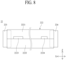
- FIGs. 8 to 10 two parallel curved lines are omission lines.
- a dotted line of FIG. 8 indicates a part of each of a first potting layer and a second potting layer located in an inner case.
- a humidifier 1 for fuel cells is configured to humidify dry gas supplied from the outside using wet gas discharged from a fuel cell stack (not shown).
- the dry gas may be fuel gas or air.
- the dry gas may be humidified by the wet gas and may then be supplied to the fuel cell stack.
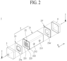
- the humidifier 1 for fuel cells according to the present disclosure includes a humidifying module 2 configured to humidify dry gas, a first cap 3 coupled to one end of the humidifying module 2, and a second cap 4 coupled to the other end of the humidifying module 2.
- the humidifying module 2 humidifies dry gas supplied from the outside.
- the first cap 3 may be coupled to one end of the humidifying module 2.
- the second cap 4 may be coupled to the other end of the humidifying module 2.
- the first cap 3 may transmit dry gas to the humidifying module 2.
- the second cap 4 may transmit dry gas humidified by wet gas in the humidifying module 2 to the fuel cell stack.
- the first cap 3 may transmit wet gas to the humidifying module 2.
- the second cap 4 may discharge wet gas to the outside after dry gas is humidified in the humidifying module 2.
- the first cap 3 and the second cap 4 may be spaced apart from each other in a first axis direction (X-axis direction).
- the humidifying module 2 includes a mid-case 21 and at least one cartridge 22.
- the cartridge 22 is coupled to the mid-case 21.
- the cartridge 22 may be disposed in the mid-case 21. Opposite ends of the mid-case 21 are open.
- a receiving hole 211 may be formed in the mid-case 21.
- the receiving hole 211 may be formed so as to extend through the mid-case 21 in the first axis direction (X-axis direction).
- An inlet 212 and an outlet 213 may be formed in the mid-case 21.
- the inlet 212 may allow wet gas or dry gas to be introduced into the mid-case 21 therethrough.
- the outlet 213 may allow wet gas or dry gas to be discharged from the mid-case 21 therethrough.
- the inlet 212 and the outlet 213 may be disposed spaced apart from each other in the first axis direction (X-axis direction).
- the wet gas When wet gas flows through the inlet 212 and the outlet 213, the wet gas may be supplied into the cartridge 22 via the interior of the mid-case 21 through the inlet 212, and may then come into contact with outer surfaces of hollow fiber membranes 221 of the cartridge 22. During this process, moisture contained in the wet gas may be transmitted through the hollow fiber membranes 221 to humidify dry gas flowing along hollows of the hollow fiber membranes 221.
- the humidified dry gas may be discharged from the hollow fiber membranes 221, and may then be supplied to the fuel cell stack through the second cap 4.
- the wet gas After humidifying the dry gas, the wet gas may be discharged from the cartridge 22, may flow along the interior of the mid-case 21, and may be discharged from the mid-case 21 through the outlet 213.
- the inlet 212 may be connected to the fuel cell stack such that wet gas is supplied thereto. Wet gas may be off-gas discharged from the fuel cell stack.
- the dry gas When dry gas flows through the inlet 212 and the outlet 213, the dry gas may be supplied into the cartridge 22 via the interior of the mid-case 21 through the inlet 212, and may then come into contact with the outer surfaces of the hollow fiber membranes 221. During this process, moisture in wet gas flowing along the hollows of the hollow fiber membranes 221 may be transmitted through the hollow fiber membranes 221 to humidify dry gas introduced into the cartridge 22.
- the humidified dry gas may be discharged from the cartridge 22, may flow along the interior of the mid-case 21, may be discharged from the mid-case 21 through the outlet 213, and may be supplied to the fuel cell stack.
- the wet gas After humidifying the dry gas, the wet gas may be discharged from the hollow fiber membranes 221, and may then be discharged to the outside through the second cap 4.
- the first cap 3 may be connected to the fuel cell stack such that wet gas is supplied thereto.
- the cartridge 22 is disposed in the mid-case 21, and includes a plurality of hollow fiber membranes 221.
- the hollow fiber membranes 221 may be coupled to the cartridge 22 so as to be modularized. Consequently, the hollow fiber membranes 221 may be installed in the mid-case 21 through a process of coupling the cartridge 22 to the mid-case 21.
- ease in installation, separation, and replacement of the hollow fiber membranes 221 may be improved.
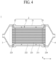
- the cartridge 22 may include an inner case 222.
- the inner case 222 has openings formed in ends thereof, and the plurality of hollow fiber membranes 221 is received in the inner case.
- the hollow fiber membranes 221 may be disposed in the inner case 222 so as to be modularized.
- the hollow fiber membranes 221 may include a polymer membrane made of polysulfone resin, polyethersulfone resin, sulfonated polysulfone resin, polyvinylidene fluoride (PVDF) resin, polyacrylonitrile (PAN) resin, polyimide resin, polyamide imide resin, polyester imide resin, or a mixture of two or more thereof.
- the cartridge 22 may include a first fixing layer 223.
- the first fixing layer 223 is configured to fix one end of each of the hollow fiber membranes 221.
- the first fixing layer 223 may close a corresponding one of the openings of the inner case 222.
- the first fixing layer 223 may be formed so as not to block the hollows of the hollow fiber membranes 221.
- the first fixing layer 223 may be formed by hardening a potting liquid, such as liquid polyurethane resin, through a casting process. A part of the first fixing layer 223 may be located in the inner case 222, and the remaining part of the first fixing layer may be protrude from the inner case 222.
- the first fixing layer 223 may fix one end of each of the hollow fiber membranes 221 to the inner case 222.
- the cartridge 22 may include a second fixing layer 224.
- the second fixing layer 224 is configured to fix the other end of each of the hollow fiber membranes 221.
- the second fixing layer 224 may close a corresponding one of the openings of the inner case 222.
- the second fixing layer 224 may be formed so as not to block the hollows of the hollow fiber membranes 221.
- the second fixing layer 224 may be formed by hardening a potting liquid, such as liquid polyurethane resin, through a casting process. A part of the second fixing layer 224 may be located in the inner case 222, and the remaining part of the second fixing layer may protrude from the inner case 222.
- the second fixing layer 224 may fix the other end of each of the hollow fiber membranes 221 to the inner case 222.
- the second fixing layer 224 and the first fixing layer 223 may be formed so as not to block the hollows of the hollow fiber membranes 221, dry gas or wet gas supplied from the outside may be supplied to the hollows of the hollow fiber membranes 221 without being disturbed by the second fixing layer 224 and the first fixing layer 223, and may be discharged from the hollows of the hollow fiber membranes 221 without being disturbed by the second fixing layer 224 and the first fixing layer 223.
- the second fixing layer 224 and the first fixing layer 223 may be disposed spaced apart from each other in the first axis direction (X-axis direction).
- the humidifying module 2 may include a plurality of packing members 23 and 23'.
- the packing members 23 and 23' form a hermetic seal between the cartridge 22 and the mid-case 21 in order to prevent direct mixing between dry gas and wet gas.
- the packing members 23 and 23' may be inserted between the cartridge 22 and the mid-case 21.
- the cartridge 22 may be inserted through through-holes 23a and 23a' formed respectively in the packing members 23 and 23'.
- the packing members 23 and 23' may be disposed respectively at opposite sides of the cartridge 22.
- resin layers may be formed respectively at the opposite sides of the cartridge 22 instead of the packing members 23 and 23'. Each of the resin layers may be formed by hardening a liquid polymer, such as liquid polyurethane resin, using a casting method.
- the first cap 3 is coupled to one end of the humidifying module 2.
- a space between the first cap 3 and the cartridge 22 may be isolated from a space between the cartridge 22 and the mid-case 21 in a hermetically sealed state by the packing member 23 or the resin layer.
- the second cap 4 is coupled to the other end of the humidifying module 2.
- the second cap 4 may be coupled to the other end of the humidifying module 2 so as to be spaced apart from the first cap 3 in the first axis direction (X-axis direction).
- a space between the second cap 4 and the cartridge 22 may be isolated from the space between the cartridge 22 and the mid-case 21 in a hermetically sealed state by the packing member 23' or the resin layer.
- the inner case 222 may be implemented through assembly of two or more divided cases.
- the humidifier 1 for fuel cells according to the present disclosure therefore, it is possible to individually manufacture the divided cases by injection molding, whereby it is possible to improve ease in manufacture, compared to when the inner case 222 is manufactured by performing injection molding once.
- the divided cases may be assembled using a sliding method.
- a potting liquid may flow out through the interface between the divided cases during a process of forming the first fixing layer 223 and the second fixing layer 224.
- the inner case 222 may be implemented as follows.
- the inner case 222 may include a first divided case 2221, a second divided case 2222, and a first press-fit member 2223.
- the first divided case 2221 and the second divided case 2222 are configured to receive the hollow fiber membranes 221.
- Each of the first divided case 2221 and the second divided case 2222 may correspond to a divided case configured to implement the inner case 222 through assembly.
- a description will be given based on an embodiment in which the inner case 222 is implemented through assembly between the first divided case 2221 and the second divided case 2222; however, it is obvious to those skilled in the art to which the present disclosure pertains that an embodiment in which the inner case 222 is implemented through assembly of three or more divided cases can be derived therefrom.
- the first divided case 2221 may be disposed so as to cover an upper side of the hollow fiber membranes 221.
- the second divided case 2222 may be disposed so as to cover a lower side of the hollow fiber membranes 221.
- the first divided case 2221 and the second divided case 2222 may cover opposite side surfaces of the hollow fiber membranes 221, respectively.
- the opposite side surfaces of the hollow fiber membranes 221 are based on a second axis direction (Y-axis direction), which is perpendicular to the first axis direction (X-axis direction).
- the interface between the first divided case 2221 and the second divided case 2222 may be disposed at the opposite side surfaces of the hollow fiber membranes 221.
- the first divided case 2221 may be disposed so as to cover the lower side of the hollow fiber membranes 221
- the second divided case 2222 may be disposed so as to cover the upper side of the hollow fiber membranes 221.
- the first press-fit member 2223 is configured to couple the first divided case 2221 and the second divided case 2222 to each other by press-fit.
- the first divided case 2221 and the second divided case 2222 may be coupled to each other using the first press-fit member 2223, whereby it is possible to reduce the outflow amount of the potting liquid through the interface between the first divided case 2221 and the second divided case 2222.
- the humidifier 1 for fuel cells it is possible to reduce the amount of the potting liquid that is introduced into the inner case 222 from the outside of the inner case 222 through the interface between the first divided case 2221 and the second divided case 2222 using the first press-fit member 2223.
- the first press-fit member 2223 may be interference-fit as the result of press-fit, whereby it is possible to prevent the interface between the first divided case 2221 and the second divided case 2222 from being opened, thereby preventing a gap from being generated therebetween.
- the first press-fit member 2223 may be disposed such that the distance from the first fixing layer 223 is shorter than the distance from the second fixing layer 224. That is, the first press-fit member 2223 may be disposed closer to the first fixing layer 223.
- the first press-fit member 2223 may include a first sliding groove 2223a (shown in FIG. 6 ) and a first insertion member 2223b.
- the first sliding groove 2223a is formed in the first divided case 2221.
- the first divided case 2221 and the second divided case 2222 may be assembled by sliding through the first sliding groove 2223a.
- at least one of the first divided case 2221 and the second divided case 2222 may be moved in a direction toward each other, whereby the first divided case and the second divided case may be assembly by sliding.
- the first sliding groove 2223a may be formed so as to extend in parallel to the first axis direction (X-axis direction).
- the first insertion member 2223b is formed on the second divided case 2222. During a process in which the first divided case 2221 and the second divided case 2222 are assembled by sliding, the first insertion member 2223b may be inserted into the first sliding groove 2223a. At least a part of the first insertion member 2223b may be formed so as to have a larger size than the first sliding groove 2223a. As a result, the first insertion member 2223b may be press-fit while being inserted into the first sliding groove 2223a. In the humidifier 1 for fuel cells according to the present disclosure, therefore, it is possible to increase the force of coupling between the first divided case 2221 and the second divided case 2222 through press-fit of the first insertion member 2223b.
- At least a part of the first insertion member 2223b being formed so as to have a larger size than the first sliding groove 2223a may be based on the sectional area thereof taken in the second axis direction (Y-axis direction).
- the entirety of the first insertion member 2223b may be formed so as to have a larger size than the first sliding groove 2223a.
- the first insertion member 2223b may protrude from the second divided case 2222.
- the first insertion member 2223b may protrude from the opposite surface of the second divided case 2222 that faces the first divided case 2221 toward the first divided case 2221.
- the first insertion member 2223b may be disposed so as to overlap the first divided case 2221.
- the first insertion member 2223b and the second divided case 2222 may be integrally formed.
- the first press-fit member 2223 may include a first protruding member 2223c and a first catching member 2223d.
- the first protruding member 2223c is formed on the first divided case 2221.
- the first protruding member 2223c may protrude from an outer surface 2221a of the first divided case 2221 in an outward direction (direction indicated by arrow OD).
- the outer surface 2221a of the first divided case 2221 is a surface of the first divided case 2221 based on the second axis direction (Y-axis direction).
- the outward direction (direction indicated by arrow OD) may mean an outside direction of the first divided case 2221 based on an inner space thereof in which the hollow fiber membranes 221 are received.
- the outward direction (direction indicated by arrow OD) may be parallel to the second axis direction (Y-axis direction).
- the first protruding member 2223c and the first divided case 2221 may be integrally formed.
- the first sliding groove 2223a may be formed in the first protruding member 2223c.
- a part of the first sliding groove 2223a may be formed through the first protruding member 2223c.
- a part of the first insertion member 2223b may be inserted into the part of the first sliding groove 2223a formed through the first protruding member 2223c.
- the first catching member 2223d may protrude from the first insertion member 2223b in the outward direction (direction indicated by arrow OD). As a result, the first catching member 2223d may be inserted into the first sliding groove 2223a and may be supported by the first protruding member 2223c. In the humidifier 1 for fuel cells according to the present disclosure, therefore, it is possible to further increase the force by which the interface between the first divided case 2221 and the second divided case 2222 is prevented from being opened, whereby a gap is prevented from being generated therebetween, using supporting force of the first protruding member 2223c that supports the first catching member 2223d.
- the first catching member 2223d and the first insertion member 2223b may generally be formed in a hook shape.
- the first catching member 2223d and the first insertion member 2223b may be integrally formed.
- the first press-fit member 2223 may include a first restriction member 2223e.
- the first restriction member 2223e protrudes from the first protruding member 2223c.
- the first restriction member 2223e may protrude from the first protruding member 2223c in an upward-downward direction (Z-axis direction).
- the upward-downward direction (Z-axis direction) is a direction perpendicular to each of the first axis direction (X-axis direction) and the second axis direction (Y-axis direction).
- the first restriction member 2223e may protrude from the first protruding member 2223c in a direction from the second divided case 2222 to the first divided case 2221.
- the first restriction member 2223e and the first protruding member 2223c may be integrally formed.
- the first restriction member 2223e and the outer surface 2221a of the first divided case 2221 may be disposed so as to face each other in the state in which the first sliding groove 2223a is located therebetween.
- the first sliding groove 2223a may be disposed between the first restriction member 2223e and the first divided case 2221. Consequently, a part of the first insertion member 2223b and the first catching member 2223d may be inserted into the first sliding groove 2223a, whereby the first insertion member 2223b and the first catching member 2223d may be press-fit between the first restriction member 2223e and the outer surface of the first divided case 2221.
- the humidifier 1 for fuel cells therefore, it is possible to further increase the force of press-fitting the first insertion member 2223b and the first catching member 2223d using the first restriction member 2223e.
- the distance between the first restriction member 2223e and the outer surface 2221a of the first divided case 2221 may be implemented so as to be less than the sum of the length of the first insertion member 2223b and the length of the first catching member 2223d.
- the first insertion member 2223b and the first catching member 2223d may be press-fit by the first restriction member 2223e and the outer surface 2221a of the first divided case 2221 while being inserted into the first sliding groove 2223a.
- a guide groove 2221b shown in FIG.
- the guide groove 2221b may correspond to a part of the first sliding groove 2223a.
- the first press-fit member 2223 described above may be disposed at each of opposite sides of the inner case 222 based on the second axis direction (Y-axis direction). Consequently, the humidifier 1 for fuel cells according to the present disclosure may be implemented so as to reduce the outflow amount and the inflow amount of the potting liquid through the interface between the first divided case 2221 and the second divided case 2222 at each of the opposite sides of the inner case 222 using the first press-fit member 2223.
- the inner case 222 may include a second press-fit member 2224 (shown in FIG. 8 ) .
- the second press-fit member 2224 is configured to couple the first divided case 2221 and the second divided case 2222 to each other by press-fit.
- the second press-fit member 2224 may be spaced apart from the first press-fit member 2223 in the first axis direction (X-axis direction).
- the second press-fit member 2224 and the first press-fit member 2223 may couple the first divided case 2221 and the second divided case 2222 to each other by press-fit at different positions.
- the humidifier 1 for fuel cells according to the present disclosure therefore, it is possible to more securely couple the first divided case 2221 and the second divided case 2222 to each other, whereby it is possible to further reduce the outflow amount and the inflow amount of the potting liquid through the interface between the first divided case 2221 and the second divided case 2222.
- the second press-fit member 2224 may be disposed such that the distance from the second fixing layer 224 is shorter than the distance from the first fixing layer 223. That is, the second press-fit member 2224 may be disposed closer to the second fixing layer 224.
- the second press-fit member 2224 may be disposed at each of the opposite sides of the inner case 222 based on the second axis direction (Y-axis direction). Consequently, the humidifier 1 for fuel cells according to the present disclosure may be implemented so as to reduce the outflow amount and the inflow amount of the potting liquid through the interface between the first divided case 2221 and the second divided case 2222 at each of the opposite sides of the inner case 222 using the second press-fit member 2224.
- the second press-fit member 2224 may include a second sliding groove, a second insertion member, a second protruding member, a second catching member, and a second restriction member.
- the second sliding groove, the second insertion member, the second protruding member, the second catching member, and the second restriction member may be implemented so as to approximately coincide with the first sliding groove 2223a, the first insertion member 2223b, the first protruding member 2223c, the first catching member 2223d, and the first restriction member 2223e, respectively, and therefore a detailed description thereof will be omitted.
- the second press-fit member 2224 and the first press-fit member 2223 may be formed so as to be different from each other in terms of at least one of shape and size. Consequently, the humidifier 1 for fuel cells according to the present disclosure is implemented so as to be capable of checking an assembly direction of the first divided case 2221 and the second divided case 2222 with the naked eye using the second press-fit member 2224 and the first press-fit member 2223.
- the shape of each of the second press-fit member 2224 and the first press-fit member 2223 may mean the contour of each of spaces occupied by the second press-fit member 2224 and the first press-fit member 2223.
- the first press-fit member 2223 may be formed in the shape of a disk.
- the size of each of the second press-fit member 2224 and the first press-fit member 2223 may be set based on the length of each of the second press-fit member 2224 and the first press-fit member 2223 based on at least one of the first axis direction (X-axis direction), the second axis direction (Y-axis direction), and the upward-downward direction (Z-axis direction).
- the first press-fit member 2223 may be formed so as to have a larger length than the second press-fit member 2224 based on the first axis direction (X-axis direction), whereby the first press-fit member may be formed so as to have a different length from the second press-fit member 2224.
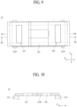
- the cartridge 22 may include a gas inlet 225 and a gas outlet 226.
- the gas inlet 225 is formed in the inner case 222.
- the gas inlet 225 may be formed at one side 2220 of the inner case 222. Based on FIG. 10 , one side 2220 of the inner case 222 may correspond to an upper surface.
- the gas inlet 225 may allow wet gas or dry gas to be introduced into the inner case 222 therethrough.
- the gas inlet 225 may be formed through the inner case 222. As shown in FIGs. 9 and 10 , the gas inlet 225 may be implemented by one through-hole formed through the inner case 222. As shown in FIG. 5 , the gas inlet 225 may be implemented by a plurality of through-holes formed through the inner case 222.
- the gas inlet 225 may include a plurality of inflow windows 225a formed through different parts of the inner case 222.
- the inflow windows 225a may be disposed spaced apart from each other in the first axis direction (X-axis direction) and the second axis direction (Y-axis direction) so as to form a matrix.
- the gas inlet 225 and the first fixing layer 223 may be spaced apart from each other in the first axis direction (X-axis direction).
- the gas inlet 225 and the first fixing layer 223 do not overlap each other. Consequently, it is possible to prevent the first fixing layer 223 from being damaged or broken by the pressure of wet gas or dry gas introduced through the gas inlet 225.
- a dotted line indicates the position of one surface of the first fixing layer 223 that faces the gas inlet 225.
- the gas outlet 226 is formed in the inner case 222.
- the gas outlet 226 may be formed at one side 2220 of the inner case 222.
- the gas outlet 226 may allow wet gas or dry gas to be discharged from the inner case 222 therethrough.
- the gas outlet 226 may be formed through the inner case 222.
- the gas outlet 226 may be implemented by one through-hole formed through the inner case 222.
- the gas outlet 226 may be implemented by a plurality of through-holes formed through the inner case 222.
- the gas outlet 226 may include a plurality of outflow windows 226a formed through different parts of the inner case 222.
- the outflow windows 226a may be disposed spaced apart from each other in the first axis direction (X-axis direction) and the second axis direction (Y-axis direction) so as to form a matrix.
- the gas outlet 226 and the second fixing layer 224 may be spaced apart from each other in the first axis direction (X-axis direction).
- the gas outlet 226 and the second fixing layer 224 do not overlap each other. Consequently, it is possible to prevent the second fixing layer 224 from being damaged or broken by the pressure of wet gas or dry gas discharged through the gas outlet 226.
- a dotted line indicates the position of one surface of the second fixing layer 224 that faces the gas outlet 226.
- the gas outlet 226 and the gas inlet 225 may be located between the second fixing layer 224 and the first fixing layer 223 based on the first axis direction (X-axis direction).
- the gas outlet 226 and the gas inlet 225 may be disposed spaced apart from each other in the first axis direction (X-axis direction).
- the wet gas When wet gas flows through the gas outlet 226 and the gas inlet 225, the wet gas may be supplied to a space between an inner surface of the mid-case 21 and an outer surface of the inner case 222 through the inlet 212, may be supplied into the inner case 222 through the gas inlet 225, and may come into contact with the outer surfaces of the hollow fiber membranes 221.
- moisture contained in the wet gas may be transmitted through the hollow fiber membranes 221 to humidify dry gas flowing along the hollows of the hollow fiber membranes 221.
- the humidified dry gas may be discharged from the hollow fiber membranes 221, and may then be supplied to the fuel cell stack through the second cap 4.
- the wet gas After humidifying the dry gas, the wet gas may be discharged to the space between the outer surface of the inner case 222 and the inner surface of the mid-case 21 through the gas outlet 226, and may be discharged from the mid-case 21 through the outlet 213.
- the dry gas When dry gas flows through the gas outlet 226 and the gas inlet 225, the dry gas may be supplied to the space between the inner surface of the mid-case 21 and the outer surface of the inner case 222 through the inlet 212, may be supplied into the inner case 222 through the gas inlet 225, and may come into contact with the outer surface of the hollow fiber membrane bundle 22. During this process, moisture in wet gas flowing along the hollows of the hollow fiber membranes 221 may be transmitted through the hollow fiber membranes 221 to humidify the dry gas introduced into the inner case 222.
- the humidified dry gas may be discharged to the space between the outer surface of the inner case 222 and the inner surface of the mid-case 21 through the gas outlet 226, may be discharged from the mid-case 21 through the outlet 213, and may be supplied to the fuel cell stack.
- the wet gas may be discharged from the hollow fiber membranes 221, and may then be discharged to the outside through the second cap 4.
Landscapes
- Chemical & Material Sciences (AREA)
- Chemical Kinetics & Catalysis (AREA)
- Engineering & Computer Science (AREA)
- Manufacturing & Machinery (AREA)
- Life Sciences & Earth Sciences (AREA)
- Sustainable Development (AREA)
- Sustainable Energy (AREA)
- Electrochemistry (AREA)
- General Chemical & Material Sciences (AREA)
- Fuel Cell (AREA)
Applications Claiming Priority (2)
| Application Number | Priority Date | Filing Date | Title |
|---|---|---|---|
| KR20200187672 | 2020-12-30 | ||
| PCT/KR2021/016393 WO2022145702A1 (ko) | 2020-12-30 | 2021-11-11 | 연료전지용 가습기의 카트리지 및 연료전지용 가습기 |
Publications (2)
| Publication Number | Publication Date |
|---|---|
| EP4239737A1 true EP4239737A1 (de) | 2023-09-06 |
| EP4239737A4 EP4239737A4 (de) | 2024-09-18 |
Family
ID=82260878
Family Applications (1)
| Application Number | Title | Priority Date | Filing Date |
|---|---|---|---|
| EP21915500.9A Pending EP4239737A4 (de) | 2020-12-30 | 2021-11-11 | Kartusche eines brennstoffzellenbefeuchters und brennstoffzellenbefeuchter |
Country Status (6)
| Country | Link |
|---|---|
| US (1) | US20240021848A1 (de) |
| EP (1) | EP4239737A4 (de) |
| KR (1) | KR102744568B1 (de) |
| CN (1) | CN116801964A (de) |
| CA (1) | CA3202664A1 (de) |
| WO (1) | WO2022145702A1 (de) |
Families Citing this family (2)
| Publication number | Priority date | Publication date | Assignee | Title |
|---|---|---|---|---|
| KR20250020213A (ko) * | 2023-08-03 | 2025-02-11 | 코오롱인더스트리 주식회사 | 연료전지용 가습기의 카트리지 및 연료전지용 가습기 |
| KR20260031541A (ko) * | 2024-08-29 | 2026-03-09 | 코오롱인더스트리 주식회사 | 원통형 카트리지 및 원통형 카트리지를 포함하는 연료전지용 가습기 |
Family Cites Families (14)
| Publication number | Priority date | Publication date | Assignee | Title |
|---|---|---|---|---|
| FR2231421B1 (de) * | 1973-05-30 | 1976-05-07 | Rhone Poulenc Ind | |
| DE3611623A1 (de) * | 1985-04-27 | 1986-10-30 | Akzo Patente GmbH, 42103 Wuppertal | Stoff- und/oder waermeaustauscher |
| SE515122C2 (sv) * | 1999-01-29 | 2001-06-11 | Gambro Lundia Ab | Filter och metod för tillverkning av filter för dialys |
| US7938386B2 (en) * | 2006-03-13 | 2011-05-10 | GM Global Technology Operations LLC | Fuel cell air humidifier |
| KR100796656B1 (ko) * | 2006-07-05 | 2008-01-22 | 삼성에스디아이 주식회사 | 연료 전지 시스템 |
| CN104246379A (zh) * | 2012-03-13 | 2014-12-24 | 日产自动车株式会社 | 加湿器 |
| EP2735358B1 (de) * | 2012-11-22 | 2018-01-10 | Gambro Lundia AB | Hohlfaserdialysatoren |
| KR101655619B1 (ko) * | 2014-12-17 | 2016-09-07 | 현대자동차주식회사 | 연료전지의 막 가습기 및 이를 이용한 공기흐름 시스템 |
| JP6628352B2 (ja) * | 2015-08-17 | 2020-01-08 | 旭化成株式会社 | 中空糸膜モジュール |
| KR102186187B1 (ko) * | 2016-12-29 | 2020-12-03 | 코오롱인더스트리 주식회사 | 중공사막 모듈 제조방법 및 이에 의해 제조된 중공사막 모듈 |
| KR102700490B1 (ko) * | 2018-11-15 | 2024-08-30 | 주식회사 엘지에너지솔루션 | 후크 결합구조 및 이를 사용한 배터리 팩 케이스 |
| EP4445994A3 (de) * | 2018-12-28 | 2024-12-18 | Kolon Industries, Inc. | Membranbefeuchter für brennstoffzelle |
| KR20200122211A (ko) * | 2019-04-17 | 2020-10-27 | 코오롱인더스트리 주식회사 | 연료전지용 가습기 및 그것을 위한 패킹 부재 |
| KR102430374B1 (ko) * | 2019-04-17 | 2022-08-08 | 코오롱인더스트리 주식회사 | 연료전지용 가습기 및 그것을 위한 패킹 부재 |
-
2021
- 2021-11-11 EP EP21915500.9A patent/EP4239737A4/de active Pending
- 2021-11-11 WO PCT/KR2021/016393 patent/WO2022145702A1/ko not_active Ceased
- 2021-11-11 US US18/253,418 patent/US20240021848A1/en active Pending
- 2021-11-11 CN CN202180088938.1A patent/CN116801964A/zh active Pending
- 2021-11-11 KR KR1020210154461A patent/KR102744568B1/ko active Active
- 2021-11-11 CA CA3202664A patent/CA3202664A1/en active Pending
Also Published As
| Publication number | Publication date |
|---|---|
| CA3202664A1 (en) | 2022-07-07 |
| CN116801964A (zh) | 2023-09-22 |
| WO2022145702A1 (ko) | 2022-07-07 |
| KR20220097208A (ko) | 2022-07-07 |
| US20240021848A1 (en) | 2024-01-18 |
| KR102744568B1 (ko) | 2024-12-19 |
| EP4239737A4 (de) | 2024-09-18 |
Similar Documents
| Publication | Publication Date | Title |
|---|---|---|
| US20220344684A1 (en) | Cartridge of fuel cell humidifier and fuel cell humidifier | |
| US12145106B2 (en) | Humidifier for fuel cell | |
| EP4235879A1 (de) | Befeuchtersystem für eine brennstoffzelle | |
| EP4273975B1 (de) | Befeuchter für eine brennstoffzelle | |
| EP4293765A1 (de) | Kartusche für brennstoffzellenbefeuchter und brennstoffzellenbefeuchter | |
| US20230402627A1 (en) | Cartridge of humidifier for fuel cell and humidifier for fuel cell | |
| CA3157147C (en) | Fuel cell humidifier | |
| EP4239737A1 (de) | Kartusche eines brennstoffzellenbefeuchters und brennstoffzellenbefeuchter | |
| KR102728782B1 (ko) | 연료전지용 가습시스템 | |
| US12548788B2 (en) | Cartridge of humidifier for fuel cell and humidifier for fuel cell | |
| US20250357508A1 (en) | Mid-case of humidifier for fuel cell and humidifier for fuel cell | |
| US12327893B2 (en) | Humidifier for fuel cell | |
| CA3196328C (en) | Cartridge of humidifier for fuel cell and humidifier for fuel cell | |
| EP4629354A1 (de) | Kartusche für brennstoffzellenbefeuchter und brennstoffzellenbefeuchter | |
| EP4258395B1 (de) | Befeuchter für eine brennstoffzelle | |
| EP4521498A1 (de) | Verpackungseinheit für einen brennstoffzellenbefeuchter und brennstoffzellenbefeuchter | |
| CA3202611C (en) | Humidifier for fuel cell | |
| EP4513601A1 (de) | Mittelgehäuse eines befeuchters für eine brennstoffzelle und befeuchter für eine brennstoffzelle | |
| CA3256309A1 (en) | Mid-case of humidifier for fuel cell, and humidifier for fuel cell | |
| CA3257071A1 (en) | Packing unit for fuel cell humidifier, and fuel cell humidifier |
Legal Events
| Date | Code | Title | Description |
|---|---|---|---|
| STAA | Information on the status of an ep patent application or granted ep patent |
Free format text: STATUS: THE INTERNATIONAL PUBLICATION HAS BEEN MADE |
|
| PUAI | Public reference made under article 153(3) epc to a published international application that has entered the european phase |
Free format text: ORIGINAL CODE: 0009012 |
|
| STAA | Information on the status of an ep patent application or granted ep patent |
Free format text: STATUS: REQUEST FOR EXAMINATION WAS MADE |
|
| 17P | Request for examination filed |
Effective date: 20230531 |
|
| AK | Designated contracting states |
Kind code of ref document: A1 Designated state(s): AL AT BE BG CH CY CZ DE DK EE ES FI FR GB GR HR HU IE IS IT LI LT LU LV MC MK MT NL NO PL PT RO RS SE SI SK SM TR |
|
| DAV | Request for validation of the european patent (deleted) | ||
| DAX | Request for extension of the european patent (deleted) | ||
| A4 | Supplementary search report drawn up and despatched |
Effective date: 20240819 |
|
| RIC1 | Information provided on ipc code assigned before grant |
Ipc: B01D 63/02 20060101ALI20240812BHEP Ipc: H01M 8/04119 20160101AFI20240812BHEP |
|
| STAA | Information on the status of an ep patent application or granted ep patent |
Free format text: STATUS: EXAMINATION IS IN PROGRESS |
|
| 17Q | First examination report despatched |
Effective date: 20250512 |