EP4239445A2 - Electronic device assembly, expansion component thereof, and heat dissipation module - Google Patents
Electronic device assembly, expansion component thereof, and heat dissipation module Download PDFInfo
- Publication number
- EP4239445A2 EP4239445A2 EP23155305.8A EP23155305A EP4239445A2 EP 4239445 A2 EP4239445 A2 EP 4239445A2 EP 23155305 A EP23155305 A EP 23155305A EP 4239445 A2 EP4239445 A2 EP 4239445A2
- Authority
- EP
- European Patent Office
- Prior art keywords
- section
- heat dissipation
- case
- height
- expansion component
- Prior art date
- Legal status (The legal status is an assumption and is not a legal conclusion. Google has not performed a legal analysis and makes no representation as to the accuracy of the status listed.)
- Pending
Links
Images




Classifications
-
- H—ELECTRICITY
- H05—ELECTRIC TECHNIQUES NOT OTHERWISE PROVIDED FOR
- H05K—PRINTED CIRCUITS; CASINGS OR CONSTRUCTIONAL DETAILS OF ELECTRIC APPARATUS; MANUFACTURE OF ASSEMBLAGES OF ELECTRICAL COMPONENTS
- H05K7/00—Constructional details common to different types of electric apparatus
- H05K7/20—Modifications to facilitate cooling, ventilating, or heating
- H05K7/20009—Modifications to facilitate cooling, ventilating, or heating using a gaseous coolant in electronic enclosures
- H05K7/20136—Forced ventilation, e.g. by fans
- H05K7/20154—Heat dissipaters coupled to components
-
- G—PHYSICS
- G06—COMPUTING OR CALCULATING; COUNTING
- G06F—ELECTRIC DIGITAL DATA PROCESSING
- G06F1/00—Details not covered by groups G06F3/00 - G06F13/00 and G06F21/00
- G06F1/16—Constructional details or arrangements
- G06F1/1613—Constructional details or arrangements for portable computers
- G06F1/1632—External expansion units, e.g. docking stations
-
- G—PHYSICS
- G06—COMPUTING OR CALCULATING; COUNTING
- G06F—ELECTRIC DIGITAL DATA PROCESSING
- G06F1/00—Details not covered by groups G06F3/00 - G06F13/00 and G06F21/00
- G06F1/16—Constructional details or arrangements
- G06F1/20—Cooling means
- G06F1/203—Cooling means for portable computers, e.g. for laptops
Definitions
- the present invention relates to an electronic device assembly, an expansion component thereof, and a heat dissipation module.
- the present invention provides an expansion component, including a case, a partition, a plurality of electronic components, and a heat dissipation module.
- the case includes a bottom plate, a top plate, and an accommodating space located between the bottom plate and the top plate.
- the partition is arranged in the accommodating space and parallel to the bottom plate, and the partition divides the accommodating space into an upper compartment and a lower compartment.
- the electronic components are scattered in the upper compartment and the lower compartment, where one of the electronic components located in the upper compartment abuts against the partition.
- the heat dissipation module is arranged in the case and includes a diversion case and a fan.
- the diversion case includes an input section and an output section that are connected, an angle is defined between an extending direction of the input section and an extending direction of the output section, the diversion case is accommodated in the lower compartment, and the output section abuts against the partition and one of the electronic components located in the lower compartment.
- the fan is arranged at a junction of the input section and the output section.
- the bottom plate includes through holes
- the diversion case includes an edge, the edge surrounds and forms an opening, the edge abuts against the bottom plate, and the opening covers the through holes.
- the through holes include first through holes and second through holes, the first through holes correspond to a position of the input section, and the second through holes correspond to a position of the output section.
- the diversion case includes an inner surface, the inner surface faces toward the bottom plate, the output section includes a first heat dissipation section and a second heat dissipation section, the inner surface has a first height between the first heat dissipation section and the opening, the inner surface has a second height between the second heat dissipation section and the opening, and the first height is different from the second height.
- the expansion component further includes heat dissipation fins that are arranged on the first heat dissipation section and the second heat dissipation section.
- the first heat dissipation section abuts against the electronic component located in the lower compartment
- the second heat dissipation section abuts against a position at which the partition corresponds to the electronic component located in the upper compartment.
- the first heat dissipation section is farther away from the fan than the second heat dissipation section, and the first height is less than the second height.
- the inner surface is inclined to the bottom plate in an extending direction between the first heat dissipation section and the second heat dissipation section.
- the output section further includes a third heat dissipation section, the inner surface has a third height between the third heat dissipation section and the opening, and the third height is different from the first height and the second height.
- the third heat dissipation section is closer to the fan than the first heat dissipation section and the second heat dissipation section, and the third heat dissipation section abuts against another electronic component located in the lower compartment.
- the third heat dissipation section is flush with the fan, and the third height is greater than the first height and less than the second height.
- the input section of the diversion case includes an inlet section, the inlet section has a first end and a second end, the inner surface is inclined to the bottom plate at the inlet section, the second end is closer to the fan than the first end, and a height of the inner surface from the second end to the opening is greater than a height of the inner surface from the first end to the opening.
- the expansion component further includes heat dissipation fins that are arranged on the inlet section.
- the input section of the diversion case further includes a collecting section, the collecting section is located between the inlet section and the fan, the inner surface has the second height from the collecting section to the opening, and the collecting section abuts against the partition.
- the fan includes a case, the case is provided with an air inlet and an air outlet that are perpendicular to each other, the air inlet faces toward the inner surface and is spaced apart from the inner surface by a distance, and the air outlet faces toward the output section.
- the inner surface has the second height from the fan to the opening.
- the angle is 90 degrees.
- the present invention provides another expansion component, including a case, a partition, a plurality of electronic components, and a heat dissipation module.
- the case includes a bottom plate, a top plate, and an accommodating space located between the bottom plate and the top plate.
- the partition is arranged in the accommodating space and parallel to the bottom plate, and the partition divides the accommodating space into an upper compartment and a lower compartment.
- the electronic components are scattered in the upper compartment and the lower compartment, where one of the electronic components located in the upper compartment abuts against the partition.
- the heat dissipation module is arranged in the case and includes a diversion case and a fan.
- the diversion case includes an input section and an output section that are connected to form an L-shape, where the diversion case is accommodated in the lower compartment and fixed to the bottom plate, and the output section abuts against the partition and one of the electronic components located in the lower compartment.
- the fan is arranged at a junction of the input section and the output section.
- the present invention further provides an electronic device assembly, including an expansion component and a host.
- the expansion component includes a first case, a partition, a plurality of electronic components, a heat dissipation module, and a first connector.
- the host includes a second case, a main circuit board, and a main connector.
- the first case includes a bottom plate, a top plate, and a first accommodating space located between the bottom plate and the top plate, where the top plate is provided with an opening.
- the partition is arranged in the first accommodating space and parallel to the bottom plate, and the partition divides the first accommodating space into an upper compartment and a lower compartment.
- the electronic components are scattered in the upper compartment and the lower compartment, where one of the electronic components located in the upper compartment abuts against the partition.
- the heat dissipation module is arranged in the case and includes a diversion case and a fan.
- the diversion case includes an input section and an output section that are connected to form an L-shape, where the diversion case is accommodated in the lower compartment and fixed to the bottom plate, and the output section abuts against the partition and one of the electronic components located in the lower compartment.
- the fan is arranged at a junction of the input section and the output section.
- the first connector is electrically connected to a first circuit board and exposed from the top plate at the opening.
- the second case has a second accommodating space. The main circuit board is accommodated in the second accommodating space.
- the main connector is electrically connected to the main circuit board and the main connector is arranged on a surface of the second case, where after the host is assembled to the expansion component, the second case covers the top plate of the first case and the opening, and the first connector is electrically connected to the main connector.
- the present invention further provides a heat dissipation module, including a diversion case and a fan.
- the diversion case includes an input section, an output section, and a connecting section that connects the input section and the output section, where an angle is defined between an extending direction of the input section and an extending direction of the output section, and an end of the input section away from the connecting section and an end of the output section away from the connecting section are respectively inclined relative to the connecting section.
- the fan is accommodated in the connecting section.
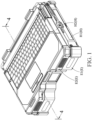
- FIG. 1 is a schematic three-dimensional external view of an embodiment of an electronic device assembly according to the present invention
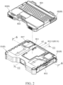
- FIG. 2 is a first schematic three-dimensional exploded diagram of an embodiment of an electronic device assembly according to the present invention
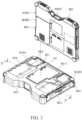
- FIG. 3 is a second schematic three-dimensional exploded diagram of an embodiment of an electronic device assembly according to the present invention
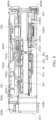
- FIG. 4 is a schematic cross-sectional view drawn along a division line 4-4 in FIG. 1 .
- the present invention provides an electronic device assembly, including a plurality of overlapping electronic devices E.
- the electronic devices E include cases H and electronic components A respectively, each of the cases H has an accommodating space S, the electronic components A are assembled in the accommodating space 5 of each of the cases H, and the electronic components A in adjacent cases H are assembled in an overlapping manner in the two cases H and can be electrically connected to each other. Therefore, the electronic device assembly may use the accommodating spaces S of the plurality of electronic devices E without external wiring to increase a quantity and types of assembled electronic components A, thereby satisfying diversified electronic function expansion.
- the cases H and different electronic components A arranged inside the cases may be matched and combined into electronic devices E with different function orientations.
- the electronic components A may be circuit boards, connectors, storage elements, or power supply elements with different function orientations.
- the electronic device assembly includes two electronic devices E, where each of the electronic devices E includes a case H.
- each of the electronic devices E includes a case H.
- An example in which the two electronic devices E are respectively an expansion component E1 and a host E2 is used below for description, but the present invention is not limited thereto.
- the cases H include a first case H1 and a second case H2, where the first case H1 includes a first accommodating space S1, the second case H2 includes a second accommodating space S2, the first case H1 is a part of the expansion component E1, and the second case H2 is a part of the host E2.
- the electronic device assembly includes the expansion component E1 and the host E2.
- the expansion component E1 includes the first accommodating space S1
- the host E2 includes the second accommodating space S2
- different electronic components A are respectively arranged in the first accommodating space S1 and the second accommodating space S2.
- one surface of the expansion component E1 abuts against and is electrically connected to one surface of the host E2, to increase spaces of the electronic device assembly for assembling the electronic components A and functions that can be provided by the electronic device assembly.
- the electronic components A include a first circuit board A1 and a first connector A2 arranged in the first accommodating space S1 of the expansion component E1 and a main circuit board A3 and a main connector A4 arranged in the second accommodating space S2 of the host E2.
- the main circuit board A3 may be a main board
- the first circuit board A1 is various expansion circuit boards that can cooperate with the main board, but the present invention is not limited thereto.
- the expansion component E1 includes the first case H1, the first circuit board A1, and at least one first connector A2.
- the first case H1 includes a top plate H11 and a bottom plate H12 that are opposite to each other, where the first accommodating space S1 is formed between the top plate H11 and the bottom plate H12, and the top plate H11 is provided with an opening H111.
- the first circuit board A1 is arranged in the first accommodating space S1.
- the first connector A2 is electrically connected to the first circuit board A1, and the first connector A2 is exposed from the top plate H11 at the opening H111. It should be noted that as shown in FIG.
- the opening H111 is further equipped with a plate that corresponds to a contour shape of the opening H111, and a through hole for the first connector A2 to pass through is provided on the plate, to prevent external water vapor or dust from entering the first case H1 at the opening H111.
- the opening H111 may not be provided with the plate, so that different electronic components A in the first case H1 pass through the opening H111.
- the present invention is not limited thereto.
- the host E2 includes the second case H2, the main circuit board A3, and at least one main connector A4.
- the second case H2 includes a first surface H21 and a second surface H22 that are opposite to each other, where the second accommodating space S2 is formed between the first surface H21 and the second surface H22.
- the main circuit board A3 is arranged in the second accommodating space S2.
- the main connector A4 is electrically connected to the main circuit board A3 and exposed from the second surface H22.
- the main circuit board A3 of the host E2 is electrically connected to the first connector A2 of the expansion component E1 by the main connector A4, so that the host E2 can be electrically connected to the first circuit board A1 inside the expansion component E1, to provide function expansion, and the first accommodating space S1 and the second accommodating space S2 are used together to increase the quantity and the types of assembled electronic components A, thereby providing more diversified functions and satisfying more diverse usage demands.
- the case H (that is, the first case H1) of the expansion component E1 and the case H (that is, the second case H2) of the host E2 are six-sided cubic structures with corresponding appearance shapes.
- the first case H1 further includes a first side edge H13, a second side edge H14, a third side edge H15, and a fourth side edge H16 that are sequentially connected, where the first side edge H13, the second side edge H14, the third side edge H15, and the fourth side edge H16 are respectively connected between the top plate H11 and the bottom plate H12 to form the first accommodating space S1.
- a shape and a size of the second surface H22 of the case H (the second case H2) of the host E2 correspond to shapes and sizes of the top plate H11 and the bottom plate H12 of the first case H1, so that after the expansion component E1 and the host E2 are assembled, the expansion component and the host E2 have flush outer contours and have an integrated appearance.
- a position of the first connector A2 on the top plate H11 corresponds to a position of the main connector A4 on the second surface H22. In this way, when the expansion component E1 and the host E2 are assembled in an overlapping manner, the first connector A2 can be electrically connected to the main connector A4, to achieve expansion.
- the expansion component E1 further includes a partition 10, where the partition 10 is parallel to the top plate H11 and the bottom plate H12 and is arranged in the first accommodating space S1.
- the partition 10 is located between the top plate H11 and the bottom plate H12 and can divide the first accommodating space S1 into an upper compartment S11 and a lower compartment 512. Therefore, electronic components A with different function orientations may be respectively arranged in the upper compartment 511 and the lower compartment S12, to provide more diversified functional expansion.
- the electronic components A further include a second circuit board A5, a plurality of batteries A6, and a second connector A7.
- the first circuit board A1 is arranged in the upper compartment 511 of the expansion component E1
- the second circuit board A5 and the batteries A6 are arranged in the lower compartment S12 and are electrically connected to each other
- the second connector A7 penetrates the partition 10 and is electrically connected to the first circuit board A1 and the second circuit board A5. Therefore, the main circuit board A3, the first circuit board A1, and the second circuit board A5 may be configured in the electronic device assembly, to provide diversified functional expansion.
- the main circuit board A3 is electrically connected to the first circuit board A1, and the first circuit board A1 is electrically connected to the second circuit board A5 and the batteries A6, so that the batteries A6 arranged in the first accommodating space S1 can simultaneously supply power to the electronic components A in the first accommodating space S1 and the second accommodating space S2 without assembling the battery A6 in the second accommodating space S2, to improve a degree of freedom in space utilization of the second accommodating space S2.
- the first circuit board A1 and the second circuit board A5 may be replaced with circuit boards with different function orientations according to usage requirements, for example, bus circuit boards, display cards, network cards, or redundant array of independent disks (RAID) cards, but the present invention is not limited thereto.
- the expansion component E1 further includes a waterproof member 20, where the waterproof member 20 is arranged around the opening H111. Therefore, it is ensured that the external water vapor cannot enter the first accommodating space S1 from the opening H111 of the expansion component E1, to ensure waterproofness of the expansion component E1.
- the openings H111 include a first opening H1111 and a second opening H1112, where the first opening H1111 is located in the middle of the top plate H11.
- the middle of the top plate H11 is not limited to a centroid position of the top plate H11, and the middle of the top plate H11 means that an outer contour of the first opening H1111 does not abut against any one of the first side edge H13, the second side edge H14, the third side edge H15, and the fourth side edge H16.
- the first connector A2 is exposed from the first opening H1111.
- the expansion component E1 of the electronic device assembly further includes a heat dissipation module 30, to dissipate heat for the electronic components A in the expansion component E1.
- the heat dissipation module 30 includes a first heat dissipation module 30A and a second heat dissipation module 30B, where the first heat dissipation module 30A is arranged close to the top plate H11 (as shown in FIG. 5 ), and the second heat dissipation module 30B is arranged close to the bottom plate H12 (as shown in FIG. 6 ). Therefore, heat dissipation is fully performed inside the expansion component E1 through the heat dissipation module 30.
- first heat dissipation module 30A or the second heat dissipation module 30B may be separately arranged in the expansion component E1, or the first heat dissipation module 30A and the second heat dissipation module 30B may be simultaneously arranged.
- the present invention is not limited thereto.
- the first heat dissipation module 30A includes a fan 31 and a heat dissipation pipe 32
- the top plate H11 of the first case H1 further includes an assembly groove H112
- the second opening H1112 is adjacent to any two adjacent side edges of the first side edge H13, the second side edge H14, the third side edge H15, and the fourth side edge H16.
- the second opening H1112 is adjacent to the first side edge H13 and the second side edge H14
- the assembly groove H112 is located at a position corresponding to the second opening H1112 and is recessed from the top plate H11 to the bottom plate H12.
- the fan 31 of the first heat dissipation module 30A is assembled in the assembly groove H112, one end of the heat dissipation pipe 32 corresponds to a position of the fan 31, and the other end of the heat dissipation pipe 32 extends to the top plate H11 and corresponds to positions of the electronic components A inside the expansion component E1. Therefore, the heat dissipation pipe 32 can absorb heat generated by the electronic components A inside the expansion component E1 and conduct the heat to the position corresponding to the fan 31 for heat dissipation.
- the top plate H11 of the expansion component E1 further includes a heat dissipation pipe groove H113, where the heat dissipation pipe groove H113 is recessed from the top plate H11 to the bottom plate H12, one end of the heat dissipation pipe groove H113 is engaged with the second opening H1112, and the other end of the heat dissipation pipe groove H113 extends to the positions of the electronic components A in the expansion component E1.
- the electronic components A of the electronic device assembly further include a disk array A8.
- the disk array A8 is accommodated in the upper compartment 511 of the expansion component E1 and is electrically connected to the first circuit board A1, and the disk array A8 is located between the assembly groove H112 and the third side edge H15.
- the heat dissipation pipe 32 extends between the assembly groove H112 and the third side edge H15 to correspond to a position of the disk array A8, so as to fully dissipate heat for the disk array A8.
- a quantity of second openings H1112 of the top plate H11 and a quantity of first heat dissipation modules 30A are equal to a quantity of disk arrays A8.
- the two disk arrays A8 are respectively assembled on two sides of the first circuit board A1 (where one group of disk arrays A8 is displayed in FIG.
- one second opening H1112 is adjacent to the first side edge H13 and the second side edge H14, the other second opening H1112 is adjacent to the first side edge H13 and the fourth side edge H16, and a heat dissipation pipe 32 of each first heat dissipation module 30A extends between the third side edge H15 and the two second openings H1112. Therefore, the first heat dissipation modules 30A can dissipate heat for the two disk arrays A8 accommodated in the upper compartment 511.
- FIG. 7 is a schematic cross-sectional view drawn along a division line 7-7 in FIG. 3 .
- FIG. 8 is a schematic diagram of a partial structure of an embodiment of an expansion component according to the present invention.
- FIG. 8 is a schematic diagram in which configurations inside an upper compartment 511 are exposed without displaying a top plate H11 in a first case H1.
- the electronic component A accommodated in the upper compartment 511 in the electronic device assembly and electrically connected to the first circuit board A1 is a bus apparatus A9 (for example, a PCI-E card, a PCI-E interface display card, a PCI-E interface SSD, or another PCI-E interface high-speed signal transmission apparatus).
- a bus apparatus A9 for example, a PCI-E card, a PCI-E interface display card, a PCI-E interface SSD, or another PCI-E interface high-speed signal transmission apparatus.
- the first heat dissipation module 30A includes the fan 31 that is accommodated in the upper compartment 511.
- the fan 31 is electrically connected to the first circuit board A1
- the fan 31 is provided with an air outlet 3112
- the air outlet 3112 of the fan 31 faces toward the bus apparatus A9 to dissipate heat for the bus apparatus A9.
- the first case H1 does not include the assembly groove H112.
- the first case H1 further includes a waterproof cover plate H17, where a shape and a size of the waterproof cover plate H17 corresponds to the shape and the size of the second opening H1112, and the waterproof cover plate H17 covers the second opening H1112, to close the second opening H1112, thereby ensuring waterproofness inside the first case H1.
- the second heat dissipation module 30B is arranged in the lower compartment S12 and can simultaneously dissipate heat for the electronic components A inside the upper compartment S11 and the lower compartment 512.
- the electronic components A accommodated in the upper compartment 511 abut against the partition 10.
- the second heat dissipation module 30B includes the fan 31 and a diversion case 33.
- the diversion case 33 includes an input section 331 and an output section 332 that are connected. An angle is defined between an extending direction of the input section 331 and an extending direction of the output section 332, the diversion case 33 is accommodated in the lower compartment 512, and the output section 332 abuts against the partition 10 and one of the electronic components A located in the lower compartment 512.
- the fan 31 is arranged at a junction of the input section 331 and the output section 332.
- the input section 331 and the output section 332 of the diversion case 33 are connected to form an L-shape. That is, the angle between the extending direction of the input section 331 and the extending direction of the output section 332 is 90 degrees. Therefore, a position at which the second heat dissipation module 30B introduces the airflow and a position at which the airflow is led out for heat dissipation are not on a same straight line but can meet position configuration requirements of different electronic components A inside the lower compartment 512.
- the diversion case 33 includes a connecting section 333, where the connecting section 333 is located between the input section 331 and the output section 332, and the fan 31 is accommodated in the connecting section 333.
- an end of the input section 331 away from the connecting section 333 and an end of the output section 332 away from the connecting section are respectively inclined relative to the connecting section 333.
- depths may be configured for a part between the connecting section 333 and the input section 331 and a part between the output section 332 and the connecting section 333 for collecting and guiding an airflow, and the end of the input section 331 away from the connecting section 333 and the end of the output section 332 away from the connecting section may be close to an assembled position of the diversion case 33, to smoothly guide input and output of the airflow.
- the entire diversion case 33 includes an edge 334, the edge 334 surrounds and forms an opening 3341, and the input section 331, the output section 332, and the connecting section 333 are located within a range of the opening 3341.
- the bottom plate H12 of the first case H1 of the expansion component E1 includes a plurality of through holes H121.
- the edge 334 of the diversion case 33 abuts against the bottom plate H12 of the first case H1, and the opening 3341 covers the through hole H121. Therefore, the airflow can be smoothly inputted into the diversion case 33 from the bottom plate H12 of the first case H1 and outputted from the diversion case 33, to ensure a diversion effect and a heat dissipation effect of the diversion case 33.
- the through holes H121 of the bottom plate H12 of the first case H1 include a plurality of first through holes H1211 and a plurality of second through holes H1212. Positions of the first through holes H1211 correspond to a position of the input section 331, and positions of the second through holes H1212 correspond to a position of the output section 332, to ensure smoothness of the airflow flowing in and out of the diversion case 33.
- the diversion case 33 includes an inner surface 335.
- the inner surface 335 faces toward the bottom plate H12, and the inner surface 335 has different depth configurations to be attached to different electronic components A, so as to dissipate heat for a plurality of electronic components A simultaneously.
- the output section 332 includes a first heat dissipation section 3321 and a second heat dissipation section 3322.
- the inner surface 335 has a first height L1 between the first heat dissipation section 3321 and the opening 3341, the inner surface 335 has a second height L2 between the second heat dissipation section 3322 and the opening 3341, and the first height L1 is different from the second height L2. Therefore, the diversion case 33 may be simultaneously in contact with the electronic components A located inside the lower compartment S12 and the upper compartment S11 through the first heat dissipation section 3321 and the second heat dissipation section 3322 and can simultaneously dissipate heat for the electronic components A located inside the upper compartment S11 and the lower compartment 512.
- the first height L1 is less than the second height L2, that is, a distance of the inner surface 335 between the first heat dissipation section 3321 and the opening 3341 is less than a distance of the inner surface 335 between the second heat dissipation section 3322 and the opening 3341, and the first heat dissipation section 3321 is closer to the bottom plate H12 than the second heat dissipation section 3322.
- the first heat dissipation section 3321 of the diversion case 33 abuts against the electronic component A located in the lower compartment 512
- the second heat dissipation section 3322 abuts against the partition 10
- a position of the second heat dissipation section 3322 corresponds to the position of the electronic component A located in the upper compartment 511.
- the bus apparatus A9 abuts against the partition 10
- the second heat dissipation section 3322 of the diversion case 33 abuts against a position at which the partition 10 corresponds to the bus apparatus A9 to dissipate heat for the bus apparatus A9.
- the electronic components A of the expansion component E1 further include a third circuit board A10, where the third circuit board A10 is arranged in the lower compartment S12 and is parallel to and spaced apart from the second circuit board A5, and the third circuit board A10 is closer to the bottom plate H12 than the second circuit board A5.
- the first heat dissipation section 3321 of the diversion case 33 abuts against the third circuit board A10 to dissipate heat for the third circuit board A10. Therefore, a plurality of overlapping electronic components A may be configured in the lower compartment S12 of the expansion component E1, and heat of the overlapping electronic components A can still be fully dissipated by the second heat dissipation module 30B, to ensure that the electronic components A can smoothly run, thereby ensuring an expansion function of the expansion component E1.
- the output section 332 of the diversion case 33 further includes a third heat dissipation section 3323, where the first heat dissipation section 3321, the second heat dissipation section 3322, and the third heat dissipation section 3323 of the output section 332 are sequentially connected, and the third heat dissipation section 3323 of the output section 332 is connected to the fan 31. Therefore, air enters from the input section 331 of the diversion case 33, then enters the fan 31, and then is discharged sequentially by the third heat dissipation section 3323, the second heat dissipation section 3322, and the first heat dissipation section 3321 of the output section 332.
- the heat of all the electronic components A abutting against the first heat dissipation section 3321, the second heat dissipation section 3322, and the third heat dissipation section 3323 can be dissipated by the diversion case 33.
- the inner surface 335 of the diversion case 33 has a third height L3 between the third heat dissipation section 3323 and the opening 3341, where the third height L3 is different from the first height L1 and the second height L2. Therefore, the electronic components A against which the first heat dissipation section 3321, the second heat dissipation section 3322, and the third heat dissipation section 3323 abut for heat dissipation may be respectively located at different height positions but can still be fully dissipated by the diversion case 33.
- the third heat dissipation section 3323 abuts against the second circuit board A5, but the present invention is not limited thereto.
- the fan 31 is a centrifugal fan and includes a case 311, where the case 311 is provided with an air inlet 3111 and an air outlet 3112 that are perpendicular to each other.
- the third heat dissipation section 3323 of the output section 332 of the diversion case 33 is flush with the air outlet 3112 of the fan 31. Therefore, an airflow outputted from the air outlet 3112 of the fan 31 can smoothly enter the output section 332 from the third heat dissipation section 3323, to improve smoothness of the airflow.
- the third height L3 is greater than the first height L1 and is less than the second height L2. Therefore, a large amount of air entering the output section 332 from the fan 31 can be collected at the second heat dissipation section 3322 after passing through the third heat dissipation section 3323, to obviously dissipate heat for the electronic component A at a position corresponding to the partition 10, and then is discharged by the first heat dissipation section 3321 closest to the bottom plate H12.
- the input section 331 of the diversion case 33 includes an inlet section 3311 and a collecting section 3312 that are sequentially connected, where the collecting section 3312 is connected between the inlet section 3311 and the connecting section 333 and is flush with the connecting section 333.
- the fan 31 is arranged in the connecting section 333 and the air inlet 3111 faces toward the inner surface 335, and a distance is provided between the air inlet 3111 of the fan 31 and the inner surface 335. Therefore, air can enter the fan 31 after being guided by the input section 331 of the diversion case 33 for the fan 31 to generate an active airflow.
- the inner surface 335 of the diversion case 33 also has the second height L2 between the opening 3341 and the collecting section 3312
- the inner surface 335 of the diversion case 33 also has the second height L2 between the opening 3341 and the connecting section 333. Therefore, the collecting section 3312 can collect a large amount of air introduced by the inlet section 3311 into the fan 31, so as to improve a flow rate of air flowing through the diversion case 33 and the heat dissipation efficiency.
- the connecting section 333 also has the second height L2
- the connecting section 333 can also abut against the partition 10, to increase an area where the partition 10 abuts against the diversion case 33, thereby improving a support force of the partition 10 and also improving heat dissipation effect for the electronic components A abutting against the partition 10.
- the second heat dissipation module 30B further includes a plurality of heat dissipation fins 34, where the heat dissipation fins 34 are arranged in the diversion case 33.
- the plurality of heat dissipation fins 34 are respectively arranged in the first heat dissipation section 3321, the second heat dissipation section 3322, and the inlet section 3311 of the diversion case 33, and the heat dissipation fins 34 in the first heat dissipation section 3321, the second heat dissipation section 3322, and the inlet section 3311 are parallel to and spaced apart from each other. Therefore, a contact area between the air and the diversion case 33 is increased, to improve the heat dissipation effect.
- the inlet section 3311 of the input section 331 of the diversion case 33 has a first end 3313 and a second end 3314, where the second end 3314 is closer to the fan 31 than the first end 3313 and is connected to the fan 31, a height of the inner surface 335 from the second end 3314 to the opening 3341 is greater than a height of the inner surface 335 from the first end 3313 to the opening 3341, and the first end 3313 is obliquely connected to the second end 3314, so that the inlet section 3311 is inclined to the bottom plate H12.
- the inlet section 3311 obliquely extends to the bottom plate H12, and air is introduced by the first through hole H1211 of the bottom plate H12, to improve the smoothness of the air entering the diversion case 33.
- the output section 332 of the diversion case 33 further includes an outlet section 3324, where the outlet section 3324 is connected to the first heat dissipation section 3321 and is inclined to the first heat dissipation section 3321, so that the outlet section 3324 obliquely extends to the bottom plate H12.
- the outlet section 3324 obliquely extends to the bottom plate H12, and air is introduced by the second through hole H1212 of the bottom plate H12, to improve the smoothness of the air entering the diversion case 33.
- the inner surface 335 of the diversion case 33 is inclined relative to the bottom plate H12 in an extending direction between the first heat dissipation section 3321 and the second heat dissipation section 3322. Therefore, it is ensured that the air in the second heat dissipation section 3322 farthest from the opening 3341 can smoothly flow to the first heat dissipation section 3321, to ensure the smoothness of the heat dissipation airflow.
Landscapes
- Engineering & Computer Science (AREA)
- Theoretical Computer Science (AREA)
- Physics & Mathematics (AREA)
- Computer Hardware Design (AREA)
- Human Computer Interaction (AREA)
- General Engineering & Computer Science (AREA)
- General Physics & Mathematics (AREA)
- Microelectronics & Electronic Packaging (AREA)
- Thermal Sciences (AREA)
- Cooling Or The Like Of Electrical Apparatus (AREA)
- Cooling Or The Like Of Semiconductors Or Solid State Devices (AREA)
Abstract
Description
- The present invention relates to an electronic device assembly, an expansion component thereof, and a heat dissipation module.
- With the popularization of electronic products, users have increasingly diversified requirements for the performance of electronic devices. To meet various requirements of the users, a quantity of electronic components in the electronic device is increasing, which also causes problems of space configuration and heat dissipation in the electronic device. How to increase configurations of the electronic components in a limited space of the electronic device to improve efficiency while taking into account a heat dissipation effect is a problem that the inventors are urgently trying to resolve.
- The present invention provides an expansion component, including a case, a partition, a plurality of electronic components, and a heat dissipation module. The case includes a bottom plate, a top plate, and an accommodating space located between the bottom plate and the top plate. The partition is arranged in the accommodating space and parallel to the bottom plate, and the partition divides the accommodating space into an upper compartment and a lower compartment. The electronic components are scattered in the upper compartment and the lower compartment, where one of the electronic components located in the upper compartment abuts against the partition. The heat dissipation module is arranged in the case and includes a diversion case and a fan. The diversion case includes an input section and an output section that are connected, an angle is defined between an extending direction of the input section and an extending direction of the output section, the diversion case is accommodated in the lower compartment, and the output section abuts against the partition and one of the electronic components located in the lower compartment. The fan is arranged at a junction of the input section and the output section.
- In some embodiments, the bottom plate includes through holes, and the diversion case includes an edge, the edge surrounds and forms an opening, the edge abuts against the bottom plate, and the opening covers the through holes.
- In some embodiments, the through holes include first through holes and second through holes, the first through holes correspond to a position of the input section, and the second through holes correspond to a position of the output section.
- In some embodiments, the diversion case includes an inner surface, the inner surface faces toward the bottom plate, the output section includes a first heat dissipation section and a second heat dissipation section, the inner surface has a first height between the first heat dissipation section and the opening, the inner surface has a second height between the second heat dissipation section and the opening, and the first height is different from the second height.
- In some embodiments, the expansion component further includes heat dissipation fins that are arranged on the first heat dissipation section and the second heat dissipation section.
- In some embodiments, the first heat dissipation section abuts against the electronic component located in the lower compartment, and the second heat dissipation section abuts against a position at which the partition corresponds to the electronic component located in the upper compartment.
- In some embodiments, the first heat dissipation section is farther away from the fan than the second heat dissipation section, and the first height is less than the second height.
- In some embodiments, the inner surface is inclined to the bottom plate in an extending direction between the first heat dissipation section and the second heat dissipation section.
- In some embodiments, the output section further includes a third heat dissipation section, the inner surface has a third height between the third heat dissipation section and the opening, and the third height is different from the first height and the second height.
- In some embodiments, the third heat dissipation section is closer to the fan than the first heat dissipation section and the second heat dissipation section, and the third heat dissipation section abuts against another electronic component located in the lower compartment.
- In some embodiments, the third heat dissipation section is flush with the fan, and the third height is greater than the first height and less than the second height.
- In some embodiments, the input section of the diversion case includes an inlet section, the inlet section has a first end and a second end, the inner surface is inclined to the bottom plate at the inlet section, the second end is closer to the fan than the first end, and a height of the inner surface from the second end to the opening is greater than a height of the inner surface from the first end to the opening.
- In some embodiments, the expansion component further includes heat dissipation fins that are arranged on the inlet section.
- In some embodiments, the input section of the diversion case further includes a collecting section, the collecting section is located between the inlet section and the fan, the inner surface has the second height from the collecting section to the opening, and the collecting section abuts against the partition.
- In some embodiments, the fan includes a case, the case is provided with an air inlet and an air outlet that are perpendicular to each other, the air inlet faces toward the inner surface and is spaced apart from the inner surface by a distance, and the air outlet faces toward the output section.
- In some embodiments, the inner surface has the second height from the fan to the opening.
- In some embodiments, the angle is 90 degrees.
- The present invention provides another expansion component, including a case, a partition, a plurality of electronic components, and a heat dissipation module. The case includes a bottom plate, a top plate, and an accommodating space located between the bottom plate and the top plate. The partition is arranged in the accommodating space and parallel to the bottom plate, and the partition divides the accommodating space into an upper compartment and a lower compartment. The electronic components are scattered in the upper compartment and the lower compartment, where one of the electronic components located in the upper compartment abuts against the partition. The heat dissipation module is arranged in the case and includes a diversion case and a fan. The diversion case includes an input section and an output section that are connected to form an L-shape, where the diversion case is accommodated in the lower compartment and fixed to the bottom plate, and the output section abuts against the partition and one of the electronic components located in the lower compartment. The fan is arranged at a junction of the input section and the output section.
- The present invention further provides an electronic device assembly, including an expansion component and a host. The expansion component includes a first case, a partition, a plurality of electronic components, a heat dissipation module, and a first connector. The host includes a second case, a main circuit board, and a main connector. The first case includes a bottom plate, a top plate, and a first accommodating space located between the bottom plate and the top plate, where the top plate is provided with an opening. The partition is arranged in the first accommodating space and parallel to the bottom plate, and the partition divides the first accommodating space into an upper compartment and a lower compartment. The electronic components are scattered in the upper compartment and the lower compartment, where one of the electronic components located in the upper compartment abuts against the partition. The heat dissipation module is arranged in the case and includes a diversion case and a fan. The diversion case includes an input section and an output section that are connected to form an L-shape, where the diversion case is accommodated in the lower compartment and fixed to the bottom plate, and the output section abuts against the partition and one of the electronic components located in the lower compartment. The fan is arranged at a junction of the input section and the output section. The first connector is electrically connected to a first circuit board and exposed from the top plate at the opening. The second case has a second accommodating space. The main circuit board is accommodated in the second accommodating space. The main connector is electrically connected to the main circuit board and the main connector is arranged on a surface of the second case, where after the host is assembled to the expansion component, the second case covers the top plate of the first case and the opening, and the first connector is electrically connected to the main connector.
- The present invention further provides a heat dissipation module, including a diversion case and a fan. The diversion case includes an input section, an output section, and a connecting section that connects the input section and the output section, where an angle is defined between an extending direction of the input section and an extending direction of the output section, and an end of the input section away from the connecting section and an end of the output section away from the connecting section are respectively inclined relative to the connecting section. The fan is accommodated in the connecting section.
-
-
FIG. 1 is a schematic three-dimensional external view of an embodiment of an electronic device assembly according to the present invention; -
FIG. 2 is a first schematic three-dimensional exploded diagram of an embodiment of an electronic device assembly according to the present invention; -
FIG. 3 is a second schematic three-dimensional exploded diagram of an embodiment of an electronic device assembly according to the present invention; -
FIG. 4 is a schematic cross-sectional view drawn along a division line 4-4 inFIG. 1 ; -
FIG. 5 is a schematic three-dimensional external view of an embodiment of an expansion component in an electronic device assembly according to the present invention; -
FIG. 6 is a schematic cross-sectional view drawn along a division line 6-6 inFIG. 2 ; -
FIG. 7 is a schematic cross-sectional view drawn along a division line 7-7 inFIG. 3 ; -
FIG. 8 is a schematic diagram of a partial structure of an embodiment of an expansion component according to the present invention; -
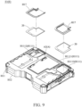
FIG. 9 is a first schematic exploded view of a partial structure of another embodiment of an expansion component according to the present invention; -
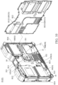
FIG. 10 is a second schematic exploded view of a partial structure of another embodiment of an expansion component according to the present invention; -
FIG. 11 is a schematic cross-sectional view drawn along a division line 11-11 inFIG. 2 ; -
FIG. 12 is a schematic partial enlarged view of acircle 12 inFIG. 11 ; -
FIG. 13 is a schematic three-dimensional external view of an embodiment of a heat dissipation module in an expansion component according to the present invention; and -
FIG. 14 is a schematic cross-sectional view drawn along a division line 14-14 inFIG. 13 . - Referring to
FIG. 1 to FIG. 4 ,FIG. 1 is a schematic three-dimensional external view of an embodiment of an electronic device assembly according to the present invention;FIG. 2 is a first schematic three-dimensional exploded diagram of an embodiment of an electronic device assembly according to the present invention;FIG. 3 is a second schematic three-dimensional exploded diagram of an embodiment of an electronic device assembly according to the present invention; andFIG. 4 is a schematic cross-sectional view drawn along a division line 4-4 inFIG. 1 . - The present invention provides an electronic device assembly, including a plurality of overlapping electronic devices E. The electronic devices E include cases H and electronic components A respectively, each of the cases H has an accommodating space S, the electronic components A are assembled in the accommodating space 5 of each of the cases H, and the electronic components A in adjacent cases H are assembled in an overlapping manner in the two cases H and can be electrically connected to each other. Therefore, the electronic device assembly may use the accommodating spaces S of the plurality of electronic devices E without external wiring to increase a quantity and types of assembled electronic components A, thereby satisfying diversified electronic function expansion.
- Referring to
FIG. 4 , in the electronic device assembly, the cases H and different electronic components A arranged inside the cases may be matched and combined into electronic devices E with different function orientations. The electronic components A may be circuit boards, connectors, storage elements, or power supply elements with different function orientations. - Referring to
FIG. 1 , in some embodiments, the electronic device assembly includes two electronic devices E, where each of the electronic devices E includes a case H. An example in which the two electronic devices E are respectively an expansion component E1 and a host E2 is used below for description, but the present invention is not limited thereto. - Referring to
FIG. 4 , for clear description, in some embodiments in which the electronic device assembly includes the two electronic devices E, the cases H include a first case H1 and a second case H2, where the first case H1 includes a first accommodating space S1, the second case H2 includes a second accommodating space S2, the first case H1 is a part of the expansion component E1, and the second case H2 is a part of the host E2. - Referring to
FIG. 4 , the electronic device assembly includes the expansion component E1 and the host E2. The expansion component E1 includes the first accommodating space S1, the host E2 includes the second accommodating space S2, and different electronic components A are respectively arranged in the first accommodating space S1 and the second accommodating space S2. When the host E2 is assembled to the expansion component E1, one surface of the expansion component E1 abuts against and is electrically connected to one surface of the host E2, to increase spaces of the electronic device assembly for assembling the electronic components A and functions that can be provided by the electronic device assembly. - Referring to
FIG. 3 andFIG. 4 , in some embodiments, the electronic components A include a first circuit board A1 and a first connector A2 arranged in the first accommodating space S1 of the expansion component E1 and a main circuit board A3 and a main connector A4 arranged in the second accommodating space S2 of the host E2. In the embodiments, the main circuit board A3 may be a main board, and the first circuit board A1 is various expansion circuit boards that can cooperate with the main board, but the present invention is not limited thereto. - Referring to
FIG. 3 andFIG. 4 , in the embodiments, the expansion component E1 includes the first case H1, the first circuit board A1, and at least one first connector A2. The first case H1 includes a top plate H11 and a bottom plate H12 that are opposite to each other, where the first accommodating space S1 is formed between the top plate H11 and the bottom plate H12, and the top plate H11 is provided with an opening H111. The first circuit board A1 is arranged in the first accommodating space S1. The first connector A2 is electrically connected to the first circuit board A1, and the first connector A2 is exposed from the top plate H11 at the opening H111. It should be noted that as shown inFIG. 3 , the opening H111 is further equipped with a plate that corresponds to a contour shape of the opening H111, and a through hole for the first connector A2 to pass through is provided on the plate, to prevent external water vapor or dust from entering the first case H1 at the opening H111. However, the opening H111 may not be provided with the plate, so that different electronic components A in the first case H1 pass through the opening H111. The present invention is not limited thereto. - Referring to
FIG. 3 andFIG. 4 , the host E2 includes the second case H2, the main circuit board A3, and at least one main connector A4. The second case H2 includes a first surface H21 and a second surface H22 that are opposite to each other, where the second accommodating space S2 is formed between the first surface H21 and the second surface H22. The main circuit board A3 is arranged in the second accommodating space S2. The main connector A4 is electrically connected to the main circuit board A3 and exposed from the second surface H22. After the host E2 is assembled to the expansion component E1, the second surface H22 of the second case H2 covers the top plate H11 of the first case H1 and the opening H111, and the first connector A2 is electrically connected to the main connector A4. - Therefore, the main circuit board A3 of the host E2 is electrically connected to the first connector A2 of the expansion component E1 by the main connector A4, so that the host E2 can be electrically connected to the first circuit board A1 inside the expansion component E1, to provide function expansion, and the first accommodating space S1 and the second accommodating space S2 are used together to increase the quantity and the types of assembled electronic components A, thereby providing more diversified functions and satisfying more diverse usage demands.
- Referring to
FIG. 1 to FIG. 4 , in some embodiments, the case H (that is, the first case H1) of the expansion component E1 and the case H (that is, the second case H2) of the host E2 are six-sided cubic structures with corresponding appearance shapes. In the embodiments, the first case H1 further includes a first side edge H13, a second side edge H14, a third side edge H15, and a fourth side edge H16 that are sequentially connected, where the first side edge H13, the second side edge H14, the third side edge H15, and the fourth side edge H16 are respectively connected between the top plate H11 and the bottom plate H12 to form the first accommodating space S1. In the embodiments, a shape and a size of the second surface H22 of the case H (the second case H2) of the host E2 correspond to shapes and sizes of the top plate H11 and the bottom plate H12 of the first case H1, so that after the expansion component E1 and the host E2 are assembled, the expansion component and the host E2 have flush outer contours and have an integrated appearance. In addition, a position of the first connector A2 on the top plate H11 corresponds to a position of the main connector A4 on the second surface H22. In this way, when the expansion component E1 and the host E2 are assembled in an overlapping manner, the first connector A2 can be electrically connected to the main connector A4, to achieve expansion. - Referring to
FIG. 4 , in some embodiments, the expansion component E1 further includes apartition 10, where thepartition 10 is parallel to the top plate H11 and the bottom plate H12 and is arranged in the first accommodating space S1. In this way, thepartition 10 is located between the top plate H11 and the bottom plate H12 and can divide the first accommodating space S1 into an upper compartment S11 and a lower compartment 512. Therefore, electronic components A with different function orientations may be respectively arranged in the upper compartment 511 and the lower compartment S12, to provide more diversified functional expansion. - Referring to
FIG. 4 , in some embodiments, the electronic components A further include a second circuit board A5, a plurality of batteries A6, and a second connector A7. In the embodiments, the first circuit board A1 is arranged in the upper compartment 511 of the expansion component E1, the second circuit board A5 and the batteries A6 are arranged in the lower compartment S12 and are electrically connected to each other, and the second connector A7 penetrates thepartition 10 and is electrically connected to the first circuit board A1 and the second circuit board A5. Therefore, the main circuit board A3, the first circuit board A1, and the second circuit board A5 may be configured in the electronic device assembly, to provide diversified functional expansion. In addition, the main circuit board A3 is electrically connected to the first circuit board A1, and the first circuit board A1 is electrically connected to the second circuit board A5 and the batteries A6, so that the batteries A6 arranged in the first accommodating space S1 can simultaneously supply power to the electronic components A in the first accommodating space S1 and the second accommodating space S2 without assembling the battery A6 in the second accommodating space S2, to improve a degree of freedom in space utilization of the second accommodating space S2. It should be noted that the first circuit board A1 and the second circuit board A5 may be replaced with circuit boards with different function orientations according to usage requirements, for example, bus circuit boards, display cards, network cards, or redundant array of independent disks (RAID) cards, but the present invention is not limited thereto. - Referring to
FIG. 2 , in some embodiments, the expansion component E1 further includes awaterproof member 20, where thewaterproof member 20 is arranged around the opening H111. Therefore, it is ensured that the external water vapor cannot enter the first accommodating space S1 from the opening H111 of the expansion component E1, to ensure waterproofness of the expansion component E1. - Referring to
FIG. 5 , in some embodiments, there are a plurality of openings H111 of the first case H1. In the embodiments, the openings H111 include a first opening H1111 and a second opening H1112, where the first opening H1111 is located in the middle of the top plate H11. In this embodiment, the middle of the top plate H11 is not limited to a centroid position of the top plate H11, and the middle of the top plate H11 means that an outer contour of the first opening H1111 does not abut against any one of the first side edge H13, the second side edge H14, the third side edge H15, and the fourth side edge H16. In the embodiments, the first connector A2 is exposed from the first opening H1111. - Referring to
FIG. 5 andFIG. 6 , the expansion component E1 of the electronic device assembly further includes aheat dissipation module 30, to dissipate heat for the electronic components A in the expansion component E1. In some embodiments, theheat dissipation module 30 includes a firstheat dissipation module 30A and a secondheat dissipation module 30B, where the firstheat dissipation module 30A is arranged close to the top plate H11 (as shown inFIG. 5 ), and the secondheat dissipation module 30B is arranged close to the bottom plate H12 (as shown inFIG. 6 ). Therefore, heat dissipation is fully performed inside the expansion component E1 through theheat dissipation module 30. It should be noted that the firstheat dissipation module 30A or the secondheat dissipation module 30B may be separately arranged in the expansion component E1, or the firstheat dissipation module 30A and the secondheat dissipation module 30B may be simultaneously arranged. The present invention is not limited thereto. - Referring to
FIG. 5 , in some embodiments, the firstheat dissipation module 30A includes afan 31 and aheat dissipation pipe 32, the top plate H11 of the first case H1 further includes an assembly groove H112, and the second opening H1112 is adjacent to any two adjacent side edges of the first side edge H13, the second side edge H14, the third side edge H15, and the fourth side edge H16. Referring toFIG. 5 , the second opening H1112 is adjacent to the first side edge H13 and the second side edge H14, and the assembly groove H112 is located at a position corresponding to the second opening H1112 and is recessed from the top plate H11 to the bottom plate H12. - Referring to
FIG. 5 andFIG. 6 , in the embodiments, thefan 31 of the firstheat dissipation module 30A is assembled in the assembly groove H112, one end of theheat dissipation pipe 32 corresponds to a position of thefan 31, and the other end of theheat dissipation pipe 32 extends to the top plate H11 and corresponds to positions of the electronic components A inside the expansion component E1. Therefore, theheat dissipation pipe 32 can absorb heat generated by the electronic components A inside the expansion component E1 and conduct the heat to the position corresponding to thefan 31 for heat dissipation. - Referring to
FIG. 5 andFIG. 6 , in some embodiments, the top plate H11 of the expansion component E1 further includes a heat dissipation pipe groove H113, where the heat dissipation pipe groove H113 is recessed from the top plate H11 to the bottom plate H12, one end of the heat dissipation pipe groove H113 is engaged with the second opening H1112, and the other end of the heat dissipation pipe groove H113 extends to the positions of the electronic components A in the expansion component E1. Therefore, even if the top plate H11 of the expansion component E1 is equipped with theheat dissipation pipe 32, because theheat dissipation pipe 32 is accommodated in the heat dissipation pipe groove H113, surface flatness can still be maintained, thereby ensuring that the host E2 can be smoothly assembled to the expansion component E1. - Referring to
FIG. 4 andFIG. 6 , in some embodiments, the electronic components A of the electronic device assembly further include a disk array A8. In the embodiments, the disk array A8 is accommodated in the upper compartment 511 of the expansion component E1 and is electrically connected to the first circuit board A1, and the disk array A8 is located between the assembly groove H112 and the third side edge H15. Herein, theheat dissipation pipe 32 extends between the assembly groove H112 and the third side edge H15 to correspond to a position of the disk array A8, so as to fully dissipate heat for the disk array A8. - Referring to
FIG. 4 andFIG. 6 , in some embodiments, there are two disk arrays A8. In the embodiments, a quantity of second openings H1112 of the top plate H11 and a quantity of firstheat dissipation modules 30A are equal to a quantity of disk arrays A8. In the embodiments, the two disk arrays A8 are respectively assembled on two sides of the first circuit board A1 (where one group of disk arrays A8 is displayed inFIG. 4 ), one second opening H1112 is adjacent to the first side edge H13 and the second side edge H14, the other second opening H1112 is adjacent to the first side edge H13 and the fourth side edge H16, and aheat dissipation pipe 32 of each firstheat dissipation module 30A extends between the third side edge H15 and the two second openings H1112. Therefore, the firstheat dissipation modules 30A can dissipate heat for the two disk arrays A8 accommodated in the upper compartment 511. - Referring to
FIG. 7 andFIG. 8 ,FIG. 7 is a schematic cross-sectional view drawn along a division line 7-7 inFIG. 3 .FIG. 8 is a schematic diagram of a partial structure of an embodiment of an expansion component according to the present invention.FIG. 8 is a schematic diagram in which configurations inside an upper compartment 511 are exposed without displaying a top plate H11 in a first case H1. In the embodiments, the electronic component A accommodated in the upper compartment 511 in the electronic device assembly and electrically connected to the first circuit board A1 is a bus apparatus A9 (for example, a PCI-E card, a PCI-E interface display card, a PCI-E interface SSD, or another PCI-E interface high-speed signal transmission apparatus). In the embodiments, the firstheat dissipation module 30A includes thefan 31 that is accommodated in the upper compartment 511. Herein, thefan 31 is electrically connected to the first circuit board A1, thefan 31 is provided with anair outlet 3112, and theair outlet 3112 of thefan 31 faces toward the bus apparatus A9 to dissipate heat for the bus apparatus A9. - Referring to
FIG. 8 andFIG. 9 , in some embodiments in which the firstheat dissipation module 30A is accommodated in the upper compartment 511 rather than arranged at the second opening H1112, the first case H1 does not include the assembly groove H112. In the embodiments, the first case H1 further includes a waterproof cover plate H17, where a shape and a size of the waterproof cover plate H17 corresponds to the shape and the size of the second opening H1112, and the waterproof cover plate H17 covers the second opening H1112, to close the second opening H1112, thereby ensuring waterproofness inside the first case H1. - Referring to
FIG. 10 to FIG. 12 , in some embodiments, the secondheat dissipation module 30B is arranged in the lower compartment S12 and can simultaneously dissipate heat for the electronic components A inside the upper compartment S11 and the lower compartment 512. In the embodiments, the electronic components A accommodated in the upper compartment 511 abut against thepartition 10. - Referring to
FIG. 10 to FIG. 12 , the secondheat dissipation module 30B includes thefan 31 and adiversion case 33. Thediversion case 33 includes aninput section 331 and anoutput section 332 that are connected. An angle is defined between an extending direction of theinput section 331 and an extending direction of theoutput section 332, thediversion case 33 is accommodated in the lower compartment 512, and theoutput section 332 abuts against thepartition 10 and one of the electronic components A located in the lower compartment 512. Thefan 31 is arranged at a junction of theinput section 331 and theoutput section 332. - Therefore, when the
fan 31 of the secondheat dissipation module 30B runs, an airflow is led into theinput section 331 of thediversion case 33 and then is led out from theoutput section 332, heat generated by thepartition 10 and the electronic component A located in the lower compartment S12 against which theoutput section 332 abut can be conducted outside the expansion component E1 through the airflow, and heat dissipation can be simultaneously performed on the electronic components A accommodated in the upper compartment 511 and the lower compartment S12 by using the secondheat dissipation module 30B, to reduce a space occupied by assembling the heat dissipation structure or the internal diversion device, and improve utilization of the internal space of the electronic device assembly. - Referring to
FIG. 10 andFIG. 13 , in some embodiments, theinput section 331 and theoutput section 332 of thediversion case 33 are connected to form an L-shape. That is, the angle between the extending direction of theinput section 331 and the extending direction of theoutput section 332 is 90 degrees. Therefore, a position at which the secondheat dissipation module 30B introduces the airflow and a position at which the airflow is led out for heat dissipation are not on a same straight line but can meet position configuration requirements of different electronic components A inside the lower compartment 512. - Referring to
FIG. 10 andFIG. 13 , in some embodiments, thediversion case 33 includes a connectingsection 333, where the connectingsection 333 is located between theinput section 331 and theoutput section 332, and thefan 31 is accommodated in the connectingsection 333. In the embodiments, an end of theinput section 331 away from the connectingsection 333 and an end of theoutput section 332 away from the connecting section are respectively inclined relative to the connectingsection 333. Therefore, depths may be configured for a part between the connectingsection 333 and theinput section 331 and a part between theoutput section 332 and the connectingsection 333 for collecting and guiding an airflow, and the end of theinput section 331 away from the connectingsection 333 and the end of theoutput section 332 away from the connecting section may be close to an assembled position of thediversion case 33, to smoothly guide input and output of the airflow. - Referring to
FIG. 10 andFIG. 13 , in some embodiments, theentire diversion case 33 includes anedge 334, theedge 334 surrounds and forms anopening 3341, and theinput section 331, theoutput section 332, and the connectingsection 333 are located within a range of theopening 3341. In the embodiments, the bottom plate H12 of the first case H1 of the expansion component E1 includes a plurality of through holes H121. Theedge 334 of thediversion case 33 abuts against the bottom plate H12 of the first case H1, and theopening 3341 covers the through hole H121. Therefore, the airflow can be smoothly inputted into thediversion case 33 from the bottom plate H12 of the first case H1 and outputted from thediversion case 33, to ensure a diversion effect and a heat dissipation effect of thediversion case 33. - Referring to
FIG. 7 andFIG. 10 , in some embodiments, the through holes H121 of the bottom plate H12 of the first case H1 include a plurality of first through holes H1211 and a plurality of second through holes H1212. Positions of the first through holes H1211 correspond to a position of theinput section 331, and positions of the second through holes H1212 correspond to a position of theoutput section 332, to ensure smoothness of the airflow flowing in and out of thediversion case 33. - Referring to
FIG. 12 to FIG. 14 , in some embodiments, thediversion case 33 includes aninner surface 335. When thediversion case 33 is assembled on the bottom plate H12 of the first case H1, theinner surface 335 faces toward the bottom plate H12, and theinner surface 335 has different depth configurations to be attached to different electronic components A, so as to dissipate heat for a plurality of electronic components A simultaneously. In the embodiments, theoutput section 332 includes a firstheat dissipation section 3321 and a secondheat dissipation section 3322. Theinner surface 335 has a first height L1 between the firstheat dissipation section 3321 and theopening 3341, theinner surface 335 has a second height L2 between the secondheat dissipation section 3322 and theopening 3341, and the first height L1 is different from the second height L2. Therefore, thediversion case 33 may be simultaneously in contact with the electronic components A located inside the lower compartment S12 and the upper compartment S11 through the firstheat dissipation section 3321 and the secondheat dissipation section 3322 and can simultaneously dissipate heat for the electronic components A located inside the upper compartment S11 and the lower compartment 512. - Referring to
FIG. 12 andFIG. 14 , in the embodiments, the first height L1 is less than the second height L2, that is, a distance of theinner surface 335 between the firstheat dissipation section 3321 and theopening 3341 is less than a distance of theinner surface 335 between the secondheat dissipation section 3322 and theopening 3341, and the firstheat dissipation section 3321 is closer to the bottom plate H12 than the secondheat dissipation section 3322. Therefore, the firstheat dissipation section 3321 of thediversion case 33 abuts against the electronic component A located in the lower compartment 512, the secondheat dissipation section 3322 abuts against thepartition 10, and a position of the secondheat dissipation section 3322 corresponds to the position of the electronic component A located in the upper compartment 511. - Referring to
FIG. 12 , in the embodiments in which the electronic component A located in the upper compartment 511 is the bus apparatus A9, the bus apparatus A9 abuts against thepartition 10, and the secondheat dissipation section 3322 of thediversion case 33 abuts against a position at which thepartition 10 corresponds to the bus apparatus A9 to dissipate heat for the bus apparatus A9. In the embodiments, the electronic components A of the expansion component E1 further include a third circuit board A10, where the third circuit board A10 is arranged in the lower compartment S12 and is parallel to and spaced apart from the second circuit board A5, and the third circuit board A10 is closer to the bottom plate H12 than the second circuit board A5. Herein, the firstheat dissipation section 3321 of thediversion case 33 abuts against the third circuit board A10 to dissipate heat for the third circuit board A10. Therefore, a plurality of overlapping electronic components A may be configured in the lower compartment S12 of the expansion component E1, and heat of the overlapping electronic components A can still be fully dissipated by the secondheat dissipation module 30B, to ensure that the electronic components A can smoothly run, thereby ensuring an expansion function of the expansion component E1. - Referring to
FIG. 12 to FIG. 14 , in some embodiments, theoutput section 332 of thediversion case 33 further includes a thirdheat dissipation section 3323, where the firstheat dissipation section 3321, the secondheat dissipation section 3322, and the thirdheat dissipation section 3323 of theoutput section 332 are sequentially connected, and the thirdheat dissipation section 3323 of theoutput section 332 is connected to thefan 31. Therefore, air enters from theinput section 331 of thediversion case 33, then enters thefan 31, and then is discharged sequentially by the thirdheat dissipation section 3323, the secondheat dissipation section 3322, and the firstheat dissipation section 3321 of theoutput section 332. In this way, the heat of all the electronic components A abutting against the firstheat dissipation section 3321, the secondheat dissipation section 3322, and the thirdheat dissipation section 3323 can be dissipated by thediversion case 33. - Referring to
FIG. 12 to FIG. 14 , in some embodiments, theinner surface 335 of thediversion case 33 has a third height L3 between the thirdheat dissipation section 3323 and theopening 3341, where the third height L3 is different from the first height L1 and the second height L2. Therefore, the electronic components A against which the firstheat dissipation section 3321, the secondheat dissipation section 3322, and the thirdheat dissipation section 3323 abut for heat dissipation may be respectively located at different height positions but can still be fully dissipated by thediversion case 33. In the embodiments, the thirdheat dissipation section 3323 abuts against the second circuit board A5, but the present invention is not limited thereto. - Referring to
FIG. 12 to FIG. 14 , in some embodiments, thefan 31 is a centrifugal fan and includes acase 311, where thecase 311 is provided with anair inlet 3111 and anair outlet 3112 that are perpendicular to each other. The thirdheat dissipation section 3323 of theoutput section 332 of thediversion case 33 is flush with theair outlet 3112 of thefan 31. Therefore, an airflow outputted from theair outlet 3112 of thefan 31 can smoothly enter theoutput section 332 from the thirdheat dissipation section 3323, to improve smoothness of the airflow. - Referring to
FIG. 12 to FIG. 14 , in the embodiments in which the thirdheat dissipation section 3323 of thediversion case 33 is flush with thefan 31, the third height L3 is greater than the first height L1 and is less than the second height L2. Therefore, a large amount of air entering theoutput section 332 from thefan 31 can be collected at the secondheat dissipation section 3322 after passing through the thirdheat dissipation section 3323, to obviously dissipate heat for the electronic component A at a position corresponding to thepartition 10, and then is discharged by the firstheat dissipation section 3321 closest to the bottom plate H12. - Referring to
FIG. 12 to FIG. 14 , in some embodiments, theinput section 331 of thediversion case 33 includes aninlet section 3311 and acollecting section 3312 that are sequentially connected, where thecollecting section 3312 is connected between theinlet section 3311 and the connectingsection 333 and is flush with the connectingsection 333. In the embodiments, thefan 31 is arranged in the connectingsection 333 and theair inlet 3111 faces toward theinner surface 335, and a distance is provided between theair inlet 3111 of thefan 31 and theinner surface 335. Therefore, air can enter thefan 31 after being guided by theinput section 331 of thediversion case 33 for thefan 31 to generate an active airflow. - Referring to
FIG. 12 to FIG. 14 , in some embodiments, theinner surface 335 of thediversion case 33 also has the second height L2 between theopening 3341 and thecollecting section 3312, theinner surface 335 of thediversion case 33 also has the second height L2 between theopening 3341 and the connectingsection 333. Therefore, thecollecting section 3312 can collect a large amount of air introduced by theinlet section 3311 into thefan 31, so as to improve a flow rate of air flowing through thediversion case 33 and the heat dissipation efficiency. In addition, because the connectingsection 333 also has the second height L2, when thediversion case 33 is assembled in the lower compartment 512, the connectingsection 333 can also abut against thepartition 10, to increase an area where thepartition 10 abuts against thediversion case 33, thereby improving a support force of thepartition 10 and also improving heat dissipation effect for the electronic components A abutting against thepartition 10. - Referring to
FIG. 12 to FIG. 14 , in some embodiments, the secondheat dissipation module 30B further includes a plurality ofheat dissipation fins 34, where theheat dissipation fins 34 are arranged in thediversion case 33. In the embodiments, the plurality ofheat dissipation fins 34 are respectively arranged in the firstheat dissipation section 3321, the secondheat dissipation section 3322, and theinlet section 3311 of thediversion case 33, and theheat dissipation fins 34 in the firstheat dissipation section 3321, the secondheat dissipation section 3322, and theinlet section 3311 are parallel to and spaced apart from each other. Therefore, a contact area between the air and thediversion case 33 is increased, to improve the heat dissipation effect. - Referring to
FIG. 12 to FIG. 14 , in some embodiments, theinlet section 3311 of theinput section 331 of thediversion case 33 has afirst end 3313 and asecond end 3314, where thesecond end 3314 is closer to thefan 31 than thefirst end 3313 and is connected to thefan 31, a height of theinner surface 335 from thesecond end 3314 to theopening 3341 is greater than a height of theinner surface 335 from thefirst end 3313 to theopening 3341, and thefirst end 3313 is obliquely connected to thesecond end 3314, so that theinlet section 3311 is inclined to the bottom plate H12. In this way, theinlet section 3311 obliquely extends to the bottom plate H12, and air is introduced by the first through hole H1211 of the bottom plate H12, to improve the smoothness of the air entering thediversion case 33. - Referring to
FIG. 12 to FIG. 14 , in some embodiments, theoutput section 332 of thediversion case 33 further includes anoutlet section 3324, where theoutlet section 3324 is connected to the firstheat dissipation section 3321 and is inclined to the firstheat dissipation section 3321, so that theoutlet section 3324 obliquely extends to the bottom plate H12. In this way, theoutlet section 3324 obliquely extends to the bottom plate H12, and air is introduced by the second through hole H1212 of the bottom plate H12, to improve the smoothness of the air entering thediversion case 33. - Referring to
FIG. 12 to FIG. 14 , in some embodiments, theinner surface 335 of thediversion case 33 is inclined relative to the bottom plate H12 in an extending direction between the firstheat dissipation section 3321 and the secondheat dissipation section 3322. Therefore, it is ensured that the air in the secondheat dissipation section 3322 farthest from theopening 3341 can smoothly flow to the firstheat dissipation section 3321, to ensure the smoothness of the heat dissipation airflow.
Claims (16)
- An expansion component (E1), characterized by comprising:a case (H, H1), comprising a bottom plate (H12), a top plate (H11), and an accommodating space (S) located between the bottom plate (H12) and the top plate (H11);a partition (10), arranged in the accommodating space (S) and parallel to the bottom plate (H12), wherein the partition (10) divides the accommodating space (S) into an upper compartment (511) and a lower compartment (S12);a plurality of electronic components (A), scattered in the upper compartment (S11) and the lower compartment (S12), wherein one of the electronic components (A) located in the upper compartment (511) abuts against the partition (10); anda heat dissipation module (30), arranged in the case (H, H1) and comprising:a diversion case (33), comprising an input section (331) and an output section (332) that are connected, wherein an angle is defined between an extending direction of the input section (331) and an extending direction of the output section (332), the diversion case (33) is accommodated in the lower compartment (S12), and the output section (332) abuts against the partition (10) and one of the electronic components (A) located in the lower compartment (S12); anda fan (31), arranged at a junction of the input section (331) and the output section (332).
- The expansion component (E1) according to claim 1, wherein the bottom plate (H12) comprises a plurality of through holes (H121), and the diversion case (33) comprises an edge (334), the edge (334) surrounds and forms an opening (3341), the edge (334) abuts against the bottom plate (H12), and the opening (3341) covers the through holes (H121).
- The expansion component (E1) according to claim 2, wherein the through holes (H121) comprise a plurality of first through holes (H1211) and a plurality of second through holes (H1212), the first through holes (H1211) correspond to a position of the input section (331), and the second through holes (H1212) correspond to a position of the output section (332).
- The expansion component (E1) according to claim 2, wherein the diversion case (33) comprises an inner surface (335), the inner surface (335) faces toward the bottom plate (H12), the output section (332) comprises a first heat dissipation section (3321) and a second heat dissipation section (3322), the inner surface (335) has a first height (L1) between the first heat dissipation section (3321) and the opening (3341), the inner surface (335) has a second height (L2) between the second heat dissipation section (3322) and the opening (3341), and the first height (L1) is different from the second height (L2).
- The expansion component (E1) according to claim 4, wherein the first heat dissipation section (3321) abuts against the electronic component (A) located in the lower compartment (S12), and the second heat dissipation section (3322) abuts against a position at which the partition (10) corresponds to the electronic component (A) located in the upper compartment (S11).
- The expansion component (E1) according to claim 4, wherein the first heat dissipation section (3321) is farther away from the fan (31) than the second heat dissipation section (3322), and the first height (L1) is less than the second height (L2).
- The expansion component (E1) according to claim 6, wherein the inner surface (335) is inclined to the bottom plate (H12) in an extending direction between the first heat dissipation section (3321) and the second heat dissipation section (3322).
- The expansion component (E1) according to claim 4, wherein the output section (332) further comprises a third heat dissipation section (3323), the inner surface (335) has a third height (L3) between the third heat dissipation section (3323) and the opening (3341), and the third height (L3) is different from the first height (L1) and the second height (L2).
- The expansion component (E1) according to claim 8, wherein the third heat dissipation section (3323) is closer to the fan (31) than the first heat dissipation section (3321) and the second heat dissipation section (3322), and the third heat dissipation section (3323) abuts against another electronic component (A) located in the lower compartment (S12).
- The expansion component (E1) according to claim 8, wherein the third heat dissipation section (3323) is flush with the fan (31), and the third height (L3) is greater than the first height (L1) and less than the second height (L2).
- The expansion component (E1) according to claim 4, wherein the input section (331) of the diversion case (33) comprises an inlet section (3311), the inlet section (3311) has a first end (3313) and a second end (3314), the inner surface (335) is inclined to the bottom plate (H12) at the inlet section (3311), the second end (3314) is closer to the fan (31) than the first end (3313), and a height of the inner surface (335) from the second end (3314) to the opening (3341) is greater than a height of the inner surface (335) from the first end (3313) to the opening (3341).
- The expansion component (E1) according to claim 11, wherein the input section (331) of the diversion case (33) further comprises a collecting section (3312), the collecting section (3312) is located between the inlet section (3311) and the fan (31), the inner surface (335) has the second height (L2) from the collecting section (3312) to the opening (3341), and the collecting section (3312) abuts against the partition (10).
- The expansion component (E1) according to claim 4, wherein the fan (31) comprises a case (311), the case (311) is provided with an air inlet (3111) and an air outlet (3112) that are perpendicular to each other, the air inlet (3111) faces toward the inner surface (335) and is spaced apart from the inner surface (335) by a distance, and the air outlet (3112) faces toward the output section (332).
- An expansion component (E1), characterized by comprising:a case (H, H1), comprising a bottom plate (H12), a top plate (H11), and an accommodating space (S) located between the bottom plate (H12) and the top plate (H11);a partition (10), arranged in the accommodating space (S) and parallel to the bottom plate (H12), wherein the partition (10) divides the accommodating space (S) into an upper compartment (511) and a lower compartment (S12);a plurality of electronic components (A), scattered in the upper compartment (S11) and the lower compartment (S12), wherein one of the electronic components (A) located in the upper compartment (511) abuts against the partition (10); anda heat dissipation module (30), arranged in the case (H, H1) and comprising:a diversion case (33), comprising an input section (331) and an output section (332) that are connected to form an L-shape, wherein the diversion case (33) is accommodated in the lower compartment (S12) and fixed to the bottom plate (H12), and the output section (332) abuts against the partition (10) and one of the electronic components (A) located in the lower compartment (S12); anda fan (31), arranged at a junction of the input section (331) and the output section (332).
- An electronic device assembly, characterized by comprising:the expansion component (E1) as claimed in any one of the preceding claims, comprising:
a first connector (A2), electrically connected to a first circuit board (A1) and exposed from the top plate (H11) at an opening (H111), wherein the top plate (H11) is provided with the opening (H111); anda host (E2), comprising:a second case (H, H2), having a second accommodating space (S2);a main circuit board (A3), accommodated in the second accommodating space (S2); anda main connector (A4), electrically connected to the main circuit board (A3) and arranged on a surface of the second case (H, H2), wherein after the host (E2) is assembled to the expansion component (E1), the second case (H, H2) covers the top plate (H11) of the first case (H, H1) and the opening (H111), and the first connector (A2) is electrically connected to the main connector (A4). - A heat dissipation module (30), characterized by comprising:a diversion case (33), comprising an input section (331), an output section (332), and a connecting section (333) that connects the input section (331) and the output section (332), wherein an angle is defined between an extending direction of the input section (331) and an extending direction of the output section (332), and an end of the input section (331) away from the connecting section (333) and an end of the output section (332) away from the connecting section (333) are respectively inclined relative to the connecting section (333); anda fan (31), accommodated in the connecting section (333).
Applications Claiming Priority (3)
| Application Number | Priority Date | Filing Date | Title |
|---|---|---|---|
| US202263309463P | 2022-02-11 | 2022-02-11 | |
| US202263351422P | 2022-06-12 | 2022-06-12 | |
| CN202211467557.7A CN116600521B (en) | 2022-02-11 | 2022-11-22 | Electronic device assembly and its expansion components and heat dissipation modules |
Publications (2)
| Publication Number | Publication Date |
|---|---|
| EP4239445A2 true EP4239445A2 (en) | 2023-09-06 |
| EP4239445A3 EP4239445A3 (en) | 2023-11-15 |
Family
ID=85150682
Family Applications (1)
| Application Number | Title | Priority Date | Filing Date |
|---|---|---|---|
| EP23155305.8A Pending EP4239445A3 (en) | 2022-02-11 | 2023-02-07 | Electronic device assembly, expansion component thereof, and heat dissipation module |
Country Status (3)
| Country | Link |
|---|---|
| US (1) | US12309963B2 (en) |
| EP (1) | EP4239445A3 (en) |
| AU (1) | AU2023200259B2 (en) |
Family Cites Families (28)
| Publication number | Priority date | Publication date | Assignee | Title |
|---|---|---|---|---|
| JP3329637B2 (en) | 1995-10-20 | 2002-09-30 | 株式会社東芝 | Expansion station for electronic equipment and electronic equipment system |
| TW397225U (en) | 1998-05-08 | 2000-07-01 | Cheng Feng Tzau | An improvement on the heat sink for a CPU |
| JP3581318B2 (en) * | 2001-02-06 | 2004-10-27 | 株式会社東芝 | Cooling device used for electronic equipment system and portable electronic equipment |
| TW516662U (en) | 2001-03-21 | 2003-01-01 | Micro Star Int Co Ltd | Air flow directing device with flow rate distribution |
| TW506555U (en) | 2001-04-06 | 2002-10-11 | Advantech Co Ltd | Modular industrial computer |
| US6989988B2 (en) | 2003-02-21 | 2006-01-24 | Hewlett-Packard Development Company, L.P. | Duct for cooling multiple components in a processor-based device |
| TWM259198U (en) | 2004-06-30 | 2005-03-11 | S S I Comp Corp | Expansion device of notebook |
| TW200733856A (en) * | 2006-02-20 | 2007-09-01 | Sunonwealth Electr Mach Ind Co | Composite heat-dissipating module |
| JP2011077403A (en) * | 2009-09-30 | 2011-04-14 | Toshiba Corp | Electronic device |
| TWM386520U (en) | 2010-02-09 | 2010-08-11 | Wistron Corp | Waterproof mechanism, electronic device with such a waterproof mechanism, and combination of external electronic apparatus with such an electronic device |
| TWI414685B (en) | 2010-09-21 | 2013-11-11 | Sunonwealth Electr Mach Ind Co | Cooling fan |
| US9795044B2 (en) | 2011-08-22 | 2017-10-17 | Catalyst Lifestyle Limited | Waterproof case |
| TWI507852B (en) | 2013-10-29 | 2015-11-11 | Wistron Corp | Docking station and electronic apparatus |
| JP6307884B2 (en) * | 2014-01-08 | 2018-04-11 | 富士通株式会社 | Electronics |
| CN106062660A (en) * | 2014-02-20 | 2016-10-26 | 鲁斯特科有限责任公司 | Laptop Cooling Stand |
| CN205880770U (en) | 2015-05-25 | 2017-01-11 | 周奋豪 | Heat radiation structure of independent display card of computer and mounting structure thereof |
| EP3352548B1 (en) * | 2015-09-18 | 2020-10-28 | Toray Industries, Inc. | Electronic device housing |
| CN205082113U (en) | 2015-09-24 | 2016-03-09 | 杭州奢淘科技有限公司 | Electronic product heat radiation structure |
| US10481656B2 (en) | 2015-12-10 | 2019-11-19 | Dell Products L.P. | Systems and methods for cooling portable information handling systems |
| KR102551121B1 (en) * | 2016-09-01 | 2023-07-05 | 엘지전자 주식회사 | Control unit and display device comprising it |
| JP6613283B2 (en) * | 2017-10-31 | 2019-11-27 | ファナック株式会社 | Cooling structure and housing |
| EP3493098A1 (en) | 2017-11-30 | 2019-06-05 | ELATEC GmbH | Rfid reader with turnable usb connector |
| US10831248B2 (en) | 2018-05-09 | 2020-11-10 | Adesa, Inc. | Mobile device temperature-regulating case |
| US10468812B1 (en) | 2018-10-12 | 2019-11-05 | Getac Technology Corporation | Electrical connector structure and waterproof ring thereof |
| CN209962173U (en) | 2019-08-09 | 2020-01-17 | 深圳市凯星辉科技有限公司 | Docking station with wireless charging function |
| CN110568910B (en) | 2019-08-28 | 2024-03-22 | 英业达科技有限公司 | Host computer for vehicle and computer system for vehicle |
| TWM593578U (en) | 2019-12-17 | 2020-04-11 | 勁碩股份有限公司 | Cem-convertible expansion module |
| CN212543377U (en) * | 2020-03-19 | 2021-02-12 | 华为技术有限公司 | Wireless charger |
-
2023
- 2023-01-18 AU AU2023200259A patent/AU2023200259B2/en active Active
- 2023-02-06 US US18/164,922 patent/US12309963B2/en active Active
- 2023-02-07 EP EP23155305.8A patent/EP4239445A3/en active Pending
Also Published As
| Publication number | Publication date |
|---|---|
| US20230276596A1 (en) | 2023-08-31 |
| US12309963B2 (en) | 2025-05-20 |
| AU2023200259A1 (en) | 2023-08-31 |
| EP4239445A3 (en) | 2023-11-15 |
| AU2023200259B2 (en) | 2024-09-26 |
Similar Documents
| Publication | Publication Date | Title |
|---|---|---|
| EP1094696B1 (en) | Connector | |
| US20070081308A1 (en) | Computer system | |
| US6970346B2 (en) | Redundant power supply wirelessly connected to motherboard | |
| US20210167554A1 (en) | Polarization feature for a receptacle cage | |
| EP4239446A2 (en) | Electronic device assembly and expansion component thereof | |
| CN110568910A (en) | Vehicle host and vehicle computer system | |
| CN115275716A (en) | Shield can assembly and socket connector assembly | |
| EP4239445A2 (en) | Electronic device assembly, expansion component thereof, and heat dissipation module | |
| EP0838749B1 (en) | Thin structure information processing apparatus | |
| EP4510800A1 (en) | Electronic device | |
| TWI821040B (en) | Electronic device assembly and expansion component | |
| CN116600521B (en) | Electronic device assembly and its expansion components and heat dissipation modules | |
| CN103035266B (en) | Connector module | |
| CN116600521A (en) | Electronic device combination and its expansion components and heat dissipation module | |
| CN211351066U (en) | Connector and communication device | |
| WO2013176488A1 (en) | Keyboard integrated with system unit of computer | |
| US20240097374A1 (en) | Receptacle assembly, cage and mounting method | |
| EP4510797A1 (en) | Electronic device | |
| CN214376276U (en) | Heat dissipation device for server case and server case | |
| CN215006481U (en) | Heat dissipation case structure that contains fan | |
| CN223871034U (en) | PCIe device with heat dissipation function | |
| JP2009104665A (en) | Thin structure information processing device | |
| CN223582411U (en) | Hard disk system and hard disk frame thereof | |
| TWI917163B (en) | Dedicated graphics card cooling case | |
| CN222319750U (en) | Storage array device and server equipment with same |
Legal Events
| Date | Code | Title | Description |
|---|---|---|---|
| PUAI | Public reference made under article 153(3) epc to a published international application that has entered the european phase |
Free format text: ORIGINAL CODE: 0009012 |
|
| STAA | Information on the status of an ep patent application or granted ep patent |
Free format text: STATUS: THE APPLICATION HAS BEEN PUBLISHED |
|
| AK | Designated contracting states |
Kind code of ref document: A2 Designated state(s): AL AT BE BG CH CY CZ DE DK EE ES FI FR GB GR HR HU IE IS IT LI LT LU LV MC ME MK MT NL NO PL PT RO RS SE SI SK SM TR |
|
| PUAL | Search report despatched |
Free format text: ORIGINAL CODE: 0009013 |
|
| AK | Designated contracting states |
Kind code of ref document: A3 Designated state(s): AL AT BE BG CH CY CZ DE DK EE ES FI FR GB GR HR HU IE IS IT LI LT LU LV MC ME MK MT NL NO PL PT RO RS SE SI SK SM TR |
|
| RIC1 | Information provided on ipc code assigned before grant |
Ipc: G06F 1/20 20060101ALI20231012BHEP Ipc: G06F 1/16 20060101AFI20231012BHEP |
|
| STAA | Information on the status of an ep patent application or granted ep patent |
Free format text: STATUS: REQUEST FOR EXAMINATION WAS MADE |
|
| 17P | Request for examination filed |
Effective date: 20240125 |
|
| RBV | Designated contracting states (corrected) |
Designated state(s): AL AT BE BG CH CY CZ DE DK EE ES FI FR GB GR HR HU IE IS IT LI LT LU LV MC ME MK MT NL NO PL PT RO RS SE SI SK SM TR |
|
| STAA | Information on the status of an ep patent application or granted ep patent |
Free format text: STATUS: EXAMINATION IS IN PROGRESS |
|
| 17Q | First examination report despatched |
Effective date: 20250724 |
|
| GRAP | Despatch of communication of intention to grant a patent |
Free format text: ORIGINAL CODE: EPIDOSNIGR1 |
|
| STAA | Information on the status of an ep patent application or granted ep patent |
Free format text: STATUS: GRANT OF PATENT IS INTENDED |
|
| INTG | Intention to grant announced |
Effective date: 20260102 |
|
| GRAS | Grant fee paid |
Free format text: ORIGINAL CODE: EPIDOSNIGR3 |
|
| GRAA | (expected) grant |
Free format text: ORIGINAL CODE: 0009210 |
|
| STAA | Information on the status of an ep patent application or granted ep patent |
Free format text: STATUS: THE PATENT HAS BEEN GRANTED |