EP4239366A2 - Appareil de traitement d'image, appareil de mesure de distance et procédé de traitement d'image - Google Patents
Appareil de traitement d'image, appareil de mesure de distance et procédé de traitement d'image Download PDFInfo
- Publication number
- EP4239366A2 EP4239366A2 EP22193424.3A EP22193424A EP4239366A2 EP 4239366 A2 EP4239366 A2 EP 4239366A2 EP 22193424 A EP22193424 A EP 22193424A EP 4239366 A2 EP4239366 A2 EP 4239366A2
- Authority
- EP
- European Patent Office
- Prior art keywords
- light signal
- image
- distance
- scanning
- frames
- Prior art date
- Legal status (The legal status is an assumption and is not a legal conclusion. Google has not performed a legal analysis and makes no representation as to the accuracy of the status listed.)
- Granted
Links
Images


Classifications
-
- G—PHYSICS
- G06—COMPUTING OR CALCULATING; COUNTING
- G06T—IMAGE DATA PROCESSING OR GENERATION, IN GENERAL
- G06T5/00—Image enhancement or restoration
- G06T5/50—Image enhancement or restoration using two or more images, e.g. averaging or subtraction
-
- G—PHYSICS
- G01—MEASURING; TESTING
- G01S—RADIO DIRECTION-FINDING; RADIO NAVIGATION; DETERMINING DISTANCE OR VELOCITY BY USE OF RADIO WAVES; LOCATING OR PRESENCE-DETECTING BY USE OF THE REFLECTION OR RERADIATION OF RADIO WAVES; ANALOGOUS ARRANGEMENTS USING OTHER WAVES
- G01S7/00—Details of systems according to groups G01S13/00, G01S15/00, G01S17/00
- G01S7/48—Details of systems according to groups G01S13/00, G01S15/00, G01S17/00 of systems according to group G01S17/00
- G01S7/481—Constructional features, e.g. arrangements of optical elements
- G01S7/4817—Constructional features, e.g. arrangements of optical elements relating to scanning
-
- G—PHYSICS
- G01—MEASURING; TESTING
- G01S—RADIO DIRECTION-FINDING; RADIO NAVIGATION; DETERMINING DISTANCE OR VELOCITY BY USE OF RADIO WAVES; LOCATING OR PRESENCE-DETECTING BY USE OF THE REFLECTION OR RERADIATION OF RADIO WAVES; ANALOGOUS ARRANGEMENTS USING OTHER WAVES
- G01S17/00—Systems using the reflection or reradiation of electromagnetic waves other than radio waves, e.g. lidar systems
- G01S17/02—Systems using the reflection of electromagnetic waves other than radio waves
- G01S17/06—Systems determining position data of a target
- G01S17/42—Simultaneous measurement of distance and other co-ordinates
-
- G—PHYSICS
- G01—MEASURING; TESTING
- G01S—RADIO DIRECTION-FINDING; RADIO NAVIGATION; DETERMINING DISTANCE OR VELOCITY BY USE OF RADIO WAVES; LOCATING OR PRESENCE-DETECTING BY USE OF THE REFLECTION OR RERADIATION OF RADIO WAVES; ANALOGOUS ARRANGEMENTS USING OTHER WAVES
- G01S17/00—Systems using the reflection or reradiation of electromagnetic waves other than radio waves, e.g. lidar systems
- G01S17/88—Lidar systems specially adapted for specific applications
- G01S17/89—Lidar systems specially adapted for specific applications for mapping or imaging
- G01S17/894—3D imaging with simultaneous measurement of time-of-flight at a 2D array of receiver pixels, e.g. time-of-flight cameras or flash lidar
-
- G—PHYSICS
- G01—MEASURING; TESTING
- G01S—RADIO DIRECTION-FINDING; RADIO NAVIGATION; DETERMINING DISTANCE OR VELOCITY BY USE OF RADIO WAVES; LOCATING OR PRESENCE-DETECTING BY USE OF THE REFLECTION OR RERADIATION OF RADIO WAVES; ANALOGOUS ARRANGEMENTS USING OTHER WAVES
- G01S7/00—Details of systems according to groups G01S13/00, G01S15/00, G01S17/00
- G01S7/48—Details of systems according to groups G01S13/00, G01S15/00, G01S17/00 of systems according to group G01S17/00
- G01S7/483—Details of pulse systems
- G01S7/486—Receivers
- G01S7/4865—Time delay measurement, e.g. time-of-flight measurement, time of arrival measurement or determining the exact position of a peak
-
- G—PHYSICS
- G06—COMPUTING OR CALCULATING; COUNTING
- G06T—IMAGE DATA PROCESSING OR GENERATION, IN GENERAL
- G06T5/00—Image enhancement or restoration
- G06T5/73—Deblurring; Sharpening
-
- G—PHYSICS
- G06—COMPUTING OR CALCULATING; COUNTING
- G06T—IMAGE DATA PROCESSING OR GENERATION, IN GENERAL
- G06T7/00—Image analysis
- G06T7/20—Analysis of motion
- G06T7/246—Analysis of motion using feature-based methods, e.g. the tracking of corners or segments
- G06T7/248—Analysis of motion using feature-based methods, e.g. the tracking of corners or segments involving reference images or patches
-
- G—PHYSICS
- G06—COMPUTING OR CALCULATING; COUNTING
- G06V—IMAGE OR VIDEO RECOGNITION OR UNDERSTANDING
- G06V10/00—Arrangements for image or video recognition or understanding
- G06V10/40—Extraction of image or video features
-
- G—PHYSICS
- G06—COMPUTING OR CALCULATING; COUNTING
- G06T—IMAGE DATA PROCESSING OR GENERATION, IN GENERAL
- G06T2207/00—Indexing scheme for image analysis or image enhancement
- G06T2207/10—Image acquisition modality
- G06T2207/10028—Range image; Depth image; 3D point clouds
-
- G—PHYSICS
- G06—COMPUTING OR CALCULATING; COUNTING
- G06T—IMAGE DATA PROCESSING OR GENERATION, IN GENERAL
- G06T2207/00—Indexing scheme for image analysis or image enhancement
- G06T2207/20—Special algorithmic details
- G06T2207/20212—Image combination
-
- H—ELECTRICITY
- H04—ELECTRIC COMMUNICATION TECHNIQUE
- H04N—PICTORIAL COMMUNICATION, e.g. TELEVISION
- H04N23/00—Cameras or camera modules comprising electronic image sensors; Control thereof
- H04N23/56—Cameras or camera modules comprising electronic image sensors; Control thereof provided with illuminating means
Definitions
- Examples described herein relates generally to an image processing apparatus, a distance measuring apparatus, and an image processing method.
- LiDAR light detection and ranging
- the S/N ratio increases, but the effective resolution decreases.
- an image processing apparatus has:
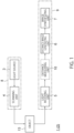
- FIG. 1 is a block diagram illustrating a schematic configuration of an image processing apparatus 1 according to a first example.
- the image processing apparatus 1 illustrated in FIG. 1 is built in, for example, a distance measuring apparatus 2. Hardware configurations of the image processing apparatus 1 and the distance measuring apparatus 2 will be described later.
- the image processing apparatus 1 illustrated in FIG. 1 includes a light source 3, a scanning unit 4, a light receiving unit 5, a distance image generating unit 6, and an image synthesizing unit 7.
- the light source 3 and the scanning unit 4 illustrated in FIG. 1 constitute a projector 8.
- the light receiving unit 5, the distance image generating unit 6, and the image synthesizing unit 7 constitute a light receiver 9.
- the light source 3 emits a plurality of light signals at predetermined time intervals. More precisely, each of the light signals emitted from the light source 3 is a light pulse signal having a predetermined pulse width.
- the light source 3 emits, for example, the light pulse signals including laser light or LED light.
- the light source 3 may include a plurality of light emitting elements, and each of the light emitting elements may emit a plurality of light signals at the same time.
- the scanning unit 4 can change at least one of the range of scanning with a light signal and the timing of the scanning with the light signal for each frame.
- the scanning unit 4 is configured using, for example, a polygon mirror, a micro electro mechanical system (MEMS) mirror, or the like.
- the scanning unit 4 changes the traveling direction of the light signal emitted from the light source 3 according to time, thereby performing the scanning with the light signal in a one-dimensional direction or a two-dimensional direction.
- Each frame is one frame of a still image acquired by scanning a field of view (FoV) of the distance measuring apparatus 2.
- the distance image generating unit 6 described later generates a distance image in units of frames.
- the scanning unit 4 can change the range of scanning with a light signal in each frame. That is, at least parts of ranges of scanning with light signals in a predetermined number of adjacent frames may be different.
- the predetermined number is two or more.
- the scanning unit 4 can change the timing of the scanning with the light signal in each frame.
- the ranges of the scanning with the light signals in the frames may be the same or different.
- the scanning unit 4 can change the scanning timing by, for example, changing the timing of emitting a light signal from the light source 3 for each frame.
- the light receiving unit 5 receives a reflected light signal obtained by irradiating an object 13 with the light signal and reflecting the light signal on the object 13.
- the light receiving unit 5 includes a plurality of light receiving elements arranged in a one-dimensional direction or a two-dimensional direction.
- the light signal received by each light receiving element is converted into, for example, a luminance signal, and a distance signal is finally generated.
- the luminance signal or the distance signal corresponding to the light signal received by each light receiving element may be referred to as a pixel.
- the distance image generated in units of frames includes a plurality of pixels, and the pixels correspond to the respective different light receiving elements.
- the object 13 is irradiated with the light signal with which the scanning is performed by the scanning unit 4, and the reflected light signal from the object 13 is received by one or more of the light receiving elements.
- the scanning unit 4 can change the range of the scanning with the light signal for each frame.
- the distance image generating unit 6 generates a distance image for each frame based on the reflected light signal received by the light receiving unit 5.
- the distance image generating unit 6 generates the distance images based on a time difference between the time when the light source 3 emits the light signal and the time when the light receiving unit 5 receives the reflected light signal.
- the image synthesizing unit 7 synthesizes the distance images of the plurality of frames to generate a high-resolution distance image.
- the distance image generating unit 6 can generate a plurality of distance images by making at least one of the range of the scanning with the light signal and the timing of the scanning with the light signal different for each frame. Therefore, the image synthesizing unit 7 can easily generate the high-resolution distance image by synthesizing the plurality of distance images.
- the beam width of the reflected light signal received by the light receiving unit 5 does not necessarily match the size of each light receiving element in the light receiving unit 5.
- the S/N ratio may decrease, the measurable distance may be limited, or the resolution of the distance image may decrease.
- the distance measuring apparatus 2 can be configured by adding a distance measurement unit 10 to the block configuration of the image processing apparatus 1 illustrated in FIG. 1 .
- the distance measurement unit 10 measures the distance to the object 13 based on the time when the reflected light signal is received by the light receiving unit 5 and the time when the light signal is emitted from the light source 3.
- FIGS. 2A and 2B are diagrams illustrating a relationship between the beam width of the reflected light signal received by the light receiving unit 5 and the size of the light receiving element 5a in the light receiving unit 5.
- a dashed line frame 11 indicates the beam width
- an alternate long and short dash line frame 12 indicates the detection range of the object 13.
- FIGS. 2A and 2B illustrate an example in which the beam width is the size of 3 pixels and the object 13 has a size of 4 pixels.
- FIG. 2A illustrates an example in which the beam width of the reflected light signal is three times the size of the light receiving element 5a.
- the intensity S of the received light at each pixel of the distance image is 1/3 of the light intensity of the reflected light signal.
- the pixel resolution is 1°.
- the effective resolution of the distance image is the same as the width of each pixel, but the measurable distance is limited because the total signal intensity is low.
- FIG. 2B illustrates an example in which the reflected light signal is received in units of three light receiving elements 5a in accordance with the beam width of the reflected light signal.
- the total signal intensity (S + N) obtained by summing the intensity S of the received light and the ambient light noise N is 4.
- the effective resolution is 3°.
- the measurable distance range can be widened, but the effective resolution is degraded more than the pixel resolution.
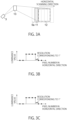
- FIG. 3A is a diagram illustrating an example in which the beam width of the reflected light signal is the same as the width of the light receiving element 5a.
- a dashed line frame 11 indicates the beam width
- an alternate long and short dash line frame 12 indicates the detection range of the object 13.
- An example is illustrated in which the beam width is the size of one pixel and the object 13 has a size of four pixels.
- FIG. 3B is a diagram illustrating luminance information of the object 13
- FIG. 3C is a diagram illustrating distance information of the object 13.
- the horizontal axis in FIGS. 3B and 3C represents a pixel number corresponding to each light receiving element 5a
- the vertical axis in FIG. 3B represents the luminance value of the object 13
- the vertical axis in FIG. 3C represents the distance to the object 13.
- FIG. 3A since the beam width of the reflected light signal matches the width of the light receiving element 5a, both the luminance information and the distance information change steeply, and edges of the luminance information and the distance information become clear.
- FIG. 4A is a diagram illustrating an example in which the beam width of the reflected light signal is the size of three pixels.
- a dashed line frame 11 indicates the beam width
- an alternate long and short dash line frame 12 indicates the detection range of the object 13.
- FIG. 4A illustrates an example in which the beam width is the size of three pixels and the object 13 has a size of four pixels.
- FIG. 4B is a diagram illustrating luminance information of the object 13
- FIG. 4C is a diagram illustrating distance information of the object 13.
- the horizontal axis in FIGS. 4B and 4C represents a pixel number corresponding to each light receiving element 5a
- the vertical axis in FIG. 4B represents the luminance value of the object 13
- the vertical axis in FIG. 4C represents the distance to the object 13.
- the position of the object 13 is originally within the range of two broken lines in each of FIGS. 4B and 4C .
- the information of the object 13 is detected also outside the broken lines.
- the object information outside the two broken lines is detection error.
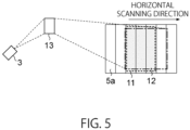
- FIG. 5 is a diagram describing a reason why the distance information includes detection error. Similarly to FIG. 4A , FIG. 5 illustrates an example in which the beam width of the reflected light signal is the size of three pixels and the object 13 has a size of four pixels.
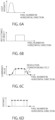
- FIG. 6A is a diagram illustrating a light intensity distribution of a light signal emitted from the light source 3, where the horizontal axis represents a pixel number in a horizontal (scanning) direction, and the vertical axis represents the light intensity.
- the light intensity distribution in FIG. 6A is known.
- FIG. 6B is a diagram illustrating the reflectance of the object 13, where the horizontal axis represents a pixel number in the horizontal (scanning) direction, and the vertical axis represents the reflectance.
- the reflectance of the object 13 is different for each object 13.
- the length between a rising point and a falling point in the horizontal axis varies depending on the size of the object 13.
- FIG. 6C is a diagram illustrating luminance information of the object 13
- FIG. 6D is a diagram illustrating distance information of the object 13.
- the horizontal axis in FIGS. 6C and 6D represents a pixel number corresponding to each light receiving element 5a
- the vertical axis in FIG. 6C represents the luminance value of the object 13
- the vertical axis in FIG. 6D represents the distance to the object 13.
- the luminance value of the object 13 is obtained by performing convolution processing on the light intensity g[n] of the light signal and the reflectance f[n] of the object 13 as expressed by the following Equation (1).
- f n ⁇ g n ⁇ f m ⁇ g n ⁇ m
- the luminance distribution of the object 13 is convolved in the scanning direction as expressed in Equation (1). Therefore, a certain luminance value is detected even in a pixel outside a pixel corresponding to the original detection position of the object 13, and an edge of the luminance information of the object 13 becomes unclear.
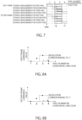
- FIG. 7 is a diagram illustrating a distance measurement sequence of a distance measuring apparatus 2 according to a comparative example.
- FIG. 7 illustrates an example in which each frame has four pixels in the scanning direction.
- a dashed line frame 11 indicates the beam width of a reflected light signal
- an alternate long and short dash line frame 12 indicates the detection range of the object 13.
- FIG. 8A is a diagram illustrating luminance information of a first frame detected by the distance measuring apparatus 2 and illustrated in FIG. 7, and FIG. 8B is a diagram illustrating luminance information of a second frame detected by the distance measuring apparatus 2 and illustrated in FIG. 7 .
- the horizontal axis represents a pixel number
- the vertical axis represents luminance information of the reflected light signal.
- a solid line indicates a light receiving position where the reflected light signal is received
- a broken line indicates a case where the object can be ideally detected.
- the object 13 is not detected in the first pixel, the object 13 is detected only in a part of the second pixel, the object 13 is detected in the entire region of the third pixel, and the object 13 is not detected in the fourth pixel. Therefore, as illustrated in FIGS. 8A and 8B , the luminance information becomes an intermediate level in the second pixel, the luminance information becomes the maximum level in the third pixel, and the luminance information becomes the minimum level in the first and fourth pixels.
- FIG. 9A is a diagram illustrating distance information of the object 13 in the first frame detected by the distance measuring apparatus 2 and illustrated in FIG. 7
- FIG. 9B is a diagram illustrating distance information of the object 13 in the second frame detected by the distance measuring apparatus 2 and illustrated in FIG. 7
- the horizontal axis represents a pixel number
- the vertical axis represents the distance to the object 13.
- a solid line indicates a light receiving position where the reflected light signal is received
- a broken line indicates a case where the object can be ideally detected.
- the resolution corresponds to 1°.
- FIG. 10 is a diagram illustrating a distance measurement sequence of the image processing apparatus 1 and the distance measuring apparatus 2 according to the present example.
- FIG. 10 illustrates an example in which each frame has four pixels in the scanning direction, similarly to FIG. 7 .
- a dashed line frame 11 indicates the beam width of the reflected light signal
- an alternate long and short dash line frame 12 indicates the detection range of the object 13.
- FIG. 11A is a diagram illustrating luminance information of the first frame detected by the distance measuring apparatus 2 illustrated in FIG. 1
- FIG. 11B is a diagram illustrating luminance information of the second frame detected by the distance measuring apparatus 2 illustrated in FIG. 1
- FIG. 11C is a diagram in which the luminance information illustrated in FIG. 11A is combined with the luminance information illustrated in 11B.
- the horizontal axis represents a pixel number
- the vertical axis represents luminance information of the reflected light signal.
- a solid line indicates a light receiving position where the reflected light signal is received
- a broken line indicates a case where the object can be ideally detected.
- the first frame illustrated in FIG. 10 is similar to the first frame illustrated in FIG. 7 , and the luminance information of the reflected light signal of the first frame illustrated in FIG. 11A is the same as the luminance information illustrated in FIG. 8A .
- a light signal is emitted from the light source 3 with a delay of a 1/2 pixel from the first frame. Therefore, as illustrated in FIG. 11B , the luminance information of the reflected light signal of the second frame is detected with a delay of a 1/2 pixel from the luminance information illustrated in FIG. 11A .
- the scanning unit 4 performs scanning with a light signal at a constant speed, when the light signal is emitted from the light source 3 with a delay of a 1/2 pixel, the light signal is emitted to a position shifted by a 1/2 pixel with respect to the object 13, and the reflected light signal is received at a position shifted by a 1/2 pixel with respect to the light receiving unit 5.
- luminance information as illustrated in FIG. 11C is obtained.
- the resolution of the luminance information in FIG. 11C is twice that of the luminance information in FIGS. 11A and 11B , and the luminance information can be detected more accurately.
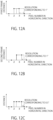
- FIG. 12A is a diagram illustrating distance information of the object 13 in a first frame detected by the image processing apparatus 1 and the distance measuring apparatus 2 illustrated in FIG. 10
- FIG. 12B is a diagram illustrating distance information of the object 13 in a second frame detected by the image processing apparatus 1 and the distance measuring apparatus 2 illustrated in FIG. 10
- FIG. 12C is a diagram in which the distance information illustrated in FIG. 12A is combined with the distance information illustrated in 12B.
- Each plot in FIGS. 12A to 12C indicates a detection position where the distance information is detected.
- the distance information of the object 13 is detected with a delay of a 1/2 pixel from the first frame.
- the distance to a portion of the object 13 present near the edge of the object 13 can be accurately detected, and the distance resolution can be improved.
- the scanning unit 4 illustrated in FIG. 1 can change at least one of the range of scanning with a light signal and the timing of the scanning with the light signal for each frame.
- a plurality of specific examples can be considered as a method in which the scanning unit 4 performs scanning with a light signal.
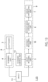
- FIG. 13 is a block diagram of an image processing apparatus 1 according to a first specific example of FIG. 1 .
- the light source 3 and the scanning unit 4 illustrated in FIG. 13 constitute a projector 8.
- the light receiving unit 5, the distance measurement unit 10, the distance image generating unit 6, and the image synthesizing unit 7 in FIG. 13 constitute a light receiver 9.
- the image processing apparatus 1 illustrated in FIG. 13 includes a scanning control unit 15 in addition to the configuration illustrated in FIG. 1 .
- the scanning control unit 15 controls the scanning unit 4.
- the scanning control unit 15 switches and controls the light emission direction of the scanning unit 4.
- the scanning unit 4 includes a mirror member that switches the traveling direction of a light signal emitted from the light source 3, such as a polygon mirror or a MEMS mirror.
- the scanning control unit 15 may change the traveling direction of the light signal emitted from the scanning unit 4 for each frame by not only performing control to rotate the mirror surface of the mirror member but also rotating the mirror member itself within a predetermined angle range.
- the scanning control unit 15 may switch and control the light emission direction of a housing unit in which the light source 3 is built. As a result, the traveling direction of the light signal emitted from the light source 3 can be changed, and the range of scanning with the light signal emitted from the scanning unit 4 can be changed for each frame.
- the scanning control unit 15 may variably control the speed at which the scanning unit 4 switches the traveling direction of the light signal. That is, the scanning control unit 15 can variably control the resolution of the distance image by switching and controlling the speed of the scanning with the light signal by the scanning unit 4.
- FIG. 14 is a block diagram of an image processing apparatus 1 according to a second specific example of FIG. 1 .
- the image processing apparatus 1 illustrated in FIG. 14 includes a timing control unit 16 in addition to the configuration illustrated in FIG. 13 .
- the timing control unit 16 controls an emission start timing at which the light source 3 starts emitting a light signal.
- the scanning unit 4 switches the timing of scanning with the light signal for each frame based on the emission start timing at which the light source 3 starts emitting the light signal.
- the timing control unit 16 variably controls the emission start timing of the light signal for each frame without changing the emission interval of the light signal emitted from the light source 3.
- the light source 3 emits a plurality of light signals at the same emission interval starting from different emission start times.
- the image synthesizing unit 7 synthesizes distance images generated in each of the n frames.
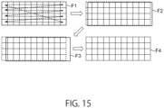
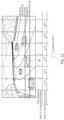
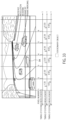
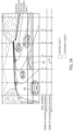
- FIG. 15 is a diagram schematically illustrating an example in which the scanning unit 4 changes at least one of the range of scanning with a light signal and the timing of the scanning with the light signal for each frame.
- the scanning unit 4 performs scanning with the light signal in the horizontal direction, and when the scanning of one horizontal line is completed, the operation of scanning the next horizontal line from left to right with the light signal is repeated for all horizontal lines.
- Each square in the frame F1 indicates a pixel received by each light receiving element 5a.
- the light source 3 When a distance image of the frame F1 is generated, the light source 3 emits a light signal with a delay of a 1/3 pixel, and the reflected light signal from the object 13 is received by the light receiving unit 5 to generate a distance image in the next frame F2.
- a light signal is emitted from the light source 3 with a delay of a 2/3 pixel, and the reflected light signal from the object 13 is received by the light receiving unit 5 to generate a distance image in the next frame F3.
- a light signal is emitted from the light source 3 at the same timing as the frame F1 to generate a distance image in the next frame F4.
- the image synthesizing unit 7 synthesizes the three distance images of the frames F1 to F3 to generate a high-resolution distance image.
- FIG. 15 illustrates an example in which the three distance images of the frames F1 to F3 are synthesized, but the number of distance images to be synthesized is arbitrary.
- FIG. 16 is a flowchart illustrating a first example of a processing operation of the image processing apparatus 1 and the distance measuring apparatus 2 according to the first example.
- a distance image G1 is generated by scanning with a light signal without shifting the scanning range (step S1).
- FIG. 17A is a diagram schematically illustrating the distance image G1 generated in step S1 illustrated in FIG. 16 .
- FIG. 17A illustrates an example of a distance image G1 having 6 pixels in the horizontal direction and 4 pixels in the vertical direction.
- FIG. 17B is a diagram schematically illustrating the distance image G2 generated in step S2 illustrated in FIG. 16 .
- FIG. 17C is a diagram schematically illustrating the distance image G3 generated in step S3 illustrated in FIG. 16 .
- the distance images G1 and G2 for the two frames it is possible to generate the high-resolution distance image G3 in which the resolution in the horizontal direction is doubled.
- FIG. 18 is a flowchart illustrating a second example of a processing operation of the image processing apparatus 1 and the distance measuring apparatus 2 according to the first example.
- a distance image is generated by scanning with a light signal in a reference scanning range (step S11).
- FIG. 19A is a diagram schematically illustrating the distance image G1 generated in step S11 illustrated in FIG. 18 .
- FIG. 19B is a diagram schematically illustrating the distance image G2 generated in step S12 illustrated in FIG. 18 .
- FIG. 19C is a diagram schematically illustrating the distance image generated in step S13 illustrated in FIG. 18 . As illustrated in FIG. 19C , by synthesizing the distance images for the two frames, the resolution in the vertical direction can be doubled.
- a plurality of distance images generated by changing at least one of the range of scanning with a light signal and the timing of the scanning with the light signal for each frame are synthesized to generate a high-resolution distance image. This makes it possible to increase the resolution of the distance image with a simple configuration without providing a lens or the like for reducing the beam width of the light signal emitted from the light source 3.
- FIG. 20 is a block diagram illustrating a schematic configuration of an image processing apparatus 1 according to a second example.
- the image processing apparatus 1 illustrated in FIG. 20 is obtained by adding a blur elimination processing unit 17 to the configuration illustrated in FIG. 14 .
- the blur elimination processing unit 17 performs processing of making a high-resolution distance image generated by the image synthesizing unit 7 clearer. Specifically, the blur elimination processing unit 17 performs processing of eliminating a blur in an edge portion of a distance and luminance image and sharpening the edge portion.
- FIG. 21 is a block diagram of the image processing apparatus 1 illustrated in FIG. 20 , in which the blur elimination processing unit 17 is further embodied.
- the blur elimination processing unit 17 illustrated in FIG. 21 includes a deconvolution processing unit 18 and an edge sharpening unit 19.
- the deconvolution processing unit 18 performs deconvolution processing on the high-resolution distance image generated by the image synthesizing unit 7 using a light intensity distribution of a light signal emitted from the light source 3 to generate the reflectance of the object 13.
- the edge enhancing unit 19 enhances an edge of the high-resolution distance image generated by the image synthesizing unit 7 based on the reflectance of the object 13 generated by the deconvolution processing unit 18.
- FIG. 22 is a diagram describing a processing operation of the blur elimination processing unit 17.
- the distance image generating unit 6 generates luminance information and distance information based on a light signal received by the light receiving unit 5.
- the luminance information generated by the distance image generating unit 6 is represented by, for example, a waveform w1
- the distance information is represented by, for example, a waveform w2.
- the waveforms w1 and w2 when the beam width of the reflected light signal is wider than the width of the light receiving element 5a, the luminance information and the distance information have values including errors.
- the light intensity g[n] of the light signal emitted from the light source 3 is known. Therefore, the deconvolution processing unit 18 can generate the reflectance of the object 13 by performing the deconvolution processing of g[n] on the luminance information.
- the reflectance of the object 13 is represented by, for example, a waveform w3 illustrated in FIG. 22 .
- the reflectance of the object 13 generated by the deconvolution processing unit 18 is information not including an error.
- the light intensity g[n] is obtained by measuring the light intensity in advance. Alternatively, the light intensity g[n] can also be obtained by acquiring an intensity distribution of laser light at each distance measurement using the light receiving elements provided in the projector.
- the edge sharpening unit 19 corrects the luminance information generated by the distance image generating unit 6 based on the reflectance of the object 13 generated by the deconvolution processing unit 18, and also corrects the distance information. As a result, as indicated by waveforms w4 and w5, clear luminance information and distance information that have clear edges can be obtained.
- the deconvolution processing is performed on the luminance information included in the distance image generated by the distance image generating unit 6, but as illustrated in FIG. 21 , the deconvolution processing may be performed on the luminance information included in the high-resolution distance image generated by the image synthesizing unit 7.
- the edge enhancing unit 19 sets a threshold for a luminance signal corresponding to the reflected light signal received by the light receiving unit 5 based on the reflectance of the object 13 generated by the deconvolution processing unit 18, binarizes the luminance signal based on the threshold, and corrects the high-resolution distance image generated by the image synthesizing unit 7 based on the binarized luminance value.
- the edge enhancing unit 19 estimates a luminance value corresponding to the reflected light signal received by the light receiving unit 5 based on the reflectance of the object 13 generated by the deconvolution processing unit 18, and corrects the high-resolution distance image generated by the image synthesizing unit 7 based on the luminance value.
- the reflectance of the object 13 is generated by performing the deconvolution processing of the light intensity of the light signal on the luminance information based on the light signal received by the light receiving unit 5, and the luminance information and the distance information are corrected based on the generated reflectance of the object 13.
- the luminance information and the distance information are corrected based on the generated reflectance of the object 13.
- FIG. 23 is a block diagram illustrating a schematic configuration of an image processing apparatus 1 according to a third example.
- the image processing apparatus 1 illustrated in FIG. 23 includes a feature object recognizing unit 20 in addition to the configuration illustrated in FIG. 20 .
- the feature object recognizing unit 20 recognizes a feature object included in a distance image generated by the distance image generating unit 6.
- the feature object is, for example, a stationary object that satisfies a predetermined condition.
- the predetermined condition is that the stationary object is not present before a predetermined period, for example.
- Specific examples of the feature object include a depression on a road, an obstacle placed on a road, and the like.
- the image synthesizing unit 7 generates a high-resolution distance image at a first frame rate for the feature object, and generates a distance image at a second frame rate higher than the first frame rate without changing the resolution for a region other than the feature object.
- the feature object recognizing unit 20 may recognize a moving object.
- the image synthesizing unit 7 generates a distance image at the second frame rate without changing the resolution for the moving object recognized by the feature object recognizing unit 20.
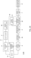
- FIG. 24 is a block diagram illustrating the image processing apparatus 1 illustrated FIG. 23 , in which the feature object recognizing unit 20 is further embodied.
- the feature object recognizing unit 20 illustrated in FIG. 24 includes a frame memory 21 and an interframe difference detecting unit 22.
- the frame memory 21 stores a distance image for at least one frame.
- the interframe difference detecting unit 22 detects a difference between distance images of a plurality of frames and recognizes a feature object.
- the interframe difference detecting unit 22 may include a first recognizing unit and a second recognizing unit.
- the first recognizing unit takes a difference between a distance image generated by the distance image generating unit 6 and a distance image generated before a predetermined period, thereby recognizing a feature object that is not present before the predetermined period and is stationary.
- the second recognizing unit recognizes the moving object 13 by taking a difference between a plurality of distance images generated most recently by the distance image generating unit 6.
- the image synthesizing unit 7 generates a high-resolution distance image at a first frame rate in a region including the feature object based on a result of the recognition by the first recognizing unit, and generates a distance image at a second frame rate higher than the first frame rate in a region not including the feature object.
- the image synthesizing unit 7 generates a high-resolution distance image at the first frame rate in a region including the feature object recognized by the first recognizing unit, and generates a distance image at the second frame rate in a region including the moving object recognized by the second recognizing unit.
- FIG. 25 is a flowchart illustrating a first example of a processing operation of the image processing apparatus 1 and a distance measuring apparatus 2 according to the third example.
- a distance image is generated by scanning with a light signal in a predetermined reference scanning range (step S21).
- FIG. 26A is a diagram schematically illustrating the distance image G1 generated in step S21 illustrated in FIG. 25 .
- FIG. 26B is a diagram schematically illustrating the distance image G2 generated in step S22 illustrated in FIG. 25 .
- the feature object recognizing unit 20 recognizes the feature object and specifies the position of the feature object included in the distance image (step S23).
- the specified feature object is, for example, a stationary object.
- the image synthesizing unit 7 synthesizes feature object images PG of the first and second frames to generate a high-resolution feature object image PG (step S24).
- the image synthesizing unit 7 generates a distance image at a normal frame rate without synthesizing images for a region other than the feature object (step S25).
- FIG. 26C is a diagram schematically illustrating a distance image G3 of an odd-numbered frame finally generated by the processing described with reference to FIG. 25
- FIG. 26D is a diagram schematically illustrating a distance image G4 of an even-numbered frame.
- FIGS. 26C and 26D only regions of the feature object that are included in the distance images are generated as high-resolution and low-frame-rate feature images PG, and regions other than the regions of the feature object are generated as low-resolution and high-frame-rate range images G3 and G4.
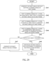
- FIG. 27 is a flowchart illustrating a second example of a processing operation of the image processing apparatus 1 and the distance measuring apparatus 2 according to the third example.
- a distance image is generated by scanning with a light signal in the predetermined reference scanning range (step S31).
- FIG. 28A is a diagram schematically illustrating the distance image G1 generated in step S31 illustrated in FIG. 27 .
- the position of the feature object included in the distance image is specified (step S32).
- the specified feature object is, for example, a stationary object.
- the light source 3 emits a light signal while the scanning range is shifted (delayed) by a 1/2 pixel in the second frame, and a reflected light signal from the object 13 is received to generate a feature object image PG (step S33).
- FIG. 28B is a diagram schematically illustrating the feature object image PG generated in step S33 illustrated in FIG. 27 .
- the feature object image PG of the first frame and the feature object image PG of the second frame are synthesized to generate a high-resolution feature object image PG (step S34).
- the light source 3 emits a light signal in the same scanning range as that in the first frame or at the same scanning timing as that in the first frame for the second frame, a reflected light signal from the object 13 is received, and a distance image is generated for each frame (step S35).
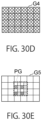
- FIG. 28C is a diagram schematically illustrating a distance image G3 of an odd-numbered frame finally generated by the processing described with reference to FIG. 27
- FIG. 28D is a diagram schematically illustrating a distance image G4 of an even-numbered frame.
- high-definition and low-frame-rate feature images PG are generated in regions of the feature object
- high-frame-rate distance images G3 and G4 are generated in regions other than the feature object.
- FIG. 29 is a flowchart illustrating a third example of a processing operation of the image processing apparatus 1 and the distance measuring apparatus 2 according to the third example.
- a distance image is generated by scanning with a light signal in the predetermined reference scanning range (step S41).
- FIG. 30A is a diagram schematically illustrating the distance image G1 generated in step S41 illustrated in FIG. 29 .
- FIG. 30B is a diagram schematically illustrating the distance image G2 generated in step S42 illustrated in FIG. 29 .
- FIG. 30C is a diagram schematically illustrating the distance image G3 generated in step S43 illustrated in FIG. 29 .
- FIG. 30D is a diagram schematically illustrating the distance image G4 generated in step S44 illustrated in FIG. 29 .
- the position of the feature object included in the distance image is specified (step S45).
- the feature object images PG of the first to fourth frames are synthesized to generate a high-resolution feature object image PG.
- a distance image G5 is generated for each frame (step S46).
- FIG. 30E is a diagram schematically illustrating the distance image G5 finally generated by the image processing apparatus 1 and the distance measuring apparatus 2 in the processing illustrated in FIG. 29 .
- a high-definition and low-frame-rate feature image PG is generated in the region of the feature object, and a high-frame-rate distance image G5 is generated in the region other than the feature object.
- FIGS. 31 to 34 are diagrams schematically illustrating a state in which an infrastructure is monitored using the image processing apparatus 1 and the distance measuring apparatus 2 according to the third example. More specifically, FIGS. 31 to 34 illustrate a state of monitoring whether or not a depression 34 has occurred on a road.
- the image processing apparatus 1 and the distance measuring apparatus 2 cause the scanning unit 4 to perform scanning with a light signal emitted from the light source 3 to generate a distance image.
- the feature object may be recognized first, and the scanning range may be shifted by a 1/2 pixel for each frame only for the feature object.
- FIG. 31 illustrates an example in which the depression 34 has occurred on the road.
- the range and timing of scanning with the light signal by the scanning unit 4 are the same in the first and second frames.
- FIG. 32 illustrates an example in which the depression 34 on the road is recognized as a feature object and a second frame is scanned with a light signal shifted by a 1/2 pixel from a first frame.
- the image synthesizing unit 7 synthesizes distance images of the first and second frames to generate a high-resolution distance image.
- FIG. 32 illustrates an example in which a high-resolution distance image is generated over the entire frame.
- the depression 34 on the road is recognized as a feature object
- a second frame is scanned with a light signal shifted by a 1/3 pixel from a first frame
- a third frame is scanned with a light signal shifted by a 2/3 pixel from the first frame.
- the image synthesizing unit 7 synthesizes feature object images PG of the first to third frames to generate a feature object image PG having a higher resolution than that of the feature object image illustrated in FIG. 32 .
- FIG. 33 illustrates an example in which a high-resolution distance image is generated over the entire frame.
- the depression 34 on the road is recognized as a feature object
- a light signal is emitted while being shifted by a 1/2 pixel for a region of the depression 34 on the road
- a reflected light signal from the depression 34 is received to generate a feature object image PG
- feature object images PG of a first frame and a second frame are synthesized to generate a high-resolution feature object image PG.
- a distance image is generated at a high frame rate for each frame.
- the above-described second recognizing unit 24 may recognize the moving object and generate the distance image at the high frame rate.
- the feature object recognizing unit 20 can recognize a feature object that is not present before the predetermined period and is stationary by taking a difference between a newly generated distance image and a distance image generated before the predetermined period. Furthermore, the feature object recognizing unit 20 can recognize the moving object 13 by taking a difference between a plurality of distance images generated most recently.
- the image synthesizing unit 7 can synthesize feature images PG in a plurality of frames to generate a high-resolution feature object image PG for a feature object that is not present before the predetermined period and is stationary.
- the moving object since a distance image is generated for each frame for a moving object, the moving object can be tracked with high accuracy.
- At least a part of the image processing apparatus 1 and the distance measuring apparatus 2 according to each of the first to third examples described above may be configured by hardware or software.
- FIG. 35 is a block diagram in a case where the image processing apparatus 1 and the distance measuring apparatus 2 according to each of the first to third examples are configured as hardware.
- Each of the image processing apparatus 1 and the distance measuring apparatus 2 illustrated in FIG. 35 includes a light source 3, a scanning device 31, a light receiving device 32, and a signal processing processor 33.
- the light source 3 may be a laser light source or an LED light source.
- the light source 3 may include a plurality of laser light sources or a plurality of LED light sources.
- the scanning device 31 corresponds to the scanning unit 4 according to the first to third examples.
- the scanning device 31 has a function of performing scanning with a light signal in a predetermined scanning range, such as a polygon mirror or a MEMS mirror.
- the light receiving device 32 corresponds to the light receiving unit 5 according to the first to third examples.
- the light receiving device 32 may include a plurality of light receiving elements 5a.
- the signal processing processor 33 may be a semiconductor chip such as a central processing unit (CPU), a field programmable gate array (FPGA), or a digital signal processor (DSP), or may be a computer device such as a personal computer (PC), a workstation, or a server.
- the signal processing processor 33 also functions as the scanning control unit 15 and the timing control unit 16 according to the first to third examples. Furthermore, the signal processing processor 33 may have the function of the distance measurement unit 10.
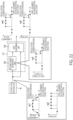
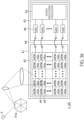
- FIG. 36 is a block diagram illustrating a specific hardware configuration of the image processing apparatus 1 and the distance measuring apparatus 2 according to each of the first to third examples.
- a polygon mirror 31a is used as an example of the scanning device 31.
- the image processing apparatus 1 and the distance measuring apparatus 2 in FIG. 36 use a silicon in package (SIP) in which the light receiving device 32 and the signal processing processor 33 are incorporated in the same package.
- SIP silicon in package
- a first die 42 and a second die 43 are provided on a support substrate 41.
- Each light receiving device 32 includes a silicon photomultiplier (SiPM) 44 and an active quenching circuit (AQs) 45.
- SiPM 44 has one or more avalanche photodiodes (APDs). Note that a passive quenching circuit may be provided instead of the active quenching circuit 45.
- ADCs 46 that convert a light signal received by each SiPM 44 into digital pixel data and the signal processing processor 33 are provided.
- a pad 47 on the first die 42 and a corresponding pad 48 on the second die 43 are connected to each other by a bonding wire 49.
- components other than the light source 3 and the scanning device 31 can be constituted by one semiconductor chip, miniaturization and low power consumption can be achieved.
Landscapes
- Engineering & Computer Science (AREA)
- Physics & Mathematics (AREA)
- General Physics & Mathematics (AREA)
- Computer Networks & Wireless Communication (AREA)
- Radar, Positioning & Navigation (AREA)
- Remote Sensing (AREA)
- Theoretical Computer Science (AREA)
- Electromagnetism (AREA)
- Multimedia (AREA)
- Computer Vision & Pattern Recognition (AREA)
- Optical Radar Systems And Details Thereof (AREA)
Applications Claiming Priority (1)
| Application Number | Priority Date | Filing Date | Title |
|---|---|---|---|
| JP2022032146A JP7680977B2 (ja) | 2022-03-02 | 2022-03-02 | 画像処理装置、測距装置、及び画像処理方法 |
Publications (3)
| Publication Number | Publication Date |
|---|---|
| EP4239366A2 true EP4239366A2 (fr) | 2023-09-06 |
| EP4239366A3 EP4239366A3 (fr) | 2023-10-18 |
| EP4239366B1 EP4239366B1 (fr) | 2025-10-22 |
Family
ID=83318754
Family Applications (1)
| Application Number | Title | Priority Date | Filing Date |
|---|---|---|---|
| EP22193424.3A Active EP4239366B1 (fr) | 2022-03-02 | 2022-09-01 | Appareil de traitement d'image, appareil de mesure de distance et procédé de traitement d'image |
Country Status (3)
| Country | Link |
|---|---|
| US (1) | US12367552B2 (fr) |
| EP (1) | EP4239366B1 (fr) |
| JP (1) | JP7680977B2 (fr) |
Family Cites Families (14)
| Publication number | Priority date | Publication date | Assignee | Title |
|---|---|---|---|---|
| JP5448617B2 (ja) * | 2008-08-19 | 2014-03-19 | パナソニック株式会社 | 距離推定装置、距離推定方法、プログラム、集積回路およびカメラ |
| CN107710015B (zh) * | 2015-07-03 | 2021-08-24 | 新唐科技日本株式会社 | 距离测量装置以及距离图像合成方法 |
| EP4293319A3 (fr) * | 2017-01-05 | 2024-03-20 | Fraunhofer-Gesellschaft zur Förderung der angewandten Forschung e.V. | Génération et utilisation de cartes hd |
| WO2018179649A1 (fr) * | 2017-03-28 | 2018-10-04 | 株式会社日立産機システム | Système de création de carte et système de robot |
| US10983213B2 (en) * | 2017-03-29 | 2021-04-20 | Luminar Holdco, Llc | Non-uniform separation of detector array elements in a lidar system |
| JP7069927B2 (ja) * | 2018-03-26 | 2022-05-18 | 株式会社デンソー | 物体認識装置、及び物体認識方法 |
| US11609328B2 (en) * | 2018-05-23 | 2023-03-21 | Massachusetts Institute Of Technology | Methods and apparatus for improved imaging through scattering media |
| WO2020110801A1 (fr) | 2018-11-30 | 2020-06-04 | 株式会社小糸製作所 | Capteur de télémétrie, feu de véhicule et procédé de télémétrie |
| JPWO2021019906A1 (fr) * | 2019-07-26 | 2021-02-04 | ||
| CN116755107A (zh) | 2020-01-23 | 2023-09-15 | 华为技术有限公司 | 一种飞行时间tof传感模组及电子设备 |
| CN116034289A (zh) * | 2020-05-13 | 2023-04-28 | 卢米诺有限责任公司 | 具有高分辨率扫描图案的激光雷达系统 |
| WO2021234333A1 (fr) * | 2020-05-19 | 2021-11-25 | Cambridge Mechatronics Limited | Système de capteur de temps de vol |
| JP2022018229A (ja) * | 2020-07-15 | 2022-01-27 | 富士通株式会社 | 距離測定装置、距離測定方法及びプログラム |
| JP7423485B2 (ja) * | 2020-09-18 | 2024-01-29 | 株式会社東芝 | 距離計測装置 |
-
2022
- 2022-03-02 JP JP2022032146A patent/JP7680977B2/ja active Active
- 2022-09-01 EP EP22193424.3A patent/EP4239366B1/fr active Active
- 2022-09-08 US US17/930,599 patent/US12367552B2/en active Active
Also Published As
| Publication number | Publication date |
|---|---|
| EP4239366A3 (fr) | 2023-10-18 |
| US12367552B2 (en) | 2025-07-22 |
| EP4239366B1 (fr) | 2025-10-22 |
| JP2023128077A (ja) | 2023-09-14 |
| JP7680977B2 (ja) | 2025-05-21 |
| US20230281771A1 (en) | 2023-09-07 |
Similar Documents
| Publication | Publication Date | Title |
|---|---|---|
| JP7347585B2 (ja) | 距離測定装置 | |
| JP7238343B2 (ja) | 距離測定装置及び距離測定方法 | |
| US11402508B2 (en) | Distance-measuring system and distance-measuring method | |
| EP3457170B1 (fr) | Dispositif de mesure de distance | |
| CN102947726B (zh) | 扫描3d成像仪 | |
| CN111788495B (zh) | 光检测装置、光检测方法以及激光雷达装置 | |
| WO2018056199A1 (fr) | Système de mesure de distance, procédé de mesure de distance et dispositif d'enregistrement de programme | |
| CN110389334B (zh) | 图像处理装置、图像处理方法以及距离测量系统 | |
| US7079298B2 (en) | Optical deflector | |
| EP3540497B1 (fr) | Appareil de balayage optique, appareil de projection d'images et objet mobile | |
| JP7711717B2 (ja) | 測距装置およびその制御方法、並びに、測距システム | |
| JP2022050239A (ja) | 距離計測装置、及び距離計測方法 | |
| WO2020187677A1 (fr) | Dispositif lidar pour véhicule et procédé d'augmentation de portée de détection d'un dispositif lidar correspondant | |
| WO2022154073A1 (fr) | Dispositif d'imagerie télémétrique et procédé d'imagerie télémétrique | |
| CN112540361A (zh) | 光检测装置以及电子装置 | |
| EP4239366A2 (fr) | Appareil de traitement d'image, appareil de mesure de distance et procédé de traitement d'image | |
| JP7434128B2 (ja) | 距離計測装置 | |
| KR102178800B1 (ko) | 제어 장치, 화상 투영 장치, 및 제어 방법 | |
| CN111308447A (zh) | 用于控制lidar系统内的系统定时的装置和方法 | |
| JP2020193957A (ja) | 測距異常を補正する距離画像生成装置 | |
| US20210088660A1 (en) | Distance measuring device and distance measuring method | |
| US20180003938A1 (en) | Scanning microscope | |
| JPWO2012108032A1 (ja) | 画像表示装置、及び光軸ずれ検出方法 | |
| US20260023181A1 (en) | Ranging apparatus | |
| JP2025187828A (ja) | 距離画像生成装置および機器 |
Legal Events
| Date | Code | Title | Description |
|---|---|---|---|
| PUAI | Public reference made under article 153(3) epc to a published international application that has entered the european phase |
Free format text: ORIGINAL CODE: 0009012 |
|
| STAA | Information on the status of an ep patent application or granted ep patent |
Free format text: STATUS: REQUEST FOR EXAMINATION WAS MADE |
|
| 17P | Request for examination filed |
Effective date: 20220901 |
|
| AK | Designated contracting states |
Kind code of ref document: A2 Designated state(s): AL AT BE BG CH CY CZ DE DK EE ES FI FR GB GR HR HU IE IS IT LI LT LU LV MC MK MT NL NO PL PT RO RS SE SI SK SM TR |
|
| PUAL | Search report despatched |
Free format text: ORIGINAL CODE: 0009013 |
|
| AK | Designated contracting states |
Kind code of ref document: A3 Designated state(s): AL AT BE BG CH CY CZ DE DK EE ES FI FR GB GR HR HU IE IS IT LI LT LU LV MC MK MT NL NO PL PT RO RS SE SI SK SM TR |
|
| RIC1 | Information provided on ipc code assigned before grant |
Ipc: G01S 17/89 20200101ALI20230911BHEP Ipc: G01S 17/42 20060101ALI20230911BHEP Ipc: G01S 7/481 20060101AFI20230911BHEP |
|
| GRAP | Despatch of communication of intention to grant a patent |
Free format text: ORIGINAL CODE: EPIDOSNIGR1 |
|
| STAA | Information on the status of an ep patent application or granted ep patent |
Free format text: STATUS: GRANT OF PATENT IS INTENDED |
|
| INTG | Intention to grant announced |
Effective date: 20250519 |
|
| GRAS | Grant fee paid |
Free format text: ORIGINAL CODE: EPIDOSNIGR3 |
|
| GRAA | (expected) grant |
Free format text: ORIGINAL CODE: 0009210 |
|
| STAA | Information on the status of an ep patent application or granted ep patent |
Free format text: STATUS: THE PATENT HAS BEEN GRANTED |
|
| AK | Designated contracting states |
Kind code of ref document: B1 Designated state(s): AL AT BE BG CH CY CZ DE DK EE ES FI FR GB GR HR HU IE IS IT LI LT LU LV MC MK MT NL NO PL PT RO RS SE SI SK SM TR |
|
| REG | Reference to a national code |
Ref country code: CH Ref legal event code: F10 Free format text: ST27 STATUS EVENT CODE: U-0-0-F10-F00 (AS PROVIDED BY THE NATIONAL OFFICE) Effective date: 20251022 Ref country code: GB Ref legal event code: FG4D |
|
| REG | Reference to a national code |
Ref country code: DE Ref legal event code: R096 Ref document number: 602022023373 Country of ref document: DE |
|
| REG | Reference to a national code |
Ref country code: IE Ref legal event code: FG4D |