EP4239350A1 - Insulation resistance measurement device - Google Patents
Insulation resistance measurement device Download PDFInfo
- Publication number
- EP4239350A1 EP4239350A1 EP22893197.8A EP22893197A EP4239350A1 EP 4239350 A1 EP4239350 A1 EP 4239350A1 EP 22893197 A EP22893197 A EP 22893197A EP 4239350 A1 EP4239350 A1 EP 4239350A1
- Authority
- EP
- European Patent Office
- Prior art keywords
- voltage
- insulation
- resistor
- measuring device
- positive
- Prior art date
- Legal status (The legal status is an assumption and is not a legal conclusion. Google has not performed a legal analysis and makes no representation as to the accuracy of the status listed.)
- Granted
Links
Images


Classifications
-
- G—PHYSICS
- G01—MEASURING; TESTING
- G01R—MEASURING ELECTRIC VARIABLES; MEASURING MAGNETIC VARIABLES
- G01R27/00—Arrangements for measuring resistance, reactance, impedance, or electric characteristics derived therefrom
- G01R27/02—Measuring real or complex resistance, reactance, impedance, or other two-pole characteristics derived therefrom, e.g. time constant
- G01R27/025—Measuring very high resistances, e.g. isolation resistances, i.e. megohm-meters
-
- G—PHYSICS
- G01—MEASURING; TESTING
- G01R—MEASURING ELECTRIC VARIABLES; MEASURING MAGNETIC VARIABLES
- G01R31/00—Arrangements for testing electric properties; Arrangements for locating electric faults; Arrangements for electrical testing characterised by what is being tested not provided for elsewhere
- G01R31/36—Arrangements for testing, measuring or monitoring the electrical condition of accumulators or electric batteries, e.g. capacity or state of charge [SoC]
- G01R31/389—Measuring internal impedance, internal conductance or related variables
-
- B—PERFORMING OPERATIONS; TRANSPORTING
- B60—VEHICLES IN GENERAL
- B60L—PROPULSION OF ELECTRICALLY-PROPELLED VEHICLES; SUPPLYING ELECTRIC POWER FOR AUXILIARY EQUIPMENT OF ELECTRICALLY-PROPELLED VEHICLES; ELECTRODYNAMIC BRAKE SYSTEMS FOR VEHICLES IN GENERAL; MAGNETIC SUSPENSION OR LEVITATION FOR VEHICLES; MONITORING OPERATING VARIABLES OF ELECTRICALLY-PROPELLED VEHICLES; ELECTRIC SAFETY DEVICES FOR ELECTRICALLY-PROPELLED VEHICLES
- B60L58/00—Methods or circuit arrangements for monitoring or controlling batteries or fuel cells, specially adapted for electric vehicles
- B60L58/10—Methods or circuit arrangements for monitoring or controlling batteries or fuel cells, specially adapted for electric vehicles for monitoring or controlling batteries
-
- G—PHYSICS
- G01—MEASURING; TESTING
- G01R—MEASURING ELECTRIC VARIABLES; MEASURING MAGNETIC VARIABLES
- G01R27/00—Arrangements for measuring resistance, reactance, impedance, or electric characteristics derived therefrom
- G01R27/02—Measuring real or complex resistance, reactance, impedance, or other two-pole characteristics derived therefrom, e.g. time constant
- G01R27/08—Measuring resistance by measuring both voltage and current
-
- G—PHYSICS
- G01—MEASURING; TESTING
- G01R—MEASURING ELECTRIC VARIABLES; MEASURING MAGNETIC VARIABLES
- G01R31/00—Arrangements for testing electric properties; Arrangements for locating electric faults; Arrangements for electrical testing characterised by what is being tested not provided for elsewhere
- G01R31/005—Testing of electric installations on transport means
- G01R31/006—Testing of electric installations on transport means on road vehicles, e.g. automobiles or trucks
-
- G—PHYSICS
- G01—MEASURING; TESTING
- G01R—MEASURING ELECTRIC VARIABLES; MEASURING MAGNETIC VARIABLES
- G01R31/00—Arrangements for testing electric properties; Arrangements for locating electric faults; Arrangements for electrical testing characterised by what is being tested not provided for elsewhere
- G01R31/36—Arrangements for testing, measuring or monitoring the electrical condition of accumulators or electric batteries, e.g. capacity or state of charge [SoC]
-
- G—PHYSICS
- G01—MEASURING; TESTING
- G01R—MEASURING ELECTRIC VARIABLES; MEASURING MAGNETIC VARIABLES
- G01R31/00—Arrangements for testing electric properties; Arrangements for locating electric faults; Arrangements for electrical testing characterised by what is being tested not provided for elsewhere
- G01R31/36—Arrangements for testing, measuring or monitoring the electrical condition of accumulators or electric batteries, e.g. capacity or state of charge [SoC]
- G01R31/396—Acquisition or processing of data for testing or for monitoring individual cells or groups of cells within a battery
-
- B—PERFORMING OPERATIONS; TRANSPORTING
- B60—VEHICLES IN GENERAL
- B60L—PROPULSION OF ELECTRICALLY-PROPELLED VEHICLES; SUPPLYING ELECTRIC POWER FOR AUXILIARY EQUIPMENT OF ELECTRICALLY-PROPELLED VEHICLES; ELECTRODYNAMIC BRAKE SYSTEMS FOR VEHICLES IN GENERAL; MAGNETIC SUSPENSION OR LEVITATION FOR VEHICLES; MONITORING OPERATING VARIABLES OF ELECTRICALLY-PROPELLED VEHICLES; ELECTRIC SAFETY DEVICES FOR ELECTRICALLY-PROPELLED VEHICLES
- B60L2240/00—Control parameters of input or output; Target parameters
- B60L2240/40—Drive Train control parameters
- B60L2240/54—Drive Train control parameters related to batteries
- B60L2240/547—Voltage
-
- B—PERFORMING OPERATIONS; TRANSPORTING
- B60—VEHICLES IN GENERAL
- B60L—PROPULSION OF ELECTRICALLY-PROPELLED VEHICLES; SUPPLYING ELECTRIC POWER FOR AUXILIARY EQUIPMENT OF ELECTRICALLY-PROPELLED VEHICLES; ELECTRODYNAMIC BRAKE SYSTEMS FOR VEHICLES IN GENERAL; MAGNETIC SUSPENSION OR LEVITATION FOR VEHICLES; MONITORING OPERATING VARIABLES OF ELECTRICALLY-PROPELLED VEHICLES; ELECTRIC SAFETY DEVICES FOR ELECTRICALLY-PROPELLED VEHICLES
- B60L3/00—Electric devices on electrically-propelled vehicles for safety purposes; Monitoring operating variables, e.g. speed, deceleration or energy consumption
- B60L3/0023—Detecting, eliminating, remedying or compensating for drive train abnormalities, e.g. failures within the drive train
- B60L3/0046—Detecting, eliminating, remedying or compensating for drive train abnormalities, e.g. failures within the drive train relating to electric energy storage systems, e.g. batteries or capacitors
-
- B—PERFORMING OPERATIONS; TRANSPORTING
- B60—VEHICLES IN GENERAL
- B60L—PROPULSION OF ELECTRICALLY-PROPELLED VEHICLES; SUPPLYING ELECTRIC POWER FOR AUXILIARY EQUIPMENT OF ELECTRICALLY-PROPELLED VEHICLES; ELECTRODYNAMIC BRAKE SYSTEMS FOR VEHICLES IN GENERAL; MAGNETIC SUSPENSION OR LEVITATION FOR VEHICLES; MONITORING OPERATING VARIABLES OF ELECTRICALLY-PROPELLED VEHICLES; ELECTRIC SAFETY DEVICES FOR ELECTRICALLY-PROPELLED VEHICLES
- B60L58/00—Methods or circuit arrangements for monitoring or controlling batteries or fuel cells, specially adapted for electric vehicles
- B60L58/10—Methods or circuit arrangements for monitoring or controlling batteries or fuel cells, specially adapted for electric vehicles for monitoring or controlling batteries
- B60L58/16—Methods or circuit arrangements for monitoring or controlling batteries or fuel cells, specially adapted for electric vehicles for monitoring or controlling batteries responding to battery ageing, e.g. to the number of charging cycles or the state of health [SoH]
-
- G—PHYSICS
- G01—MEASURING; TESTING
- G01R—MEASURING ELECTRIC VARIABLES; MEASURING MAGNETIC VARIABLES
- G01R31/00—Arrangements for testing electric properties; Arrangements for locating electric faults; Arrangements for electrical testing characterised by what is being tested not provided for elsewhere
- G01R31/50—Testing of electric apparatus, lines, cables or components for short-circuits, continuity, leakage current or incorrect line connections
- G01R31/52—Testing for short-circuits, leakage current or ground faults
-
- Y—GENERAL TAGGING OF NEW TECHNOLOGICAL DEVELOPMENTS; GENERAL TAGGING OF CROSS-SECTIONAL TECHNOLOGIES SPANNING OVER SEVERAL SECTIONS OF THE IPC; TECHNICAL SUBJECTS COVERED BY FORMER USPC CROSS-REFERENCE ART COLLECTIONS [XRACs] AND DIGESTS
- Y02—TECHNOLOGIES OR APPLICATIONS FOR MITIGATION OR ADAPTATION AGAINST CLIMATE CHANGE
- Y02E—REDUCTION OF GREENHOUSE GAS [GHG] EMISSIONS, RELATED TO ENERGY GENERATION, TRANSMISSION OR DISTRIBUTION
- Y02E60/00—Enabling technologies; Technologies with a potential or indirect contribution to GHG emissions mitigation
- Y02E60/10—Energy storage using batteries
Definitions
- an insulation resistor at a certain level or more is required.
- the insulation resistor is disposed between the high-voltage region and the low-voltage region.
- the insulation resistor is disposed between positive and negative electrodes of a battery pack and a chassis of a vehicle, i.e., the ground, and a resistance value of the insulation resistor needs to be measured and kept from falling below a certain level.
- the battery pack includes an insulation resistance measuring device to measure the insulation resistance value.
- the insulation resistance measuring device measures the insulation resistor frequently or periodically to check the insulation state by a battery management system (BMS).
- BMS battery management system
- Patent document Korean Patent Registration No. 10-1771226
- FIG. 1 is a circuit diagram of a typical insulation resistance measuring device.
- the typical insulation resistance measuring device measures a positive insulation resistor Riso+ disposed between a positive electrode HV+ of a high voltage battery pack 10 and a ground and a negative insulation resistor Riso- disposed between a negative electrode HV- and the ground.
- the typical insulation resistance measuring device includes first and second resistors R1 and R2 for voltage distribution, which are connected in parallel with the positive insulation resistor Riso+ disposed between the positive electrode HV+ and the ground and third and fourth resistors R3 and R4 for voltage distribution, which are connected in parallel with the negative insulation resistor Riso- disposed between the negative electrode HV- and the ground.
- a first output signal ADC1 is output from between the first and second resistors R1 and R2
- a second output signal ADC2 is output from between the third and fourth resistors R3 and R4.
- a distribution voltage between the first and second resistors R1 and R2 is input to a first input terminal of an analog-digital converter
- a distribution voltage between the third and fourth resistors R3 and R4 is input to a second input terminal of the analog-digital converter.
- a first switch SW1 is disposed between the positive electrode HV+ and the first resistor R1
- a second switch SW2 is disposed between the negative electrode HV- and the fourth resistor R4.
- a voltage source of 5 V is connected between the ground and the third resistor R3. The voltage source is connected between the third resistor R3 and the ground and applies a voltage so that the voltage applied between the third resistor R3 and the ground has a positive value.
- the above-described typical insulation resistance measuring device requires the two switches and the voltage source of 5V Also, since the two switches are turned on and off, a switching operation of the switches increases. Thus, a circuit is complicated, and a driving method is complicated. Also, since the first and second output signals are input to the first and second input terminals of the analog-digital converter through two voltage distribution resistors, two or more input terminals of the analog-digital converter are required.
- the insulation resistance measuring device in accordance with an exemplary embodiment may measure the positive insulation resistor Riso+ and the negative insulation resistor Riso- disposed between the positive electrode HV+ and the negative electrode HV- of the battery pack 100.
- the positive insulation resistor Riso+ is disposed between the ground and the positive electrode HV+ of the battery pack 100
- the negative insulation resistor Riso- is disposed between the ground and the negative electrode HV- of the battery pack 100.
- the insulation resistance measuring device that measures the insulation resistors Riso+ and Riso- in accordance with an exemplary embodiment may include first and second resistors R11 and R12 for voltage distribution, which are disposed between the positive electrode HV+ and the ground and are connected in parallel with the positive insulation resistor Riso+, third and fourth resistors R13 and R14 for voltage distribution, which are disposed between the negative electrode HV- and the ground and connected in parallel with the negative insulation resistor Riso-, and a switch SW disposed between the negative electrode HV- and the first and second resistors R11 and R12. That is, the insulation resistance measuring device in accordance with an exemplary embodiment reduces the number of switches and does not require a voltage source in comparison with the related art described in FIG. 1 .
- the insulation resistance measuring device in accordance with an exemplary embodiment may further include a control unit 210 controlling the switch SW, a voltage measurement unit 220 measuring a voltage of the output signal from between the third and fourth resistors R13 and R14, a determination unit 230 determining whether the voltage measured by the voltage measurement unit 220 is within a set range, and a calculation unit 240 calculating the resistance values of the positive insulation resistor Riso+ and the negative insulation resistor Riso- according to a determination result of the determination unit 230.
- a control unit 210 controlling the switch SW
- a voltage measurement unit 220 measuring a voltage of the output signal from between the third and fourth resistors R13 and R14
- a determination unit 230 determining whether the voltage measured by the voltage measurement unit 220 is within a set range
- a calculation unit 240 calculating the resistance values of the positive insulation resistor Riso+ and the negative insulation resistor Riso- according to a determination result of the determination unit 230.
- the control unit 210 may control the switch SW. That is, the control unit 210 may control the switch SW to turn on and off the switch SW.
- the control unit 210 may periodically control the switch SW and allow on and off cycles to be the same as each other. Alternatively, the control unit 210 may intermittently control the switch SW and allow the on and off cycles to be different from each other.
- the control unit 210 may control the switch SW according to the determination result of the determination unit 230.
- the voltage measurement unit 220 measures a voltage of the output signal from between the third and fourth resistors R13 and R14. That is, a distribution voltage of the first voltage Vx1 and a distribution voltage of the second voltage Vx2 are output from between the third and fourth resistors R13 and R14 according to the on and off of the switch SW, and the voltage measurement unit 220 calculates the first voltage Vx1 and the second voltage Vx2. That is, the voltage measurement unit 220 measures the distribution voltage of the first voltage Vx1 and the distribution voltage of the second voltage Vx2 and calculates the first voltage Vx1 and the second voltage Vx2 based on the measured distribution voltages.
- the control unit 210 may turn off the switch SW when the first voltage Vx1 is determined as normal based on the determination result of the determination unit 230 and turn on the switch SW when the second voltage Vx2 is determined as normal. Through this, the control unit 210 may reduce a time required to measure an insulation resistor by flexibly changing a cycle of switching an on or off state of the switch SW for insulation resistance measurement according to whether the first voltage Vx1 and the second voltage Vx2 are coverged instead of setting the cycle.
- the calculation unit 240 may calculates resistance values of the positive insulation resistor Riso+ and the negative insulation resistor Riso- by using the first voltage Vx1 at the time when the first voltage Vx1 is determined as normal from the determination unit 230, the second voltage Vx2 at the time when the second voltage Vx2 is determined as normal from the determination unit 230, and the voltage of the battery pack 100 at the time of calculation.
- the calculation unit 240 may calculates the first and second voltages by using [Equation 1] and [Equation 2], which will be described later, and the positive insulation resistor Riso+ and the negative insulation resistor Riso- by using [Equation 3] and [Equation 4], which will be described later.
- the voltage of the battery pack 100 may be received from a battery management system (BMS) that manages the battery pack.
- BMS battery management system
- the insulation resistance measuring device in accordance with an exemplary embodiment may reduce the number of switches and may not require the voltage source in comparison with the related art described in FIG. 1 .
- one output signal is output, and the output signal is input to the analog-digital converter.
- the analog-digital converter requires one input terminal to input the output signal of the insulation resistance measuring device. That is, the number of output terminals may be reduced, and accordingly, the number of input terminals of the analog-digital converter for inputting the output of the insulation resistance measuring device may be reduced in comparison with the related art.
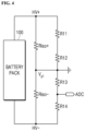
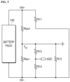
- FIGS. 4 and 5 are equivalent circuit diagrams of the insulation resistance measuring device according to the on/off of the switch.
- FIG. 4 is an equivalent circuit diagram when the switch is turned off
- FIG. 5 is an equivalent circuit diagram when the switch is turned on.
- V x 1 V pack 1 ⁇ 1 R iso + + 1 R p 1 R iso + + 1 R p + 1 R iso ⁇ + 1 R n
- V x 2 V pack 2 ⁇ 1 R iso + 1 R iso + + 1 R iso ⁇ + 1 p ⁇ R p + 1 R n
- Vx2 is the second voltage
- Vpack2 is the voltage of the battery pack when the switch is turned on
- Riso+ and Riso- are the resistance value of the positive insulation resistor and the resistance value of the negative insulation resistor, respectively
- Rp and Rn may be obtained as follows.
- R 11 R p ⁇ 1 ⁇ p
- R 12 R p ⁇ p
- R 11 + R 12 R p
- R 13 R n ⁇ 1 ⁇ n
- R 14 R n ⁇ n
- R 13 + R 14 R n
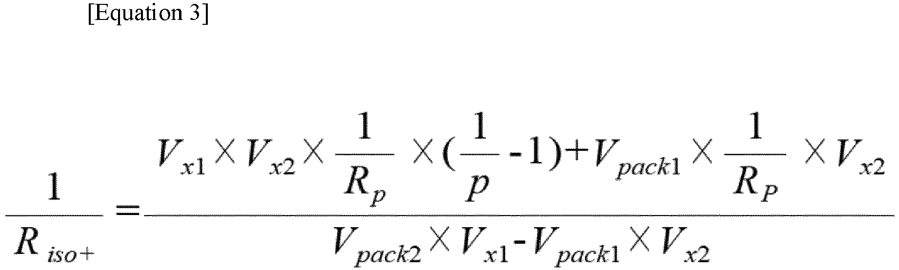
- the resistance value of the positive insulation resistor Riso+ may be obtained by [Equation 1] and [Equation 2]
- the resistance value of the negative insulation resistor Riso- may be obtained by [Equation 3] and [Equation 4]. That is, [Equation 3] is an equation for calculating the resistance value of the positive insulation resistor Riso+ by combining [Equation 1] and [Equation 2]
- [Equation 4] is an equation for calculating the resistance value of the negative insulation resistor Riso- by using [Equation 2].
Landscapes
- General Physics & Mathematics (AREA)
- Physics & Mathematics (AREA)
- Engineering & Computer Science (AREA)
- Power Engineering (AREA)
- Sustainable Development (AREA)
- Sustainable Energy (AREA)
- Life Sciences & Earth Sciences (AREA)
- Transportation (AREA)
- Mechanical Engineering (AREA)
- Chemical & Material Sciences (AREA)
- Combustion & Propulsion (AREA)
- Measurement Of Resistance Or Impedance (AREA)
- Testing Of Short-Circuits, Discontinuities, Leakage, Or Incorrect Line Connections (AREA)
Abstract
Description
- The present disclosure relates to an insulation resistance measuring device of a battery pack, and more particularly, to an insulation resistance measuring device capable of reducing the number of components.
- As a demand for portable electronic products such as laptop computers and mobile phones is significantly increasing, and electric vehicles, energy storage batteries, robots, and satellites are seriously developed, researches on a high-performance secondary battery capable of being repeatedly charged and discharged is being actively performed.
- The secondary battery that is currently commercialized includes a nickel cadmium battery, a nickel hydrogen battery, a nickel zinc battery, and a lithium secondary battery. Among the commercialized secondary batteries, the lithium secondary battery is widely used due to an extremely low self-discharge rate and a high energy density.
- Although the secondary battery is sometimes used as a single secondary battery, in general, a plurality of secondary batteries are connected in series and/or parallel to provide a high-voltage and/or large-capacity power storage device. That is, a battery module in which a plurality of battery cells of the secondary battery are connected or a battery pack in which a plurality of battery modules are connected may be used under a condition requiring high capacity such as an electric vehicle, an energy storage system, and an uninterruptible power supply.
- For the power storage device using high-voltage and large-capacity secondary battery, e.g., an electric vehicle including a battery pack, maintaining of an insulation state is extremely important. Here, insulation represents a feature of distinguishing a high-voltage region and a low-voltage region in an electric and electronic device such as an electric vehicle. When an insulation state of the battery pack is not maintained, leakage current may occur to cause various limitations. That is, the leakage current may shorten a lifespan of the battery pack, cause an error of the electric and electronic device using the battery pack, and also cause a safety accident such as electric shock.
- In order to prevent the above-described limitations caused by the leakage current, an insulation resistor at a certain level or more is required. Here, the insulation resistor is disposed between the high-voltage region and the low-voltage region. For example, when a high-voltage battery pack is used for an electric vehicle, the insulation resistor is disposed between positive and negative electrodes of a battery pack and a chassis of a vehicle, i.e., the ground, and a resistance value of the insulation resistor needs to be measured and kept from falling below a certain level. The battery pack includes an insulation resistance measuring device to measure the insulation resistance value. The insulation resistance measuring device measures the insulation resistor frequently or periodically to check the insulation state by a battery management system (BMS).
- The insulation resistor includes a positive insulation resistor disposed between a positive electrode of a high-voltage battery pack and the ground and a negative insulation resistor disposed between a negative electrode and the ground. A typical insulation resistance measuring device for measuring the above-described insulation resistor includes first and second resistors for voltage distribution, which are connected in parallel with the positive insulation resistor disposed between the positive electrode and the ground, and third and fourth resistors for voltage distribution, which are connected in parallel with the negative insulation resistor disposed between the negative electrode and the ground. Here, a first output signal is output from between the first and second resistors, and a second output signal is output from between the third and fourth resistors. Also, a first switch is disposed between the positive electrode and the first resistor, and a second switch is disposed between the negative electrode and the fourth resistor. Also, a voltage source of 5 V is connected between the ground and the third resistor R3.
- However, the above-described typical insulation resistance measuring device requires the two switches and the voltage source of 5V. Also, since the two switches are turned on and off, a switching operation of the switches increases. Thus, a circuit is complicated, and a driving method is complicated. Also, since the first and second output signals are input to first and second input terminals of an analog-digital converter through two voltage distribution resistors, two or more input terminals of the analog-digital converter are required.
- The related art is shown in documents below.
- Patent document:
Korean Patent Registration No. 10-1771226 - Non-patent document: Internet Weblog (https://m.blog.naver.com/thewoodypark/222037678937)
- The present disclosure provides an insulation resistance measuring device capable of reducing the number of switches and simplifying a configuration and a driving method because a voltage source is not required.
- The present disclosure also provides an insulation resistance measuring device capable of reducing the number of output terminals to reduce the number of input terminals of an analog-digital converter.
- In accordance with an exemplary embodiment, an insulation resistance measuring device for measuring a positive insulation resistor disposed between a positive electrode of a battery pack and a ground and a negative insulation resistor disposed between the ground and a negative electrode of the battery pack includes: first and second resistors connected in series between the positive electrode of the battery pack and the ground; third and fourth resistors connected in series between the ground and the negative electrode of the battery pack; an output terminal connected between the third and fourth resistors; and a switch connected between a contact between the first and second resistors and the negative electrode of the battery pack.
- The first and second resistors may be connected in parallel with the positive insulation resistor, and the third and fourth resistors may be connected in parallel with the negative insulation resistor.
- A distribution voltage of a first voltage between the positive insulation resistor and the negative insulation resistor may be output from the output terminal when the switch is turned off, a distribution voltage of a second voltage between the positive insulation resistor and the negative insulation resistor may be output from the output terminal when the switch is turned on, and the insulation resistance may be calculated by using the first and second voltages.
- The first voltage may be calculated by [Equation 1] below.

- Here, Vx1 is the first voltage, Vpack1 is a voltage of the battery pack when the switch is turned off, Riso+ and Riso- are a resistance value of the positive insulation resistor and a resistance value of the negative insulation resistor, respectively, and

- The second voltage may be calculated by [Equation 2] below.

- Here, Vx2 is the second voltage, Vpack2 is a voltage of the battery pack when the switch is turned on, Riso+ and Riso- are a resistance value of the positive insulation resistor and a resistance value of the negative insulation resistor, respectively, and

- The resistance value of the positive insulation resistor may be calculated by [Equation 3] that is obtained from [Equation 1] and [Equation 2].

- The resistance value of the negative insulation resistor may be calculated by [Equation 4] that is obtained from [Equation 2].

- The insulation resistance measuring device may further include: a control unit configured to control the switch; a voltage measurement unit configured to measure an output voltage of the output terminal and calculate the first and second voltages; a determination unit configured to determine whether a voltage measured by the voltage measurement unit is within a set range; and a calculation unit configured to calculate resistance values of the positive insulation resistor and the negative insulation resistor according to a determination result of the determination unit.
- The insulation resistance measuring device in accordance with the exemplary embodiment may reduce the number of switches and may not require the voltage source. Thus, the configuration and driving method of the insulation resistance measuring device may be simplified. Also, one output signal is output, and the output signal is input to the analog-digital converter. Thus, the analog-digital converter requires one input terminal to input the output signal of the insulation resistance measuring device. That is, the number of output terminals may be reduced, and accordingly, the number of input terminals of the analog-digital converter for inputting the output of the insulation resistance measuring device may be reduced in comparison with the related art. As a result, in accordance with the exemplary embodiment, the configuration and driving method of the insulation resistance measuring device may be simplified in comparison with the related art, and the configuration of the peripheral devices that receive signals from the insulation resistance measuring device may be simplified in comparison with the related art.
-
-
FIG. 1 is a circuit diagram of a typical insulation resistance measuring device. -
FIG. 2 is a circuit diagram of an insulation resistance measuring device in accordance with an exemplary embodiment. -
FIG. 3 is a circuit diagram of an insulation resistance measuring device in accordance with another exemplary embodiment. -
FIGS. 4 and5 are equivalent circuit diagrams of the insulation resistance measuring device in accordance with an exemplary embodiment. - Hereinafter, specific embodiments will be described in detail with reference to the accompanying drawings. The present disclosure may, however, be embodied in different forms and should not be construed as limited to the embodiments set forth herein. Rather, these embodiments are provided so that this disclosure will be thorough and complete, and will fully convey the scope of the present disclosure to those skilled in the art.
-
FIG. 1 is a circuit diagram of a typical insulation resistance measuring device. The typical insulation resistance measuring device measures a positive insulation resistor Riso+ disposed between a positive electrode HV+ of a highvoltage battery pack 10 and a ground and a negative insulation resistor Riso- disposed between a negative electrode HV- and the ground. - As illustrated in
FIG. 1 , the typical insulation resistance measuring device includes first and second resistors R1 and R2 for voltage distribution, which are connected in parallel with the positive insulation resistor Riso+ disposed between the positive electrode HV+ and the ground and third and fourth resistors R3 and R4 for voltage distribution, which are connected in parallel with the negative insulation resistor Riso- disposed between the negative electrode HV- and the ground. Here, a first output signal ADC1 is output from between the first and second resistors R1 and R2, and a second output signal ADC2 is output from between the third and fourth resistors R3 and R4. That is, a distribution voltage between the first and second resistors R1 and R2 is input to a first input terminal of an analog-digital converter, and a distribution voltage between the third and fourth resistors R3 and R4 is input to a second input terminal of the analog-digital converter. Also, a first switch SW1 is disposed between the positive electrode HV+ and the first resistor R1, and a second switch SW2 is disposed between the negative electrode HV- and the fourth resistor R4. Also, a voltage source of 5 V is connected between the ground and the third resistor R3. The voltage source is connected between the third resistor R3 and the ground and applies a voltage so that the voltage applied between the third resistor R3 and the ground has a positive value. - The typical insulation resistance measuring device determines a measurement cycle to repeatedly turn on and off the first and second switches SW1 and SW2. Here, the first and second switches SW1 and SW2 may be simultaneously turned on or off or alternately turned on and off depending on the cycle. As a positive voltage V positive between the positive electrode HV+ and the ground is distributed (ratio: R2/R1+R2) when the first switch SW 1 is turned on, the first output signal ADC 1 is measured, and on the contrary, as a negative voltage V negative between the negative electrode HV- and the ground is distributed when the second switch SW2 is turned on, the second output signal ADC2 is measured.
- However, the above-described typical insulation resistance measuring device requires the two switches and the voltage source of 5V Also, since the two switches are turned on and off, a switching operation of the switches increases. Thus, a circuit is complicated, and a driving method is complicated. Also, since the first and second output signals are input to the first and second input terminals of the analog-digital converter through two voltage distribution resistors, two or more input terminals of the analog-digital converter are required.
-
FIG. 2 is a circuit diagram of an insulation resistance measuring device in accordance with an exemplary embodiment, andFIG. 3 is a block diagram of the insulation resistance measuring device in accordance with an exemplary embodiment. That is,FIG. 3 is a block diagram illustrating the insulation resistance measuring device and peripheral devices thereof in accordance with an exemplary embodiment. - Referring to
FIGS. 2 and3 , the insulation resistance measuring device in accordance with an exemplary embodiment may measure the positive insulation resistor Riso+ and the negative insulation resistor Riso- disposed between the positive electrode HV+ and the negative electrode HV- of thebattery pack 100. The positive insulation resistor Riso+ is disposed between the ground and the positive electrode HV+ of thebattery pack 100, and the negative insulation resistor Riso- is disposed between the ground and the negative electrode HV- of thebattery pack 100. The insulation resistance measuring device that measures the insulation resistors Riso+ and Riso- in accordance with an exemplary embodiment may include first and second resistors R11 and R12 for voltage distribution, which are disposed between the positive electrode HV+ and the ground and are connected in parallel with the positive insulation resistor Riso+, third and fourth resistors R13 and R14 for voltage distribution, which are disposed between the negative electrode HV- and the ground and connected in parallel with the negative insulation resistor Riso-, and a switch SW disposed between the negative electrode HV- and the first and second resistors R11 and R12. That is, the insulation resistance measuring device in accordance with an exemplary embodiment reduces the number of switches and does not require a voltage source in comparison with the related art described inFIG. 1 . - The first and second resistors R11 and R12 may be disposed between the positive electrode HV+ and the ground and connected in parallel with the positive insulation resistor Riso+. Here, a resistance value of the first resistor R11 and a resistance value of the second resistor R12 may have a set resistance ratio. Here, the set resistance ratio may be a ratio between the resistance value of the first resistor R11 and the resistance value of the second resistor R12, which is set to lower and measure a voltage of the
battery pack 100 applied to the first resistor R11. - The third and fourth resistors R13 and R14 may be disposed between the negative electrode HV- and the ground and connected in parallel with the negative insulation resistor Riso-. Here, a resistance value of the third resistor R13 and a resistance value of the fourth resistor R14 may have a set resistance ratio. Here, the set resistance ratio may be a ratio between the resistance value of the third resistor R13 and the resistance value of the fourth resistor R14, which is set to lower and measure the voltage of the
battery pack 100 applied to the third resistor R13. Also, an output signal ADC may be output from between the third and fourth resistors R13 and R14. The output signal ADC between the third and fourth resistors R13 and R14, i.e., a distribution voltage between the third and fourth resistors R13 and R14, may be input to the analog-digital converter. That is, the insulation resistance measuring device in accordance with an exemplary embodiment outputs one output signal, and the output signal is input to the analog-digital converter. Thus, the analog-to-digital converter requires one input terminal to input the output signal of the insulation resistance measuring device. That is, the number of output terminals may be reduced, and accordingly, the number of input terminals of the analog-to-digital converter for inputting the output of the insulation resistance measuring device may be reduced in comparison with the related art. - The switch SW is disposed between the first and second resistors R11 and R12 and the negative electrode HV-. That is, the switch SW is disposed between a node between the first and second resistors R11 and R12 and the negative electrode HV-. The switch SW may be turned on and off to adjust a voltage of the output terminal ADC. That is, a distribution voltage of a first voltage Vx1 and a distribution voltage of a second voltage Vx2 are output from between the third and fourth resistors R13 and R14 according to the on and off of the switch SW. The distribution voltage of the first voltage Vx1 and the distribution voltage of the second voltage Vx2 are output according to the on/off of the switch SW, and accordingly, the first voltage Vx1 and the second voltage Vx2 are calculated and resistance values of the positive insulation resistor Riso+ and the negative insulation resistor Riso- may be calculated.
- As illustrated in
FIG. 3 , the insulation resistance measuring device in accordance with an exemplary embodiment may further include acontrol unit 210 controlling the switch SW, avoltage measurement unit 220 measuring a voltage of the output signal from between the third and fourth resistors R13 and R14, adetermination unit 230 determining whether the voltage measured by thevoltage measurement unit 220 is within a set range, and acalculation unit 240 calculating the resistance values of the positive insulation resistor Riso+ and the negative insulation resistor Riso- according to a determination result of thedetermination unit 230. - The
control unit 210 may control the switch SW. That is, thecontrol unit 210 may control the switch SW to turn on and off the switch SW. Thecontrol unit 210 may periodically control the switch SW and allow on and off cycles to be the same as each other. Alternatively, thecontrol unit 210 may intermittently control the switch SW and allow the on and off cycles to be different from each other. Thecontrol unit 210 may control the switch SW according to the determination result of thedetermination unit 230. - The
voltage measurement unit 220 measures a voltage of the output signal from between the third and fourth resistors R13 and R14. That is, a distribution voltage of the first voltage Vx1 and a distribution voltage of the second voltage Vx2 are output from between the third and fourth resistors R13 and R14 according to the on and off of the switch SW, and thevoltage measurement unit 220 calculates the first voltage Vx1 and the second voltage Vx2. That is, thevoltage measurement unit 220 measures the distribution voltage of the first voltage Vx1 and the distribution voltage of the second voltage Vx2 and calculates the first voltage Vx1 and the second voltage Vx2 based on the measured distribution voltages. Here, thevoltage measurement unit 220 calculates the first voltage Vx1 by [Equation 1], which will be described later, and calculates the second voltage Vx2 by [Equation 2], which will be described later. Also, thevoltage measurement unit 220 may include an analog-to-digital converter that converts an analog voltage signal into a digital voltage signal. That is, thevoltage measurement unit 220 may include the analog-to-digital converter and measure a voltage after analog voltage signals of the distribution voltage of the first voltage Vx1 and the distribution voltage of the second voltage Vx2 output from between the third and fourth resistors R13 and R14 is converted into digital voltage signals. - The
determination unit 230 may determine whether the first voltage Vx1 and the second voltage Vx2 calculated by thevoltage measurement unit 220 are within a set voltage range. That is, thedetermination unit 230 may determine whether measured values of the first voltage Vx1 and the second voltage Vx2 are within the set range and transmit a determination result to thecontrol unit 210 and thecalculation unit 240. Thedetermination unit 230 may compare the measured value of the first voltage Vx1 with a set range value and determine that the first voltage Vx1 is normal when the measured value of the first voltage Vx1 is within the set range. Similarly, thedetermination unit 230 may compare the measured value of the second voltage Vx2 with the set range value and determine that the second voltage Vx2 is normal when the measured value of the second voltage Vx2 is within the set range. - The
control unit 210 may turn off the switch SW when the first voltage Vx1 is determined as normal based on the determination result of thedetermination unit 230 and turn on the switch SW when the second voltage Vx2 is determined as normal. Through this, thecontrol unit 210 may reduce a time required to measure an insulation resistor by flexibly changing a cycle of switching an on or off state of the switch SW for insulation resistance measurement according to whether the first voltage Vx1 and the second voltage Vx2 are coverged instead of setting the cycle. - The
calculation unit 240 may calculates resistance values of the positive insulation resistor Riso+ and the negative insulation resistor Riso- by using the first voltage Vx1 at the time when the first voltage Vx1 is determined as normal from thedetermination unit 230, the second voltage Vx2 at the time when the second voltage Vx2 is determined as normal from thedetermination unit 230, and the voltage of thebattery pack 100 at the time of calculation. Here, thecalculation unit 240 may calculates the first and second voltages by using [Equation 1] and [Equation 2], which will be described later, and the positive insulation resistor Riso+ and the negative insulation resistor Riso- by using [Equation 3] and [Equation 4], which will be described later. The voltage of thebattery pack 100 may be received from a battery management system (BMS) that manages the battery pack. - As described above, the insulation resistance measuring device in accordance with an exemplary embodiment may reduce the number of switches and may not require the voltage source in comparison with the related art described in
FIG. 1 . Also, in accordance with an exemplary embodiment, one output signal is output, and the output signal is input to the analog-digital converter. Thus, the analog-digital converter requires one input terminal to input the output signal of the insulation resistance measuring device. That is, the number of output terminals may be reduced, and accordingly, the number of input terminals of the analog-digital converter for inputting the output of the insulation resistance measuring device may be reduced in comparison with the related art. -
FIGS. 4 and5 are equivalent circuit diagrams of the insulation resistance measuring device according to the on/off of the switch.FIG. 4 is an equivalent circuit diagram when the switch is turned off, andFIG. 5 is an equivalent circuit diagram when the switch is turned on. - As illustrated in
FIG. 4 , when the switch is turned off, the first voltage Vx1 output from between the positive insulation resistor Riso+ and the negative insulation resistor Riso-may be obtained by Equation 1 below.
- Here, Vx1 is the first voltage, Vpack1 is the voltage of the battery pack when the switch is turned off, Riso+ and Riso- are the resistance value of the positive insulation resistor and the resistance value of the negative insulation resistor, respectively, and Rp and Rn may be obtained as follows.

- As illustrated in
FIG. 5 , when the switch is turned on, the second voltage Vx2 output from between the positive insulation resistor Riso+ and the negative insulation resistor Riso-may be obtained by [Equation 2] below.
- Here, Vx2 is the second voltage, Vpack2 is the voltage of the battery pack when the switch is turned on, Riso+ and Riso- are the resistance value of the positive insulation resistor and the resistance value of the negative insulation resistor, respectively, and Rp and Rn may be obtained as follows.

- The resistance value of the positive insulation resistor Riso+ may be obtained by [Equation 1] and [Equation 2], and the resistance value of the negative insulation resistor Riso- may be obtained by [Equation 3] and [Equation 4]. That is, [Equation 3] is an equation for calculating the resistance value of the positive insulation resistor Riso+ by combining [Equation 1] and [Equation 2], and [Equation 4] is an equation for calculating the resistance value of the negative insulation resistor Riso- by using [Equation 2].


- As described above, the technical idea of the present invention has been specifically described with respect to the above embodiments, but it should be noted that the foregoing embodiments are provided only for illustration while not limiting the present invention. Also, various embodiments may be provided to allow those skilled in the art to understand the scope of the preset invention, but the present invention is not limited thereto.
- The reference numerals used in the drawings in the present invention are as follows.
-
100: Battery pack R11, R12, R13, R14: First to fourth resistors SW: Switch Vx1, Vx2: First and second voltages 210: Control unit 220: Voltage measurement unit 230: Determination unit 240: Calculation unit
Claims (8)
- An insulation resistance measuring device for measuring a positive insulation resistor disposed between a positive electrode of a battery pack and a ground and a negative insulation resistor disposed between the ground and a negative electrode of the battery pack, comprising:first and second resistors connected in series between the positive electrode of the battery pack and the ground;third and fourth resistors connected in series between the ground and the negative electrode of the battery pack;an output terminal connected between the third and fourth resistors; anda switch connected between a contact between the first and second resistors and the negative electrode of the battery pack.
- The insulation resistance measuring device of claim 1, wherein the first and second resistors are connected in parallel with the positive insulation resistor, and the third and fourth resistors are connected in parallel with the negative insulation resistor.
- The insulation resistance measuring device of claim 1 or 2, wherein a distribution voltage of a first voltage between the positive insulation resistor and the negative insulation resistor is output from the output terminal when the switch is turned off, a distribution voltage of a second voltage between the positive insulation resistor and the negative insulation resistor are output from the output terminal when the switch is turned on, and the insulation resistance is calculated by using the first and second voltages.
- The insulation resistance measuring device of claim 3, wherein the first voltage is calculated by [Equation 1] below.


- The insulation resistance measuring device of claim 4, wherein the second voltage is calculated by [Equation 2] below.


- The insulation resistance measuring device of claim 5, wherein the resistance value of the positive insulation resistor is calculated by [Equation 3] that is obtained from [Equation 1] and [Equation 2].
- The insulation resistance measuring device of claim 6, wherein the resistance value of the negative insulation resistor is calculated by [Equation 4] that is obtained from [Equation 2].

- The insulation resistance measuring device of claim 7, further comprising:a control unit configured to control the switch;a voltage measurement unit configured to measure an output voltage of the output terminal and calculate the first and second voltages;a determination unit configured to determine whether a voltage measured by the voltage measurement unit is within a set range; anda calculation unit configured to calculate resistance values of the positive insulation resistor and the negative insulation resistor according to a determination result of the determination unit.
Applications Claiming Priority (2)
| Application Number | Priority Date | Filing Date | Title |
|---|---|---|---|
| KR1020210155752A KR102920220B1 (en) | 2021-11-12 | 2021-11-12 | Apparatus for measuring insulation resistance |
| PCT/KR2022/017562 WO2023085777A1 (en) | 2021-11-12 | 2022-11-09 | Insulation resistance measurement device |
Publications (3)
| Publication Number | Publication Date |
|---|---|
| EP4239350A1 true EP4239350A1 (en) | 2023-09-06 |
| EP4239350A4 EP4239350A4 (en) | 2024-06-05 |
| EP4239350B1 EP4239350B1 (en) | 2025-10-15 |
Family
ID=86336178
Family Applications (1)
| Application Number | Title | Priority Date | Filing Date |
|---|---|---|---|
| EP22893197.8A Active EP4239350B1 (en) | 2021-11-12 | 2022-11-09 | Insulation resistance measurement device |
Country Status (7)
| Country | Link |
|---|---|
| US (1) | US12422493B2 (en) |
| EP (1) | EP4239350B1 (en) |
| JP (1) | JP7636067B2 (en) |
| KR (1) | KR102920220B1 (en) |
| CN (1) | CN116583751A (en) |
| ES (1) | ES3059035T3 (en) |
| WO (1) | WO2023085777A1 (en) |
Families Citing this family (2)
| Publication number | Priority date | Publication date | Assignee | Title |
|---|---|---|---|---|
| CN116754839A (en) * | 2023-06-20 | 2023-09-15 | 合众新能源汽车股份有限公司 | Insulation detection method and system of electric automobile and electric automobile |
| KR20250035261A (en) * | 2023-09-05 | 2025-03-12 | 주식회사 엘지에너지솔루션 | Isolation diagnostic circuit and battery system comprising the same |
Family Cites Families (35)
| Publication number | Priority date | Publication date | Assignee | Title |
|---|---|---|---|---|
| JPH01165973A (en) * | 1987-12-23 | 1989-06-29 | Kawasaki Steel Corp | Measuring device of insulation resistance of direct-current circuit |
| JP3590679B2 (en) | 1995-09-18 | 2004-11-17 | 株式会社ケーヒン | Abnormality detection device for floating DC power supply |
| JP3962990B2 (en) | 2002-11-18 | 2007-08-22 | 矢崎総業株式会社 | Insulation detector for ungrounded power supply |
| JP4280145B2 (en) | 2003-10-23 | 2009-06-17 | 矢崎総業株式会社 | Insulation resistance drop detector and self-diagnosis method thereof |
| JP2006220520A (en) | 2005-02-10 | 2006-08-24 | Honda Motor Co Ltd | Insulation resistance measuring apparatus and method for non-grounded DC power supply |
| KR101291724B1 (en) * | 2007-09-04 | 2013-07-31 | 주식회사 엘지화학 | Apparatus and Method for sensing leakage current of battery |
| JP4759018B2 (en) * | 2008-05-26 | 2011-08-31 | 矢崎総業株式会社 | Insulation measuring device |
| KR101043445B1 (en) | 2009-03-23 | 2011-06-22 | 에스케이이노베이션 주식회사 | Insulation resistance measuring circuit using resistance connected to battery |
| JP2012173053A (en) | 2011-02-18 | 2012-09-10 | Mitsubishi Heavy Ind Ltd | Electric leak detecting device and method for the same |
| CN202166682U (en) * | 2011-07-20 | 2012-03-14 | 珠海泰坦新能源系统有限公司 | A direct grounding insulation fault detection device |
| WO2013147494A1 (en) | 2012-03-26 | 2013-10-03 | 주식회사 엘지화학 | Device and method for measuring insulation resistance of battery |
| PL2796887T3 (en) | 2012-03-27 | 2020-05-18 | Lg Chem, Ltd. | Isolation resistance measurement apparatus having fault self-diagnosis function and fault self-diagnosing method using the same |
| PL2720056T3 (en) * | 2012-04-04 | 2021-07-12 | Lg Chem, Ltd. | Isolation resistance measuring apparatus having fault self-diagnosing function and self-diagnosing method using the same |
| KR101473396B1 (en) * | 2012-05-15 | 2014-12-16 | 주식회사 엘지화학 | Apparatus and method for measuring isolation resistance of battery using extended kalman filter |
| KR101389362B1 (en) | 2012-09-27 | 2014-04-25 | 현대오트론 주식회사 | Apparatus and method for measuring insulation resistance |
| DE102013215731A1 (en) | 2013-08-09 | 2015-02-12 | Volkswagen Aktiengesellschaft | Method and device for measuring one or more insulation resistances in a motor vehicle |
| KR101771226B1 (en) | 2014-10-02 | 2017-09-05 | 주식회사 엘지화학 | Isolation resistance measurement apparatus that can rapidly measure isolation resistance |
| JP6609984B2 (en) * | 2015-05-11 | 2019-11-27 | 富士電機株式会社 | Insulation resistance measuring method and apparatus |
| KR101936220B1 (en) | 2015-11-16 | 2019-01-08 | 주식회사 엘지화학 | System and apparatus for measuring of insulation resistance |
| JP6753715B2 (en) | 2016-07-20 | 2020-09-09 | 株式会社東芝 | Leakage detection device and leakage detection method |
| KR101991910B1 (en) | 2016-11-16 | 2019-06-21 | 주식회사 엘지화학 | Apparatus and method for measuring isolation resistance of battery |
| KR102065822B1 (en) | 2017-06-27 | 2020-02-11 | 주식회사 엘지화학 | System and method for calculating insulation resistance |
| CN107526041A (en) * | 2017-08-29 | 2017-12-29 | 宁德时代新能源科技股份有限公司 | Battery detection circuit and battery management system |
| JP6698599B2 (en) * | 2017-09-21 | 2020-05-27 | 矢崎総業株式会社 | Ground fault detector |
| CN108872812B (en) | 2018-06-29 | 2021-01-01 | 深圳市国新动力科技有限公司 | Low-cost insulation leakage detection circuit and detection method |
| TWI661204B (en) * | 2018-07-16 | 2019-06-01 | 昆山富士錦電子有限公司 | Insulation resistance measuring device |
| CN110873845A (en) | 2018-08-31 | 2020-03-10 | 宁德时代新能源科技股份有限公司 | A kind of insulation detection method |
| KR102703105B1 (en) | 2018-11-02 | 2024-09-04 | 주식회사 엘지에너지솔루션 | Apparatus and method for switch diagnosis using voltage distribution |
| KR102699851B1 (en) | 2018-11-20 | 2024-08-27 | 주식회사 엘지에너지솔루션 | System and method for isolating the resistor diagnosis |
| KR102742037B1 (en) | 2019-01-03 | 2024-12-13 | 주식회사 엘지에너지솔루션 | Insulation resistance measurement apparatus and method thereof |
| KR102155207B1 (en) | 2019-07-05 | 2020-09-11 | 주식회사 라온텍 | Insulation resistance measuring apparatus, battery management system having the same and insulation resistance measuring method |
| KR102731446B1 (en) | 2019-11-18 | 2024-11-15 | 주식회사 엘지에너지솔루션 | Apparatus for estimating Insulation Resistance and Battery System using the same |
| KR102804359B1 (en) | 2020-04-13 | 2025-05-09 | 에스케이온 주식회사 | Apparatus for measuring insulation resistance |
| CN213813774U (en) * | 2020-09-30 | 2021-07-27 | 郑州深澜动力科技有限公司 | Insulation resistance detection device for new energy vehicle |
| EP4317997A4 (en) | 2021-03-31 | 2024-10-02 | Nuvoton Technology Corporation Japan | Earth leakage detecting circuit, and battery state detecting circuit |
-
2021
- 2021-11-12 KR KR1020210155752A patent/KR102920220B1/en active Active
-
2022
- 2022-11-09 WO PCT/KR2022/017562 patent/WO2023085777A1/en not_active Ceased
- 2022-11-09 CN CN202280008114.3A patent/CN116583751A/en active Pending
- 2022-11-09 EP EP22893197.8A patent/EP4239350B1/en active Active
- 2022-11-09 US US18/269,855 patent/US12422493B2/en active Active
- 2022-11-09 JP JP2023534231A patent/JP7636067B2/en active Active
- 2022-11-09 ES ES22893197T patent/ES3059035T3/en active Active
Also Published As
| Publication number | Publication date |
|---|---|
| US12422493B2 (en) | 2025-09-23 |
| ES3059035T3 (en) | 2026-03-16 |
| KR102920220B1 (en) | 2026-01-30 |
| KR20230069593A (en) | 2023-05-19 |
| JP2023553024A (en) | 2023-12-20 |
| CN116583751A (en) | 2023-08-11 |
| EP4239350B1 (en) | 2025-10-15 |
| EP4239350A4 (en) | 2024-06-05 |
| WO2023085777A1 (en) | 2023-05-19 |
| JP7636067B2 (en) | 2025-02-26 |
| US20240319284A1 (en) | 2024-09-26 |
Similar Documents
| Publication | Publication Date | Title |
|---|---|---|
| KR102731446B1 (en) | Apparatus for estimating Insulation Resistance and Battery System using the same | |
| US6891352B2 (en) | Battery apparatus for controlling plural batteries and control method of plural batteries | |
| KR101497602B1 (en) | Balancing system for battery and Method for balancing of battery using the same | |
| US8207741B2 (en) | Apparatus and method for sensing leakage current of battery, and battery-driven apparatus and battery pack comprising the apparatus | |
| US8421466B2 (en) | Apparatus and method for sensing leakage current of battery | |
| KR100993080B1 (en) | Apparatus and method for measuring battery cell voltage using insulated capacitors | |
| CN113824173B (en) | Battery control unit and battery system | |
| US20130187611A1 (en) | Cell voltage equalizer for multi-cell battery pack | |
| EP4239350A1 (en) | Insulation resistance measurement device | |
| EP3907813B1 (en) | Temperature measuring apparatus, battery apparatus including the same and temperature measuring method | |
| JP2009286292A (en) | Vehicular power supply device | |
| US20160266211A1 (en) | Remaining battery life prediction device and battery pack | |
| JP6809911B2 (en) | Differential voltage measuring device | |
| US8680867B2 (en) | Battery monitoring circuit and battery monitoring system | |
| JP5100141B2 (en) | Power supply for vehicle | |
| EP4481885A1 (en) | Overheating diagnosis method, and overheating diagnosis apparatus and battery system providing same | |
| KR102005397B1 (en) | Apparatus for diagnosing high voltage secondary battery fuse | |
| JP4974593B2 (en) | Power supply for vehicle | |
| JP2023553024A5 (en) | ||
| US12523705B2 (en) | Battery apparatus and current sensor diagnosis method | |
| KR20230094883A (en) | Apparatus and operating method for measuring insulation resistance of battery | |
| CN113884919A (en) | Current acquisition circuit, integrated device and battery management system | |
| KR20210051449A (en) | Information Processing Method of Battery Management System and Battery System | |
| US20260121426A1 (en) | Cell balancing circuit and battery device | |
| KR102745194B1 (en) | Appratus and method for measuring voltage of battery |
Legal Events
| Date | Code | Title | Description |
|---|---|---|---|
| STAA | Information on the status of an ep patent application or granted ep patent |
Free format text: STATUS: THE INTERNATIONAL PUBLICATION HAS BEEN MADE |
|
| PUAI | Public reference made under article 153(3) epc to a published international application that has entered the european phase |
Free format text: ORIGINAL CODE: 0009012 |
|
| STAA | Information on the status of an ep patent application or granted ep patent |
Free format text: STATUS: REQUEST FOR EXAMINATION WAS MADE |
|
| 17P | Request for examination filed |
Effective date: 20230531 |
|
| AK | Designated contracting states |
Kind code of ref document: A1 Designated state(s): AL AT BE BG CH CY CZ DE DK EE ES FI FR GB GR HR HU IE IS IT LI LT LU LV MC ME MK MT NL NO PL PT RO RS SE SI SK SM TR |
|
| REG | Reference to a national code |
Ref country code: DE Ref legal event code: R079 Ref document number: 602022023262 Country of ref document: DE Free format text: PREVIOUS MAIN CLASS: G01R0031389000 Ipc: G01R0027020000 |
|
| A4 | Supplementary search report drawn up and despatched |
Effective date: 20240508 |
|
| RIC1 | Information provided on ipc code assigned before grant |
Ipc: G01R 31/36 20200101ALI20240502BHEP Ipc: G01R 27/02 20060101AFI20240502BHEP |
|
| DAV | Request for validation of the european patent (deleted) | ||
| DAX | Request for extension of the european patent (deleted) | ||
| GRAP | Despatch of communication of intention to grant a patent |
Free format text: ORIGINAL CODE: EPIDOSNIGR1 |
|
| STAA | Information on the status of an ep patent application or granted ep patent |
Free format text: STATUS: GRANT OF PATENT IS INTENDED |
|
| RIC1 | Information provided on ipc code assigned before grant |
Ipc: B60L 58/10 20190101ALI20250506BHEP Ipc: G01R 31/36 20200101ALI20250506BHEP Ipc: G01R 27/02 20060101AFI20250506BHEP |
|
| INTG | Intention to grant announced |
Effective date: 20250515 |
|
| GRAS | Grant fee paid |
Free format text: ORIGINAL CODE: EPIDOSNIGR3 |
|
| GRAA | (expected) grant |
Free format text: ORIGINAL CODE: 0009210 |
|
| STAA | Information on the status of an ep patent application or granted ep patent |
Free format text: STATUS: THE PATENT HAS BEEN GRANTED |
|
| AK | Designated contracting states |
Kind code of ref document: B1 Designated state(s): AL AT BE BG CH CY CZ DE DK EE ES FI FR GB GR HR HU IE IS IT LI LT LU LV MC ME MK MT NL NO PL PT RO RS SE SI SK SM TR |
|
| REG | Reference to a national code |
Ref country code: GB Ref legal event code: FG4D Ref country code: CH Ref legal event code: F10 Free format text: ST27 STATUS EVENT CODE: U-0-0-F10-F00 (AS PROVIDED BY THE NATIONAL OFFICE) Effective date: 20251015 |
|
| REG | Reference to a national code |
Ref country code: IE Ref legal event code: FG4D |
|
| REG | Reference to a national code |
Ref country code: DE Ref legal event code: R096 Ref document number: 602022023262 Country of ref document: DE |
|
| P01 | Opt-out of the competence of the unified patent court (upc) registered |
Free format text: CASE NUMBER: UPC_APP_0010196_4239350/2025 Effective date: 20251017 |
|
| PGFP | Annual fee paid to national office [announced via postgrant information from national office to epo] |
Ref country code: DE Payment date: 20251208 Year of fee payment: 4 |
|
| PGFP | Annual fee paid to national office [announced via postgrant information from national office to epo] |
Ref country code: AT Payment date: 20260113 Year of fee payment: 4 |
|
| PGFP | Annual fee paid to national office [announced via postgrant information from national office to epo] |
Ref country code: FR Payment date: 20251209 Year of fee payment: 4 |
|
| PGFP | Annual fee paid to national office [announced via postgrant information from national office to epo] |
Ref country code: BE Payment date: 20251209 Year of fee payment: 4 |
|
| PGFP | Annual fee paid to national office [announced via postgrant information from national office to epo] |
Ref country code: ES Payment date: 20251215 Year of fee payment: 4 |
|
| REG | Reference to a national code |
Ref country code: NL Ref legal event code: MP Effective date: 20251015 |
|
| REG | Reference to a national code |
Ref country code: AT Ref legal event code: MK05 Ref document number: 1847361 Country of ref document: AT Kind code of ref document: T Effective date: 20251015 |
|
| REG | Reference to a national code |
Ref country code: ES Ref legal event code: FG2A Ref document number: 3059035 Country of ref document: ES Kind code of ref document: T3 Effective date: 20260316 |
|
| PG25 | Lapsed in a contracting state [announced via postgrant information from national office to epo] |
Ref country code: NL Free format text: LAPSE BECAUSE OF FAILURE TO SUBMIT A TRANSLATION OF THE DESCRIPTION OR TO PAY THE FEE WITHIN THE PRESCRIBED TIME-LIMIT Effective date: 20251015 |
|
| PGFP | Annual fee paid to national office [announced via postgrant information from national office to epo] |
Ref country code: HU Payment date: 20260129 Year of fee payment: 4 |
|
| REG | Reference to a national code |
Ref country code: LT Ref legal event code: MG9D |
|
| PG25 | Lapsed in a contracting state [announced via postgrant information from national office to epo] |
Ref country code: NO Free format text: LAPSE BECAUSE OF FAILURE TO SUBMIT A TRANSLATION OF THE DESCRIPTION OR TO PAY THE FEE WITHIN THE PRESCRIBED TIME-LIMIT Effective date: 20260115 |
|
| PG25 | Lapsed in a contracting state [announced via postgrant information from national office to epo] |
Ref country code: AT Free format text: LAPSE BECAUSE OF FAILURE TO SUBMIT A TRANSLATION OF THE DESCRIPTION OR TO PAY THE FEE WITHIN THE PRESCRIBED TIME-LIMIT Effective date: 20251015 Ref country code: HR Free format text: LAPSE BECAUSE OF FAILURE TO SUBMIT A TRANSLATION OF THE DESCRIPTION OR TO PAY THE FEE WITHIN THE PRESCRIBED TIME-LIMIT Effective date: 20251015 Ref country code: FI Free format text: LAPSE BECAUSE OF FAILURE TO SUBMIT A TRANSLATION OF THE DESCRIPTION OR TO PAY THE FEE WITHIN THE PRESCRIBED TIME-LIMIT Effective date: 20251015 |
|
| PG25 | Lapsed in a contracting state [announced via postgrant information from national office to epo] |
Ref country code: RS Free format text: LAPSE BECAUSE OF FAILURE TO SUBMIT A TRANSLATION OF THE DESCRIPTION OR TO PAY THE FEE WITHIN THE PRESCRIBED TIME-LIMIT Effective date: 20260115 |
|
| PG25 | Lapsed in a contracting state [announced via postgrant information from national office to epo] |
Ref country code: IS Free format text: LAPSE BECAUSE OF FAILURE TO SUBMIT A TRANSLATION OF THE DESCRIPTION OR TO PAY THE FEE WITHIN THE PRESCRIBED TIME-LIMIT Effective date: 20260215 |
|
| PG25 | Lapsed in a contracting state [announced via postgrant information from national office to epo] |
Ref country code: PT Free format text: LAPSE BECAUSE OF FAILURE TO SUBMIT A TRANSLATION OF THE DESCRIPTION OR TO PAY THE FEE WITHIN THE PRESCRIBED TIME-LIMIT Effective date: 20260216 |
|
| PG25 | Lapsed in a contracting state [announced via postgrant information from national office to epo] |
Ref country code: PL Free format text: LAPSE BECAUSE OF FAILURE TO SUBMIT A TRANSLATION OF THE DESCRIPTION OR TO PAY THE FEE WITHIN THE PRESCRIBED TIME-LIMIT Effective date: 20251015 |
|
| PG25 | Lapsed in a contracting state [announced via postgrant information from national office to epo] |
Ref country code: LV Free format text: LAPSE BECAUSE OF FAILURE TO SUBMIT A TRANSLATION OF THE DESCRIPTION OR TO PAY THE FEE WITHIN THE PRESCRIBED TIME-LIMIT Effective date: 20251015 |