EP4239105B1 - Kompakte tragbare knallgasvorrichtung - Google Patents
Kompakte tragbare knallgasvorrichtung Download PDFInfo
- Publication number
- EP4239105B1 EP4239105B1 EP21904838.6A EP21904838A EP4239105B1 EP 4239105 B1 EP4239105 B1 EP 4239105B1 EP 21904838 A EP21904838 A EP 21904838A EP 4239105 B1 EP4239105 B1 EP 4239105B1
- Authority
- EP
- European Patent Office
- Prior art keywords
- compact portable
- stage filter
- filter baffle
- oxyhydrogen generator
- generator according
- Prior art date
- Legal status (The legal status is an assumption and is not a legal conclusion. Google has not performed a legal analysis and makes no representation as to the accuracy of the status listed.)
- Active
Links
Images
Classifications
-
- C—CHEMISTRY; METALLURGY
- C25—ELECTROLYTIC OR ELECTROPHORETIC PROCESSES; APPARATUS THEREFOR
- C25B—ELECTROLYTIC OR ELECTROPHORETIC PROCESSES FOR THE PRODUCTION OF COMPOUNDS OR NON-METALS; APPARATUS THEREFOR
- C25B1/00—Electrolytic production of inorganic compounds or non-metals
- C25B1/01—Products
- C25B1/02—Hydrogen or oxygen
- C25B1/04—Hydrogen or oxygen by electrolysis of water
- C25B1/044—Hydrogen or oxygen by electrolysis of water producing mixed hydrogen and oxygen gas, e.g. Brown's gas [HHO]
-
- C—CHEMISTRY; METALLURGY
- C25—ELECTROLYTIC OR ELECTROPHORETIC PROCESSES; APPARATUS THEREFOR
- C25B—ELECTROLYTIC OR ELECTROPHORETIC PROCESSES FOR THE PRODUCTION OF COMPOUNDS OR NON-METALS; APPARATUS THEREFOR
- C25B15/00—Operating or servicing cells
- C25B15/02—Process control or regulation
- C25B15/023—Measuring, analysing or testing during electrolytic production
-
- C—CHEMISTRY; METALLURGY
- C25—ELECTROLYTIC OR ELECTROPHORETIC PROCESSES; APPARATUS THEREFOR
- C25B—ELECTROLYTIC OR ELECTROPHORETIC PROCESSES FOR THE PRODUCTION OF COMPOUNDS OR NON-METALS; APPARATUS THEREFOR
- C25B15/00—Operating or servicing cells
- C25B15/02—Process control or regulation
- C25B15/023—Measuring, analysing or testing during electrolytic production
- C25B15/025—Measuring, analysing or testing during electrolytic production of electrolyte parameters
-
- C—CHEMISTRY; METALLURGY
- C25—ELECTROLYTIC OR ELECTROPHORETIC PROCESSES; APPARATUS THEREFOR
- C25B—ELECTROLYTIC OR ELECTROPHORETIC PROCESSES FOR THE PRODUCTION OF COMPOUNDS OR NON-METALS; APPARATUS THEREFOR
- C25B15/00—Operating or servicing cells
- C25B15/08—Supplying or removing reactants or electrolytes; Regeneration of electrolytes
- C25B15/083—Separating products
-
- C—CHEMISTRY; METALLURGY
- C25—ELECTROLYTIC OR ELECTROPHORETIC PROCESSES; APPARATUS THEREFOR
- C25B—ELECTROLYTIC OR ELECTROPHORETIC PROCESSES FOR THE PRODUCTION OF COMPOUNDS OR NON-METALS; APPARATUS THEREFOR
- C25B15/00—Operating or servicing cells
- C25B15/08—Supplying or removing reactants or electrolytes; Regeneration of electrolytes
- C25B15/085—Removing impurities
-
- C—CHEMISTRY; METALLURGY
- C25—ELECTROLYTIC OR ELECTROPHORETIC PROCESSES; APPARATUS THEREFOR
- C25B—ELECTROLYTIC OR ELECTROPHORETIC PROCESSES FOR THE PRODUCTION OF COMPOUNDS OR NON-METALS; APPARATUS THEREFOR
- C25B9/00—Cells or assemblies of cells; Constructional parts of cells; Assemblies of constructional parts, e.g. electrode-diaphragm assemblies; Process-related cell features
-
- C—CHEMISTRY; METALLURGY
- C25—ELECTROLYTIC OR ELECTROPHORETIC PROCESSES; APPARATUS THEREFOR
- C25B—ELECTROLYTIC OR ELECTROPHORETIC PROCESSES FOR THE PRODUCTION OF COMPOUNDS OR NON-METALS; APPARATUS THEREFOR
- C25B9/00—Cells or assemblies of cells; Constructional parts of cells; Assemblies of constructional parts, e.g. electrode-diaphragm assemblies; Process-related cell features
- C25B9/17—Cells comprising dimensionally-stable non-movable electrodes; Assemblies of constructional parts thereof
-
- B—PERFORMING OPERATIONS; TRANSPORTING
- B01—PHYSICAL OR CHEMICAL PROCESSES OR APPARATUS IN GENERAL
- B01D—SEPARATION
- B01D45/00—Separating dispersed particles from gases or vapours by gravity, inertia, or centrifugal forces
- B01D45/04—Separating dispersed particles from gases or vapours by gravity, inertia, or centrifugal forces by utilising inertia
- B01D45/08—Separating dispersed particles from gases or vapours by gravity, inertia, or centrifugal forces by utilising inertia by impingement against baffle separators
-
- B—PERFORMING OPERATIONS; TRANSPORTING
- B01—PHYSICAL OR CHEMICAL PROCESSES OR APPARATUS IN GENERAL
- B01D—SEPARATION
- B01D46/00—Filters or filtering processes specially modified for separating dispersed particles from gases or vapours
- B01D46/0027—Filters or filtering processes specially modified for separating dispersed particles from gases or vapours with additional separating or treating functions
- B01D46/003—Filters or filtering processes specially modified for separating dispersed particles from gases or vapours with additional separating or treating functions including coalescing means for the separation of liquid
-
- B—PERFORMING OPERATIONS; TRANSPORTING
- B01—PHYSICAL OR CHEMICAL PROCESSES OR APPARATUS IN GENERAL
- B01D—SEPARATION
- B01D46/00—Filters or filtering processes specially modified for separating dispersed particles from gases or vapours
- B01D46/24—Particle separators, e.g. dust precipitators, using rigid hollow filter bodies
-
- Y—GENERAL TAGGING OF NEW TECHNOLOGICAL DEVELOPMENTS; GENERAL TAGGING OF CROSS-SECTIONAL TECHNOLOGIES SPANNING OVER SEVERAL SECTIONS OF THE IPC; TECHNICAL SUBJECTS COVERED BY FORMER USPC CROSS-REFERENCE ART COLLECTIONS [XRACs] AND DIGESTS
- Y02—TECHNOLOGIES OR APPLICATIONS FOR MITIGATION OR ADAPTATION AGAINST CLIMATE CHANGE
- Y02E—REDUCTION OF GREENHOUSE GAS [GHG] EMISSIONS, RELATED TO ENERGY GENERATION, TRANSMISSION OR DISTRIBUTION
- Y02E60/00—Enabling technologies; Technologies with a potential or indirect contribution to GHG emissions mitigation
- Y02E60/30—Hydrogen technology
- Y02E60/36—Hydrogen production from non-carbon containing sources, e.g. by water electrolysis
Definitions
- the present invention relates to the technical field of preparing hydrogen and oxygen, in particular to a compact portable oxyhydrogen generator according to the preamble of claim 1 (see for example CN 205 222 779 U ).
- the existing hydrogen and oxygen generation instrument is large in volume and weight, and high in price, which is only suitable for use in specific medical institutions.
- the miniaturization and lightweight of the hydrogen and oxygen generation instrument have become urgent problems to be solved.
- the present invention provides a compact portable oxyhydrogen as defined in claim 1, wherein a battery module for supplying power, an electrolytic cell module for generating hydrogen and oxygen, a water filtration cell for filtering moisture, and a multi-stage filter baffle for further filtering gas are sequentially arranged in the housing to make full use of the inner space of the housing, so as to efficiently prepare hydrogen/oxygen mixture, having the characteristics of low energy consumption, low cost, compact structure, portability, safety and noise free.
- a water level monitoring module is further provided between the electrolytic cell module and the water filtration cell, and the water level monitoring module includes a high water level indicator and a low water level floating ball connected with a sensor.
- the multi-stage filter baffle is provided with at least two stages of filter baffles.
- the water filtration cell cooperates with the end cover to lock tightly, an accommodating cavity for containing the multi-stage filter baffle is formed between the two, a middle of the water filtration cell is provided with a hollow raised portion, a middle part of the multi-stage filter baffle is provided with a centered indentation, a middle part of the raised portion is pressed against the adjacent side centered indentation of the first-stage filter baffle of the multi-stage filter baffle, and is sealed with the middle part and the periphery of the first-stage filter baffle.
- the two adjacent filter baffles have the same or different structural forms.
- the structure of the multi-stage filter baffle is a disc structure with a centered indentation corresponding to the raised portion of the water filtration cell in the middle, a disc main body thereof is provided with at least one through hole for the hydrogen/oxygen mixture to pass through, and a lower end of the disc main body is selectively provided with a plurality of auxiliary baffles.
- the structure of the multi-stage filter baffle is a screen-type disc composite structure with a plurality of air holes, where a top layer disc has a plurality of air holes and each of other discs has at least one main air hole, and a plurality of discs is staggered arrangement to form a filter structure.
- At least one electrode for reaction is provided in the electrolytic cell.
- adjacent electrodes are separated by an insulating ring.
- a sealing ring is further arranged between the water filtration cell and the end cover and the housing.
- a lower end of the bottom cover is provided with a non-slip pad.
- the present invention uses water as the reaction raw material and a cheap inorganic salt as the electrolyte, so that a normal-pressure hydrogen/oxygen mixture may be directly produced, and can be produced when needed.
- the present solution is high in safety and has characteristics such as small volume, light weight, low energy consumption, low cost, safe and noise free, and is simple in structure, high in practicability, and is portable.
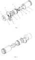
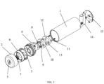
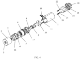
- 1 housing; 2. end cover; 3. gas outlet;4. water filtration cell; 5. first-stage filter baffle; 6. second-stage filter baffle; 7. flame retardant core; 8. high water lever indicator; 9. low water floating ball; 10. electrode; 11. screw rob; 12. reinforcement electrode; 13. insulating ring; 14. battery; 15. bottom cover; 16. third-stage filter baffle; 17. sealing ring; 18. non-slip pad; 19. power button; 20. gasket; 21. screw; 22. power connector.
- orientations or position relationships indicated by orientation terms “front, rear, upper, lower, left, and right", “transverse, vertical, perpendicular, and horizontal”, “top and bottom”, and the like are usually based on orientations or position relationships shown in the accompanying drawings, and these terms are only used to facilitate description of the present invention and simplification of the description.
- orientation terms do not indicate or imply that the apparatus or element referred to must have a specific orientation or be constructed and operated in a specific orientation, and therefore cannot be understood as a limitation on the protection scope of the present invention: orientation words “inner and outer” refer to the inside and outside relative to the contour of each component.
- spatially relative terms such as “on”, “over”, “on the upper surface”, and “above” can be used here, to describe a spatial positional relationship between one device or feature and another device or feature shown in the figures. It should be understood that the spatially relative terms are intended to include different orientations in use or operation other than the orientation of the device described in the figure. For example, if the device in the figure is inverted, the device described as “above another device or structure” or “on another device or structure” is then be positioned as being “below another device or structure” or “beneath a device or structure”. Therefore, the exemplary term “above” can include both orientations “above” and “below”. The device can also be positioned in other different ways (rotating by 90 degrees or in another orientation), and the spatially relative description used herein is explained accordingly.
- a compact portable oxyhydrogen generator including a housing 1, an end cover 2 fastened on an upper end of the housing 1 for discharging gas, and a bottom cover 15 fastened on an upper end of the housing1.
- a battery module for supplying power, an electrolytic cell module for generating hydrogen/oxygen mixture, a water filtration cell 4 for filtering moisture, and a multi-stage filter baffle for further filtering the gas are sequentially arranged in the housing 1 from bottom to top.
- the multi-stage filter baffle has two stages.
- the first-stage filter baffle 5 is adjacent to the water filtration cell 4, and a flame retardant core 7 is provided between the second-stage filter baffle 6 and the gas outlet 3 arranged in the end cover 2.
- a water level monitoring module is further provided between the electrolytic cell module and the water filtration cell 4, and the water level monitoring module includes a high water level indicator 8 and a low water level floating ball 9 connected with a sensor.
- the water level monitoring module is arranged on the electrode 10 to monitor the addition amount and usage amount of the electrolyte.
- the water filtration cell 4 cooperates with the end cover 2 to lock tightly through threads, and an accommodating cavity for containing the multi-stage filter baffle is formed therebetween. Specifically, the water filtration cell 4 is used for holding water, and the middle of the water filtration cell 4 is provided with a hollow raised portion.
- the structure of the first-stage filter baffle 5 is a disc structure with a centered indentation corresponding to the raised portion of the water filtration cell 4 in the middle part, and the middle part is an indentation structure without hollow opening; and the periphery of disc is provided with a slightly raised outer edge, the disc main body thereof (not the middle position) is provided with at least one through hole for the hydrogen/oxygen mixture to pass through, and the lower end of the disc main body is selectively provided with a plurality of auxiliary baffles.
- the auxiliary baffles may be seen from the back view of FIG. 2 .
- the middle part of the raised portion is pressed against the centered indentation of the first-stage filter baffle 5 and is sealed with the middle part and the periphery of the first-stage filter baffle 5, ensuring that the gas generated by the reaction passes through the water cell of the water filtration cell 4 and then is filtered layer by layer through the air passage beside the water filtration cell 4.
- the second-stage filter baffle 6 has the same or different structure with the first-stage filter baffle 5.
- the structure of the second-stage filter baffle 6 is a screen-type disc composite structure with a plurality of air holes, and the top layer disc is a screen with a plurality of air holes, and each of other discs has at least one main air hole.
- a plurality of discs is staggered arrangement to form a filter structure.
- the second-stage filter baffle 6 is a composite structure with two parts inlaid and closed together; and the hydrogen/oxygen mixture with water vapor condenses water vapor through the layers of filter baffles, thereby making the gas discharged from the gas outlet more dry.
- the electrolytic cell module is provided with an electrode 10 for reaction, and the electrode is tightly screwed with the fixed hole on the bottom cover 15 by the screw robs 11 passing through the baffles between the electrolytic cell module and the battery module.
- two electrodes structure are provided.
- the electrode 10 and the reinforcement electrode 12 are used in cooperation, and the two electrodes are separated by the insulating ring 13 between the two.
- the water filtration cell 4 in this embodiment can clearly see a large accommodating cavity for water storage and a gas pipe connected to the large accommodating cavity, prolonging the circulation route of the reaction gas and making the filtration more sufficient.
- the second-stage filter baffle 6 adopts a side hole-shaped structure staggered with the first-stage filter baffle 5.
- the first-stage filter baffle 5 is a plate-shaped filter baffle with a ventilation portion on one side
- the second-stage filter baffle 6 has a structure generally identical to Embodiment 1.
- a third-stage filter baffle 16 is further provided, and water vapor of the hydrogen/oxygen mixture is removed through condensation layer by layer.
- a sealing ring 17 is further provided between the water filtration cell 4, the end cover 2 and the housing 1. When the end cover 2 and the water filtration cell 4 are tightly locked, the sealing ring 17 plays a sealing effect.
- water and electrolyte can be introduced from the gas outlet 3, and then the water level monitoring module can monitor whether the water level in the electrolytic cell is appropriate.
- the power connector 22 is in contact with the battery 14, the circuit board is turned on through the power button 19 to control the whole device, and the electrode 10 starts to react and produce gas in the electrolyte module.
- the electrode 10 is fixed to the bottom cover 15 by the screw robs 11 passing through the gaskets 20 and the screws in turn. In order to be placed upright on the table top and other positions, the lower end of the bottom cover 15 is provided with a non-slip pad 18.
- the power button 19 is turned on, and the oxyhydrogen generator is started to produce gas.
- the hydrogen/oxygen mixture mixed with water vapor is produced in the electrolytic cell module and enters the water filtration cell 4, and enters the multi-stage filter baffle through the air passage.
- the water vapor condenses on the filter baffles and falls back into the electrolytic cell through the winding ventilation air passage formed among the multistage filter baffles, and the relatively dry hydrogen/oxygen mixture is finally exported from the gas outlet 3 through the flame retardant core 7 for a user to inhale.
Landscapes
- Chemical & Material Sciences (AREA)
- Engineering & Computer Science (AREA)
- Chemical Kinetics & Catalysis (AREA)
- Electrochemistry (AREA)
- Materials Engineering (AREA)
- Metallurgy (AREA)
- Organic Chemistry (AREA)
- Inorganic Chemistry (AREA)
- Analytical Chemistry (AREA)
- Automation & Control Theory (AREA)
- Electrolytic Production Of Non-Metals, Compounds, Apparatuses Therefor (AREA)
Claims (11)
- Kompakter tragbarer Knallgasgenerator, der ein Gehäuse, eine Endabdeckung, die an einem oberen Ende des Gehäuses zum Ablassen von Gas befestigt ist, und eine Bodenabdeckung, die an einem unteren Ende des Gehäuses befestigt ist, umfasst, wobei der kompakte tragbare Knallgasgenerator dadurch gekennzeichnet ist, dass ein Batteriemodul zur Stromversorgung, ein Elektrolysezellenmodul zur Erzeugung einer Wasserstoff/Sauerstoff-Mischung, eine Wasserfilterzelle zum Filtern von Feuchtigkeit und eine mehrstufige Filterplatte zum weiteren Filtern des Gases in dem Gehäuse von unten nach oben nacheinander angeordnet sind, und dass ein flammhemmender Kern zwischen der Filterplatte und der Bodenabdeckung vorgesehen ist, eine Wasserfilterzelle zum Filtern von Feuchtigkeit und ein mehrstufiges Filterprallblech zum weiteren Filtern des Gases nacheinander in dem Gehäuse von unten nach oben angeordnet sind, und dass ein flammhemmender Kern zwischen dem Filterprallblech in der oberen Schicht und einem in der Endabdeckung vorgesehenen Gasauslass vorgesehen ist und das mehrstufige Filterprallblech entsprechend den Anforderungen eines Gasfilterungsindexes vorgesehen ist.
- Kompakter tragbarer Knallgasgenerator nach Anspruch 1, wobei zwischen dem Elektrolysezellenmodul und der Wasserfiltrationszelle ein Wasserstandsüberwachungsmodul vorgesehen ist und das Wasserstands überwachungsmodul eine Anzeige für einen hohen Wasserstand und eine mit einem Sensor verbundene schwimmende Kugel für einen niedrigen Wasserstand umfasst.
- Kompakter tragbarer Knallgasgenerator nach Anspruch 1, wobei das mehrstufige Filterleitblech mit mindestens zwei Stufen von Filterleitblechen versehen ist.
- Kompakter tragbarer Knallgasgenerator nach Anspruch 1 oder 3, bei dem die Wasserfilterzelle mit der Endabdeckung zusammenwirkt, um sie fest zu verschließen, ein Aufnahmehohlraum zur Aufnahme der mehrstufigen Filterplatte zwischen den beiden gebildet wird, ein mittlerer Teil der Wasserfilterzelle mit einem hohlen erhöhten Abschnitt versehen ist, ein mittlerer Teil der mehrstufigen Filterplatte ist mit einer mittigen Vertiefung versehen, ein mittlerer Teil des erhöhten Teils wird gegen die benachbarte seitliche mittige Vertiefung der ersten Filterplatte der mehrstufigen Filterplatte gedrückt und ist mit dem mittleren Teil und dem Umfang der ersten Filterplatte abgedichtet.
- Kompakter tragbarer Knallgasgenerator nach Anspruch 4, bei dem die beiden benachbarten Filterschikanen gleiche oder unterschiedliche Bauformen aufweisen.
- Kompakter tragbarer Knallgasgenerator nach Anspruch 5, bei dem die Struktur des mehrstufigen Filterprallblechs eine Scheibenstruktur mit einer zentrierten Vertiefung ist, die dem erhabenen Teil der Wasserfiltrationszelle in der Mitte entspricht, ein Scheibenhauptkörper davon mit mindestens einem Durchgangsloch versehen ist, durch das das Wasserstoff/Sauerstoff-Gemisch hindurchtreten kann, und ein unteres Ende des Scheibenhauptkörpers selektiv mit einer Vielzahl von Hilfsprallblechen versehen ist.
- Kompakter tragbarer Knallgasgenerator nach Anspruch 5, wobei die Struktur des mehrstufigen Filterprallblechs eine siebartige Scheibenverbundstruktur mit einer Vielzahl von Luftlöchern ist, wobei eine Scheibe der obersten Schicht eine Vielzahl von Luftlöchern aufweist und jede der anderen Scheiben mindestens ein Hauptluftloch aufweist und eine Vielzahl von Scheiben versetzt angeordnet ist, um eine Filterstruktur zu bilden.
- Kompakter tragbarer Knallgasgenerator nach Anspruch 1, wobei mindestens eine Elektrode für die Reaktion in dem Elektrolysezellenmodul vorgesehen ist.
- Kompakter tragbarer Knallgasgenerator nach Anspruch 1, wobei zwischen der Wasserfilterzelle und der Endabdeckung und dem Gehäuse außerdem ein Dichtungsring angeordnet ist.
- Kompakter tragbarer Knallgasgenerator nach Anspruch 1, wobei ein unteres Ende der Bodenabdeckung mit einem rutschfesten Polster versehen ist.
- Kompakter tragbarer Knallgasgenerator nach Anspruch 8, wobei mehr als zwei Elektroden vorhanden sind und die benachbarten Elektroden durch einen Isolierring getrennt sind.
Applications Claiming Priority (3)
| Application Number | Priority Date | Filing Date | Title |
|---|---|---|---|
| CN202011484914.1A CN114635144B (zh) | 2020-12-15 | 2020-12-15 | 紧凑型便携式氢氧仪 |
| CN202023028737.4U CN214088680U (zh) | 2020-12-15 | 2020-12-15 | 紧凑型便携式氢氧仪 |
| PCT/CN2021/082624 WO2022126898A1 (zh) | 2020-12-15 | 2021-03-24 | 紧凑型便携式氢氧仪 |
Publications (3)
| Publication Number | Publication Date |
|---|---|
| EP4239105A1 EP4239105A1 (de) | 2023-09-06 |
| EP4239105A4 EP4239105A4 (de) | 2024-07-31 |
| EP4239105B1 true EP4239105B1 (de) | 2025-06-11 |
Family
ID=82058905
Family Applications (1)
| Application Number | Title | Priority Date | Filing Date |
|---|---|---|---|
| EP21904838.6A Active EP4239105B1 (de) | 2020-12-15 | 2021-03-24 | Kompakte tragbare knallgasvorrichtung |
Country Status (4)
| Country | Link |
|---|---|
| US (1) | US20240026550A1 (de) |
| EP (1) | EP4239105B1 (de) |
| JP (1) | JP7648236B2 (de) |
| WO (1) | WO2022126898A1 (de) |
Family Cites Families (12)
| Publication number | Priority date | Publication date | Assignee | Title |
|---|---|---|---|---|
| CN2651266Y (zh) * | 2003-09-11 | 2004-10-27 | 江阴新潮科技集团有限公司 | 电解水氢氧气体过滤装置 |
| PH12011000356A1 (en) * | 2011-11-10 | 2013-05-27 | Chung Jr Dominic | Portable compact electrolytic hydrogen - oxygen gas generating and conditioning apparatus |
| US10465300B2 (en) | 2014-10-16 | 2019-11-05 | Hsin-Yung Lin | Gas generator |
| WO2016090259A1 (en) * | 2014-12-05 | 2016-06-09 | Westlake Vinyl Corporation | System and method for purifying depleted brine |
| CN204841319U (zh) * | 2015-07-17 | 2015-12-09 | 长飞光纤光缆股份有限公司 | 一种布朗气高效气液分离装置 |
| CN205222779U (zh) * | 2015-12-18 | 2016-05-11 | 于来强 | 一种便携式氢气氧气和氢水生成器 |
| CN207363781U (zh) * | 2016-06-30 | 2018-05-15 | 东莞市绿麒麟环保科技有限公司 | 交通工具用氢氧气体发生器 |
| KR20200060146A (ko) * | 2018-11-22 | 2020-05-29 | 한국기계연구원 | 수전해 시스템 |
| CN210620953U (zh) * | 2019-10-18 | 2020-05-26 | 迁安市铭焱科技有限公司 | 一种便携式的多功能氢氧发生器 |
| CN111075612B (zh) * | 2019-12-31 | 2021-05-14 | 华南理工大学 | 一种紧凑型氢氧发生器 |
| CN210796652U (zh) * | 2020-04-29 | 2020-06-19 | 中国科学院大连化学物理研究所 | 便携式氢氧仪 |
| JP7515799B2 (ja) | 2020-04-29 | 2024-07-16 | 中国科学院大▲連▼化学物理研究所 | 携帯型水素酸素発生装置 |
-
2021
- 2021-03-24 WO PCT/CN2021/082624 patent/WO2022126898A1/zh not_active Ceased
- 2021-03-24 JP JP2023536024A patent/JP7648236B2/ja active Active
- 2021-03-24 EP EP21904838.6A patent/EP4239105B1/de active Active
- 2021-03-24 US US18/255,326 patent/US20240026550A1/en active Pending
Also Published As
| Publication number | Publication date |
|---|---|
| US20240026550A1 (en) | 2024-01-25 |
| WO2022126898A1 (zh) | 2022-06-23 |
| EP4239105A4 (de) | 2024-07-31 |
| JP2023552487A (ja) | 2023-12-15 |
| JP7648236B2 (ja) | 2025-03-18 |
| EP4239105A1 (de) | 2023-09-06 |
Similar Documents
| Publication | Publication Date | Title |
|---|---|---|
| CN214088680U (zh) | 紧凑型便携式氢氧仪 | |
| CN210796652U (zh) | 便携式氢氧仪 | |
| US20180296877A1 (en) | Hypoxia Training Device | |
| US7504015B2 (en) | Method and device for producing oxygen | |
| CN109852986B (zh) | 一种便携式氢气呼吸机 | |
| EP1112229A1 (de) | Flüssigkeitssteuerungssystem für elektrolyse van wasser | |
| CN107041988A (zh) | 氢呼吸机 | |
| US20140284209A1 (en) | Portable hydrogen and oxygen supply system | |
| EP4239105A1 (de) | Kompakte tragbare knallgasvorrichtung | |
| US20230175147A1 (en) | Portable oxyhydrogen instrument | |
| CN114635144B (zh) | 紧凑型便携式氢氧仪 | |
| CN109868484B (zh) | 一种气体产生装置 | |
| US20050092065A1 (en) | Portable gas detector | |
| RU2816979C1 (ru) | Компактное портативное устройство для получения кислород-водородной смеси | |
| CN209567837U (zh) | 降低液体导电度的过滤结构及其产氢设备及微奈米氢气泡水产生装置 | |
| CN219326643U (zh) | 一种富氢水专用水箱 | |
| CN111527240B (zh) | 便携式气体供给装置 | |
| CN220616147U (zh) | 用于循环式潜水呼吸器的一体式剂罐 | |
| CN217286790U (zh) | 一种吸氢机 | |
| CN217212553U (zh) | 一种室内环境监测用的二氧化碳传感器 | |
| CN114796746B (zh) | 医疗电子雾化器以及医疗电子雾化设备 | |
| CN120225264A (zh) | 供氧系统及方法 | |
| CN210644798U (zh) | 一种便携式氢气呼吸机 | |
| KR102191942B1 (ko) | 수소연료전지 자동차용 이온교환수지 카트리지 | |
| KR20060045714A (ko) | 물을 이용한 산소 제조장치 |
Legal Events
| Date | Code | Title | Description |
|---|---|---|---|
| STAA | Information on the status of an ep patent application or granted ep patent |
Free format text: STATUS: THE INTERNATIONAL PUBLICATION HAS BEEN MADE |
|
| PUAI | Public reference made under article 153(3) epc to a published international application that has entered the european phase |
Free format text: ORIGINAL CODE: 0009012 |
|
| STAA | Information on the status of an ep patent application or granted ep patent |
Free format text: STATUS: REQUEST FOR EXAMINATION WAS MADE |
|
| 17P | Request for examination filed |
Effective date: 20230531 |
|
| AK | Designated contracting states |
Kind code of ref document: A1 Designated state(s): AL AT BE BG CH CY CZ DE DK EE ES FI FR GB GR HR HU IE IS IT LI LT LU LV MC MK MT NL NO PL PT RO RS SE SI SK SM TR |
|
| DAV | Request for validation of the european patent (deleted) | ||
| DAX | Request for extension of the european patent (deleted) | ||
| A4 | Supplementary search report drawn up and despatched |
Effective date: 20240702 |
|
| RIC1 | Information provided on ipc code assigned before grant |
Ipc: C25B 15/08 20060101ALI20240626BHEP Ipc: C25B 15/025 20210101ALI20240626BHEP Ipc: B01D 46/24 20060101ALI20240626BHEP Ipc: C25B 9/00 20210101ALI20240626BHEP Ipc: B01D 45/08 20060101ALI20240626BHEP Ipc: B01D 46/00 20220101ALI20240626BHEP Ipc: C25B 1/044 20210101AFI20240626BHEP |
|
| GRAP | Despatch of communication of intention to grant a patent |
Free format text: ORIGINAL CODE: EPIDOSNIGR1 |
|
| STAA | Information on the status of an ep patent application or granted ep patent |
Free format text: STATUS: GRANT OF PATENT IS INTENDED |
|
| INTG | Intention to grant announced |
Effective date: 20250116 |
|
| GRAS | Grant fee paid |
Free format text: ORIGINAL CODE: EPIDOSNIGR3 |
|
| GRAA | (expected) grant |
Free format text: ORIGINAL CODE: 0009210 |
|
| STAA | Information on the status of an ep patent application or granted ep patent |
Free format text: STATUS: THE PATENT HAS BEEN GRANTED |
|
| AK | Designated contracting states |
Kind code of ref document: B1 Designated state(s): AL AT BE BG CH CY CZ DE DK EE ES FI FR GB GR HR HU IE IS IT LI LT LU LV MC MK MT NL NO PL PT RO RS SE SI SK SM TR |
|
| REG | Reference to a national code |
Ref country code: GB Ref legal event code: FG4D |
|
| REG | Reference to a national code |
Ref country code: CH Ref legal event code: EP |
|
| REG | Reference to a national code |
Ref country code: DE Ref legal event code: R096 Ref document number: 602021032272 Country of ref document: DE |
|
| REG | Reference to a national code |
Ref country code: IE Ref legal event code: FG4D |
|
| PG25 | Lapsed in a contracting state [announced via postgrant information from national office to epo] |
Ref country code: ES Free format text: LAPSE BECAUSE OF FAILURE TO SUBMIT A TRANSLATION OF THE DESCRIPTION OR TO PAY THE FEE WITHIN THE PRESCRIBED TIME-LIMIT Effective date: 20250611 Ref country code: FI Free format text: LAPSE BECAUSE OF FAILURE TO SUBMIT A TRANSLATION OF THE DESCRIPTION OR TO PAY THE FEE WITHIN THE PRESCRIBED TIME-LIMIT Effective date: 20250611 |
|
| REG | Reference to a national code |
Ref country code: LT Ref legal event code: MG9D |
|
| PG25 | Lapsed in a contracting state [announced via postgrant information from national office to epo] |
Ref country code: GR Free format text: LAPSE BECAUSE OF FAILURE TO SUBMIT A TRANSLATION OF THE DESCRIPTION OR TO PAY THE FEE WITHIN THE PRESCRIBED TIME-LIMIT Effective date: 20250912 Ref country code: NO Free format text: LAPSE BECAUSE OF FAILURE TO SUBMIT A TRANSLATION OF THE DESCRIPTION OR TO PAY THE FEE WITHIN THE PRESCRIBED TIME-LIMIT Effective date: 20250911 |
|
| REG | Reference to a national code |
Ref country code: NL Ref legal event code: MP Effective date: 20250611 |
|
| PG25 | Lapsed in a contracting state [announced via postgrant information from national office to epo] |
Ref country code: BG Free format text: LAPSE BECAUSE OF FAILURE TO SUBMIT A TRANSLATION OF THE DESCRIPTION OR TO PAY THE FEE WITHIN THE PRESCRIBED TIME-LIMIT Effective date: 20250611 |
|
| PG25 | Lapsed in a contracting state [announced via postgrant information from national office to epo] |
Ref country code: HR Free format text: LAPSE BECAUSE OF FAILURE TO SUBMIT A TRANSLATION OF THE DESCRIPTION OR TO PAY THE FEE WITHIN THE PRESCRIBED TIME-LIMIT Effective date: 20250611 |
|
| PG25 | Lapsed in a contracting state [announced via postgrant information from national office to epo] |
Ref country code: RS Free format text: LAPSE BECAUSE OF FAILURE TO SUBMIT A TRANSLATION OF THE DESCRIPTION OR TO PAY THE FEE WITHIN THE PRESCRIBED TIME-LIMIT Effective date: 20250911 |
|
| PG25 | Lapsed in a contracting state [announced via postgrant information from national office to epo] |
Ref country code: LV Free format text: LAPSE BECAUSE OF FAILURE TO SUBMIT A TRANSLATION OF THE DESCRIPTION OR TO PAY THE FEE WITHIN THE PRESCRIBED TIME-LIMIT Effective date: 20250611 |
|
| PG25 | Lapsed in a contracting state [announced via postgrant information from national office to epo] |
Ref country code: NL Free format text: LAPSE BECAUSE OF FAILURE TO SUBMIT A TRANSLATION OF THE DESCRIPTION OR TO PAY THE FEE WITHIN THE PRESCRIBED TIME-LIMIT Effective date: 20250611 |
|
| PG25 | Lapsed in a contracting state [announced via postgrant information from national office to epo] |
Ref country code: PT Free format text: LAPSE BECAUSE OF FAILURE TO SUBMIT A TRANSLATION OF THE DESCRIPTION OR TO PAY THE FEE WITHIN THE PRESCRIBED TIME-LIMIT Effective date: 20251013 |
|
| REG | Reference to a national code |
Ref country code: AT Ref legal event code: MK05 Ref document number: 1802344 Country of ref document: AT Kind code of ref document: T Effective date: 20250611 |
|
| PG25 | Lapsed in a contracting state [announced via postgrant information from national office to epo] |
Ref country code: IS Free format text: LAPSE BECAUSE OF FAILURE TO SUBMIT A TRANSLATION OF THE DESCRIPTION OR TO PAY THE FEE WITHIN THE PRESCRIBED TIME-LIMIT Effective date: 20251011 |
|
| PG25 | Lapsed in a contracting state [announced via postgrant information from national office to epo] |
Ref country code: AT Free format text: LAPSE BECAUSE OF FAILURE TO SUBMIT A TRANSLATION OF THE DESCRIPTION OR TO PAY THE FEE WITHIN THE PRESCRIBED TIME-LIMIT Effective date: 20250611 Ref country code: SM Free format text: LAPSE BECAUSE OF FAILURE TO SUBMIT A TRANSLATION OF THE DESCRIPTION OR TO PAY THE FEE WITHIN THE PRESCRIBED TIME-LIMIT Effective date: 20250611 |
|
| PG25 | Lapsed in a contracting state [announced via postgrant information from national office to epo] |
Ref country code: CZ Free format text: LAPSE BECAUSE OF FAILURE TO SUBMIT A TRANSLATION OF THE DESCRIPTION OR TO PAY THE FEE WITHIN THE PRESCRIBED TIME-LIMIT Effective date: 20250611 |
|
| PG25 | Lapsed in a contracting state [announced via postgrant information from national office to epo] |
Ref country code: PL Free format text: LAPSE BECAUSE OF FAILURE TO SUBMIT A TRANSLATION OF THE DESCRIPTION OR TO PAY THE FEE WITHIN THE PRESCRIBED TIME-LIMIT Effective date: 20250611 |
|
| PG25 | Lapsed in a contracting state [announced via postgrant information from national office to epo] |
Ref country code: EE Free format text: LAPSE BECAUSE OF FAILURE TO SUBMIT A TRANSLATION OF THE DESCRIPTION OR TO PAY THE FEE WITHIN THE PRESCRIBED TIME-LIMIT Effective date: 20250611 |
|
| PG25 | Lapsed in a contracting state [announced via postgrant information from national office to epo] |
Ref country code: SK Free format text: LAPSE BECAUSE OF FAILURE TO SUBMIT A TRANSLATION OF THE DESCRIPTION OR TO PAY THE FEE WITHIN THE PRESCRIBED TIME-LIMIT Effective date: 20250611 |
|
| REG | Reference to a national code |
Ref country code: DE Ref legal event code: R097 Ref document number: 602021032272 Country of ref document: DE |
|
| PGFP | Annual fee paid to national office [announced via postgrant information from national office to epo] |
Ref country code: GB Payment date: 20260304 Year of fee payment: 6 |
|
| PG25 | Lapsed in a contracting state [announced via postgrant information from national office to epo] |
Ref country code: DK Free format text: LAPSE BECAUSE OF FAILURE TO SUBMIT A TRANSLATION OF THE DESCRIPTION OR TO PAY THE FEE WITHIN THE PRESCRIBED TIME-LIMIT Effective date: 20250611 |
|
| PGFP | Annual fee paid to national office [announced via postgrant information from national office to epo] |
Ref country code: DE Payment date: 20260304 Year of fee payment: 6 |
|
| PG25 | Lapsed in a contracting state [announced via postgrant information from national office to epo] |
Ref country code: IT Free format text: LAPSE BECAUSE OF FAILURE TO SUBMIT A TRANSLATION OF THE DESCRIPTION OR TO PAY THE FEE WITHIN THE PRESCRIBED TIME-LIMIT Effective date: 20250611 |
|
| PLBE | No opposition filed within time limit |
Free format text: ORIGINAL CODE: 0009261 |
|
| STAA | Information on the status of an ep patent application or granted ep patent |
Free format text: STATUS: NO OPPOSITION FILED WITHIN TIME LIMIT |
|
| PGFP | Annual fee paid to national office [announced via postgrant information from national office to epo] |
Ref country code: FR Payment date: 20260304 Year of fee payment: 6 |
|
| REG | Reference to a national code |
Ref country code: CH Ref legal event code: L10 Free format text: ST27 STATUS EVENT CODE: U-0-0-L10-L00 (AS PROVIDED BY THE NATIONAL OFFICE) Effective date: 20260423 |