EP4239085A1 - Rolling member and rolling bearing - Google Patents
Rolling member and rolling bearing Download PDFInfo
- Publication number
- EP4239085A1 EP4239085A1 EP21886327.2A EP21886327A EP4239085A1 EP 4239085 A1 EP4239085 A1 EP 4239085A1 EP 21886327 A EP21886327 A EP 21886327A EP 4239085 A1 EP4239085 A1 EP 4239085A1
- Authority
- EP
- European Patent Office
- Prior art keywords
- equal
- mass
- less
- steel
- superficial part
- Prior art date
- Legal status (The legal status is an assumption and is not a legal conclusion. Google has not performed a legal analysis and makes no representation as to the accuracy of the status listed.)
- Granted
Links
Images







Classifications
-
- F—MECHANICAL ENGINEERING; LIGHTING; HEATING; WEAPONS; BLASTING
- F16—ENGINEERING ELEMENTS AND UNITS; GENERAL MEASURES FOR PRODUCING AND MAINTAINING EFFECTIVE FUNCTIONING OF MACHINES OR INSTALLATIONS; THERMAL INSULATION IN GENERAL
- F16C—SHAFTS; FLEXIBLE SHAFTS; ELEMENTS OR CRANKSHAFT MECHANISMS; ROTARY BODIES OTHER THAN GEARING ELEMENTS; BEARINGS
- F16C33/00—Parts of bearings; Special methods for making bearings or parts thereof
- F16C33/30—Parts of ball or roller bearings
- F16C33/58—Raceways; Race rings
- F16C33/62—Selection of substances
-
- C—CHEMISTRY; METALLURGY
- C21—METALLURGY OF IRON
- C21D—MODIFYING THE PHYSICAL STRUCTURE OF FERROUS METALS; GENERAL DEVICES FOR HEAT TREATMENT OF FERROUS OR NON-FERROUS METALS OR ALLOYS; MAKING METAL MALLEABLE, e.g. BY DECARBURISATION OR TEMPERING
- C21D1/00—General methods or devices for heat treatment, e.g. annealing, hardening, quenching or tempering
- C21D1/18—Hardening; Quenching with or without subsequent tempering
-
- C—CHEMISTRY; METALLURGY
- C21—METALLURGY OF IRON
- C21D—MODIFYING THE PHYSICAL STRUCTURE OF FERROUS METALS; GENERAL DEVICES FOR HEAT TREATMENT OF FERROUS OR NON-FERROUS METALS OR ALLOYS; MAKING METAL MALLEABLE, e.g. BY DECARBURISATION OR TEMPERING
- C21D1/00—General methods or devices for heat treatment, e.g. annealing, hardening, quenching or tempering
- C21D1/74—Methods of treatment in inert gas, controlled atmosphere, vacuum or pulverulent material
-
- C—CHEMISTRY; METALLURGY
- C21—METALLURGY OF IRON
- C21D—MODIFYING THE PHYSICAL STRUCTURE OF FERROUS METALS; GENERAL DEVICES FOR HEAT TREATMENT OF FERROUS OR NON-FERROUS METALS OR ALLOYS; MAKING METAL MALLEABLE, e.g. BY DECARBURISATION OR TEMPERING
- C21D6/00—Heat treatment of ferrous alloys
- C21D6/002—Heat treatment of ferrous alloys containing Cr
-
- C—CHEMISTRY; METALLURGY
- C21—METALLURGY OF IRON
- C21D—MODIFYING THE PHYSICAL STRUCTURE OF FERROUS METALS; GENERAL DEVICES FOR HEAT TREATMENT OF FERROUS OR NON-FERROUS METALS OR ALLOYS; MAKING METAL MALLEABLE, e.g. BY DECARBURISATION OR TEMPERING
- C21D6/00—Heat treatment of ferrous alloys
- C21D6/005—Heat treatment of ferrous alloys containing Mn
-
- C—CHEMISTRY; METALLURGY
- C21—METALLURGY OF IRON
- C21D—MODIFYING THE PHYSICAL STRUCTURE OF FERROUS METALS; GENERAL DEVICES FOR HEAT TREATMENT OF FERROUS OR NON-FERROUS METALS OR ALLOYS; MAKING METAL MALLEABLE, e.g. BY DECARBURISATION OR TEMPERING
- C21D6/00—Heat treatment of ferrous alloys
- C21D6/008—Heat treatment of ferrous alloys containing Si
-
- C—CHEMISTRY; METALLURGY
- C21—METALLURGY OF IRON
- C21D—MODIFYING THE PHYSICAL STRUCTURE OF FERROUS METALS; GENERAL DEVICES FOR HEAT TREATMENT OF FERROUS OR NON-FERROUS METALS OR ALLOYS; MAKING METAL MALLEABLE, e.g. BY DECARBURISATION OR TEMPERING
- C21D9/00—Heat treatment, e.g. annealing, hardening, quenching or tempering, adapted for particular articles; Furnaces therefor
- C21D9/40—Heat treatment, e.g. annealing, hardening, quenching or tempering, adapted for particular articles; Furnaces therefor for rings; for bearing races
-
- C—CHEMISTRY; METALLURGY
- C22—METALLURGY; FERROUS OR NON-FERROUS ALLOYS; TREATMENT OF ALLOYS OR NON-FERROUS METALS
- C22C—ALLOYS
- C22C38/00—Ferrous alloys, e.g. steel alloys
- C22C38/02—Ferrous alloys, e.g. steel alloys containing silicon
-
- C—CHEMISTRY; METALLURGY
- C22—METALLURGY; FERROUS OR NON-FERROUS ALLOYS; TREATMENT OF ALLOYS OR NON-FERROUS METALS
- C22C—ALLOYS
- C22C38/00—Ferrous alloys, e.g. steel alloys
- C22C38/04—Ferrous alloys, e.g. steel alloys containing manganese
-
- C—CHEMISTRY; METALLURGY
- C22—METALLURGY; FERROUS OR NON-FERROUS ALLOYS; TREATMENT OF ALLOYS OR NON-FERROUS METALS
- C22C—ALLOYS
- C22C38/00—Ferrous alloys, e.g. steel alloys
- C22C38/18—Ferrous alloys, e.g. steel alloys containing chromium
- C22C38/22—Ferrous alloys, e.g. steel alloys containing chromium with molybdenum or tungsten
-
- C—CHEMISTRY; METALLURGY
- C22—METALLURGY; FERROUS OR NON-FERROUS ALLOYS; TREATMENT OF ALLOYS OR NON-FERROUS METALS
- C22C—ALLOYS
- C22C38/00—Ferrous alloys, e.g. steel alloys
- C22C38/18—Ferrous alloys, e.g. steel alloys containing chromium
- C22C38/24—Ferrous alloys, e.g. steel alloys containing chromium with vanadium
-
- C—CHEMISTRY; METALLURGY
- C23—COATING METALLIC MATERIAL; COATING MATERIAL WITH METALLIC MATERIAL; CHEMICAL SURFACE TREATMENT; DIFFUSION TREATMENT OF METALLIC MATERIAL; COATING BY VACUUM EVAPORATION, BY SPUTTERING, BY ION IMPLANTATION OR BY CHEMICAL VAPOUR DEPOSITION, IN GENERAL; INHIBITING CORROSION OF METALLIC MATERIAL OR INCRUSTATION IN GENERAL
- C23C—COATING METALLIC MATERIAL; COATING MATERIAL WITH METALLIC MATERIAL; SURFACE TREATMENT OF METALLIC MATERIAL BY DIFFUSION INTO THE SURFACE, BY CHEMICAL CONVERSION OR SUBSTITUTION; COATING BY VACUUM EVAPORATION, BY SPUTTERING, BY ION IMPLANTATION OR BY CHEMICAL VAPOUR DEPOSITION, IN GENERAL
- C23C8/00—Solid state diffusion of only non-metal elements into metallic material surfaces; Chemical surface treatment of metallic material by reaction of the surface with a reactive gas, leaving reaction products of surface material in the coating, e.g. conversion coatings, passivation of metals
- C23C8/02—Pretreatment of the material to be coated
-
- C—CHEMISTRY; METALLURGY
- C23—COATING METALLIC MATERIAL; COATING MATERIAL WITH METALLIC MATERIAL; CHEMICAL SURFACE TREATMENT; DIFFUSION TREATMENT OF METALLIC MATERIAL; COATING BY VACUUM EVAPORATION, BY SPUTTERING, BY ION IMPLANTATION OR BY CHEMICAL VAPOUR DEPOSITION, IN GENERAL; INHIBITING CORROSION OF METALLIC MATERIAL OR INCRUSTATION IN GENERAL
- C23C—COATING METALLIC MATERIAL; COATING MATERIAL WITH METALLIC MATERIAL; SURFACE TREATMENT OF METALLIC MATERIAL BY DIFFUSION INTO THE SURFACE, BY CHEMICAL CONVERSION OR SUBSTITUTION; COATING BY VACUUM EVAPORATION, BY SPUTTERING, BY ION IMPLANTATION OR BY CHEMICAL VAPOUR DEPOSITION, IN GENERAL
- C23C8/00—Solid state diffusion of only non-metal elements into metallic material surfaces; Chemical surface treatment of metallic material by reaction of the surface with a reactive gas, leaving reaction products of surface material in the coating, e.g. conversion coatings, passivation of metals
- C23C8/06—Solid state diffusion of only non-metal elements into metallic material surfaces; Chemical surface treatment of metallic material by reaction of the surface with a reactive gas, leaving reaction products of surface material in the coating, e.g. conversion coatings, passivation of metals using gases
- C23C8/28—Solid state diffusion of only non-metal elements into metallic material surfaces; Chemical surface treatment of metallic material by reaction of the surface with a reactive gas, leaving reaction products of surface material in the coating, e.g. conversion coatings, passivation of metals using gases more than one element being applied in one step
- C23C8/30—Carbo-nitriding
-
- C—CHEMISTRY; METALLURGY
- C23—COATING METALLIC MATERIAL; COATING MATERIAL WITH METALLIC MATERIAL; CHEMICAL SURFACE TREATMENT; DIFFUSION TREATMENT OF METALLIC MATERIAL; COATING BY VACUUM EVAPORATION, BY SPUTTERING, BY ION IMPLANTATION OR BY CHEMICAL VAPOUR DEPOSITION, IN GENERAL; INHIBITING CORROSION OF METALLIC MATERIAL OR INCRUSTATION IN GENERAL
- C23C—COATING METALLIC MATERIAL; COATING MATERIAL WITH METALLIC MATERIAL; SURFACE TREATMENT OF METALLIC MATERIAL BY DIFFUSION INTO THE SURFACE, BY CHEMICAL CONVERSION OR SUBSTITUTION; COATING BY VACUUM EVAPORATION, BY SPUTTERING, BY ION IMPLANTATION OR BY CHEMICAL VAPOUR DEPOSITION, IN GENERAL
- C23C8/00—Solid state diffusion of only non-metal elements into metallic material surfaces; Chemical surface treatment of metallic material by reaction of the surface with a reactive gas, leaving reaction products of surface material in the coating, e.g. conversion coatings, passivation of metals
- C23C8/06—Solid state diffusion of only non-metal elements into metallic material surfaces; Chemical surface treatment of metallic material by reaction of the surface with a reactive gas, leaving reaction products of surface material in the coating, e.g. conversion coatings, passivation of metals using gases
- C23C8/28—Solid state diffusion of only non-metal elements into metallic material surfaces; Chemical surface treatment of metallic material by reaction of the surface with a reactive gas, leaving reaction products of surface material in the coating, e.g. conversion coatings, passivation of metals using gases more than one element being applied in one step
- C23C8/30—Carbo-nitriding
- C23C8/32—Carbo-nitriding of ferrous surfaces
-
- C—CHEMISTRY; METALLURGY
- C23—COATING METALLIC MATERIAL; COATING MATERIAL WITH METALLIC MATERIAL; CHEMICAL SURFACE TREATMENT; DIFFUSION TREATMENT OF METALLIC MATERIAL; COATING BY VACUUM EVAPORATION, BY SPUTTERING, BY ION IMPLANTATION OR BY CHEMICAL VAPOUR DEPOSITION, IN GENERAL; INHIBITING CORROSION OF METALLIC MATERIAL OR INCRUSTATION IN GENERAL
- C23C—COATING METALLIC MATERIAL; COATING MATERIAL WITH METALLIC MATERIAL; SURFACE TREATMENT OF METALLIC MATERIAL BY DIFFUSION INTO THE SURFACE, BY CHEMICAL CONVERSION OR SUBSTITUTION; COATING BY VACUUM EVAPORATION, BY SPUTTERING, BY ION IMPLANTATION OR BY CHEMICAL VAPOUR DEPOSITION, IN GENERAL
- C23C8/00—Solid state diffusion of only non-metal elements into metallic material surfaces; Chemical surface treatment of metallic material by reaction of the surface with a reactive gas, leaving reaction products of surface material in the coating, e.g. conversion coatings, passivation of metals
- C23C8/80—After-treatment
-
- F—MECHANICAL ENGINEERING; LIGHTING; HEATING; WEAPONS; BLASTING
- F16—ENGINEERING ELEMENTS AND UNITS; GENERAL MEASURES FOR PRODUCING AND MAINTAINING EFFECTIVE FUNCTIONING OF MACHINES OR INSTALLATIONS; THERMAL INSULATION IN GENERAL
- F16C—SHAFTS; FLEXIBLE SHAFTS; ELEMENTS OR CRANKSHAFT MECHANISMS; ROTARY BODIES OTHER THAN GEARING ELEMENTS; BEARINGS
- F16C19/00—Bearings with rolling contact, for exclusively rotary movement
- F16C19/52—Bearings with rolling contact, for exclusively rotary movement with devices affected by abnormal or undesired conditions
-
- F—MECHANICAL ENGINEERING; LIGHTING; HEATING; WEAPONS; BLASTING
- F16—ENGINEERING ELEMENTS AND UNITS; GENERAL MEASURES FOR PRODUCING AND MAINTAINING EFFECTIVE FUNCTIONING OF MACHINES OR INSTALLATIONS; THERMAL INSULATION IN GENERAL
- F16C—SHAFTS; FLEXIBLE SHAFTS; ELEMENTS OR CRANKSHAFT MECHANISMS; ROTARY BODIES OTHER THAN GEARING ELEMENTS; BEARINGS
- F16C33/00—Parts of bearings; Special methods for making bearings or parts thereof
- F16C33/30—Parts of ball or roller bearings
- F16C33/32—Balls
-
- F—MECHANICAL ENGINEERING; LIGHTING; HEATING; WEAPONS; BLASTING
- F16—ENGINEERING ELEMENTS AND UNITS; GENERAL MEASURES FOR PRODUCING AND MAINTAINING EFFECTIVE FUNCTIONING OF MACHINES OR INSTALLATIONS; THERMAL INSULATION IN GENERAL
- F16C—SHAFTS; FLEXIBLE SHAFTS; ELEMENTS OR CRANKSHAFT MECHANISMS; ROTARY BODIES OTHER THAN GEARING ELEMENTS; BEARINGS
- F16C33/00—Parts of bearings; Special methods for making bearings or parts thereof
- F16C33/30—Parts of ball or roller bearings
- F16C33/58—Raceways; Race rings
- F16C33/64—Special methods of manufacture
-
- C—CHEMISTRY; METALLURGY
- C21—METALLURGY OF IRON
- C21D—MODIFYING THE PHYSICAL STRUCTURE OF FERROUS METALS; GENERAL DEVICES FOR HEAT TREATMENT OF FERROUS OR NON-FERROUS METALS OR ALLOYS; MAKING METAL MALLEABLE, e.g. BY DECARBURISATION OR TEMPERING
- C21D1/00—General methods or devices for heat treatment, e.g. annealing, hardening, quenching or tempering
- C21D1/06—Surface hardening
-
- C—CHEMISTRY; METALLURGY
- C21—METALLURGY OF IRON
- C21D—MODIFYING THE PHYSICAL STRUCTURE OF FERROUS METALS; GENERAL DEVICES FOR HEAT TREATMENT OF FERROUS OR NON-FERROUS METALS OR ALLOYS; MAKING METAL MALLEABLE, e.g. BY DECARBURISATION OR TEMPERING
- C21D1/00—General methods or devices for heat treatment, e.g. annealing, hardening, quenching or tempering
- C21D1/26—Methods of annealing
-
- C—CHEMISTRY; METALLURGY
- C21—METALLURGY OF IRON
- C21D—MODIFYING THE PHYSICAL STRUCTURE OF FERROUS METALS; GENERAL DEVICES FOR HEAT TREATMENT OF FERROUS OR NON-FERROUS METALS OR ALLOYS; MAKING METAL MALLEABLE, e.g. BY DECARBURISATION OR TEMPERING
- C21D1/00—General methods or devices for heat treatment, e.g. annealing, hardening, quenching or tempering
- C21D1/74—Methods of treatment in inert gas, controlled atmosphere, vacuum or pulverulent material
- C21D1/76—Adjusting the composition of the atmosphere
-
- C—CHEMISTRY; METALLURGY
- C21—METALLURGY OF IRON
- C21D—MODIFYING THE PHYSICAL STRUCTURE OF FERROUS METALS; GENERAL DEVICES FOR HEAT TREATMENT OF FERROUS OR NON-FERROUS METALS OR ALLOYS; MAKING METAL MALLEABLE, e.g. BY DECARBURISATION OR TEMPERING
- C21D2201/00—Treatment for obtaining particular effects
- C21D2201/05—Grain orientation
-
- C—CHEMISTRY; METALLURGY
- C21—METALLURGY OF IRON
- C21D—MODIFYING THE PHYSICAL STRUCTURE OF FERROUS METALS; GENERAL DEVICES FOR HEAT TREATMENT OF FERROUS OR NON-FERROUS METALS OR ALLOYS; MAKING METAL MALLEABLE, e.g. BY DECARBURISATION OR TEMPERING
- C21D2211/00—Microstructure comprising significant phases
- C21D2211/001—Austenite
-
- C—CHEMISTRY; METALLURGY
- C21—METALLURGY OF IRON
- C21D—MODIFYING THE PHYSICAL STRUCTURE OF FERROUS METALS; GENERAL DEVICES FOR HEAT TREATMENT OF FERROUS OR NON-FERROUS METALS OR ALLOYS; MAKING METAL MALLEABLE, e.g. BY DECARBURISATION OR TEMPERING
- C21D2261/00—Machining or cutting being involved
-
- C—CHEMISTRY; METALLURGY
- C23—COATING METALLIC MATERIAL; COATING MATERIAL WITH METALLIC MATERIAL; CHEMICAL SURFACE TREATMENT; DIFFUSION TREATMENT OF METALLIC MATERIAL; COATING BY VACUUM EVAPORATION, BY SPUTTERING, BY ION IMPLANTATION OR BY CHEMICAL VAPOUR DEPOSITION, IN GENERAL; INHIBITING CORROSION OF METALLIC MATERIAL OR INCRUSTATION IN GENERAL
- C23C—COATING METALLIC MATERIAL; COATING MATERIAL WITH METALLIC MATERIAL; SURFACE TREATMENT OF METALLIC MATERIAL BY DIFFUSION INTO THE SURFACE, BY CHEMICAL CONVERSION OR SUBSTITUTION; COATING BY VACUUM EVAPORATION, BY SPUTTERING, BY ION IMPLANTATION OR BY CHEMICAL VAPOUR DEPOSITION, IN GENERAL
- C23C8/00—Solid state diffusion of only non-metal elements into metallic material surfaces; Chemical surface treatment of metallic material by reaction of the surface with a reactive gas, leaving reaction products of surface material in the coating, e.g. conversion coatings, passivation of metals
- C23C8/06—Solid state diffusion of only non-metal elements into metallic material surfaces; Chemical surface treatment of metallic material by reaction of the surface with a reactive gas, leaving reaction products of surface material in the coating, e.g. conversion coatings, passivation of metals using gases
- C23C8/08—Solid state diffusion of only non-metal elements into metallic material surfaces; Chemical surface treatment of metallic material by reaction of the surface with a reactive gas, leaving reaction products of surface material in the coating, e.g. conversion coatings, passivation of metals using gases only one element being applied
- C23C8/24—Nitriding
- C23C8/26—Nitriding of ferrous surfaces
-
- F—MECHANICAL ENGINEERING; LIGHTING; HEATING; WEAPONS; BLASTING
- F16—ENGINEERING ELEMENTS AND UNITS; GENERAL MEASURES FOR PRODUCING AND MAINTAINING EFFECTIVE FUNCTIONING OF MACHINES OR INSTALLATIONS; THERMAL INSULATION IN GENERAL
- F16C—SHAFTS; FLEXIBLE SHAFTS; ELEMENTS OR CRANKSHAFT MECHANISMS; ROTARY BODIES OTHER THAN GEARING ELEMENTS; BEARINGS
- F16C19/00—Bearings with rolling contact, for exclusively rotary movement
- F16C19/02—Bearings with rolling contact, for exclusively rotary movement with bearing balls essentially of the same size in one or more circular rows
- F16C19/04—Bearings with rolling contact, for exclusively rotary movement with bearing balls essentially of the same size in one or more circular rows for radial load mainly
- F16C19/06—Bearings with rolling contact, for exclusively rotary movement with bearing balls essentially of the same size in one or more circular rows for radial load mainly with a single row or balls
-
- F—MECHANICAL ENGINEERING; LIGHTING; HEATING; WEAPONS; BLASTING
- F16—ENGINEERING ELEMENTS AND UNITS; GENERAL MEASURES FOR PRODUCING AND MAINTAINING EFFECTIVE FUNCTIONING OF MACHINES OR INSTALLATIONS; THERMAL INSULATION IN GENERAL
- F16C—SHAFTS; FLEXIBLE SHAFTS; ELEMENTS OR CRANKSHAFT MECHANISMS; ROTARY BODIES OTHER THAN GEARING ELEMENTS; BEARINGS
- F16C19/00—Bearings with rolling contact, for exclusively rotary movement
- F16C19/02—Bearings with rolling contact, for exclusively rotary movement with bearing balls essentially of the same size in one or more circular rows
- F16C19/10—Bearings with rolling contact, for exclusively rotary movement with bearing balls essentially of the same size in one or more circular rows for axial load mainly
-
- F—MECHANICAL ENGINEERING; LIGHTING; HEATING; WEAPONS; BLASTING
- F16—ENGINEERING ELEMENTS AND UNITS; GENERAL MEASURES FOR PRODUCING AND MAINTAINING EFFECTIVE FUNCTIONING OF MACHINES OR INSTALLATIONS; THERMAL INSULATION IN GENERAL
- F16C—SHAFTS; FLEXIBLE SHAFTS; ELEMENTS OR CRANKSHAFT MECHANISMS; ROTARY BODIES OTHER THAN GEARING ELEMENTS; BEARINGS
- F16C2204/00—Metallic materials; Alloys
- F16C2204/60—Ferrous alloys, e.g. steel alloys
- F16C2204/66—High carbon steel, i.e. carbon content above 0.8 wt%, e.g. through-hardenable steel
-
- F—MECHANICAL ENGINEERING; LIGHTING; HEATING; WEAPONS; BLASTING
- F16—ENGINEERING ELEMENTS AND UNITS; GENERAL MEASURES FOR PRODUCING AND MAINTAINING EFFECTIVE FUNCTIONING OF MACHINES OR INSTALLATIONS; THERMAL INSULATION IN GENERAL
- F16C—SHAFTS; FLEXIBLE SHAFTS; ELEMENTS OR CRANKSHAFT MECHANISMS; ROTARY BODIES OTHER THAN GEARING ELEMENTS; BEARINGS
- F16C2223/00—Surface treatments; Hardening; Coating
- F16C2223/10—Hardening, e.g. carburizing, carbo-nitriding
- F16C2223/14—Hardening, e.g. carburizing, carbo-nitriding with nitriding
-
- F—MECHANICAL ENGINEERING; LIGHTING; HEATING; WEAPONS; BLASTING
- F16—ENGINEERING ELEMENTS AND UNITS; GENERAL MEASURES FOR PRODUCING AND MAINTAINING EFFECTIVE FUNCTIONING OF MACHINES OR INSTALLATIONS; THERMAL INSULATION IN GENERAL
- F16C—SHAFTS; FLEXIBLE SHAFTS; ELEMENTS OR CRANKSHAFT MECHANISMS; ROTARY BODIES OTHER THAN GEARING ELEMENTS; BEARINGS
- F16C2223/00—Surface treatments; Hardening; Coating
- F16C2223/10—Hardening, e.g. carburizing, carbo-nitriding
- F16C2223/16—Hardening, e.g. carburizing, carbo-nitriding with carbo-nitriding
Definitions
- carbide in steel can become coarse by addition of chromium to the steel material.
- the coarse carbide can become a stress concentration source, and can become an origin of early flaking.
- a volume fraction of retained austenite quantity at a position of 50 ⁇ m deep from the contact surface may be greater than or equal to 20% and less than or equal to 40%.
- Hardness at a position of 50 ⁇ m deep from the contact surface may be greater than or equal to 653 Hv and less than or equal to 800 Hv.
- Retainer 40 retains ball 30. Retainer 40 retains ball 30 such that an interval of two neighboring balls 30 falls within a certain range in the direction along the circumference about central axis A (hereinafter, referred to as "circumferential direction").
- Vanadium is added to secure the hardenability of steel, and to secure the hardness by forming fine precipitates in association with a nitriding treatment. If the content of vanadium in steel is less than 0.01 mass%, it is difficult to secure the hardenability and the hardness of steel. If the content of vanadium in steel is greater than 0.50 mass%, precipitates become coarse, and can be an origin of a fatigue failure. In this case, the material cost of steel also increases. Therefore, in the steel of the first composition, the content of vanadium is set to be greater than or equal to 0.01 mass% and less than or equal to 0.50 mass%.
- the content of nitrogen in superficial part 50 is measured by an electron probe micro analyzer (EPMA).
- EPMA electron probe micro analyzer
- Precipitates in superficial part 50 are, for example, carbonitrides and nitrides.
- Carbonitrides include carbides of iron, carbides of iron in which carbon is substituted by nitrogen, and carbides of iron in which iron is substituted by an alloy element other than iron.
- Nitrides are nitrides of iron.
- Precipitates in superficial part 50 may be carbides, carbonitrides or nitrides of an alloy element contained in steel.
- hardness at a position where the depth from the contact surface of inner ring 10, outer ring 20 and ball 30 is to be 50 ⁇ m is greater than or equal to 653 Hv and less than or equal to 800 Hv. If the hardness at a position where the depth from the contact surface is to be 50 ⁇ m is less than 653 Hv, durability of the contact surface can be insufficient. On the other hand, if hardness at a position where the depth from the contact surface is to be 50 ⁇ m is greater than 800 Hv, ductility and tenacity can deteriorate and early damage can be generated.
- an average grain size of martensite block grains at a comparison area fraction of 30% is less than or equal to 2.0 ⁇ m. In steel of superficial part 50, it is preferred that an average grain size of martensite block grains at a comparison area fraction of 50% is less than or equal to 1.5 ⁇ m.
- An average grain size of martensite block grains at a comparison area fraction of 30% (50%) is measured in the following method.
- finishing step S3 finishing (grinding, polishing) and washing are conducted for the workpiece.
- inner ring 10, outer ring 20 and ball 30 are prepared.
- assembling step S4 inner ring 10, outer ring 20 and ball 30 are assembled together with retainer 40.
- rolling bearing 100 having the structure shown in Fig. 1 is produced.
- rolling bearing 100 since fine precipitates precipitate in superficial part 50, and the hardness of the contact surface is secured, formation of newly generated metal surface in the contact surface is prevented. Therefore, in rolling bearing 100, hydrogen is difficult to be generated in the contact surface. Also, in rolling bearing 100, a fine precipitate precipitates in superficial part 50, and the vicinity of the precipitate serves as a trap site of hydrogen, so that the hydrogen penetration quantity in superficial part 50 decreases. Therefore, in rolling bearing 100, an early flaking damage caused by hydrogen brittleness is difficult to occur. In this manner, according to rolling bearing 100, it is possible to elongate the life of the rolling bearing.
- Sample 1 As samples of rolling bearing, a sample 1, a sample 2 and a sample 3 were prepared.
- Sample 1, sample 2 and sample 3 are single-direction thrust ball bearings of the model number 51106 in JIS standard having an inner diameter of 30 mm, an outer diameter of 47 mm and a width of 11 mm.
- the inner ring and the outer ring of sample 1 were formed of steel having a composition shown in Table 3.
- the composition shown in Table 3 falls in the ranges of the first composition and the second composition.
- the inner ring and the outer ring of sample 2, and the inner ring and the outer ring of sample 3 were formed of steel having a composition shown in Table 4.
- the composition shown in Table 4 falls in the composition of SUJ2 defined in JIS standard, and falls outside the ranges of the first composition and the second composition.
- Balls of sample 1, sample 2 and sample 3 were formed of stainless steel (SUS440C).
- the inner ring and the outer ring of sample 1, and the inner ring and the outer ring of sample 2 were subjected to heat treatment step S2.
- the inner ring and the outer ring of sample 3 are not subjected to heat treatment step S2. More specifically, for the inner ring and the outer ring of sample 3, quenching and tempering are conducted, however, nitriding treatment is not conducted.
- Inner ring and outer ring of sample 1 Greater than or equal to 0.3 and less than or equal to 0.5 Greater than or equal to 2.2 and less than or equal to 7.0 Greater than or equal to 66 and less than or equal to 425
- Inner ring and outer ring of sample 2 Greater than or equal to 0.3 and less than or equal to 0.5 Greater than or equal to 1.2 and less than or equal to 4.0 Greater than or equal to 29 and less than or equal to 81
- Inner ring and outer ring of sample 3 0 Greater than or equal to 0.07 and less than or equal to 0.24 Greater than or equal to 8 and less than or equal to 50
- Fig. 5 is a representative sectional FE-SEM image in the superficial parts of the inner ring and the outer ring of sample 1.
- Fig. 6 is a representative sectional FE-SEM image in the superficial parts of the inner ring and the outer ring of sample 2.
- precipitates were fined (most of precipitates had a grain size of less than or equal to 0.5 ⁇ m).
- Fig. 6 in the superficial parts of the inner ring and the outer ring of sample 2, precipitates were not fined (most of precipitates had a grain size of greater than 0.5 ⁇ m).
- a volume ratio of retained austenite at a position where the depth from the contact surface of the inner ring and the outer ring of sample 1 is to be 50 ⁇ m was greater than or equal to 29.8% and less than or equal to 30.8%.
- a volume ratio of retained austenite at a position where the depth from the contact surface of the inner ring and the outer ring of sample 2 is to be of 50 ⁇ m was greater than or equal to 30.2% and less than or equal to 31.4%.
- a volume ratio of retained austenite at a position where the depth from the contact surface of the inner ring and the outer ring of sample 3 is to be of 50 ⁇ m was greater than or equal to 9.7% and less than or equal to 11.5%.
- hardness at a position where the depth from the contact surface of the inner ring and the outer ring of sample 1 is to be 50 ⁇ m was greater than or equal to 755 Hv and less than or equal to 759 Hv.
- Hardness at a position where the depth from the contact surface of the inner ring and the outer ring of sample 2 is to be 50 ⁇ m was greater than or equal to 749 Hv and less than or equal to 758 Hv.
- Hardness at a position where the depth from the contact surface of the inner ring and the outer ring of sample 3 is to be 50 ⁇ m was greater than or equal to 735 Hv and less than or equal to 765 Hv.
- Inner ring and outer ring of sample 1 Greater than or equal to 29.8 and less than or equal to 30.8 Greater than or equal to 755 and less than or equal to 759
- Inner ring and outer ring of sample 2 Greater than or equal to 30.2 and less than or equal to 31.4 Greater than or equal to 749 and less than or equal to 758
- Inner ring and outer ring of sample 3 Greater than or equal to 9.7 and less than or equal to 11.5 Greater than or equal to 735 and less than or equal to 765
- Carbon in steel that forms inner ring 210 is greater than or equal to 0.70 mass% so as to improve the hardness. Carbon in steel that forms inner ring 210 is less than or equal to 1.10 mass% so as to prevent a quenching crack.
- Silicon in steel that forms inner ring 210 is greater than or equal to 0.15 mass% so as to enhance the resistance to temper softening and improve the workability. Silicon in steel that forms inner ring 210 is less than or equal to 0.35 mass% because an excessive quantity of silicon contrarily deteriorates the workability.
- Manganese in steel that forms inner ring 210 is greater than or equal to 0.30 mass% so as to secure the hardenability. Manganese in steel that forms inner ring 210 is less than or equal to 0.60 mass% because an excessive quantity of manganese results in increase in a manganese-based non-metallic inclusion in the steel.
- Steel that forms inner ring 210 contains vanadium so as to fine nitride and carbonitride. Vanadium in steel that forms inner ring 210 is less than or equal to 0.50 mass% so as to prevent increase in cost due to addition of vanadium.
- the area fraction of precipitate in steel of superficial part 211 is less than or equal to 2.0%. It is preferred that the maximum grain size of precipitate in steel of superficial part 211 is less than or equal to 0.5 ⁇ m.
- the area fraction and the maximum grain size of precipitate in steel of superficial part 211 are measured in the following method.
- a sectional image (hereinafter, referred to as "SEM image") is acquired using SEM (Scanning Electron Microscope).
- SEM Sccanning Electron Microscope
- the acquired SEM image is subjected to an image processing. More specifically, since precipitates appear in white in the SEM image, an area of each part that appears in white in the SEM image and the total area are calculated by the image processing.
- Steel of superficial part 211 has martensite block grains. Neighboring two martensite block grains have a difference in crystal orientation in the grain boundary of greater than or equal to 15°. From another perspective, even if there is a location where crystal orientation deviates, the location is not regarded as a crystal grain boundary of martensite block grains as long as the difference in crystal orientation is less than 15°.
- a grain boundary of martensite block grains is determined by an EBSD (Electron Back Scattered Diffraction) method.
- An average grain size of martensite block grains at a comparison area fraction of 30% (50%) is measured in the following method.
- the EBSD method martensite block grains contained in the observation field are determined.
- This observation field is a region of 50 ⁇ m ⁇ 35 ⁇ m.
- the maximum value of crystal orientation density of ⁇ 011 ⁇ plane of martensite block grains is less than or equal to 3.25-fold random.
- the maximum value of crystal orientation density of ⁇ 011 ⁇ plane of martensite block grains in steel of superficial part 211 is determined in the following method.
- tempering step S14 tempering is conducted for the workpiece. Tempering is conducted by retaining the workpiece at a temperature of less than the A 1 transformation point of steel that forms the workpiece.
- post treatment step S15 machining (grinding, polishing) and washing and the like are conducted for the surface of the workpiece.
- inner ring 210 having the structure shown in Fig. 1 and Fig. 9 is formed.
- the maximum value of crystal orientation density of ⁇ 011 ⁇ plane of martensite block grains in steel of superficial part 211 decreases. Also, since martensite block grains are difficult to grow large due to fine and abundant dispersion of precipitates in steel of superficial part 211, the maximum grain size of martensite block grains in steel of superficial part 211 becomes less than or equal to 5.0 ⁇ m.
- the durability is further improved by improvement in shear resistance of the surface of inner ring 210 that comes into contact with a rolling element (specifically, raceway surface 210da).
- Fig. 12 is a graph showing measurement results of nitrogen concentration and carbon concentration in the vicinity of the raceway surface of the washer of sample 4.
- Fig. 13 is a graph showing measurement results of nitrogen concentration and carbon concentration in the vicinity of the raceway surface of the washer of sample 5.
- the horizontal axis in Fig. 12 and Fig. 13 indicates distance from the raceway surface (unit: mm), and the vertical axis in Fig. 12 and Fig. 13 indicate concentration of carbon or nitrogen (unit: mass%).
Landscapes
- Chemical & Material Sciences (AREA)
- Engineering & Computer Science (AREA)
- Mechanical Engineering (AREA)
- Organic Chemistry (AREA)
- Materials Engineering (AREA)
- Metallurgy (AREA)
- General Engineering & Computer Science (AREA)
- Physics & Mathematics (AREA)
- Thermal Sciences (AREA)
- Crystallography & Structural Chemistry (AREA)
- Chemical Kinetics & Catalysis (AREA)
- Manufacturing & Machinery (AREA)
- Rolling Contact Bearings (AREA)
Abstract
Description
- The present invention relates to a rolling member and a rolling bearing.
- Conventionally, rolling members such as a raceway ring and a rolling element of a rolling bearing have been formed of high-carbon chromium bearing steel (SUJ2, SUJ3 and so on) defined in JIS standard (JIS G 4805:2008). Also, in order to improve the durability in the surface of rolling members, superficial parts have been undergone a nitriding treatment.
- In recent years, use environments of rolling bearings are becoming more severe. Therefore, it is sometimes the case that sufficient durability is not obtained only by forming a rolling member of a common steel material such as SUJ2, SUJ3 or the like, and subjecting the superficial part to a nitriding treatment.
- In rolling bearings described in PTL 1 (Patent No.
3873741 5372316 - In a rolling bearing described in PTL 3 (
Japanese Patent Laying-Open No. 2000-282178 -
- PTL 1: Patent No.
3873741 - PTL 2: Patent No.
5372316 - PTL 3:
Japanese Patent Laying-Open No. 2000-282178 - However, in consideration of recent demands for improvement in durability of rolling members, durability of rolling members can be insufficient depending on the application in rolling bearings described in
PTL 1 toPTL 3. - For example, in the rolling bearing according to
PTL 3, carbide in steel can become coarse by addition of chromium to the steel material. The coarse carbide can become a stress concentration source, and can become an origin of early flaking. - While the passive state film has the effect of preventing dispersion of hydrogen into steel, it also has the effect of promoting adsorption of hydrogen. When the rolling bearing according to
PTL 3 is used intermittently, hydrogen is dissipated at the time of stoppage, so that delaying the penetration of hydrogen into steel by a passive state film is effective for preventing early flaking. However, when the rolling bearing described inPTL 3 is used continuously, a lot of hydrogen is adsorbed by the passive state film, and the quantity of hydrogen penetrating into steel increases, resulting that early flaking is easy to occur. - In the future, rolling bearings that are continuously operated without human intervention are expected to increase, however, for such application, conventional rolling bearings including the rolling bearing described in
PTL 3 are insufficient in durability. - The present invention was devised in light of the problems of the conventional art described above. More specifically, the present invention provides a rolling member and a rolling bearing capable of further elongating the life.
- A rolling member according to one aspect of the present invention is formed of quenched steel having a contact surface. The rolling member includes a superficial part in a region up to a depth of 20 µm from the contact surface. Steel contains greater than or equal to 0.70 mass% and less than or equal to 1.10 mass% of carbon, greater than or equal to 0.15 mass% and less than or equal to 0.35 mass% of silicon, greater than or equal to 0.30 mass% and less than or equal to 0.60 mass% of manganese, greater than or equal to 1.30 mass% and less than or equal to 1.60 mass% of chromium, greater than or equal to 0.01 mass% and less than or equal to 0.50 mass% of molybdenum, and greater than or equal to 0.01 mass% and less than or equal to 0.50 mass% of vanadium, and the remainder of iron and inevitable impurities. A content of nitrogen in the superficial part is greater than or equal to 0.2 mass% and less than or equal to 0.8 mass%.
- In the rolling member, steel may contain greater than or equal to 0.90 mass% and less than or equal to 1.10 mass% of carbon, greater than or equal to 0.20 mass% and less than or equal to 0.30 mass% of silicon, greater than or equal to 0.40 mass% and less than or equal to 0.50 mass% of manganese, greater than or equal to 1.40 mass% and less than or equal to 1.60 mass% of chromium, greater than or equal to 0.20 mass% and less than or equal to 0.30 mass% of molybdenum, and greater than or equal to 0.20 mass% and less than or equal to 0.30 mass% of vanadium, and the remainder of iron and inevitable impurities. A content of nitrogen in the superficial part may be greater than or equal to 0.3 mass% and less than or equal to 0.5 mass%.
- In the above rolling member, in a sectional view orthogonal to the contact surface, a total of greater than or equal to 60 precipitates having a grain size of less than or equal to 0.50 µm exist per 100 µm2 in the superficial part, and a total of area fractions of precipitates in the superficial part may be greater than or equal to 1% and less than or equal to 10%. A volume fraction of retained austenite quantity at a position of 50 µm deep from the contact surface may be greater than or equal to 20% and less than or equal to 40%. Hardness at a position of 50 µm deep from the contact surface may be greater than or equal to 653 Hv and less than or equal to 800 Hv.
- In the above rolling member, in a sectional view orthogonal to the contact surface, a total of greater than or equal to 80 precipitates having a grain size of less than or equal to 0.50 µm exist per 100 µm2 in the superficial part, and a total of area fractions of the precipitates in the superficial part may be greater than or equal to 2% and less than or equal to 7%. A volume fraction of retained austenite quantity at a position of 50 µm deep from the contact surface may be greater than or equal to 25% and less than or equal to 35%. Hardness at a position of 50 µm deep from the contact surface may be greater than or equal to 653 Hv and less than or equal to 800 Hv.
- A rolling bearing according to one aspect of the present invention includes a raceway member, and a rolling element arranged in contact with the raceway member. At least either the raceway member or the rolling element is the aforementioned rolling member.
- According to the rolling member and the rolling bearing according to one aspect of the present invention, it becomes possible to elongate the life.
-
-
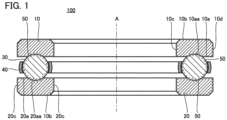
Fig. 1 is a sectional view of a rolling bearing 100. -
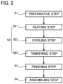
Fig. 2 is a process chart showing a method for producing rolling bearing 100. -
Fig. 3 is a graph showing distribution of contents of carbon and nitrogen in superficial parts of an inner ring and an outer ring of asample 1. -
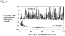
Fig. 4 is a graph showing distribution of contents of carbon and nitrogen in superficial parts of an inner ring and an outer ring of a sample 2. -
Fig. 5 is a representative sectional FE-SEM image in the superficial parts of the inner ring and the outer ring ofsample 1. -
Fig. 6 is a representative sectional FE-SEM image in the superficial parts of the inner ring and the outer ring of sample 2. -
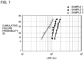
Fig. 7 is a graph showing a rolling fatigue life test result. -
Fig. 8 is a sectional view of aninner ring 210. -
Fig. 9 is an enlarged view in IX inFig. 8 . -
Fig. 10 is a process chart showing a method for producinginner ring 210. -
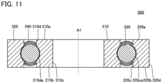
Fig. 11 is a sectional view of a rolling bearing 200. -
Fig. 12 is a graph showing measurement results of nitrogen concentration and carbon concentration in the vicinity of the raceway surface of a washer of asample 4. -
Fig. 13 is a graph showing measurement results of nitrogen concentration and carbon concentration in the vicinity of the raceway surface of a washer of asample 5. -
Fig. 14 is a SEM image in a superficial part of the washer ofsample 4. -
Fig. 15 is a SEM image in a superficial part of the washer ofsample 5. -
Fig. 16 is a phase map of EBSD in the superficial part of the washer ofsample 4. -
Fig. 17 is a phase map of EBSD in the superficial part of the washer ofsample 5. -
Fig. 18 is a phase map of EBSD in a superficial part of a washer of asample 6. -
Fig. 19 is a bar graph showing average grain sizes of martensite block grains in the superficial parts of the washers ofsample 4 tosample 6. -
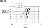
Fig. 20 is a graph showing a result of a rolling fatigue life test. - The details of embodiments of the present invention are described by referring to drawings. In the following drawings, the same or the corresponding part is denoted by the same reference numeral and overlapping description is not repeated.
- Hereinafter, configuration of a rolling bearing according to the first embodiment (hereinafter, referred to as "rolling
bearing 100") is described. Rolling bearing 100 is, for example, a single-direction thrust ball bearing with flat seats. However, rollingbearing 100 is not limited to this. - Rolling bearing 100 is, for example, for use in a transaxle of vehicle (fuel cell vehicle, electric vehicle and the like), for use in a transmission (continuously variable transmission) of vehicle, or for use in a motor (for driving gear, for transmission) of vehicle. Rolling bearing 100 may be for use in a hydrogen pressure reducing valve of fuel cell vehicle or for use in a hydrogen circulator of fuel cell vehicle. Rolling bearing 100 may be for use in electrical equipment of vehicle or for use in an auxiliary machinery of vehicle (alternator, electromagnetic clutch of car air conditioner, fan coupling device, intermediate pulley, electric-powered fan motor, compressor and the like).
- Rolling bearing 100 may be a hub bearing. Rolling bearing 100 may be for use in a machine tool (for main shaft), for use in a wind turbine generator (for speed increasing gear), for use in a railway vehicle (for vehicle shaft, for driving gear, for main motor, etc.), for use in a construction machinery (for axle etc.), for use in a paper machine, or for use in a transmission. However, use application of rolling
bearing 100 is not limited to these. -
Fig. 1 is a sectional view of rollingbearing 100. As shown inFig. 1 , rollingbearing 100 has a central axis A.Fig. 1 shows a sectional view of rollingbearing 100 in a cross section along a central axis A. Rolling bearing 100 has a raceway member (raceway ring or washer), and a rolling element. In rollingbearing 100, the raceway member is an inner ring (shaft washer) 10 and an outer ring (housing washer) 20, and the rolling element is aball 30. Rolling bearing 100 further has aretainer 40. -
Inner ring 10 has an annular (ring-like) shape.Inner ring 10 has afirst face 10a, asecond face 10b, an innercircumferential face 10c, and an outercircumferential face 10d. -
First face 10a andsecond face 10b constitute end faces in the direction along central axis A (hereinafter, referred to as "axial direction").Second face 10b is the opposite face offirst face 10a in the axial direction.First face 10a has a raceway surface 10aa.First face 10a is recessed towardsecond face 10b in raceway surface 10aa. In the sectional view, raceway surface 10aa has a partially arc shape.
Raceway surface 10aa is a surface that comes into contact withball 30, and constitutes a contact surface ofinner ring 10. - Inner
circumferential face 10c is a surface facing to central axis A side. Innercircumferential face 10c connects at one end in the axial direction withfirst face 10a, and connects at the other end in the axial direction withsecond face 10b. - Outer
circumferential face 10d is a surface facing to the side opposite to central axis A. That is, outercircumferential face 10d is an opposite surface of innercircumferential face 10c in the direction orthogonal to central axis A (hereinafter, referred to as "radial direction"). Outercircumferential face 10d connects at one end in the axial direction withfirst face 10a, and connects at the other end in the axial direction withsecond face 10b. -
Outer ring 20 has a ring-like shape.Outer ring 20 has afirst face 20a, a second face 20b, an innercircumferential face 20c and an outer circumferential face 20d. -
First face 20a and second face 20b constitute end faces in the axial direction.Outer ring 20 is arranged such thatfirst face 20a faces withfirst face 10a. Second face 20b is the opposite face offirst face 20a in the axial direction.First face 20a has a raceway surface 20aa.First face 20a is recessed toward second face 20b in raceway surface 20aa. In the sectional view, raceway surface 20aa has a partially arc shape. Raceway surface 20aa is a surface that comes into contact withball 30, and constitutes a contact surface ofouter ring 20. - Inner
circumferential face 20c is a surface facing to central axis A side. Innercircumferential face 20c connects at one end in the axial direction withfirst face 20a, and connects at the other end in the axial direction with second face 20b. - Outer circumferential face 20d is a surface facing to the side opposite to central axis A. That is, outer circumferential face 20d is an opposite surface of inner
circumferential face 20c in the direction orthogonal to central axis A (hereinafter, referred to as "radial direction"). Outer circumferential face 20d connects at one end in the axial direction withfirst face 20a, and connects at the other end in the axial direction with second face 20b. -
Ball 30 has a globular shape. There are a plurality ofballs 30.Ball 30 is arranged betweenfirst face 10a andfirst face 20a. More specifically,ball 30 is arranged between raceway surface 10aa and raceway surface 20aa.Ball 30 comes into contact with raceway surface 10aa and raceway surface 20aa on the surface ofball 30. That is, the surface ofball 30 is a contact surface. -
Retainer 40 retainsball 30.Retainer 40 retainsball 30 such that an interval of two neighboringballs 30 falls within a certain range in the direction along the circumference about central axis A (hereinafter, referred to as "circumferential direction"). -
Inner ring 10,outer ring 20 andball 30 are formed of steel having a composition shown in Table 1 (hereinafter, referred to as "first composition").Inner ring 10,outer ring 20 andball 30 may be formed of steel having a composition shown in Table 2 (hereinafter, referred to as "second composition"). Steel that formsinner ring 10,outer ring 20 andball 30 is quenched. It is only required that at least one ofinner ring 10,outer ring 20 orball 30 is formed of steel of the first composition (second composition). -
Table 1 C Si Mn Cr Mo V Remainder Greater than or equal to 0.70 and less than or equal to 1.10 Greater than or equal to 0.15 and less than or equal to 0.35 Greater than or equal to 0.30 and less than or equal to 0.60 Greater than or equal to 1.30 and less than or equal to 1.60 Greater than or equal to 0.01 and less than or equal to 0.50 Greater than or equal to 0.01 and less than or equal to 0.50 Fe and inevitable impurity Unit: mass% -
Table 2 C Si Mn Cr Mo V Remainder Greater than or equal to 0.90 and less than or equal to 1.10 Greater than or equal to 0.20 and less than or equal to 0.30 Greater than or equal to 0.40 and less than or equal to 0.50 Greater than or equal to 1.40 and less than or equal to 1.60 Greater than or equal to 0.20 and less than or equal to 0.30 Greater than or equal to 0.20 and less than or equal to 0.30 Fe and inevitable impurity Unit: mass% - Carbon (C) influences on the hardness of the contact surface (raceway surface 10aa, raceway surface 20aa and surface of ball 30) after quenching. If the content of carbon in steel is less than 0.70 mass%, it is difficult to secure sufficient hardness in the contact surface. Also, if the content of carbon in steel is less than 0.70 mass%, it is necessary to supplement the carbon content in the surface by a carburizing treatment or the like. This results in deterioration in production efficiency and increase in production cost. If the content of carbon in steel is greater than 1.10 mass%, a crack at the time of quenching (quenching crack) can be generated. Therefore, in the steel of the first composition, the content of carbon is set to be greater than or equal to 0.70 mass% and less than or equal to 1.10 mass%.
- Silicon is added for deoxidation at the time of refining of steel and securement of workability before a nitriding treatment. If the content of silicon in steel is less than 0.15 mass%, resistance to temper softening is insufficient. As a result, hardness of the contact surface can deteriorate due to temperature rise at the time of tempering after quenching or during use of rolling
bearing 100. If the content of silicon in steel is greater than 0.35 mass%, the steel is too hard, and the tool life of the cutting tool used in machining inner ring 10 (outer ring 20, ball 30) can be shortened. Also, in this case, the material cost of steel increases. Therefore, in the steel of the first composition, the content of silicon is set to be greater than or equal to 0.15 mass% and less than or equal to 0.35 mass%. - Manganese is added to secure the hardenability and hardness of steel. If the content of manganese in steel is less than 0.30 mass%, it is difficult to secure the hardenability and the hardness of steel. If the content of manganese in steel is greater than 0.60 mass%, the steel is too hard, and the tool life of the cutting tool used in machining inner ring 10 (
outer ring 20, ball 30) can be shortened. Also, in this case, the material cost of steel increases. Therefore, in the steel of the first composition, the content of manganese is set to be greater than or equal to 0.30 mass% and less than or equal to 0.60 mass%. - Chromium is added to secure the hardenability of steel, and to secure the hardness by forming fine precipitates in association with a nitriding treatment. If the content of chromium in steel is less than 1.30 mass%, it is difficult to secure the hardenability and the hardness of steel. If the content of chromium in steel is greater than 1.60 mass%, precipitates become coarse, and can be an origin of a fatigue failure. Also, in this case, the material cost of steel increases. Therefore, in the steel of the first composition, the content of chromium is set to be greater than or equal to 1.30 mass% and less than or equal to 1.60 mass%.
- Molybdenum is added to secure the hardenability of steel, and to secure the hardness by forming fine precipitates in association with a nitriding treatment. Since molybdenum has strong affinity with carbon, it precipitates as undissolved carbide in steel at the time of a nitriding treatment. Since the undissolved carbide of molybdenum serves as a precipitation core at the time of quenching, molybdenum increases the quantity of precipitates after quenching.
- If the content of molybdenum in steel is less than 0.01 mass%, it is difficult to secure the hardenability and the hardness of steel. If the content of molybdenum in steel is greater than 0.50 mass%, precipitates become coarse, and can be an origin of a fatigue failure. In this case, the material cost of steel also increases. Therefore, in the steel of the first composition, the content of molybdenum is set to be greater than or equal to 0.01 mass% and less than or equal to 0.50 mass%.
- Vanadium is added to secure the hardenability of steel, and to secure the hardness by forming fine precipitates in association with a nitriding treatment. If the content of vanadium in steel is less than 0.01 mass%, it is difficult to secure the hardenability and the hardness of steel. If the content of vanadium in steel is greater than 0.50 mass%, precipitates become coarse, and can be an origin of a fatigue failure. In this case, the material cost of steel also increases. Therefore, in the steel of the first composition, the content of vanadium is set to be greater than or equal to 0.01 mass% and less than or equal to 0.50 mass%.
- As shown in
Fig. 1 ,inner ring 10,outer ring 20 andball 30 have asuperficial part 50 in their surfaces.Superficial part 50 is a region up to a depth of 20 µm from the surface ofinner ring 10,outer ring 20 andball 30. It is only required thatsuperficial part 50 is formed in the contact surface of at leastinner ring 10,outer ring 20 andball 30. Also, it is only required thatsuperficial part 50 is formed in at least one ofinner ring 10,outer ring 20 orball 30. -
Superficial part 50 is a part formed by a nitriding treatment. The content of nitrogen insuperficial part 50 is greater than or equal to 0.2 mass% and less than or equal to 0.8 mass%. If the content of nitrogen insuperficial part 50 is less than 0.2 mass%, it is difficult to secure the durability of the contact surface. If the content of nitrogen insuperficial part 50 is greater than 0.8 mass%, the time required for the nitriding treatment elongates, and the production cost increases. Therefore, the content of nitrogen insuperficial part 50 is set to be greater than or equal to 0.2 mass% and less than or equal to 0.8 mass%. It is preferred that the content of nitrogen insuperficial part 50 is greater than or equal to 0.3 mass% and less than or equal to 0.5 mass%. - The content of nitrogen in
superficial part 50 is measured by an electron probe micro analyzer (EPMA). - In the sectional view orthogonal to the contact surface, it is preferred that a total of greater than or equal to 60 precipitates having a grain size of less than or equal to 0.5 µm exist per 100 µm2 in
superficial part 50. In the sectional view orthogonal to the contact surface, it is further preferred that a total of greater than or equal to 80 precipitates having a grain size of less than or equal to 0.5 µm exist per 100 µm2 insuperficial part 50. - In the sectional view orthogonal to the contact surface, it is preferred that a total of area fractions of precipitates in
superficial part 50 is greater than or equal to 1% and less than or equal to 10%. In the sectional view orthogonal to the contact surface, it is further preferred that a total of area fractions of precipitates insuperficial part 50 is greater than or equal to 2% and less than or equal to 7%. - Precipitates in
superficial part 50 are, for example, carbonitrides and nitrides. Carbonitrides include carbides of iron, carbides of iron in which carbon is substituted by nitrogen, and carbides of iron in which iron is substituted by an alloy element other than iron. Nitrides are nitrides of iron. Precipitates insuperficial part 50 may be carbides, carbonitrides or nitrides of an alloy element contained in steel. - Precipitates in steel of
superficial part 50 may be nitride based on chromium or vanadium, or carbonitride based on chromium or vanadium. - Nitride based on chromium (vanadium) is nitride of chromium (vanadium) or nitrides of chromium (vanadium) in which part chromium (vanadium) sites is substituted by an alloy element other than chromium (vanadium).
- Carbonitrides based on chromium (vanadium) are carbides of chromium (vanadium) in which part of carbon sites is substituted by nitrogen. A chromium (vanadium) site in carbonitride based on chromium (vanadium) may be substituted by an alloy element other than chromium (vanadium).
- An area fraction of precipitate is calculated by acquiring a sectional image of
superficial part 50 at a magnification of 5000 times using a Field Emission Scanning Electron Microscope (FE-SEM), binarizing the sectional image, and conducting an image processing for the binarized sectional image. The sectional image ofsuperficial part 50 is acquired in greater than or equal to three fields of view, and the area fraction is an average value of the plurality of sectional images. - A grain size of each precipitate is obtained by acquiring an area of each precipitate in the same manner as described above, and multiplying a square root of the value obtained by dividing the acquired area by π, by 2.
- It is preferred that a volume fraction of retained austenite in steel that forms
inner ring 10,outer ring 20 andball 30 is greater than or equal to 20% and less than or equal to 40% at a position of 50 µm deep from the contact surface. As a result, it is possible to improve the durability of the contact surface (especially, durability of the contact surface under a contaminated environment). If the volume fraction of retained austenite is less than 25%, the durability of the contact surface can be insufficient. If the volume fraction of retained austenite is greater than 35%, there is a fear for aged deterioration in association with decomposition of retained austenite. - It is further preferred that a volume ratio of retained austenite in steel that forms
inner ring 10,outer ring 20 andball 30 is greater than or equal to 25% and less than or equal to 35% at a position of 50 µm deep from the contact surface. - A retained austenite quantity in steel at a position of 50 µm deep from the contact surface is measured by an X-ray diffraction method. More specifically, a retained austenite quantity in steel at a position of 50 µm deep from the contact surface is measured by using an MSF-3M available from Rigaku Corporation.
- It is preferred that hardness at a position where the depth from the contact surface of
inner ring 10,outer ring 20 andball 30 is to be 50 µm is greater than or equal to 653 Hv and less than or equal to 800 Hv. If the hardness at a position where the depth from the contact surface is to be 50 µm is less than 653 Hv, durability of the contact surface can be insufficient. On the other hand, if hardness at a position where the depth from the contact surface is to be 50 µm is greater than 800 Hv, ductility and tenacity can deteriorate and early damage can be generated. - Hardness at a position where the depth from the contact surface of
inner ring 10,outer ring 20 andball 30 is to be 50 µm is measured by a Vickers hardness test method defined in JIS standard (JIS Z 2244:2009). The load at the time of measurement is set at 300 gf. - Steel of
superficial part 50 has martensite block grains. Neighboring two martensite block grains have a difference in crystal orientation in the grain boundary of greater than or equal to 15°. From another perspective, even if there is a location where crystal orientation deviates, the location is not regarded as a crystal grain boundary of martensite block grains as long as the difference in crystal orientation is less than 15°. A grain boundary of martensite block grains is determined by an EBSD (Electron Back Scattered Diffraction) method. - In steel of
superficial part 50, an average grain size of martensite block grains at a comparison area fraction of 30% is less than or equal to 2.0 µm. In steel ofsuperficial part 50, it is preferred that an average grain size of martensite block grains at a comparison area fraction of 50% is less than or equal to 1.5 µm. - An average grain size of martensite block grains at a comparison area fraction of 30% (50%) is measured in the following method. First, in a cross section of
inner ring 10 includingsuperficial part 50, the cross section is observed. At this time, by the EBSD method, martensite block grains contained in the observation field are determined. This observation field is a region of 50 µm × 35 µm. Second, from the crystal orientation data obtained by the EBSD method, respective areas of the martensite block grains contained in the observation field are analyzed. - Third, respective areas of the martensite block grains contained in the observation field are added up in descending order of area. The addition is performed until the 30% (50%) of the total area of the martensite block grains contained in the observation field is reached. For each of the martensite block grains that are objects of the addition, an equivalent circle diameter is calculated. The equivalent circle diameter is a square root of a value obtained by dividing the area of the martensite block grain by π/4. An average value of equivalent circle diameters of martensite block grains that are objects of the addition is regarded as an average grain size of martensite block grains at a comparison area fraction of 30% (50%).
- Hereinafter, a method for producing a rolling bearing is described.
-
Fig. 2 is a process chart showing a method for producing rollingbearing 100. As shown inFig. 2 , the method for producing rollingbearing 100 has a preparative step S1, a heat treatment step S2, a finishing step S3, and an assembling step S4. Heat treatment step S2 is conducted after preparative step S1. Finishing step S3 is conducted after heat treatment step S2. Assembling step S4 is conducted after finishing step S3. - In preparative step S1, a workpiece to be subjected to heat treatment step S2 and finishing step S3 is prepared. As the workpiece, a ring-shaped member is prepared when
inner ring 10 andouter ring 20 are intended to be formed, and a globular member is prepared whenball 30 is intended to be formed. The workpiece is formed of steel having a first composition or a second composition. - Heat treatment step S2 has a heating step S21, a cooling step S22, and a tempering step S23. In heating step S21, the workpiece is retained at a temperature of greater than or equal to A1 transformation point for a predetermined time. In heating step S21, a nitriding treatment for the workpiece is also conducted. The nitriding treatment is performed by conducting the heating and retaining in the atmospheric gas containing a gas that is a source of nitrogen (for example, ammonia gas).
- Cooling step S22 is conducted after heating step S21. In cooling step S22, the workpiece is cooled to a temperature of less than or equal to Ms transformation point. The cooling is carried out, for example, by oil cooling. The tempering step S23 is conducted after cooling step S22. In tempering step S23, the workpiece is retained at a temperature of less than A1 transformation point for a predetermined time.
- In finishing step S3, finishing (grinding, polishing) and washing are conducted for the workpiece. In this manner,
inner ring 10,outer ring 20 andball 30 are prepared. In assembling step S4,inner ring 10,outer ring 20 andball 30 are assembled together withretainer 40. Thus, rollingbearing 100 having the structure shown inFig. 1 is produced. - Hereinafter, an effect of rolling
bearing 100 is described. - In rolling
bearing 100, sincesuperficial part 50 having subjected to a nitriding treatment is formed in the contact surface ofinner ring 10,outer ring 20 andball 30, a damage such as crack is difficult to be generated in the contact surface (and directly under the contact surface). Also, in rollingbearing 100, sinceinner ring 10,outer ring 20 andball 30 are formed of steel having the first composition or the second composition, the hardness in the contact surface (and directly under the contact surface) can be secured, for example, by precipitation of fine precipitates insuperficial part 50, and the precipitates can be prevented from becoming a stress concentration source (becoming an origin of generation of a crack). - In rolling
bearing 100, since fine precipitates precipitate insuperficial part 50, and the hardness of the contact surface is secured, formation of newly generated metal surface in the contact surface is prevented. Therefore, in rollingbearing 100, hydrogen is difficult to be generated in the contact surface. Also, in rollingbearing 100, a fine precipitate precipitates insuperficial part 50, and the vicinity of the precipitate serves as a trap site of hydrogen, so that the hydrogen penetration quantity insuperficial part 50 decreases. Therefore, in rollingbearing 100, an early flaking damage caused by hydrogen brittleness is difficult to occur. In this manner, according to rollingbearing 100, it is possible to elongate the life of the rolling bearing. - In steel of
superficial part 50, when the martensite block grains are fined so that the average grain size at a comparison area fraction of 30% is less than or equal to 2.0 µm, the shear resistance of the contact surface (specifically, raceway surface 10da, raceway surface 20ca and surface of ball 30) is improved by increased toughness of thesuperficial part 50. Therefore, in this case, the durability of rollingbearing 100 can be further improved. - Hereinafter, Examples of rolling
bearing 100 are described. - As samples of rolling bearing, a
sample 1, a sample 2 and asample 3 were prepared.Sample 1, sample 2 andsample 3 are single-direction thrust ball bearings of the model number 51106 in JIS standard having an inner diameter of 30 mm, an outer diameter of 47 mm and a width of 11 mm. - The inner ring and the outer ring of
sample 1 were formed of steel having a composition shown in Table 3. The composition shown in Table 3 falls in the ranges of the first composition and the second composition. The inner ring and the outer ring of sample 2, and the inner ring and the outer ring ofsample 3 were formed of steel having a composition shown in Table 4. The composition shown in Table 4 falls in the composition of SUJ2 defined in JIS standard, and falls outside the ranges of the first composition and the second composition. Balls ofsample 1, sample 2 andsample 3 were formed of stainless steel (SUS440C). -
Table 3 C Si Mn Cr Mo V Remainder 1.00 0.26 0.44 1.51 0.24 0.24 Fe and inevitable impurity Unit: mass% -
Table 4 C Si Mn Cr Mo V Remainder 0.99 0.26 0.44 1.51 0.00 0.00 Fe and inevitable impurity Unit: mass% - The inner ring and the outer ring of
sample 1, and the inner ring and the outer ring of sample 2 were subjected to heat treatment step S2. The inner ring and the outer ring ofsample 3 are not subjected to heat treatment step S2. More specifically, for the inner ring and the outer ring ofsample 3, quenching and tempering are conducted, however, nitriding treatment is not conducted. -
Fig. 3 is a graph showing distribution of contents of carbon and nitrogen in superficial parts of the inner ring and the outer ring ofsample 1.Fig. 4 is a graph showing distribution of contents of carbon and nitrogen in superficial parts of the inner ring and the outer ring of sample 2. InFig. 3 andFig. 4 , the horizontal axis indicates a distance from the surface (unit: mm), and the vertical axis indicates contents of carbon and nitrogen (unit: mass%). As shown inFig. 3 ,Fig. 4 and Table 5, contents of nitrogen in the superficial parts in the inner ring and the outer ring ofsample 1 and in the inner ring and the outer ring of sample 2 were greater than or equal to 0.3 mass% and less than or equal to 0.5 mass%. On the other hand, as shown in Table 5, contents of nitrogen in the superficial parts in the inner ring and the outer ring ofsample 3 were 0 mass% (nitrogen was not contained). - As shown in Table 5, in the superficial parts in the inner ring and the outer ring of
sample 1, a total of area fractions of precipitates was greater than or equal to 2.2% and less than or equal to 7.0%. In the superficial parts in the inner ring and the outer ring of sample 2, a total of area fractions of precipitates was greater than or equal to 1.2% and less than or equal to 4.0%. In the superficial parts in the inner ring and the outer ring ofsample 3, a total of area fractions of precipitates was greater than or equal to 0.07% and less than or equal to 0.24%. - As shown in Table 5, in the superficial parts in the inner ring and the outer ring of
sample 1, the number of precipitates was greater than or equal to 66 and less than or equal to 425 in total per 100 µm2. In the superficial parts in the inner ring and the outer ring of sample 2, the number of precipitates was greater than or equal to 29 and less than or equal to 81 in total per 100 µm2. In the superficial parts in the inner ring and the outer ring ofsample 3, the number of precipitates was greater than or equal to 8 and less than or equal to 50 in total per 100 µm2. -
Table 5 Content of nitrogen in superficial part (mass%) Area fraction of precipitate (%) Number of precipitates per 100 µm2 (number) Inner ring and outer ring of sample 1Greater than or equal to 0.3 and less than or equal to 0.5 Greater than or equal to 2.2 and less than or equal to 7.0 Greater than or equal to 66 and less than or equal to 425 Inner ring and outer ring of sample 2 Greater than or equal to 0.3 and less than or equal to 0.5 Greater than or equal to 1.2 and less than or equal to 4.0 Greater than or equal to 29 and less than or equal to 81 Inner ring and outer ring of sample 30 Greater than or equal to 0.07 and less than or equal to 0.24 Greater than or equal to 8 and less than or equal to 50 -
Fig. 5 is a representative sectional FE-SEM image in the superficial parts of the inner ring and the outer ring ofsample 1.Fig. 6 is a representative sectional FE-SEM image in the superficial parts of the inner ring and the outer ring of sample 2. As shown inFig. 5 , in the superficial parts of the inner ring and the outer ring ofsample 1, precipitates were fined (most of precipitates had a grain size of less than or equal to 0.5 µm). On the other hand, as shown inFig. 6 , in the superficial parts of the inner ring and the outer ring of sample 2, precipitates were not fined (most of precipitates had a grain size of greater than 0.5 µm). - As shown in Table 6, a volume ratio of retained austenite at a position where the depth from the contact surface of the inner ring and the outer ring of
sample 1 is to be 50 µm was greater than or equal to 29.8% and less than or equal to 30.8%. A volume ratio of retained austenite at a position where the depth from the contact surface of the inner ring and the outer ring of sample 2 is to be of 50 µm was greater than or equal to 30.2% and less than or equal to 31.4%. A volume ratio of retained austenite at a position where the depth from the contact surface of the inner ring and the outer ring ofsample 3 is to be of 50 µm was greater than or equal to 9.7% and less than or equal to 11.5%. - As shown in Table 6, hardness at a position where the depth from the contact surface of the inner ring and the outer ring of
sample 1 is to be 50 µm was greater than or equal to 755 Hv and less than or equal to 759 Hv. Hardness at a position where the depth from the contact surface of the inner ring and the outer ring of sample 2 is to be 50 µm was greater than or equal to 749 Hv and less than or equal to 758 Hv.
Hardness at a position where the depth from the contact surface of the inner ring and the outer ring ofsample 3 is to be 50 µm was greater than or equal to 735 Hv and less than or equal to 765 Hv. -
Table 6 Volume fraction of retained austenite at position of 50 µm deep from contact surface (%) Hardness at position of 50 µm deep from contact surface (Hv) Inner ring and outer ring of sample 1Greater than or equal to 29.8 and less than or equal to 30.8 Greater than or equal to 755 and less than or equal to 759 Inner ring and outer ring of sample 2 Greater than or equal to 30.2 and less than or equal to 31.4 Greater than or equal to 749 and less than or equal to 758 Inner ring and outer ring of sample 3Greater than or equal to 9.7 and less than or equal to 11.5 Greater than or equal to 735 and less than or equal to 765 - A rolling fatigue life test was conducted for
sample 1, sample 2 andsample 3. As shown in Table 7, the rolling fatigue life test was conducted under the conditions of a maximum contact surface pressure of 2.3 GPa, rapid acceleration and deceleration between 0 rpm (revolutions per minute) and 2500 rpm, and lubrication with a mixture of polyglycol and pure water. -
Fig. 7 is a graph showing a rolling fatigue life test result. InFig. 7 , the horizontal axis indicates life (unit: hr), and the vertical axis indicates cumulative failure probability (unit: %). As shown inFig. 7 and Table 7, comparison in L10 life (the time at which the cumulative failure probability reaches 10%) revealed that the rolling fatigue life of sample 2 was longer than the rolling fatigue life ofsample 3. The comparison result experimentally demonstrated that the rolling fatigue life is improved by performing a nitriding treatment so that the content of nitrogen insuperficial part 50 is greater than or equal to 0.2 mass% and less than or equal to 0.8 mass%. - As shown in
Fig. 7 and Table 7, comparison in L10 life revealed that the rolling fatigue life ofsample 1 was longer than the rolling fatigue life of sample 2. The comparison result experimentally demonstrated that by forming at least one ofinner ring 10,outer ring 20 orball 30 of steel having the first composition, precipitates are finely dispersed insuperficial part 50, and the rolling fatigue life is improved. -
Table 7 L10 life Sample 1 2.7 times as compared with sample 3Sample 2 2.1 times as compared with sample 3 - Hydrogen penetration property into superficial parts of raceway members (inner ring and outer ring) of
sample 1 andsample 3 was evaluated by the following method. In this evaluation, first, by heating raceway members ofsample 1 andsample 3 before being subjected to the rolling fatigue life test to 400°C from the room temperature, hydrogen release amounts from the raceway members ofsample 1 andsample 3 before being subjected to the rolling fatigue life test were measured. Secondly, by heating raceway members ofsample 1 andsample 3 after being subjected to the rolling fatigue life test for 50 hours to 400°C from the room temperature, hydrogen release amounts from the raceway members ofsample 1 andsample 3 after being subjected to the rolling fatigue life test for 50 hours were measured. - In
sample 3, the ratio of hydrogen release amount before and after the rolling fatigue life test (namely, the value obtained by dividing the hydrogen release amount after being subjected to the rolling fatigue life test by the hydrogen release amount before being subjected to the rolling fatigue life test) was 3.2. On the other hand, insample 1, the ratio of hydrogen release amount before and after the rolling fatigue life test was 0.9. This comparison experimentally revealed that by formation ofsuperficial part 50 in the contact surface, penetration of hydrogen intosuperficial part 50 is prevented, and early flaking caused by hydrogen brittleness is prevented. - A bearing component according to the second embodiment is, for example, an
inner ring 210 of a rolling bearing. Hereinafter,inner ring 210 is described as an example of a bearing component according to the second embodiment. However, the bearing component according to the second embodiment is not limited to this. The bearing component according to the second embodiment may be an outer ring of a rolling bearing or a rolling element of a rolling bearing. -
Fig. 8 is a sectional view ofinner ring 210. As shown inFig. 8 ,inner ring 210 is ring-shaped. The central axis ofinner ring 210 is named a central axis A1.Inner ring 210 has awidth face 210a, awidth face 210b, an innercircumferential face 210c, and an outercircumferential face 210d.Width face 210a,width face 210b, innercircumferential face 210c and outercircumferential face 210d constitute the surface ofinner ring 210. - In the following, the direction of central axis A1 is referred to as an axial direction. Also, in the following, the direction along the circumference about central axis A1 when viewed along the axial direction is referred to as a circumferential direction. Further, in the following, the direction orthogonal to the axial direction is referred to as a radial direction.
-
Width face 210a andwidth face 210b are end faces ofinner ring 210 in the axial direction.Width face 210b is an opposite face ofwidth face 210a in the axial direction. - Inner
circumferential face 210c extends in the circumferential direction. Innercircumferential face 210c faces central axis A1 side. Innercircumferential face 210c connects at one end in the axial direction withwidth face 210a, and connects at the other end in the axial direction withwidth face 210b.Inner ring 210 is fitted with a shaft (not shown) in innercircumferential face 210c. - Outer
circumferential face 210d extends in the circumferential direction. Outercircumferential face 210d faces opposite side of central axis A1. That is, outercircumferential face 210d is an opposite face of innercircumferential face 210c in the radial direction. Outercircumferential face 210d connects at one end in the axial direction withwidth face 210a, and connects at the other end in the axial direction withwidth face 210b. - Outer
circumferential face 210d has a raceway surface 210da. Raceway surface 210da extends in the circumferential direction. Outercircumferential face 210d is recessed toward innercircumferential face 210c in raceway surface 210da. In the sectional view, raceway surface 210da has a partially circular shape. Raceway surface 210da is located in the center of outercircumferential face 210d in the axial direction. Raceway surface 210da is part of outercircumferential face 210d that comes into contact with a rolling element (not shown inFig. 1 ). -
Inner ring 210 is formed of steel. More specifically,inner ring 210 is formed of steel having been quenched and tempered. Steel that formsinner ring 210 contains carbon of greater than or equal to 0.70 mass% and less than or equal to 1.10 mass%, silicon of greater than or equal to 0.15 mass% and less than or equal to 0.35 mass%, manganese of greater than or equal to 0.30 mass% and less than or equal to 0.60 mass%, chromium of greater than or equal to 1.30 mass% and less than or equal to 1.60 mass%, vanadium of less than or equal to 0.50 mass% and molybdenum of less than or equal to 0.50 mass%. In the steel, the content of molybdenum is greater than or equal to 0.01 mass%, and the content of vanadium is greater than or equal to 0.01 mass%. - Carbon in steel that forms
inner ring 210 is greater than or equal to 0.70 mass% so as to improve the hardness. Carbon in steel that formsinner ring 210 is less than or equal to 1.10 mass% so as to prevent a quenching crack. - Silicon in steel that forms
inner ring 210 is greater than or equal to 0.15 mass% so as to enhance the resistance to temper softening and improve the workability. Silicon in steel that formsinner ring 210 is less than or equal to 0.35 mass% because an excessive quantity of silicon contrarily deteriorates the workability. - Manganese in steel that forms
inner ring 210 is greater than or equal to 0.30 mass% so as to secure the hardenability. Manganese in steel that formsinner ring 210 is less than or equal to 0.60 mass% because an excessive quantity of manganese results in increase in a manganese-based non-metallic inclusion in the steel. - Chromium in steel that forms
inner ring 210 is greater than or equal to 1.30 mass% so as to secure the hardenability and form nitride and carbonitride. Chromium in steel that formsinner ring 210 is less than or equal to 1.60 mass% so as to prevent formation of a coarse precipitate. - Steel that forms
inner ring 210 contains vanadium so as to fine nitride and carbonitride. Vanadium in steel that formsinner ring 210 is less than or equal to 0.50 mass% so as to prevent increase in cost due to addition of vanadium. - Steel that forms
inner ring 210 contains molybdenum so as to fine nitride and carbonitride, and improve the hardenability. Molybdenum in steel that formsinner ring 210 is less than or equal to 0.50 mass% so as to prevent increase in cost due to addition of molybdenum. - Steel that forms
inner ring 210 may contain carbon of greater than or equal to 0.90 mass% and less than or equal to 1.10 mass%, silicon of greater than or equal to 0.20 mass% and less than or equal to 0.30 mass%, manganese of greater than or equal to 0.40 mass% and less than or equal to 0.50 mass%, chromium of greater than or equal to 1.40 mass% and less than or equal to 1.60 mass%, vanadium of greater than or equal to 0.20 mass% and less than or equal to 0.30 mass% and molybdenum of greater than or equal to 0.10 mass% and less than or equal to 0.30 mass%. The remainder of steel that formsinner ring 210 is iron and inevitable impurities. -
Fig. 9 is an enlarged view in IX inFig. 8 . As shown inFig. 9 , ininner ring 210, the region up to a distance of 20 µm from the surface is asuperficial part 211. The surface ofinner ring 210 has been subjected to, for example, a nitriding treatment. As a result, nitrogen concentration in steel ofsuperficial part 211 is, for example, greater than or equal to 0.15 mass%. It is preferred that nitrogen concentration in steel ofsuperficial part 211 is greater than or equal to 0.20 mass% and less than or equal to 0.30 mass%. Nitrogen concentration in steel ofsuperficial part 211 is measured with an EPMA (Electron Probe Micro Analyzer). - In steel of
superficial part 211, precipitates are dispersed. Precipitates are nitride based on chromium or vanadium, or carbonitride based on chromium or vanadium. - Nitride based on chromium (vanadium) is nitride of chromium (vanadium) or nitrides of chromium (vanadium) in which part chromium (vanadium) sites is substituted by an alloy element other than chromium (vanadium).
- Carbonitrides based on chromium (vanadium) are carbides of chromium (vanadium) in which part of carbon sites is substituted by nitrogen. A chromium (vanadium) site in carbonitride based on chromium (vanadium) may be substituted by an alloy element other than chromium (vanadium).
- It is preferred that the area fraction of precipitate in steel of
superficial part 211 is less than or equal to 2.0%. It is preferred that the maximum grain size of precipitate in steel ofsuperficial part 211 is less than or equal to 0.5 µm. - The area fraction and the maximum grain size of precipitate in steel of
superficial part 211 are measured in the following method. First, in a cross section ofinner ring 210 includingsuperficial part 211, a sectional image (hereinafter, referred to as "SEM image") is acquired using SEM (Scanning Electron Microscope). The magnification at the time of acquiring the SEM image is 15000 times. - Second, the acquired SEM image is subjected to an image processing. More specifically, since precipitates appear in white in the SEM image, an area of each part that appears in white in the SEM image and the total area are calculated by the image processing.
- The total area of the parts that appear in white in the SEM image is regarded as an area fraction of precipitate in steel of
superficial part 211. The square root of the value obtained by dividing the maximum value of areas of parts that appear in white in the SEM image by π/4 is regarded as a maximum grain size of precipitates in steel ofsuperficial part 211. - In steel of
superficial part 211, cementite (Fe3C) may further be dispersed. Part of iron sites in cementite may be substituted by an alloy element, and part of carbon sites in cementite may be substituted by nitrogen. It is preferred that the maximum grain size of cementite in steel ofsuperficial part 211 is less than or equal to 1.5 µm. - The maximum grain size of cementite in steel of
superficial part 211 is measured in the following method. First, in a cross section ofinner ring 210 includingsuperficial part 211, a SEM image is acquired. The magnification at the time of acquiring the SEM image is 15000 times. Second, the acquired SEM image is subjected to an image processing. More specifically, since cementite appears in a gray oval in the SEM image, areas of parts that appear in gray ovals in the SEM image are calculated by the image processing. Then, the square root of the value obtained by dividing the maximum value of areas of parts that in gray ovals in the SEM image by π/4 is regarded as the maximum grain size of cementite in steel ofsuperficial part 211. - It is preferred that a volume ratio of retained austenite in steel is greater than or equal to 15% at a position where the distance from the surface of
inner ring 210 is to be 50 µm. It is further preferred that a volume ratio of retained austenite in steel is greater than or equal to 25% and less than or equal to 35% at a position where the distance from the surface ofinner ring 210 is to be 50 µm. - The volume ratio of retained austenite in steel is measured by an X-ray diffraction method. That is, by comparing the integrated intensity of diffraction peaks in X-ray diffraction of austenite, and integrated intensity of diffraction peaks in X-ray diffraction of phases other than austenite, the volume ratio of retained austenite in steel is calculated.
- It is preferred that hardness of steel is greater than or equal to 58 HRC at a position where the distance from the surface of
inner ring 210 is to be 50 µm. It is further preferred that hardness of steel is greater than or equal to 58 HRC and less than or equal to 64 HRC at a position where the distance from the surface ofinner ring 210 is to be 50 µm. Hardness of steel is measured in accordance with the Rockwell hardness test method defined in JIS standard (JIS Z 2245:2016). - Steel of
superficial part 211 has martensite block grains. Neighboring two martensite block grains have a difference in crystal orientation in the grain boundary of greater than or equal to 15°. From another perspective, even if there is a location where crystal orientation deviates, the location is not regarded as a crystal grain boundary of martensite block grains as long as the difference in crystal orientation is less than 15°. A grain boundary of martensite block grains is determined by an EBSD (Electron Back Scattered Diffraction) method. - In steel of
superficial part 211, the maximum grain size of martensite block grains is less than or equal to 5.0 µm. The maximum grain size of martensite block in steel ofsuperficial part 211 is measured in the following method. - First, in a cross section of
inner ring 210 includingsuperficial part 211, the cross section is observed. At this time, by the EBSD method, martensite block grains contained in the observation field are determined. This observation field is a region of 50 µm × 35 µm. Second, from the crystal orientation data obtained by the EBSD method, respective areas of the martensite block grains contained in the observation field are analyzed. A square root of the value obtained by dividing the maximum value of respective areas of martensite block grains contained in the observation field by π/4 is regarded as the maximum grain size of martensite block in steel ofsuperficial part 211. - In steel of
superficial part 211, it is preferred that an average grain size of martensite block grains at a comparison area fraction of 30% is less than or equal to 2.0 µm. In steel ofsuperficial part 211, it is preferred that an average grain size of martensite block grains at a comparison area fraction of 50% is less than or equal to 1.5 µm. - An average grain size of martensite block grains at a comparison area fraction of 30% (50%) is measured in the following method. First, in a cross section of
inner ring 210 includingsuperficial part 211, the cross section is observed. At this time, by the EBSD method, martensite block grains contained in the observation field are determined. This observation field is a region of 50 µm × 35 µm. Second, from the crystal orientation data obtained by the EBSD method, respective areas of the martensite block grains contained in the observation field are analyzed. - Third, respective areas of the martensite block grains contained in the observation field are added up in descending order of area. The addition is performed until the 30% (50%) of the total area of the martensite block grains contained in the observation field is reached. For each of the martensite block grains that are objects of the addition, an equivalent circle diameter is calculated. The equivalent circle diameter is a square root of a value obtained by dividing the area of the martensite block grain by π/4. An average value of equivalent circle diameters of martensite block grains that are objects of the addition is regarded as an average grain size of martensite block grains at a comparison area fraction of 30% (50%).
- In steel of
superficial part 211, the maximum value of crystal orientation density of {011} plane of martensite block grains is less than or equal to 3.25-fold random. The maximum value of crystal orientation density of {011} plane of martensite block grains in steel ofsuperficial part 211 is determined in the following method. - First, in a cross section of
inner ring 210 includingsuperficial part 211, the cross section is observed. At this time, by the EBSD method, martensite block grains contained in the observation field are determined. This observation field is a region of 50 µm × 35 µm. Second, from the crystal orientation data obtained by the EBSD method, crystal orientation density distribution of {011} plane of martensite block grains is analyzed according to a method described in H.J. Bunge, Mathematische Methoden der Texturanalyse, Akademie-Verlag (1969) using spherical surface harmonics. The highest value of crystal orientation density in the crystal orientation density distribution is regarded as the maximum value of crystal orientation density of {011} plane. - The smaller the maximum value of crystal orientation density of {011} plane of martensite block grains in steel of
superficial part 211, the higher the randomness of formation orientation of {011} plane of martensite block grains in steel ofsuperficial part 211. -
Fig. 10 is a process chart showing a method for producinginner ring 210. As shown inFig. 10 , the method for producinginner ring 210 has a preparative step S11, a nitriding step S12, a quenching step S13, a tempering step S14, and a post treatment step S15. Nitriding step S12 is conducted after preparative step S11. Quenching step S13 is conducted after nitriding step S12. Tempering step S14 is conducted after quenching step S13. Post treatment step S15 is conducted after tempering step S14. - In preparative step S11, a workpiece is prepared. The workpiece is a ring-shaped member formed of the same steel as that of
inner ring 210. - In nitriding step S12, a nitriding treatment is conducted for the surface of the workpiece. The nitriding treatment is conducted by retaining the workpiece at a temperature of greater than or equal to the A1 transformation point of steel that forms the workpiece in an atmosphere containing a nitrogen source (for example, ammonia).
- In quenching step S13, quenching is conducted for the workpiece. Quenching is conducted by retaining the workpiece at a temperature of greater than or equal to the A1 transformation point of steel that forms the workpiece, followed by rapidly cooling to a temperature of less than or equal to the MS transformation point of steel that forms the workpiece. The temperature of heating and retaining in quenching step S13 is preferably less than or equal to the temperature of heating and retaining in nitriding step S12. Quenching step S13 may be conducted twice. It is preferred that the heating and retaining temperature in second quenching step S13 is lower than the heating and retaining temperature in first quenching step S13. As a result, precipitates are finely and abundantly dispersed in the superficial part of the workpiece.
- In tempering step S14, tempering is conducted for the workpiece. Tempering is conducted by retaining the workpiece at a temperature of less than the A1 transformation point of steel that forms the workpiece. In post treatment step S15, machining (grinding, polishing) and washing and the like are conducted for the surface of the workpiece. Thus,
inner ring 210 having the structure shown inFig. 1 andFig. 9 is formed. - Since the orientations in which martensite block grains are likely to be formed are not distributed in specific orientations due to fine and abundant dispersion of precipitates in steel of
superficial part 211, the maximum value of crystal orientation density of {011} plane of martensite block grains in steel ofsuperficial part 211 decreases. Also, since martensite block grains are difficult to grow large due to fine and abundant dispersion of precipitates in steel ofsuperficial part 211, the maximum grain size of martensite block grains in steel ofsuperficial part 211 becomes less than or equal to 5.0 µm. - In
inner ring 210, martensite block grains are fined so that the maximum grain size is less than or equal to 5.0 µm, and formation orientations of martensite block grains are made random so that the maximum value of crystal orientation density of {011} plane is less than or equal to 3.25-fold random in steel ofsuperficial part 211. As a result, ininner ring 210, increased toughness ofsuperficial part 211 improves the shear resistance of the surface ofinner ring 210 that comes into contact with a rolling element (specifically, raceway surface 210da). As described above, according toinner ring 210, the durability is improved. - When the area fraction of precipitate in steel of
superficial part 211 is greater than or equal to 2.0% (namely, when precipitates are dispersed at high density in steel of superficial part 211), the durability is further improved by improvement in shear resistance of the surface ofinner ring 210 that comes into contact with a rolling element (specifically, raceway surface 210da). - When the maximum grain size of precipitate in steel of
superficial part 211 is 0.5 µm, precipitates are finely dispersed at a high density in steel ofsuperficial part 211, so that abrasion resistance and toughness are improved, and durability ofinner ring 210 is further improved. When the maximum grain size of cementite in steel ofsuperficial part 211 is less than or equal to 1.5 µm, abrasion resistance and toughness ofinner ring 210 are further improved by fine dispersion of cementite. - When martensite block grains are fined so that the average grain size at a comparison area fraction of 30% (50%) is less than or equal to 2.0 µm (1.5 µm) in steel of
superficial part 211, toughness insuperficial part 211 is improved, so that durability ofinner ring 210 is further improved. - When the volume ratio of retained austenite in steel at a position where the distance from the surface of
inner ring 210 is to be 50 µm is greater than or equal to 15% (greater than or equal to 25% and less than or equal to 35%), durability against dent-initiated flaking under a contaminated environment is improved. When the hardness of steel at a position where the distance from the surface ofinner ring 210 is to be 50 µm is greater than or equal to 58 HRC (greater than or equal to 58 HRC and less than or equal to 64 HRC), abrasion resistance ofinner ring 210 is further improved. - Hereinafter, a rolling bearing according to the second embodiment (referred to as a "rolling
bearing 200") is described. -
Fig. 11 is a sectional view of rollingbearing 200. As shown inFig. 11 , rollingbearing 200 is a deep groove ball bearing. However, rollingbearing 200 is not limited to this. Rolling bearing 200 may be, for example, a thrust ball bearing. Rolling bearing 200 hasinner ring 210,outer ring 220, a rollingelement 230, and aretainer 240. -
Outer ring 220 has awidth face 220a, awidth face 220b, an innercircumferential face 220c, and an outercircumferential face 220d. The surface ofouter ring 220 is configured bywidth face 220a,width face 220b, innercircumferential face 220c and outercircumferential face 220d. -
Width face 220a andwidth face 220b are end faces ofouter ring 220 in the axial direction.Width face 220b is an opposite face ofwidth face 220a in the axial direction. - Inner
circumferential face 220c extends in the circumferential direction. Innercircumferential face 220c faces central axis A1 side. Innercircumferential face 220c connects at one end in the axial direction withwidth face 220a, and connects at the other end in the axial direction withwidth face 220b.Outer ring 220 is arranged such that innercircumferential face 220c faces with outercircumferential face 210d. - Inner
circumferential face 220c has a raceway surface 220ca. Raceway surface 220ca extends in the circumferential direction. Innercircumferential face 220c is recessed toward outercircumferential face 220d in raceway surface 220ca. In the sectional view, raceway surface 220ca has a partially circular shape. Raceway surface 220ca is located in the center of innercircumferential face 220c in the axial direction. Raceway surface 220ca is part of innercircumferential face 220c that comes into contact with rollingelement 230. - Outer
circumferential face 220d extends in the circumferential direction. Outercircumferential face 220d faces opposite side of central axis A1. That is, outercircumferential face 220d is an opposite face of innercircumferential face 220c in the radial direction. Outercircumferential face 220d connects at one end in the axial direction withwidth face 220a, and connects at the other end in the axial direction withwidth face 220b.Outer ring 220 is fitted with a housing (not shown) in outercircumferential face 220d. -
Rolling element 230 has a globular shape.Rolling element 230 is arranged between outercircumferential face 210d (raceway surface 210da) and innercircumferential face 220c (raceway surface 220ca).Retainer 240 has a ring-like shape, and is arranged between outercircumferential face 210d and innercircumferential face 220c.Retainer 240 retains rollingelement 230 such that an interval between tworolling elements 230 neighboring in the circumferential direction falls within a certain range. -
Outer ring 220 and rollingelement 230 may be formed of the same steel as that ofinner ring 210. The superficial part of outer ring 220 (region up to a distance of 20 µm from the surface of outer ring 220) and the superficial part of rolling element 230 (region up to a distance of 20 µm from the surface of rolling element 230) may have the same configuration assuperficial part 211. - For confirming the effect of the bearing component according to the second embodiment, a rolling fatigue life test was conducted. For the rolling fatigue life test,
sample 4,sample 5, andsample 6 were used.Sample 4 to sample 6 are thrust ball bearings of the model number 51106 defined in JIS standard. - In
sample 4, a washer (inner ring and outer ring) was formed of a first steel material. Insample 5 andsample 6, a washer was formed of a second steel material. Compositions of the first steel material and the second steel material are shown in Table 8. As shown in Table 8, ingredients of the first steel material and the second steel material are almost the same except for the contents of molybdenum and vanadium. The second steel material corresponds to SUJ2 which is a high carbon chromium bearing steel defined in JIS standard. -
Table 8 C(mass%) Si(mass%) Mn(mass%) Cr(mass%) Mo(mass%) V(mass%) Remainder First steel material 1.00 0.26 0.44 1.51 0.24 0.24 Fe and inevitable impurity Second steel material 0.99 0.26 0.44 1.51 - - -
Fig. 12 is a graph showing measurement results of nitrogen concentration and carbon concentration in the vicinity of the raceway surface of the washer ofsample 4.Fig. 13 is a graph showing measurement results of nitrogen concentration and carbon concentration in the vicinity of the raceway surface of the washer ofsample 5. The horizontal axis inFig. 12 andFig. 13 indicates distance from the raceway surface (unit: mm), and the vertical axis inFig. 12 andFig. 13 indicate concentration of carbon or nitrogen (unit: mass%). - As shown in
Fig. 12 andFig. 13 , insample 4 andsample 5, a nitriding treatment was conducted for the surface of the washers. The heating and retaining temperature in conducting the nitriding treatment was 850°C. On the other hand, insample 6, a nitriding treatment was not conducted for the surface of the washer. - Table 9 shows nitrogen concentrations in the superficial parts (region up to a distance of 20 µm from raceway surface) of the washers of
sample 4 tosample 6. As shown in Table 9, in steel of the superficial parts of the washers ofsample 4 andsample 5, nitrogen concentrations were greater than or equal to 0.3% and less than or equal to 0.5%. In steel of superficial parts of the washer ofsample 6, nitrogen concentration was 0.0%. -
Table 9 Nitrogen concentration in superficial part (mass%) Sample 40.3-0.5 Sample 50.3-0.5 Sample 60.0 - Quenching and tempering were conducted for the washers of
sample 4 tosample 6. The heating and retaining temperature at the time of quenching was 850°C. The heating and retaining temperature at the time of tempering was 180°C. The heating and retaining time at the time of tempering was 2 hours. -
Fig. 14 is a SEM image in the superficial part of the washer ofsample 4.Fig. 15 is a SEM image in the superficial part of the washer ofsample 5. In SEM images inFig. 14 andFig. 15 , a white part is a precipitate, and an oval gray part is cementite. - As shown in Table 10, in steel of the superficial part of the washer of
sample 4, the area fraction of precipitate was 2.7%. As shown in Table 10, in steel of the superficial part ofsample 5, the area fraction of precipitate was 1.6%. That is, in the superficial part of the washer ofsample 4, precipitates were dispersed at a higher density as compared with the superficial part of the washer ofsample 5. This comparison revealed that addition of vanadium and molybdenum of less than or equal to 0.5 mass% results in dispersion of precipitates at a high density in steel of the superficial part of the washer. - In the superficial part of the washer of
sample 4, the maximum grain size of precipitate was 0.5 µm. In the superficial part of the washer ofsample 5, the maximum grain size of precipitate was 1.1 µm. That is, in the superficial part of the washer ofsample 4, precipitates were finely dispersed as compared with the superficial part of the washer ofsample 5. This comparison revealed that addition of vanadium and molybdenum of less than or equal to 0.5 mass% results in high-density and fine dispersion of precipitates in steel of the superficial part of the washer. -
Table 10 Area fraction of precipitate in superficial part (%) Maximum grain size of precipitate in superficial part (µm) Sample 42.7 0.5 Sample 51.6 1.1 - As shown in Table 11, in the superficial parts of the washers of
sample 4 andsample 5, the maximum grain size of cementite was less than or equal to 1.5 µm. In the superficial part of the washer ofsample 6, the maximum grain size of cementite was greater than 1.5 µm. -
Table 11 Maximum grain size of cementite in superficial part (µm) Sample 41.01 Sample 51.11 Sample 62.10 - As shown in Table 12, in
sample 4 andsample 5, a volume ratio of retained austenite in steel was greater than or equal to 15% at a position where the distance from the raceway surface is to be 50 µm. Insample 6, a volume ratio of retained austenite in steel was less than 15% at a position where the distance from the raceway surface is to be 50 µm. Insample 4 tosample 6, hardness of steel was greater than or equal to 58 HRC at a position where the distance from the raceway surface is to be 50 µm. -
Table 12 Volume ratio of retained austenite at position of distance of 50 µm from raceway surface (%) Hardness at position of distance of 50 µm from raceway surface (HRC) Sample 430-31 62-63 Sample 530-31 62-63 Sample 610-12 62-63 -
Fig. 16 is a phase map of EBSD in the superficial part of the washer ofsample 4.Fig. 17 is a phase map of EBSD in the superficial part of the washer ofsample 5.Fig. 18 is a phase map of EBSD in the superficial part of the washer ofsample 6. InFig. 16 to Fig. 18 , martensite block grains appear in white. - As shown in
Fig. 16 to Fig. 18 and Table 13, in the superficial part of the washer ofsample 4, the maximum value of crystal orientation density of {011} plane of martensite block grains was less than or equal to 3.25-fold random. On the other hand, in the superficial part of the washer ofsample 4, the maximum value of crystal orientation density of {011} plane of martensite block grains was greater than 3.25-fold random. -
Table 13 Maximum value of crystal orientation density of martensite block grains (-fold random) Sample 43.16 Sample 53.32 Sample 63.82 - As shown in
Fig. 16 to Fig. 18 and Table 14, in the superficial part of the washer ofsample 4, the maximum grain size of martensite block grains was less than or equal to 5.0 µm. On the other hand, in the superficial parts of the washers ofsample 5 andsample 6, the maximum grain size of martensite block grains was greater than 5.0 µm. -
Table 14 Maximum grain size of martensite block grains (µm) Sample 44.4 Sample 56.6 Sample 65.2 -
Fig. 19 is a bar graph showing average grain sizes of martensite block grains in the superficial parts of the washers ofsample 4 tosample 6. The vertical axis of the graph ofFig. 19 indicates average grain size (unit: µm) of martensite block grains. - As shown in
Fig. 19 , in the superficial part of the washer ofsample 4, an average grain size of martensite block grains at a comparison area fraction of 30% was less than or equal to 2.0 µm. On the other hand, in the superficial parts of the washers ofsample 5 andsample 5, an average grain size of martensite block grains at a comparison area fraction of 30% was greater than 2.0 µm. - In the superficial part of the washer of
sample 4, an average grain size of martensite block grains at a comparison area fraction of 50% was less than or equal to 1.5 µm. On the other hand, in the superficial parts of the washers ofsample 5 andsample 5, an average grain size of martensite block grains at a comparison area fraction of 50% was greater than 1.5 µm. -
Fig. 20 is a graph showing a result of a rolling fatigue life test. The horizontal axis of the graph ofFig. 20 indicates life (unit: hr), and the vertical axis of the graph ofFig. 13 indicates cumulative failure probability (unit: %). The rolling fatigue life test was conducted under the conditions shown in Table 15. To be more specific, the maximum contact surface pressure between the rolling element and the washer was 2.3 GPa, and the washer was rapidly accelerated and decelerated between 0 rpm and 2500 rpm, and polyglycol oil to which pure water was added was used as a lubricant. -
Table 15 Maximum contact surface pressure 2.3GPa Number of revolutions Rapid acceleration and deceleration between 0 rpm and 2500 rpm. Lubricant Polyglycol + pure water - As shown in
Fig. 20 and Table 16,sample 4 showed excellent rolling fatigue life as compared withsample 5. More specifically, the L10 life (the life at which the cumulative failure probability reaches 10%) ofsample 4 was 2.7 times as compared with the L10 life ofsample 6, and the L10 life ofsample 5 was 2.1 times as compared with the L10 life ofsample 6. - As described above, in the superficial part of the washer of
sample 4, the maximum value of crystal orientation density of {011} plane of martensite grains was less than or equal to 3.25-fold random, and the maxim grain size of martensite grains was less than or equal to 5.0 µm. On the other hand, in the superficial parts of the washers ofsample 5 andsample 6, the maximum value of crystal orientation density of {011} plane of martensite grains was greater than 3.25-fold random, and the maxim grain size of martensite grains was greater than 5.0 µm. This comparison revealed that the durability is improved by the bearing component according to the second embodiment. -
Table 16 Ratio of L10 life to sample 6 Sample 42.7 Sample 52.1 Sample 61.0 - Also, as described above, in the superficial part of the washer of
sample 4, precipitates were dispersed at a higher density as compared with the superficial part of the washer ofsample 5. This comparison revealed that the durability of the bearing component according to the second embodiment is further improved by setting the area fraction and maximum grain size of precipitates in the superficial part at greater than or equal to 2.0% and less than or equal to 0.5 µm, respectively. - Also, the L10 life of
sample 5 was longer than the L10 life ofsample 6. As described above, in the superficial part of the washer ofsample 5, the maximum grain size of cementite was less than or equal to 1.5 µm, whereas in the superficial part of the washer ofsample 6, the maximum grain size of cementite was greater than 1.5 µm. Also, in the washer ofsample 5, a volume ratio of retained austenite at a position where the distance from the raceway surface is to be 50 µm was greater than or equal to 15%, whereas, in the washer ofsample 6, a volume ratio of retained austenite at a position where the distance from the raceway surface is to be 50 µm was less than 15%. - This comparison revealed that the durability of the bearing component is improved by setting the maximum grain size of cementite in the superficial part of the bearing component at less than or equal to 1.5 µm, and setting the volume ratio of retained austenite at the position where the distance from the surface of the bearing component is to be 50 µm at greater than or equal to 15%.
- Hydrogen penetration property into the superficial parts of the washers of
sample 4 andsample 6 was evaluated by the following method. In this evaluation, first, by heating the washers ofsample 4 andsample 6 before being subjected to the rolling fatigue life test, to 400°C from the room temperature, hydrogen release amounts from the washers ofsample 4 andsample 6 before being subjected to the rolling fatigue life test were measured. Secondly, by heating the washers ofsample 4 andsample 6 after being subjected to the rolling fatigue life test for 50 hours, to 400°C from the room temperature, hydrogen release amounts from the washers ofsample 4 andsample 6 after being subjected to the rolling fatigue life test for 50 hours were measured. - In
sample 6, the ratio of hydrogen release amount before and after the rolling fatigue life test (namely, the value obtained by dividing the hydrogen release amount after being subjected to the rolling fatigue life test by the hydrogen release amount before being subjected to the rolling fatigue life test) was 3.2. On the other hand, insample 4, the ratio of hydrogen release amount before and after the rolling fatigue life test was 0.9. This comparison experimentally revealed that by formation ofsuperficial part 211 in the contact surface, penetration of hydrogen intosuperficial part 211 is prevented, and early flaking caused by hydrogen brittleness is prevented. - While embodiments of the present invention have been described, the above-described embodiments may be modified in various ways. The scope of the present invention is not limited to the above-described embodiments. The scope of the present invention is indicated by the appended claims, and is intended to include all modifications within the equivalent meaning and scope of the claims.
- The above-described embodiments are applied especially advantageously to raceway members such as an inner ring, an outer ring and the like, rolling elements such as a ball, and rolling bearings using the same.
- 10: inner ring, 10a: first face, 10aa: raceway surface, 10b: second face, 10c: inner circumferential face, 10d: outer circumferential face, 20: outer ring, 20a: first face, 20aa: raceway surface, 20b: second face, 20c: inner circumferential face, 20d: outer circumferential face, 30: ball, 40: retainer, 50: superficial part, 100: rolling bearing, A: central axis, S1: preparative step, S2: heat treatment step, S3: finishing step, S4: assembling step, S21: heating step, S22: cooling step, S23: tempering step, 210: inner ring, 210a, 210b: width face, 210c: inner circumferential face, 210d: outer circumferential face, 210da: raceway surface, 211: superficial part, 220: outer ring, 220a, 220b: width face, 220c: inner circumferential face, 220ca: raceway surface, 220d: outer circumferential face, 230: rolling element, 240: retainer, 200: rolling bearing, A1: central axis, S11: preparative step, S12: nitriding step, S13: quenching step, S14: tempering step, S15: post treatment step
Claims (19)
- A rolling member formed of quenched steel having a contact surface, the rolling member including a superficial part in a region up to a depth of 20 µm from the contact surface,the steel containing greater than or equal to 0.70 mass% and less than or equal to 1.10 mass% of carbon, greater than or equal to 0.15 mass% and less than or equal to 0.35 mass% of silicon, greater than or equal to 0.30 mass% and less than or equal to 0.60 mass% of manganese, greater than or equal to 1.30 mass% and less than or equal to 1.60 mass% of chromium, greater than or equal to 0.01 mass% and less than or equal to 0.50 mass% of molybdenum, and greater than or equal to 0.01 mass% and less than or equal to 0.50 mass% of vanadium, and the remainder of iron and inevitable impurities,a content of nitrogen in the superficial part being greater than or equal to 0.2 mass% and less than or equal to 0.8 mass%.
- The rolling member according to claim 1, whereinthe steel contains greater than or equal to 0.90 mass% and less than or equal to 1.10 mass% of carbon, greater than or equal to 0.20 mass% and less than or equal to 0.30 mass% of silicon, greater than or equal to 0.40 mass% and less than or equal to 0.50 mass% of manganese, greater than or equal to 1.40 mass% and less than or equal to 1.60 mass% of chromium, greater than or equal to 0.20 mass% and less than or equal to 0.30 mass% of molybdenum, and greater than or equal to 0.20 mass% and less than or equal to 0.30 mass% of vanadium, and the remainder of iron and inevitable impurities, andthe content of nitrogen in the superficial part is greater than or equal to 0.3 mass% and less than or equal to 0.5 mass%.
- The rolling member according to claim 1 or claim 2, whereinin a sectional view that is orthogonal to the contact surface, a total of greater than or equal to 60 precipitates having a grain size of less than or equal to 0.50 µm exist per 100 µm2 in the superficial part, and a total of area fractions of precipitates in the superficial part is greater than or equal to 1% and less than or equal to 10%,a volume fraction of retained austenite quantity at a position of 50 µm deep from the contact surface is greater than or equal to 20% and less than or equal to 40%, andhardness at a position of 50 µm deep from the contact surface is greater than or equal to 653 Hv and less than or equal to 800 Hv.
- The rolling member according to claim 1 or claim 2, whereinin a sectional view that is orthogonal to the contact surface, a total of greater than or equal to 80 precipitates having a grain size of less than or equal to 0.50 µm exist per 100 µm2 in the superficial part, and a total of area fractions of precipitates in the superficial part is greater than or equal to 2% and less than or equal to 7%,a volume fraction of retained austenite quantity at a position of 50 µm deep from the contact surface is greater than or equal to 25% and less than or equal to 35%, andhardness at a position of 50 µm deep from the contact surface is greater than or equal to 653 Hv and less than or equal to 800 Hv.
- A rolling bearing comprising:a raceway member; anda rolling element arranged in contact with the raceway member,at least either the raceway member or the rolling element being the rolling member according to any one of claim 1 to claim 4.
- A bearing component of steel having a surface, the bearing component including a superficial part that is a region up to a distance of 20 µm from the surface,the steel containing greater than or equal to 0.70 mass% and less than or equal to 1.10 mass% of carbon, greater than or equal to 0.15 mass% and less than or equal to 0.35 mass% of silicon, greater than or equal to 0.30 mass% and less than or equal to 0.60 mass% of manganese, greater than or equal to 1.30 mass% and less than or equal to 1.60 mass% of chromium, less than or equal to 0.50 mass% of vanadium, and less than or equal to 0.50 mass% of molybdenum, and the remainder of iron and inevitable impurities,the steel of the superficial part having martensite block grains, and precipitates,the precipitates being nitride based on chromium or vanadium, or carbonitride based on chromium or vanadium,in the steel of the superficial part, a maximum grain size of the martensite block being less than or equal to 5.0 µm,in the steel of the superficial part, a maximum value of crystal orientation density of a {011} plane of the martensite block being less than or equal to 3.25-fold random.
- The bearing component according to claim 6, wherein the steel contains greater than or equal to 0.90 mass% and less than or equal to 1.10 mass% of carbon, greater than or equal to 0.20 mass% and less than or equal to 0.30 mass% of silicon, greater than or equal to 0.40 mass% and less than or equal to 0.50 mass% of manganese, greater than or equal to 1.40 mass% and less than or equal to 1.60 mass% of chromium, greater than or equal to 0.20 mass% and less than or equal to 0.30 mass% of vanadium, and greater than or equal to 0.10 mass% and less than or equal to 0.30 mass% of molybdenum, and the remainder of iron and inevitable impurities.
- The bearing component according to claim 6 or claim 7, wherein an area fraction of the precipitates in the steel of the superficial part is greater than or equal to 2.0%.
- The bearing component according to any one of claim 6 to claim 8, wherein in the steel of the superficial part, a maximum grain size of the precipitates is less than or equal to 0.5 µm.
- The bearing component according to any one of claim 6 to claim 9, whereinthe steel of the superficial part further has cementite, andin the steel of the superficial part, a maximum grain size of the cementite is less than or equal to 1.5 µm.
- The bearing component according to any one of claim 6 to claim 10, wherein in the steel of the superficial part, an average grain size of the martensite block grains at a comparison area fraction of 30% is less than or equal to 2.0 µm.
- The bearing component according to any one of claim 6 to claim 11, wherein in the steel of the superficial part, an average grain size of the martensite block grains at a comparison area fraction of 50% is less than or equal to 1.5 µm.
- The bearing component according to any one of claim 6 to claim 12, wherein a nitrogen concentration in the steel of the superficial part is greater than or equal to 0.15 mass%.
- The bearing component according to any one of claim 6 to claim 13, wherein a volume ratio of retained austenite in the steel at a position where a distance from the surface is to be 50 µm is greater than or equal to 15%.
- The bearing component according to any one of claim 6 to claim 14, wherein hardness of the steel at a position where a distance from the surface is to be 50 µm is greater than or equal to 58 HRC.
- The bearing component according to any one of claim 6 to claim 15, whereinat a position where a distance from the surface is to be 50 µm, a volume ratio of retained austenite in the steel is greater than or equal to 25% and less than or equal to 35%, andat a position where a distance from the surface is to be 50 µm, hardness of the steel is greater than or equal to 58 HRC and less than or equal to 64 HRC.
- A bearing component of steel having a surface, the bearing component including a superficial part that is a region up to a distance of 20 µm from the surface,the steel containing greater than or equal to 0.70 mass% and less than or equal to 1.10 mass% of carbon, greater than or equal to 0.15 mass% and less than or equal to 0.35 mass% of silicon, greater than or equal to 0.30 mass% and less than or equal to 0.60 mass% of manganese, greater than or equal to 1.30 mass% and less than or equal to 1.60 mass% of chromium, less than or equal to 0.50 mass% of vanadium, and less than or equal to 0.50 mass% of molybdenum, and the remainder of iron and inevitable impurities,in the steel of the superficial part, precipitate being dispersed,the precipitates being nitride based on chromium or vanadium, or carbonitride based on chromium or vanadium,an area fraction of the precipitates in the steel of the superficial part being greater than or equal to 2.0%.
- A bearing component of steel having a surface, the bearing component including a superficial part that is a region up to a distance of 20 µm from the surface,the steel containing greater than or equal to 0.70 mass% and less than or equal to 1.10 mass% of carbon, greater than or equal to 0.15 mass% and less than or equal to 0.35 mass% of silicon, greater than or equal to 0.30 mass% and less than or equal to 0.60 mass% of manganese, greater than or equal to 1.30 mass% and less than or equal to 1.60 mass% of chromium, less than or equal to 0.50 mass% of vanadium, and less than or equal to 0.50 mass% of molybdenum, and the remainder of iron and inevitable impurities,the steel of the superficial part having martensite block grains, and precipitates,the precipitates being nitride based on chromium or vanadium, or carbonitride based on chromium or vanadium,in the steel of the superficial part, an average grain size of the martensite block grains at a comparison area fraction of 30% being less than or equal to 2.0 µm.
- A rolling bearing comprising:an inner ring;an outer ring; anda rolling element,at least one of the inner ring, the outer ring or the rolling element being the bearing component according to any one of claim 6 to claim 18.
Applications Claiming Priority (7)
| Application Number | Priority Date | Filing Date | Title |
|---|---|---|---|
| JP2020182764 | 2020-10-30 | ||
| JP2021002706A JP7731202B2 (en) | 2021-01-12 | 2021-01-12 | Bearing parts and rolling bearings |
| JP2021002702 | 2021-01-12 | ||
| JP2021002707A JP7731203B2 (en) | 2021-01-12 | 2021-01-12 | Bearing parts and rolling bearings |
| JP2021074027A JP6974642B1 (en) | 2020-10-30 | 2021-04-26 | Rolling members and rolling bearings |
| JP2021074030A JP7177883B2 (en) | 2021-01-12 | 2021-04-26 | Rolling parts and rolling bearings |
| PCT/JP2021/039842 WO2022092210A1 (en) | 2020-10-30 | 2021-10-28 | Rolling member and rolling bearing |
Publications (3)
| Publication Number | Publication Date |
|---|---|
| EP4239085A1 true EP4239085A1 (en) | 2023-09-06 |
| EP4239085A4 EP4239085A4 (en) | 2024-12-25 |
| EP4239085B1 EP4239085B1 (en) | 2026-05-06 |
Family
ID=81383398
Family Applications (1)
| Application Number | Title | Priority Date | Filing Date |
|---|---|---|---|
| EP21886327.2A Active EP4239085B1 (en) | 2020-10-30 | 2021-10-28 | Rolling member and rolling bearing |
Country Status (4)
| Country | Link |
|---|---|
| US (1) | US12523255B2 (en) |
| EP (1) | EP4239085B1 (en) |
| CN (1) | CN116583611B (en) |
| WO (1) | WO2022092210A1 (en) |
Families Citing this family (4)
| Publication number | Priority date | Publication date | Assignee | Title |
|---|---|---|---|---|
| US20250020160A1 (en) * | 2021-11-30 | 2025-01-16 | Ntn Corporation | Rolling component and rolling bearing |
| JP2023178014A (en) * | 2022-06-03 | 2023-12-14 | Ntn株式会社 | Rolling parts and rolling bearings |
| JP2024012929A (en) * | 2022-07-19 | 2024-01-31 | Ntn株式会社 | Rolling parts and rolling bearings |
| WO2024157823A1 (en) * | 2023-01-23 | 2024-08-02 | Ntn株式会社 | Rotating member |
Family Cites Families (18)
| Publication number | Priority date | Publication date | Assignee | Title |
|---|---|---|---|---|
| JP2000282178A (en) | 1998-10-22 | 2000-10-10 | Nsk Ltd | Rolling bearing |
| JP2000213549A (en) * | 1999-01-28 | 2000-08-02 | Ntn Corp | Rotation member supporting device for automotive auxiliary machine |
| JP3873741B2 (en) | 2001-12-27 | 2007-01-24 | 日本精工株式会社 | Rolling bearing |
| JP2007100126A (en) * | 2005-09-30 | 2007-04-19 | Ntn Corp | Rolling member and ball bearing |
| JP5372316B2 (en) | 2006-05-19 | 2013-12-18 | 日本精工株式会社 | Rolling member |
| JP5489111B2 (en) | 2009-03-25 | 2014-05-14 | Ntn株式会社 | Bearing parts, rolling bearings and bearing parts manufacturing method |
| JP5853409B2 (en) * | 2011-05-10 | 2016-02-09 | 日本精工株式会社 | Manufacturing method of rolling bearing |
| JP6023422B2 (en) | 2011-12-08 | 2016-11-09 | Ntn株式会社 | Machine part, rolling bearing, and method of manufacturing machine part |
| EP2839048B1 (en) * | 2012-04-20 | 2018-05-02 | Aktiebolaget SKF | Steel Alloy |
| JP2014152378A (en) * | 2013-02-13 | 2014-08-25 | Ntn Corp | Bearing component |
| WO2014061699A1 (en) | 2012-10-17 | 2014-04-24 | Ntn株式会社 | Bearing element, rolling bearing and process for producing bearing element |
| EP3006754B1 (en) * | 2013-06-06 | 2021-09-08 | NTN Corporation | Bearing component and rolling bearing |
| JP6535276B2 (en) * | 2015-12-09 | 2019-06-26 | 株式会社ジェイテクト | Bearing component, method of manufacturing the same, and rolling bearing |
| JP6658143B2 (en) * | 2016-03-14 | 2020-03-04 | 株式会社ジェイテクト | Rolling sliding member and rolling bearing |
| US11137031B2 (en) | 2017-03-03 | 2021-10-05 | Ntn Corporation | Bearing part, rolling bearing, and method for manufacturing bearing part |
| JP6827914B2 (en) * | 2017-12-18 | 2021-02-10 | Ntn株式会社 | Bearing parts and rolling bearings |
| JP6939670B2 (en) * | 2018-03-21 | 2021-09-22 | 愛知製鋼株式会社 | Steel parts with excellent rolling fatigue characteristics |
| JP6802501B2 (en) * | 2018-08-20 | 2020-12-16 | 株式会社不二越 | Pinion shaft and its manufacturing method |
-
2021
- 2021-10-28 EP EP21886327.2A patent/EP4239085B1/en active Active
- 2021-10-28 CN CN202180071874.4A patent/CN116583611B/en active Active
- 2021-10-28 WO PCT/JP2021/039842 patent/WO2022092210A1/en not_active Ceased
- 2021-10-28 US US18/034,017 patent/US12523255B2/en active Active
Also Published As
| Publication number | Publication date |
|---|---|
| CN116583611B (en) | 2025-08-29 |
| EP4239085B1 (en) | 2026-05-06 |
| US20230383790A1 (en) | 2023-11-30 |
| US12523255B2 (en) | 2026-01-13 |
| WO2022092210A1 (en) | 2022-05-05 |
| EP4239085A4 (en) | 2024-12-25 |
| CN116583611A (en) | 2023-08-11 |
Similar Documents
| Publication | Publication Date | Title |
|---|---|---|
| EP4239085B1 (en) | Rolling member and rolling bearing | |
| US20110000583A1 (en) | Rolling part and manufacturing method thereof | |
| JP4998054B2 (en) | Rolling bearing | |
| JP6974642B1 (en) | Rolling members and rolling bearings | |
| JP6007562B2 (en) | Rolling bearing | |
| US20240418213A1 (en) | Rolling component and rolling bearing | |
| JP7177883B2 (en) | Rolling parts and rolling bearings | |
| US20240183401A1 (en) | Rolling bearing | |
| JP7538770B2 (en) | Rolling bearings | |
| JP2008232212A (en) | Rolling device | |
| JP5194538B2 (en) | Rolling bearing | |
| JP7731203B2 (en) | Bearing parts and rolling bearings | |
| JP7731202B2 (en) | Bearing parts and rolling bearings | |
| US20250020160A1 (en) | Rolling component and rolling bearing | |
| JP2024104031A (en) | Rolling parts | |
| WO2024157823A1 (en) | Rotating member | |
| JP2025031088A (en) | Rolling parts | |
| JP2025031089A (en) | Rolling parts | |
| JP5233171B2 (en) | Rolling bearing | |
| JP2023178014A (en) | Rolling parts and rolling bearings | |
| JP2023080744A (en) | Rolling members and rolling bearings | |
| JP2023081036A (en) | Rolling parts and rolling bearings | |
| JP2005133922A (en) | Steel machine part and rolling bearing | |
| JP2005133921A (en) | Steel machine part and rolling bearing | |
| JP2005114147A (en) | Rolling bearing |
Legal Events
| Date | Code | Title | Description |
|---|---|---|---|
| STAA | Information on the status of an ep patent application or granted ep patent |
Free format text: STATUS: THE INTERNATIONAL PUBLICATION HAS BEEN MADE |
|
| PUAI | Public reference made under article 153(3) epc to a published international application that has entered the european phase |
Free format text: ORIGINAL CODE: 0009012 |
|
| STAA | Information on the status of an ep patent application or granted ep patent |
Free format text: STATUS: REQUEST FOR EXAMINATION WAS MADE |
|
| 17P | Request for examination filed |
Effective date: 20230511 |
|
| AK | Designated contracting states |
Kind code of ref document: A1 Designated state(s): AL AT BE BG CH CY CZ DE DK EE ES FI FR GB GR HR HU IE IS IT LI LT LU LV MC MK MT NL NO PL PT RO RS SE SI SK SM TR |
|
| DAV | Request for validation of the european patent (deleted) | ||
| DAX | Request for extension of the european patent (deleted) | ||
| RIC1 | Information provided on ipc code assigned before grant |
Ipc: C21D 1/26 20060101ALN20240820BHEP Ipc: C21D 1/18 20060101ALN20240820BHEP Ipc: F16C 19/10 20060101ALN20240820BHEP Ipc: F16C 19/06 20060101ALN20240820BHEP Ipc: C23C 8/80 20060101ALI20240820BHEP Ipc: C23C 8/32 20060101ALI20240820BHEP Ipc: C23C 8/30 20060101ALI20240820BHEP Ipc: C22C 38/22 20060101ALI20240820BHEP Ipc: C23C 8/02 20060101ALI20240820BHEP Ipc: C23C 8/26 20060101ALI20240820BHEP Ipc: C22C 38/02 20060101ALI20240820BHEP Ipc: C22C 38/04 20060101ALI20240820BHEP Ipc: C21D 1/76 20060101ALI20240820BHEP Ipc: C21D 1/06 20060101ALI20240820BHEP Ipc: C22C 38/24 20060101ALI20240820BHEP Ipc: F16C 33/64 20060101ALI20240820BHEP Ipc: F16C 33/62 20060101ALI20240820BHEP Ipc: F16C 19/52 20060101ALI20240820BHEP Ipc: F16C 33/32 20060101ALI20240820BHEP Ipc: C21D 9/40 20060101AFI20240820BHEP |
|
| A4 | Supplementary search report drawn up and despatched |
Effective date: 20241122 |
|
| RIC1 | Information provided on ipc code assigned before grant |
Ipc: C21D 1/26 20060101ALN20241118BHEP Ipc: C21D 1/18 20060101ALN20241118BHEP Ipc: F16C 19/10 20060101ALN20241118BHEP Ipc: F16C 19/06 20060101ALN20241118BHEP Ipc: C23C 8/80 20060101ALI20241118BHEP Ipc: C23C 8/32 20060101ALI20241118BHEP Ipc: C23C 8/30 20060101ALI20241118BHEP Ipc: C22C 38/22 20060101ALI20241118BHEP Ipc: C23C 8/02 20060101ALI20241118BHEP Ipc: C23C 8/26 20060101ALI20241118BHEP Ipc: C22C 38/02 20060101ALI20241118BHEP Ipc: C22C 38/04 20060101ALI20241118BHEP Ipc: C21D 1/76 20060101ALI20241118BHEP Ipc: C21D 1/06 20060101ALI20241118BHEP Ipc: C22C 38/24 20060101ALI20241118BHEP Ipc: F16C 33/64 20060101ALI20241118BHEP Ipc: F16C 33/62 20060101ALI20241118BHEP Ipc: F16C 19/52 20060101ALI20241118BHEP Ipc: F16C 33/32 20060101ALI20241118BHEP Ipc: C21D 9/40 20060101AFI20241118BHEP |
|
| STAA | Information on the status of an ep patent application or granted ep patent |
Free format text: STATUS: EXAMINATION IS IN PROGRESS |
|
| 17Q | First examination report despatched |
Effective date: 20250704 |
|
| GRAP | Despatch of communication of intention to grant a patent |
Free format text: ORIGINAL CODE: EPIDOSNIGR1 |
|
| STAA | Information on the status of an ep patent application or granted ep patent |
Free format text: STATUS: GRANT OF PATENT IS INTENDED |
|
| RIC1 | Information provided on ipc code assigned before grant |
Ipc: C21D 9/40 20060101AFI20251127BHEP Ipc: F16C 33/32 20060101ALI20251127BHEP Ipc: F16C 19/52 20060101ALI20251127BHEP Ipc: F16C 33/62 20060101ALI20251127BHEP Ipc: F16C 33/64 20060101ALI20251127BHEP Ipc: C22C 38/24 20060101ALI20251127BHEP Ipc: C21D 1/06 20060101ALI20251127BHEP Ipc: C21D 1/76 20060101ALI20251127BHEP Ipc: C22C 38/04 20060101ALI20251127BHEP Ipc: C22C 38/02 20060101ALI20251127BHEP Ipc: C23C 8/26 20060101ALI20251127BHEP Ipc: C23C 8/02 20060101ALI20251127BHEP Ipc: C22C 38/22 20060101ALI20251127BHEP Ipc: C23C 8/30 20060101ALI20251127BHEP Ipc: C23C 8/32 20060101ALI20251127BHEP Ipc: C23C 8/80 20060101ALI20251127BHEP Ipc: F16C 19/06 20060101ALN20251127BHEP Ipc: F16C 19/10 20060101ALN20251127BHEP Ipc: C21D 1/18 20060101ALN20251127BHEP Ipc: C21D 1/26 20060101ALN20251127BHEP |
|
| INTG | Intention to grant announced |
Effective date: 20251208 |
|
| GRAS | Grant fee paid |
Free format text: ORIGINAL CODE: EPIDOSNIGR3 |
|
| GRAA | (expected) grant |
Free format text: ORIGINAL CODE: 0009210 |
|
| STAA | Information on the status of an ep patent application or granted ep patent |
Free format text: STATUS: THE PATENT HAS BEEN GRANTED |
|
| AK | Designated contracting states |
Kind code of ref document: B1 Designated state(s): AL AT BE BG CH CY CZ DE DK EE ES FI FR GB GR HR HU IE IS IT LI LT LU LV MC MK MT NL NO PL PT RO RS SE SI SK SM TR |
|
| REG | Reference to a national code |
Ref country code: CH Ref legal event code: F10 Free format text: ST27 STATUS EVENT CODE: U-0-0-F10-F00 (AS PROVIDED BY THE NATIONAL OFFICE) Effective date: 20260506 Ref country code: GB Ref legal event code: FG4D |