EP4238917B1 - Elevator position measurement system - Google Patents
Elevator position measurement system Download PDFInfo
- Publication number
- EP4238917B1 EP4238917B1 EP22159813.9A EP22159813A EP4238917B1 EP 4238917 B1 EP4238917 B1 EP 4238917B1 EP 22159813 A EP22159813 A EP 22159813A EP 4238917 B1 EP4238917 B1 EP 4238917B1
- Authority
- EP
- European Patent Office
- Prior art keywords
- pulse
- elevator car
- tension member
- elevator
- elongate tension
- Prior art date
- Legal status (The legal status is an assumption and is not a legal conclusion. Google has not performed a legal analysis and makes no representation as to the accuracy of the status listed.)
- Active
Links
Images


Classifications
-
- B—PERFORMING OPERATIONS; TRANSPORTING
- B66—HOISTING; LIFTING; HAULING
- B66B—ELEVATORS; ESCALATORS OR MOVING WALKWAYS
- B66B5/00—Applications of checking, fault-correcting, or safety devices in elevators
- B66B5/0006—Monitoring devices or performance analysers
-
- B—PERFORMING OPERATIONS; TRANSPORTING
- B66—HOISTING; LIFTING; HAULING
- B66B—ELEVATORS; ESCALATORS OR MOVING WALKWAYS
- B66B1/00—Control systems of elevators in general
- B66B1/34—Details, e.g. call counting devices, data transmission from car to control system, devices giving information to the control system
- B66B1/3492—Position or motion detectors or driving means for the detector
-
- B—PERFORMING OPERATIONS; TRANSPORTING
- B66—HOISTING; LIFTING; HAULING
- B66B—ELEVATORS; ESCALATORS OR MOVING WALKWAYS
- B66B3/00—Applications of devices for indicating or signalling operating conditions of elevators
- B66B3/02—Position or depth indicators
-
- B—PERFORMING OPERATIONS; TRANSPORTING
- B66—HOISTING; LIFTING; HAULING
- B66B—ELEVATORS; ESCALATORS OR MOVING WALKWAYS
- B66B3/00—Applications of devices for indicating or signalling operating conditions of elevators
- B66B3/02—Position or depth indicators
- B66B3/023—Position or depth indicators characterised by their mounting position
-
- B—PERFORMING OPERATIONS; TRANSPORTING
- B66—HOISTING; LIFTING; HAULING
- B66B—ELEVATORS; ESCALATORS OR MOVING WALKWAYS
- B66B7/00—Other common features of elevators
- B66B7/06—Arrangements of ropes or cables
- B66B7/064—Power supply or signal cables
-
- G—PHYSICS
- G01—MEASURING; TESTING
- G01B—MEASURING LENGTH, THICKNESS OR SIMILAR LINEAR DIMENSIONS; MEASURING ANGLES; MEASURING AREAS; MEASURING IRREGULARITIES OF SURFACES OR CONTOURS
- G01B7/00—Measuring arrangements characterised by the use of electric or magnetic techniques
- G01B7/003—Measuring arrangements characterised by the use of electric or magnetic techniques for measuring position, not involving coordinate determination
Definitions
- This disclosure relates to an elevator position measurement system, which determines the position of an elevator car within an elevator hoistway and a method of measuring a position of an elevator car within a hoistway of an elevator system.
- an elevator hoistway with a length of tape, arranged to extend vertically in the hoistway, and fixedly fastened to the hoistway wall.
- the elevator car includes a sensor e.g. a camera, able to sense certain features e.g. incremental markings, along the length of the tape, and the sensed features are used to determine the position of the elevator car within the hoistway.
- US 2006/243537 A1 discloses a position reference system for use with a conveyance, such as an elevator.
- the system includes a code affixed to or embedded within a suspension device or primary motion coupling such as a rope or coated steel belt.
- a reader in a fixed location determines the position of the conveyance.
- EP 3 587 329 A1 discloses a tension member for an elevator system including one or more tension elements extending along a length of the tension member, and one or more wave guide regions secured to at least one surface of the tension member or integral to the tension member and extending along the length of the tension member.
- the one or more wave guide regions are configured for transmission of a radio frequency data signal along the one or more wave guide regions.
- an elevator system according to claim 9.
- the detector unit is positioned at a first end of the elongate tension member.
- the pulse generator is configured to transmit the pulse along the elongate tension member in a direction towards the detector unit.
- the pulse generator is mounted on the elevator car and the detector unit is mounted at a fixed position relative to the elongate tension member.
- the pulse generator is mounted in a fixed position in the hoistway and the detector unit is mounted on the elevator car.
- the elevator car position measurement system further comprises an initial pulse generator configured to send an initial pulse along the elongate tension member towards the pulse generator to thereby induce a current in the pulse generator.
- the pulse generator is configured to transmit the pulse along the elongate tension member in a direction towards the detector unit in response to the induced current.
- the elevator car position measurement system further comprises a terminating connector coupled to the elongate tension member and configured to prevent reflection of the initial pulse back towards the initial pulse generator.
- the detector unit is configured to record a pulse start time, wherein the pulse start time is a time at which the pulse generator transmits the pulse along the elongate tension member or a time at which the initial pulse generator sends the initial pulse towards the pulse generator.
- the detector unit further comprises a measurement system control unit configured to determine a time interval between the pulse start time and the time at which the pulse is received by the detector unit.
- the measurement system control unit is configured to calculate, from the determined time interval, position information indicating the position of the elevator car within the hoistway.
- the elevator system further comprises an elevator control unit, wherein the measurement system control unit is configured to transmit the position information to the elevator control unit.
- the elongate tension member comprises a plurality of tension cords surrounded by a sheath, and the pulse generator is configured to send the pulse along one of the plurality of tension cords.
- an elevator car position measurement system for an elevator system according to claim 1.
- a method of measuring a position of an elevator car within a hoistway of an elevator system comprising an elongate tension member operably connected to the elevator car and configured to move the elevator car within the hoistway, the method comprising:
- the elongate tension member comprises a plurality of cords surrounded by a sheath. At least one of the cords, or a pair of the cords, is electrically conductive and configured to transmit the pulse from the pulse generator along the elongate tension member.
- This electrically conductive cord, or pair of cords may comprise a metallic material (such as steel) and/or carbon.
- One or more of the cords are load-bearing cords.
- the plurality of cords comprises load-bearing cords that are electrically conductive. This means that any of the load-bearing cords can be used to transmit an electrical pulse along the elongate tension member.
- the plurality of cords comprises load-bearing cords that are not electrically conductive (such as polymeric cords) and at least one electrically conductive component that is configured to transmit an electrical pulse along the elongate tension member in parallel with the load-bearing cords.
- the elongate tension member comprises a plurality of steels cords surrounded by a polymeric sheath, e.g. a coated steel belt.
- the examples described herein advantageously provide an elevator car position measurement system that does not require installation of position measurement tape along the complete height of the hoistway, and that utilises the elongate tension member already present in the system. This can reduce material cost and installation time as well as providing space gain in the hoistway due to missing position measurement tape.
- measurement of the position of the elevator car using the examples described herein is independent from temperature or expansion or contraction in the building structure, so can offer improved reliability compared to known systems.
- Figure 1 shows a perspective view of an elevator system 100 as is known in the art.
- An elevator car 120 is arranged to move vertically within the hoistway 140, guided along guide rails 160.
- the hoistway 140 includes a position measurement tape 180.
- the position measurement tape 180 is fixed to a hoistway wall by an upper fixing device 110, connected to the upper end of the position measurement tape 180, and a lower fixing device 130, connected to the lower end of the position measurement tape 180.
- the elevator car 120 moves vertically within the hoistway 140, along the guide rails 160, driven by any suitable drive system as is known in the art, and controlled by an elevator system controller (not shown).
- a sensor 190 is mounted to the elevator car 120, in a position which is aligned with the position measurement tape 180.
- the sensor 190 senses position markings e.g. increments, on the position measurement tape 180 e.g. using a camera.
- the sensor 190 can either process the collected data itself or pass the data to another component of the elevator system e.g. the elevator system controller, for further processing.
- This data is processed to determine a position i.e. height, within the hoistway 140.
- each position marking could be unique and could be looked up in a lookup table (created in an initial calibration process) which includes the corresponding height for each position marking.
- the position measurement tape 180 is usable by the elevator system 100 to determine the vertical position of the elevator car 120 for any given position within the hoistway 140.
- Such a position reference system requires the position measurement tape 180 to extend along the complete height of the hoistway 140 in order to determine the vertical position of the elevator car 120 at any given height. This can bring additional cost for the tape material, additional installation costs, and requires space in the hoistway.
- An elevator system according to the present disclosure seeks to address these shortcomings of the prior art elevator system 100.
- FIG. 2 shows a side view of an elevator system 200 according to a first example of the present disclosure.
- the elevator system 200 includes an elevator car 220 and an elongate tension member 226 operably coupled to the elevator car 220 and configured to move the elevator car 220 within a hoistway 240.
- the elevator car 220 is suspended by the elongate tension member 226 in a 2:1 roping configuration as is known in the art.
- the elongate tension member 226 is configured to move through a traction sheave 204 powered by an elevator drive unit 206 such that the elevator car 220 moves up and down within the hoistway 240.
- a counterweight 250 is suspended from the elongate tension member 226 on an opposite side of the traction sheave 204 to the elevator car 220. Both the elevator car 220 and the counterweight 250 are suspended by the elongate tension member 226 via at least one pulley.
- the elongate tension member 226 is fixed at each end with respect to the hoistway with an end terminal 208 at the elevator car 220 side of the elongate tension member 226 and a further end terminal 212 at the counterweight 250 side of the elongate tension member 226.
- the elongate tension member 226 may be any belt, cable or rope suitable for passing through the traction sheave 204 and for supporting the weight of the elevator car 220 and the counterweight 250.
- the elongate tension member 226 is a coated steel belt.
- the elevator system 200 includes a position measurement system 300 including a pulse generator 202.
- the pulse generator 202 is configured to transmit a pulse 334 along the elongate tension member 226.
- the pulse generator 202 is configured to send a pulse 334 along at least one component of the elongate tension member 226.
- the pulse generator 202 is configured to transmit an electrical pulse 334 along the elongate tension member 226, and in particular along an electrically conductive component of the elongate tension member 226.
- the pulse generator 334 is configured to induce an electrical pulse 334 along the elongate tension member 226 by electromagnetic induction.
- the position measurement system 300 further includes a detector unit 218.
- the detector unit 218 is configured to receive the pulse 334 from the pulse generator 202 and record a time at which the pulse 334 is received.
- the detector unit 218 includes a monitoring connection 214 configured to electrically couple the detector unit 218 to the elongate tension member 226.
- the pulse generator 202 and the detector unit 218 are arranged such that a length of the elongate tension member 226 along which the pulse 334 is transmitted changes dependent on a position of the elevator car 220 in the hoistway 240.
- the pulse generator 202 is mounted on the elevator car 220 and the detector unit 218 is mounted at a fixed position relative to the elongate tension member 226.
- the detector unit 218 is mounted at the end terminal 208 of the elongate tension member 226 closest to the elevator car 220.
- the position measurement system 300 is configured to determine the length of the elongate tension member 226 along which the pulse 334 is transmitted based on the time the detector unit 218 receives the pulse 334. The position of the elevator car 220 can then be determined according to the determined length of elongate tension member 226 along which the pulse 334 is transmitted between the pulse generator 202 and the detector unit 218.
- FIGS 3a and 3b illustrate the operation of the position measurement system 300 of figure 2 in further detail.
- the position measurement system 300 further includes an initial pulse generator 328, which in this example is located at the detector unit 218.
- the position measurement system 300 includes a position measurement control unit 336, which includes the initial pulse generator 328.
- the initial pulse generator 328 is configured to send an initial pulse 332 along the elongate tension member 226 towards the pulse generator 202, which in this example is positioned on the elevator car 220.
- the initial pulse 332 induces a current in the pulse generator 202.
- the pulse generator 202 is configured to transmit a pulse 334 back towards the detector unit 218 as shown in figure 3b .
- the pulse generator 202 is an inductive pulse transceiver.
- the detector unit 218 may include a pulse detector 346 configured to detect the pulse 334 and a measurement system control unit 336 configured to record the time at which the pulse 334 is received.
- the detector unit 218 is further configured to record a pulse start time.
- a time interval between the pulse start time and the time at which the pulse 334 is received by the detector unit 218 may then be used to calculate the length of elongate tension member 226 along which the pulse 334 has travelled, i.e. the length of elongate tension member 226 between the pulse generator 202 and the detector unit 218.
- the pulse start time is the time at which the initial pulse generator 328 sends the initial pulse 332 towards the pulse generator 202.
- the pulse start time may be the time at which the pulse generator 202 transmits the pulse 334 along the elongate tension member towards the detector unit 218.
- the measurement system control unit 336 is further configured to determine a time interval between the pulse start time and the time at which the pulse 334 is received by the detector unit 218.
- the detector unit 218 includes the measurement system control unit 336.
- the measurement system control unit 336 may include a time-to-digital converter 336a configured to record the pulse start time and the time at which the pulse 334 is received by the pulse detector 346.
- the time-to-digital converter 336a is discussed in more detail below with reference to figure 6 .
- the time-to-digital converter 336a may include the initial pulse generator 328 and the pulse detector 346. In this way, the pulse detection and the pulse generation may be an integral function of the time-to-digital converter 336a such that pulse generation and pulse detection may both be performed by the time-to-digital converter 336a.
- the measurement system control unit 336 is further configured to calculate, from the determined time interval, position information indicating the position of the elevator car 220 within the hoistway 240. To calculate the position information, the measurement system control unit 336 may first determine the length of the elongate tension member 226 along which the pulse 334 is transmitted based on the determined time interval. The determined length of the elongate tension member 226 along which the pulse 334 is transmitted may then be used to determine the position of the elevator car 220, for example using a predetermined algorithm or a look up table. The predetermined algorithm or look-up table may be determined using a calibration process as described in more detail below with reference to figure 7 .
- the elongate tension member 226 is a coated steel belt.
- the coated steel belt includes at least one pair of tension cords 338a, 338b.
- the elongate tension member 226 may further include a plurality of tension cords configured for load-bearing.
- the tension cords 338a, 338b are aptly electrically conductive such that they can transmit an electrical pulse.
- the tension cords 338a, 338b may be steel cables.
- the tension cords 338a, 338b are surrounded by a sheath 342.
- the monitoring connection 214 is configured to couple to each of the tension cords 338a, 338b.
- the first tension cord 338a is coupled to the initial pulse generator 328 and the measurement system control unit 336 including the pulse detector 346.
- the second tension cord 338b is coupled to a terminating connector 344.
- the tension cords 338a, 338b are electrically coupled via a shortening connection 216 at or near the end terminal 212 adjacent the counterweight 250.
- the initial pulse generator 328 and the pulse generator 202 are configured to send the initial pulse 332 and the pulse 334 along a first tension cord 338a of the pair of tension cords 338a, 338b.
- the terminating connector 344 is coupled to the second tension cord 338b and is configured to have an impedance substantially equal to the characteristic impedance of the elongate tension member 226.
- the initial pulse generator 328 and the pulse generator 202 may be configured to generate any pulse that is suitable for travelling along the tension cords 338a, 338b.
- the initial pulse generator 328 and the pulse generator 202 are configured to generate a voltage pulse with a square waveform, but it will be appreciated that other waveforms would also be suitable, for example a sinusoidal, triangular or saw tooth waveform may also be suitable.
- the elevator system 200 may further include a secondary elevator car position reference system.
- the secondary elevator car position reference system includes position measurement tape 224a-c located at each door zone 222a-c in the hoistway 240.
- a sensor 228 is mounted to the elevator car 220, in a position which aligns with the position measurement tape 224a-c. The sensor 228 senses position markings e.g. increments, on the position measurement tape 224a-c, e.g. using a camera.
- the sensor 228 can either process the collected data itself or pass the data to another component of the elevator system e.g. an elevator system control unit, for further processing.
- another component of the elevator system e.g. an elevator system control unit
- the secondary elevator car position reference system can be utilized in combination with the position measurement system 300 to provide high resolution position measurements of the elevator car 220 at each door zone 222a-c within the hoistway.
- the position measurement system 300 of the present disclosure enables position measurement of the elevator car through the full height of the hoistway 240 without the need for the higher resolution position measurement tape 224a-c to be positioned along the full height of the hoistway 240.
- shorter lengths of position measurement tape 224a-c may be utilised, thereby reducing material and installation costs.
- the space required in the hoistway 240 is reduced since the position measurement tape 224a-c is only provided at the door zones 222a-c.
- FIG. 4 shows a side view of an elevator system 400 according to a second example of the present disclosure.
- the elevator system 400 includes an elevator car 220 and an elongate tension member 226 operably coupled to the elevator car 220 and configured to move the elevator car 220 within a hoistway 240.
- the elevator car 220 is suspended from a first end of the elongate tension member 226 in a 1:1 roping configuration as is known in the art.
- the elongate tension member 226 is configured to move through a traction sheave 204 powered by an elevator drive unit 206 such that the elevator car 220 moves up and down within the hoistway 240.
- a counterweight 250 is suspended from a second end of the elongate tension member 226 and on an opposite side of the traction sheave 204 to the elevator car 220.
- the elevator system 400 includes many of the same components as the elevator system 200 described above in relation to figures 2 and 3 , which will not be described again in detail.
- the pulse generator 202 is mounted at a fixed position in the hoistway 240 rather than at the elevator car 220.
- the pulse generator 202 is mounted at the traction sheave 204.
- the detector unit 218 is mounted on the elevator car 220 such that it is in a fixed position relative to the end terminal 208 of the elongate tension member 226.
- the detector unit 218 is positioned at the first end of the elongate tension member 226, which in this case is at the elevator car 220.
- the length of the portion of elongate tension member 226 between the pulse generator 202 and the detector unit 218 changes according to the position of the elevator car 220.
- the length of the elongate tension member 226 through which the pulse travels from the pulse generator 202 to the detector unit 218 therefore changes according to the position of the elevator car 220 within the hoistway 240.
- Figures 5a and 5b illustrate the operation of the position measurement system 500 of figure 4 in further detail. It will be appreciated that the operation of the system of figures 5a and 5b is substantially identical to that described with reference to figures 3a and 3b , except for the positioning of the detector unit 218 and the pulse generator 202 within the elevator system 400 as described above with reference to figure 4 .
- Figure 6 illustrates communication between components of the position measurement system and the elevator system.
- the position measurement system is substantially the same as in the examples described above, and includes a pulse generator 202 and a detector unit 218 including a measurement system control unit 336.
- the measurement system control unit 336 includes a time-to-digital converter 336a and a microcontroller 336b.
- the elevator system further includes a wear detection device 602.
- the wear detection device 602 may be configured to monitor the physical condition of the elongate tension member 226.
- the wear detection device 602 may be configured to monitor the condition of the elongate tension member 226 by monitoring the electrical resistance of one or more tension cords 338a, 338b of the elongate tension member 226.
- the elevator system further includes an elevator control unit 604.
- the elevator control unit 604 is configured to communicate with the detector unit 218 and the wear detection device 602.
- the elevator control unit 604 may be configured to transmit position measurement and/or a calibration command and parameters to the detector unit 218.
- the elevator control unit 604 may also be configured to read position information from the detector unit 218.
- the elevator control unit 604 may be further configured to communicate with the wear detection device 602 and read wear status of the elongate tension member 226 from the wear detection device 602.
- the pulse generator 202 may be an inductive pulse transceiver and operates as described above in relation to figures 2 to 5 .
- the pulse generator 202 is configured to receive a pulse 332 from the detector unit 218 and, in response, send a pulse 334 to the detector unit 218 along the elongate tension member 226.
- the measurement system control unit 336 includes the time-to-digital converter 336a and the microcontroller 336b.
- the time-to-digital converter 336a is configured to send the pulse 332 pulse to the pulse generator 202.
- the time-to-digital converter 336a may include an initial pulse generator configured to send the pulse 332 to the pulse generator 202.
- the time-to-digital converter 336a is also configured to receive the pulse 334 from the pulse generator 202.
- the time-to-digital converter 336a may include a pulse detector to detect the pulse 334 from the pulse generator 202.
- the time-to-digital converter 336a may further be configured to record a first timestamp relating to the time at which the time-to-digital converter 336a sends the initial pulse 332 to the pulse generator 202 and a second timestamp relating to the time at which the time-to-digital converter 336a receives the pulse 334 from the pulse generator 202.
- the first and second timestamps may be stored in a memory in the time-to-digital converter 336a.
- the microcontroller 336b may be configured to manage the time-to-digital converter 336a. This may include reading the first and second timestamps from the time-to-digital converter 336a and converting the timestamps into position information relating to the position of the elevator car 220 in the hoistway 240.
- the microcontroller 336b may be configured to transmit the position information to the elevator control unit 604.
- the microcontroller may be further configured to store calibration reference information, as will be described further below with reference to figure 8 .
- the wear detection device 602 is provided separately to the detector unit 218.
- the wear detection device 602 may be provided integrally together with the detector unit 218.
- both the wear detection device 602 and the position measurement system may advantageously couple to the pair of tension cords 338a, 338b of the elongate tension member 226 at the same location.
- the position measurement system of the present disclosure may be retrofitted to an existing elevator system, which includes a wear detection device 602.
- the detector unit 218 when retrofitting to an existing installation, the detector unit 218 may be provided separately to the wear detection device 602. In this case, the detector unit 218 and the wear detection device 602 may each couple to the elongate tension member 226 via the same monitoring connection 214.
- the wear detection device 602 typically includes a microprocessor communicating with the elevator control unit 604. As such, the position measurement system may optionally share the same microprocessor and communication components with the wear detection device 602. In other words, the detector unit 218 may be integrated with the wear detection device 602 and both the detector unit 218 and the wear detection device may couple to the elongate tension member 226 via the same monitoring connection 214. This configuration may be advantageous for new installations to help reduce component parts, and reduce installation time and cost.
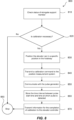
- Figure 7 illustrates a method 700 of measuring a position of an elevator car 220 within a hoistway 240 of an elevator system including an elongate tension member 226 operably connected to the elevator car 220 and configured to move the elevator car 220 within the hoistway 240.
- the method includes transmitting a pulse 334 from a first location on an elongate tension member 226 towards a detector at a second location on the elongate tension member 226.
- the first location and the second location may be any suitable location in the hoistway 240, so long as they are positioned such that a length of the elongate tension member 226 between the first location and the second location changes dependent on a position of the elevator car 220 in the hoistway 240.
- the first location may be on the elevator car 220, and the second location may be at an end terminal 208 of the elongate tension member 226 closest to the elevator car 220.
- the first location may be at a fixed position in the hoistway 240, for example at the traction sheave 204, and the second location may be on the elevator car 220.
- a first method step 710 may include recording a pulse start time.
- the pulse start time may be the time at which an initial pulse generator 328 sends the initial pulse 332 towards the pulse generator 202 at the first location.
- the pulse start time may be the time at which the pulse generator 202 at the first location transmits the pulse 334 along the elongate tension member 226 towards the detector unit 218 at the second location.
- a second method step 720 includes recording a time at which the pulse is received at the second location. This may include recording the time at which the pulse 334 is received by the detector unit 218 at the second location.
- the method 700 includes calculating, based on the recorded time, the length of the elongate tension member 226 along which the pulse is transmitted.
- the length of the elongate tension member 226 along which the pulse is transmitted may correspond to the length of elongate tension member between the first and second location.
- the method may include calculating a time interval between a pulse start time and the time at which the pulse 334 is received by the detector unit 218 at the second location. It will be appreciated that the time interval increases as the length of the elongate tension member 226 along which the pulse is transmitted increases.
- a time delay is present between the time at which the initial pulse 332 arrives at the pulse generator 202 and the time at which the pulse generator 202 sends the pulse 334 back to the detector 346.
- a time value equal to the time interval minus the time delay is proportional to the length of the elongate tension member 226 along which the pulse is transmitted.
- the method 700 includes determining, based on the calculated length, a position of the elevator car 220 in the hoistway 240 of the elevator system. This step may include referring to calibration information to determine the absolute position of the elevator car 220 in the hoistway 240.
- the calibration information may include an algorithm or look-up table to convert the calculated length to position information indicating the position of the elevator car 220 in the hoistway 240.
- the position information may be communicated to an elevator control unit 604.
- Figure 8 illustrates an example calibration process 800 for calibrating the position measurement system of the present disclosure.
- the calibration process 800 may be initially carried out at installation.
- the calibration process 800 may be repeated throughout the lifetime of the elevator system 200, 400 in response to changes in the properties of the elongate tension member 226 due to natural wear, for example.
- the status of the elongate tension member 226 is checked.
- the status may be checked using a wear detection device 602.
- the wear status of the elongate tension member 226 may be communicated to and read by the elevator control unit 604.
- the elevator control unit 604 may determine whether calibration of the position measurement system is necessary. For example, if the elevator control unit 604 determines that the wear status of the elongate tension member has changed by at least a predetermined amount since the last calibration, the elevator control unit 604 will determine that calibration is necessary.
- the calibration process 800 includes positioning the elevator car 220 in a specific position in the hoistway 240.
- the elevator car 220 may be positioned in the region of a door zone 222a-c, with the absolute position being measured by a secondary position reference system including position measurement tape 224a-c as described above with reference to figure 2 .
- the elevator control unit 604 may transmit a calibration command to the position measurement system control unit 336.
- the position measurement control unit 336 may communicate with the pulse generator 202 to send a pulse to the detector unit 218.
- the position measurement control unit may record the pulse start time and the time at which the pulse 334 is received by the detector unit 218.
- the position measurement control unit 336 may store the time interval between the pulse start time and the time at which the pulse is received by the detector unit as reference for the subsequent position measurements.
- Steps 830 to 860 may be repeated as necessary to store multiple reference points.
- the position measurement control unit 336 may determine an algorithm or generate a lookup table based on the reference points to convert time interval information to elevator car position information.
- the position measurement control unit 336 may transmit information indicating completion of calibration process to the elevator controller 604.
- the position measurement system is described above in the context of an elevator system with a 2:1 roping or 1:1 roping configuration, it will be appreciated that the position measurement system may also be employed in an elevator system with a different roping configuration by appropriately positioning the pulse generator and the detector unit such that the length of the elongate tension member in between changes according to the position of the elevator car in the hoistway.
- the initial pulse generator described in the examples above may be omitted and the pulse generator may transmit the pulse directly to the detector unit without the need for the initial pulse.
- a voltage may be applied directly to the pulse generator to generate and transmit a pulse along the elongate tension member towards the detector unit.
- the pulse start time would be recorded as the time at which the pulse generator sends the pulse towards the detector unit.
- the pulse generator and the detector unit are shown in specific positions in the examples described above, in other examples the pulse generator and the detector unit may be provided at different positions. These different positions may be any position in which one of the pulse generator and the detector moves dependent on the position of the elevator car within the hoistway such that the length of the elongate tension member along which the pulse is transmitted from the pulse generator to the detector unit changes dependent on the position of the elevator car within the hoistway.
- one of the pulse generator and detector unit may be located on either the elevator car or the counterweight, or at a location on the elongate tension member near the elevator car or the counterweight such that they move dependent on movement of the elevator car.
- the other of the pulse generator and the detector unit may be located at a fixed position within the hoistway such that the length of elongate tension member between the pulse generator and the detector unit changes dependent on the position of the elevator car within the hoistway.
- the elongate tension member 226 described herein may aptly be an elongate suspension member configured for suspending the elevator car within the hoistway.
- the suspension member is configured for supporting the weight of the elevator car and counterweight within the hoistway.
- the elongate tension member may be any suitable suspension member including a suspension belt, rope, or cable.
- the elongate tension member 226 in any of the examples described herein may include at least one electrically conductive component.
- the pulse generator 202 may be configured to transmit the pulse, which may be an electrical pulse, along the electrically conductive component.
- the initial pulse generator 328 may be configured to transmit the initial pulse, which may be an electrical pulse, along the electrically conductive component.
- the electrically conductive component may aptly be the tension cords 338a, 338b in the examples described above. That is the tension cords 338a, 338b are aptly electrically conductive.
- the elongate tension member 226 may include an electrically conductive component provided specifically for transmitting the pulse along the elongate tension member 226.
- an electrically conductive wire may be embedded within a belt or rope forming the elongate tension member 226.
Landscapes
- Engineering & Computer Science (AREA)
- Automation & Control Theory (AREA)
- Computer Networks & Wireless Communication (AREA)
- Physics & Mathematics (AREA)
- General Physics & Mathematics (AREA)
- Indicating And Signalling Devices For Elevators (AREA)
- Maintenance And Inspection Apparatuses For Elevators (AREA)
Description
- This disclosure relates to an elevator position measurement system, which determines the position of an elevator car within an elevator hoistway and a method of measuring a position of an elevator car within a hoistway of an elevator system.
- It is known to provide an elevator hoistway with a length of tape, arranged to extend vertically in the hoistway, and fixedly fastened to the hoistway wall. The elevator car includes a sensor e.g. a camera, able to sense certain features e.g. incremental markings, along the length of the tape, and the sensed features are used to determine the position of the elevator car within the hoistway. This prior art arrangement is described in greater detail below with reference to
Figure 1 . -
US 2006/243537 A1 discloses a position reference system for use with a conveyance, such as an elevator. The system includes a code affixed to or embedded within a suspension device or primary motion coupling such as a rope or coated steel belt. A reader in a fixed location determines the position of the conveyance. -
EP 3 587 329 A1 - Certain drawbacks with such known position measurement tape arrangements have been appreciated and the elevator position measurement system according to the present disclosure seeks to address these shortcomings.
- According to a first aspect of the invention there is provided an elevator system according to claim 9.
- Optionally, the detector unit is positioned at a first end of the elongate tension member.
- Optionally, the pulse generator is configured to transmit the pulse along the elongate tension member in a direction towards the detector unit.
- Optionally, the pulse generator is mounted on the elevator car and the detector unit is mounted at a fixed position relative to the elongate tension member.
- Optionally, the pulse generator is mounted in a fixed position in the hoistway and the detector unit is mounted on the elevator car.
- Optionally, the elevator car position measurement system further comprises an initial pulse generator configured to send an initial pulse along the elongate tension member towards the pulse generator to thereby induce a current in the pulse generator.
- Optionally, the pulse generator is configured to transmit the pulse along the elongate tension member in a direction towards the detector unit in response to the induced current.
- Optionally, the elevator car position measurement system further comprises a terminating connector coupled to the elongate tension member and configured to prevent reflection of the initial pulse back towards the initial pulse generator.
- Optionally, the detector unit is configured to record a pulse start time, wherein the pulse start time is a time at which the pulse generator transmits the pulse along the elongate tension member or a time at which the initial pulse generator sends the initial pulse towards the pulse generator.
- Optionally, the detector unit further comprises a measurement system control unit configured to determine a time interval between the pulse start time and the time at which the pulse is received by the detector unit.
- Optionally, the measurement system control unit is configured to calculate, from the determined time interval, position information indicating the position of the elevator car within the hoistway.
- Optionally, the elevator system further comprises an elevator control unit, wherein the measurement system control unit is configured to transmit the position information to the elevator control unit.
- Optionally, the elongate tension member comprises a plurality of tension cords surrounded by a sheath, and the pulse generator is configured to send the pulse along one of the plurality of tension cords.
- According to a second aspect of the invention there is provided an elevator car position measurement system for an elevator system according to
claim 1. - According to a third aspect of invention there is provided a method of measuring a position of an elevator car within a hoistway of an elevator system comprising an elongate tension member operably connected to the elevator car and configured to move the elevator car within the hoistway, the method comprising:
- transmitting a pulse from a first location on an elongate tension member towards a second location on the elongate tension member, wherein a length of the elongate tension member between the first location and the second location changes dependent on a position of the elevator car within the hoistway;
- recording a time at which the pulse is received at the second location;
- calculating, based on the recorded time, the length of the elongate tension member along which the pulse is transmitted; and
- determining, based on the calculated length, a position of the elevator car within the hoistway of the elevator system.
- It will be appreciated that any of the optional features described above in relation to the first aspect of the disclosure may equally be combined with the second or third aspects of the disclosure.
- In various examples, the elongate tension member comprises a plurality of cords surrounded by a sheath. At least one of the cords, or a pair of the cords, is electrically conductive and configured to transmit the pulse from the pulse generator along the elongate tension member. This electrically conductive cord, or pair of cords, may comprise a metallic material (such as steel) and/or carbon. One or more of the cords are load-bearing cords. In some examples, the plurality of cords comprises load-bearing cords that are electrically conductive. This means that any of the load-bearing cords can be used to transmit an electrical pulse along the elongate tension member. In some other examples, the plurality of cords comprises load-bearing cords that are not electrically conductive (such as polymeric cords) and at least one electrically conductive component that is configured to transmit an electrical pulse along the elongate tension member in parallel with the load-bearing cords. This means there is an electrically conductive component that is dedicated to pulse transmission, which can be independent of the tension member's load-bearing capability.
- In some examples, the elongate tension member comprises a plurality of steels cords surrounded by a polymeric sheath, e.g. a coated steel belt.
- The examples described herein advantageously provide an elevator car position measurement system that does not require installation of position measurement tape along the complete height of the hoistway, and that utilises the elongate tension member already present in the system. This can reduce material cost and installation time as well as providing space gain in the hoistway due to missing position measurement tape.
- Furthermore, measurement of the position of the elevator car using the examples described herein is independent from temperature or expansion or contraction in the building structure, so can offer improved reliability compared to known systems.
- Some examples of this disclosure will now be described, by way of example only, with reference to the accompanying drawings, in which:
-
Figure 1 shows a perspective view of an elevator system including a position measurement tape, as is known in the art; -
Figure 2 illustrates an example of an elevator system according to the present disclosure configured with a 2:1 roping system; -
Figures 3a and3b illustrate a schematic of the elevator position measurement system shown inFigure 2 ; -
Figure 4 illustrates an example of an elevator system according to the present disclosure configured with a 1:1 roping system; -
Figures 5a and5b illustrate a schematic of the elevator position measurement system shown inFigure 2 ; -
Figure 6 illustrates communication between components of the elevator system; -
Figure 7 illustrates a method of measuring a position of an elevator car within a hoistway; and -
Figure 8 illustrates an example calibration process for the position measurement system. -
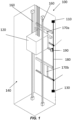
Figure 1 shows a perspective view of anelevator system 100 as is known in the art. Anelevator car 120 is arranged to move vertically within thehoistway 140, guided alongguide rails 160. Thehoistway 140 includes aposition measurement tape 180. Theposition measurement tape 180 is fixed to a hoistway wall by anupper fixing device 110, connected to the upper end of theposition measurement tape 180, and alower fixing device 130, connected to the lower end of theposition measurement tape 180. - The
elevator car 120 moves vertically within thehoistway 140, along theguide rails 160, driven by any suitable drive system as is known in the art, and controlled by an elevator system controller (not shown). Asensor 190 is mounted to theelevator car 120, in a position which is aligned with theposition measurement tape 180. - The
sensor 190 senses position markings e.g. increments, on theposition measurement tape 180 e.g. using a camera. Thesensor 190 can either process the collected data itself or pass the data to another component of the elevator system e.g. the elevator system controller, for further processing. This data is processed to determine a position i.e. height, within thehoistway 140. For example, each position marking could be unique and could be looked up in a lookup table (created in an initial calibration process) which includes the corresponding height for each position marking. In this way theposition measurement tape 180 is usable by theelevator system 100 to determine the vertical position of theelevator car 120 for any given position within thehoistway 140. - However, such a position reference system requires the
position measurement tape 180 to extend along the complete height of the hoistway 140 in order to determine the vertical position of theelevator car 120 at any given height. This can bring additional cost for the tape material, additional installation costs, and requires space in the hoistway. - An elevator system according to the present disclosure, as described herein below with reference to
Figures 2-8 , seeks to address these shortcomings of the priorart elevator system 100. -
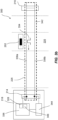
Figure 2 shows a side view of anelevator system 200 according to a first example of the present disclosure. Theelevator system 200 includes anelevator car 220 and anelongate tension member 226 operably coupled to theelevator car 220 and configured to move theelevator car 220 within ahoistway 240. - In this example, the
elevator car 220 is suspended by theelongate tension member 226 in a 2:1 roping configuration as is known in the art. In this configuration, theelongate tension member 226 is configured to move through atraction sheave 204 powered by anelevator drive unit 206 such that theelevator car 220 moves up and down within thehoistway 240. Acounterweight 250 is suspended from theelongate tension member 226 on an opposite side of thetraction sheave 204 to theelevator car 220. Both theelevator car 220 and thecounterweight 250 are suspended by theelongate tension member 226 via at least one pulley. Theelongate tension member 226 is fixed at each end with respect to the hoistway with anend terminal 208 at theelevator car 220 side of theelongate tension member 226 and afurther end terminal 212 at thecounterweight 250 side of theelongate tension member 226. - The
elongate tension member 226 may be any belt, cable or rope suitable for passing through thetraction sheave 204 and for supporting the weight of theelevator car 220 and thecounterweight 250. In this example, theelongate tension member 226 is a coated steel belt. - Referring also to
figures 3a and3b , theelevator system 200 includes aposition measurement system 300 including apulse generator 202. Thepulse generator 202 is configured to transmit apulse 334 along theelongate tension member 226. In other words, thepulse generator 202 is configured to send apulse 334 along at least one component of theelongate tension member 226. - Aptly, the
pulse generator 202 is configured to transmit anelectrical pulse 334 along theelongate tension member 226, and in particular along an electrically conductive component of theelongate tension member 226. For example, thepulse generator 334 is configured to induce anelectrical pulse 334 along theelongate tension member 226 by electromagnetic induction. - The
position measurement system 300 further includes adetector unit 218. Thedetector unit 218 is configured to receive thepulse 334 from thepulse generator 202 and record a time at which thepulse 334 is received. Thedetector unit 218 includes amonitoring connection 214 configured to electrically couple thedetector unit 218 to theelongate tension member 226. - The
pulse generator 202 and thedetector unit 218 are arranged such that a length of theelongate tension member 226 along which thepulse 334 is transmitted changes dependent on a position of theelevator car 220 in thehoistway 240. - In this example, the
pulse generator 202 is mounted on theelevator car 220 and thedetector unit 218 is mounted at a fixed position relative to theelongate tension member 226. In this example thedetector unit 218 is mounted at theend terminal 208 of theelongate tension member 226 closest to theelevator car 220. As such, as theelevator car 220 moves vertically up and down within thehoistway 240, the length of the portion ofelongate tension member 226 between thepulse generator 202 and thedetector unit 218 changes according to the position of theelevator car 220. The length of theelongate tension member 226 through which thepulse 334 travels from thepulse generator 202 to thedetector unit 218 therefore changes according to the position of theelevator car 220 within thehoistway 240. - The
position measurement system 300 is configured to determine the length of theelongate tension member 226 along which thepulse 334 is transmitted based on the time thedetector unit 218 receives thepulse 334. The position of theelevator car 220 can then be determined according to the determined length ofelongate tension member 226 along which thepulse 334 is transmitted between thepulse generator 202 and thedetector unit 218. -
Figures 3a and3b illustrate the operation of theposition measurement system 300 offigure 2 in further detail. Theposition measurement system 300 further includes aninitial pulse generator 328, which in this example is located at thedetector unit 218. In this example, theposition measurement system 300 includes a positionmeasurement control unit 336, which includes theinitial pulse generator 328. - The
initial pulse generator 328 is configured to send aninitial pulse 332 along theelongate tension member 226 towards thepulse generator 202, which in this example is positioned on theelevator car 220. Theinitial pulse 332 induces a current in thepulse generator 202. In response to the induced current, thepulse generator 202 is configured to transmit apulse 334 back towards thedetector unit 218 as shown infigure 3b . In some examples, there may be a time delay between theinitial pulse 332 inducing the current in thepulse generator 202 and thepulse generator 202 transmitting thepulse 334 back to thedetector unit 218. In this example thepulse generator 202 is an inductive pulse transceiver. - The
detector unit 218 may include apulse detector 346 configured to detect thepulse 334 and a measurementsystem control unit 336 configured to record the time at which thepulse 334 is received. - In addition to recording the time at which the
pulse 334 is received by thedetector unit 218, thedetector unit 218 is further configured to record a pulse start time. A time interval between the pulse start time and the time at which thepulse 334 is received by thedetector unit 218 may then be used to calculate the length ofelongate tension member 226 along which thepulse 334 has travelled, i.e. the length ofelongate tension member 226 between thepulse generator 202 and thedetector unit 218. - In this example the pulse start time is the time at which the
initial pulse generator 328 sends theinitial pulse 332 towards thepulse generator 202. In other examples, the pulse start time may be the time at which thepulse generator 202 transmits thepulse 334 along the elongate tension member towards thedetector unit 218. - The measurement
system control unit 336 is further configured to determine a time interval between the pulse start time and the time at which thepulse 334 is received by thedetector unit 218. - In this example the
detector unit 218 includes the measurementsystem control unit 336. In some examples, the measurementsystem control unit 336 may include a time-to-digital converter 336a configured to record the pulse start time and the time at which thepulse 334 is received by thepulse detector 346. The time-to-digital converter 336a is discussed in more detail below with reference tofigure 6 . The time-to-digital converter 336a may include theinitial pulse generator 328 and thepulse detector 346. In this way, the pulse detection and the pulse generation may be an integral function of the time-to-digital converter 336a such that pulse generation and pulse detection may both be performed by the time-to-digital converter 336a. - The measurement
system control unit 336 is further configured to calculate, from the determined time interval, position information indicating the position of theelevator car 220 within thehoistway 240. To calculate the position information, the measurementsystem control unit 336 may first determine the length of theelongate tension member 226 along which thepulse 334 is transmitted based on the determined time interval. The determined length of theelongate tension member 226 along which thepulse 334 is transmitted may then be used to determine the position of theelevator car 220, for example using a predetermined algorithm or a look up table. The predetermined algorithm or look-up table may be determined using a calibration process as described in more detail below with reference tofigure 7 . - As described above, in this example the
elongate tension member 226 is a coated steel belt. The coated steel belt includes at least one pair oftension cords elongate tension member 226 may further include a plurality of tension cords configured for load-bearing. Thetension cords tension cords tension cords sheath 342. - As shown in
figures 3a and3b , themonitoring connection 214 is configured to couple to each of thetension cords first tension cord 338a is coupled to theinitial pulse generator 328 and the measurementsystem control unit 336 including thepulse detector 346. Thesecond tension cord 338b is coupled to a terminatingconnector 344. Thetension cords shortening connection 216 at or near theend terminal 212 adjacent thecounterweight 250. Theinitial pulse generator 328 and thepulse generator 202 are configured to send theinitial pulse 332 and thepulse 334 along afirst tension cord 338a of the pair oftension cords - To help prevent reflection of the
initial pulse 332 back towards theinitial pulse generator 328, the terminatingconnector 344 is coupled to thesecond tension cord 338b and is configured to have an impedance substantially equal to the characteristic impedance of theelongate tension member 226. - The
initial pulse generator 328 and thepulse generator 202 may be configured to generate any pulse that is suitable for travelling along thetension cords initial pulse generator 328 and thepulse generator 202 are configured to generate a voltage pulse with a square waveform, but it will be appreciated that other waveforms would also be suitable, for example a sinusoidal, triangular or saw tooth waveform may also be suitable. - Referring back to
figure 2 , theelevator system 200 may further include a secondary elevator car position reference system. The secondary elevator car position reference system includesposition measurement tape 224a-c located at eachdoor zone 222a-c in thehoistway 240. Asensor 228 is mounted to theelevator car 220, in a position which aligns with theposition measurement tape 224a-c. Thesensor 228 senses position markings e.g. increments, on theposition measurement tape 224a-c, e.g. using a camera. - The
sensor 228 can either process the collected data itself or pass the data to another component of the elevator system e.g. an elevator system control unit, for further processing. - The secondary elevator car position reference system can be utilized in combination with the
position measurement system 300 to provide high resolution position measurements of theelevator car 220 at eachdoor zone 222a-c within the hoistway. Theposition measurement system 300 of the present disclosure enables position measurement of the elevator car through the full height of thehoistway 240 without the need for the higher resolutionposition measurement tape 224a-c to be positioned along the full height of thehoistway 240. Thus, shorter lengths ofposition measurement tape 224a-c may be utilised, thereby reducing material and installation costs. Furthermore, the space required in thehoistway 240 is reduced since theposition measurement tape 224a-c is only provided at thedoor zones 222a-c. -
Figure 4 shows a side view of anelevator system 400 according to a second example of the present disclosure. Theelevator system 400 includes anelevator car 220 and anelongate tension member 226 operably coupled to theelevator car 220 and configured to move theelevator car 220 within ahoistway 240. - In this example, the
elevator car 220 is suspended from a first end of theelongate tension member 226 in a 1:1 roping configuration as is known in the art. In this configuration, theelongate tension member 226 is configured to move through atraction sheave 204 powered by anelevator drive unit 206 such that theelevator car 220 moves up and down within thehoistway 240. Acounterweight 250 is suspended from a second end of theelongate tension member 226 and on an opposite side of thetraction sheave 204 to theelevator car 220. - The
elevator system 400 includes many of the same components as theelevator system 200 described above in relation tofigures 2 and3 , which will not be described again in detail. - However, in this example the
pulse generator 202 is mounted at a fixed position in thehoistway 240 rather than at theelevator car 220. In this example, thepulse generator 202 is mounted at thetraction sheave 204. Thedetector unit 218 is mounted on theelevator car 220 such that it is in a fixed position relative to theend terminal 208 of theelongate tension member 226. In this example, thedetector unit 218 is positioned at the first end of theelongate tension member 226, which in this case is at theelevator car 220. In this way, as theelevator car 220 moves vertically up and down within thehoistway 240, the length of the portion ofelongate tension member 226 between thepulse generator 202 and thedetector unit 218 changes according to the position of theelevator car 220. The length of theelongate tension member 226 through which the pulse travels from thepulse generator 202 to thedetector unit 218 therefore changes according to the position of theelevator car 220 within thehoistway 240. -
Figures 5a and5b illustrate the operation of theposition measurement system 500 offigure 4 in further detail. It will be appreciated that the operation of the system offigures 5a and5b is substantially identical to that described with reference tofigures 3a and3b , except for the positioning of thedetector unit 218 and thepulse generator 202 within theelevator system 400 as described above with reference tofigure 4 . -
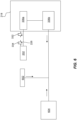
Figure 6 illustrates communication between components of the position measurement system and the elevator system. The position measurement system is substantially the same as in the examples described above, and includes apulse generator 202 and adetector unit 218 including a measurementsystem control unit 336. In this example, the measurementsystem control unit 336 includes a time-to-digital converter 336a and amicrocontroller 336b. - The elevator system further includes a
wear detection device 602. Thewear detection device 602 may be configured to monitor the physical condition of theelongate tension member 226. For example, thewear detection device 602 may be configured to monitor the condition of theelongate tension member 226 by monitoring the electrical resistance of one ormore tension cords elongate tension member 226. - The elevator system further includes an
elevator control unit 604. Theelevator control unit 604 is configured to communicate with thedetector unit 218 and thewear detection device 602. For example, theelevator control unit 604 may be configured to transmit position measurement and/or a calibration command and parameters to thedetector unit 218. Theelevator control unit 604 may also be configured to read position information from thedetector unit 218. Theelevator control unit 604 may be further configured to communicate with thewear detection device 602 and read wear status of theelongate tension member 226 from thewear detection device 602. - The
pulse generator 202 may be an inductive pulse transceiver and operates as described above in relation tofigures 2 to 5 . Thepulse generator 202 is configured to receive apulse 332 from thedetector unit 218 and, in response, send apulse 334 to thedetector unit 218 along theelongate tension member 226. - In this example, the measurement
system control unit 336 includes the time-to-digital converter 336a and themicrocontroller 336b. The time-to-digital converter 336a is configured to send thepulse 332 pulse to thepulse generator 202. For example, the time-to-digital converter 336a may include an initial pulse generator configured to send thepulse 332 to thepulse generator 202. The time-to-digital converter 336a is also configured to receive thepulse 334 from thepulse generator 202. For example, the time-to-digital converter 336a may include a pulse detector to detect thepulse 334 from thepulse generator 202. The time-to-digital converter 336a may further be configured to record a first timestamp relating to the time at which the time-to-digital converter 336a sends theinitial pulse 332 to thepulse generator 202 and a second timestamp relating to the time at which the time-to-digital converter 336a receives thepulse 334 from thepulse generator 202. The first and second timestamps may be stored in a memory in the time-to-digital converter 336a. - The
microcontroller 336b may be configured to manage the time-to-digital converter 336a. This may include reading the first and second timestamps from the time-to-digital converter 336a and converting the timestamps into position information relating to the position of theelevator car 220 in thehoistway 240. Themicrocontroller 336b may be configured to transmit the position information to theelevator control unit 604. The microcontroller may be further configured to store calibration reference information, as will be described further below with reference tofigure 8 . - In this example the
wear detection device 602 is provided separately to thedetector unit 218. However, it will be appreciated that in some examples thewear detection device 602 may be provided integrally together with thedetector unit 218. In this configuration both thewear detection device 602 and the position measurement system may advantageously couple to the pair oftension cords elongate tension member 226 at the same location. As such, it is possible that the position measurement system of the present disclosure may be retrofitted to an existing elevator system, which includes awear detection device 602. - For example, when retrofitting to an existing installation, the
detector unit 218 may be provided separately to thewear detection device 602. In this case, thedetector unit 218 and thewear detection device 602 may each couple to theelongate tension member 226 via thesame monitoring connection 214. - The
wear detection device 602 typically includes a microprocessor communicating with theelevator control unit 604. As such, the position measurement system may optionally share the same microprocessor and communication components with thewear detection device 602. In other words, thedetector unit 218 may be integrated with thewear detection device 602 and both thedetector unit 218 and the wear detection device may couple to theelongate tension member 226 via thesame monitoring connection 214. This configuration may be advantageous for new installations to help reduce component parts, and reduce installation time and cost. -
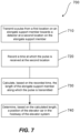
Figure 7 illustrates amethod 700 of measuring a position of anelevator car 220 within ahoistway 240 of an elevator system including anelongate tension member 226 operably connected to theelevator car 220 and configured to move theelevator car 220 within thehoistway 240. - At a
first step 710 the method includes transmitting apulse 334 from a first location on anelongate tension member 226 towards a detector at a second location on theelongate tension member 226. The first location and the second location may be any suitable location in thehoistway 240, so long as they are positioned such that a length of theelongate tension member 226 between the first location and the second location changes dependent on a position of theelevator car 220 in thehoistway 240. - For example, as described above in an elevator system configured with a 2:1 roping configuration, the first location may be on the
elevator car 220, and the second location may be at anend terminal 208 of theelongate tension member 226 closest to theelevator car 220. In an elevator system configured with a 1:1 roping configuration, the first location may be at a fixed position in thehoistway 240, for example at thetraction sheave 204, and the second location may be on theelevator car 220. - A
first method step 710 may include recording a pulse start time. As described above, the pulse start time may be the time at which aninitial pulse generator 328 sends theinitial pulse 332 towards thepulse generator 202 at the first location. In other examples, the pulse start time may be the time at which thepulse generator 202 at the first location transmits thepulse 334 along theelongate tension member 226 towards thedetector unit 218 at the second location. - A
second method step 720 includes recording a time at which the pulse is received at the second location. This may include recording the time at which thepulse 334 is received by thedetector unit 218 at the second location. - At
step 730 themethod 700 includes calculating, based on the recorded time, the length of theelongate tension member 226 along which the pulse is transmitted. The length of theelongate tension member 226 along which the pulse is transmitted may correspond to the length of elongate tension member between the first and second location. To calculate the length of tension member between the first and second location the method may include calculating a time interval between a pulse start time and the time at which thepulse 334 is received by thedetector unit 218 at the second location. It will be appreciated that the time interval increases as the length of theelongate tension member 226 along which the pulse is transmitted increases. In practice, a time delay is present between the time at which theinitial pulse 332 arrives at thepulse generator 202 and the time at which thepulse generator 202 sends thepulse 334 back to thedetector 346. As such, a time value equal to the time interval minus the time delay is proportional to the length of theelongate tension member 226 along which the pulse is transmitted. - At
step 740 themethod 700 includes determining, based on the calculated length, a position of theelevator car 220 in thehoistway 240 of the elevator system. This step may include referring to calibration information to determine the absolute position of theelevator car 220 in thehoistway 240. For example, the calibration information may include an algorithm or look-up table to convert the calculated length to position information indicating the position of theelevator car 220 in thehoistway 240. As described above, the position information may be communicated to anelevator control unit 604. -
Figure 8 illustrates anexample calibration process 800 for calibrating the position measurement system of the present disclosure. Thecalibration process 800 may be initially carried out at installation. In addition, thecalibration process 800 may be repeated throughout the lifetime of theelevator system elongate tension member 226 due to natural wear, for example. - At
step 810 the status of theelongate tension member 226 is checked. The status may be checked using awear detection device 602. The wear status of theelongate tension member 226 may be communicated to and read by theelevator control unit 604. - At
step 820 theelevator control unit 604 may determine whether calibration of the position measurement system is necessary. For example, if theelevator control unit 604 determines that the wear status of the elongate tension member has changed by at least a predetermined amount since the last calibration, theelevator control unit 604 will determine that calibration is necessary. - At
step 830 thecalibration process 800 includes positioning theelevator car 220 in a specific position in thehoistway 240. For example, theelevator car 220 may be positioned in the region of adoor zone 222a-c, with the absolute position being measured by a secondary position reference system includingposition measurement tape 224a-c as described above with reference tofigure 2 . - At
step 840 theelevator control unit 604 may transmit a calibration command to the position measurementsystem control unit 336. - At
step 850 the positionmeasurement control unit 336 may communicate with thepulse generator 202 to send a pulse to thedetector unit 218. The position measurement control unit may record the pulse start time and the time at which thepulse 334 is received by thedetector unit 218. - At
step 860 the positionmeasurement control unit 336 may store the time interval between the pulse start time and the time at which the pulse is received by the detector unit as reference for the subsequent position measurements. -
Steps 830 to 860 may be repeated as necessary to store multiple reference points. The positionmeasurement control unit 336 may determine an algorithm or generate a lookup table based on the reference points to convert time interval information to elevator car position information. - At
step 870 the positionmeasurement control unit 336 may transmit information indicating completion of calibration process to theelevator controller 604. - It will be appreciated that various modifications may be made to the examples described herein. For example, although the position measurement system is described above in the context of an elevator system with a 2:1 roping or 1:1 roping configuration, it will be appreciated that the position measurement system may also be employed in an elevator system with a different roping configuration by appropriately positioning the pulse generator and the detector unit such that the length of the elongate tension member in between changes according to the position of the elevator car in the hoistway.
- It will also be appreciated that in some examples the initial pulse generator described in the examples above may be omitted and the pulse generator may transmit the pulse directly to the detector unit without the need for the initial pulse. For example, a voltage may be applied directly to the pulse generator to generate and transmit a pulse along the elongate tension member towards the detector unit. In this instance, the pulse start time would be recorded as the time at which the pulse generator sends the pulse towards the detector unit.
- Although the pulse generator and the detector unit are shown in specific positions in the examples described above, in other examples the pulse generator and the detector unit may be provided at different positions. These different positions may be any position in which one of the pulse generator and the detector moves dependent on the position of the elevator car within the hoistway such that the length of the elongate tension member along which the pulse is transmitted from the pulse generator to the detector unit changes dependent on the position of the elevator car within the hoistway.
- For example, one of the pulse generator and detector unit may be located on either the elevator car or the counterweight, or at a location on the elongate tension member near the elevator car or the counterweight such that they move dependent on movement of the elevator car. The other of the pulse generator and the detector unit may be located at a fixed position within the hoistway such that the length of elongate tension member between the pulse generator and the detector unit changes dependent on the position of the elevator car within the hoistway.
- The
elongate tension member 226 described herein may aptly be an elongate suspension member configured for suspending the elevator car within the hoistway. The suspension member is configured for supporting the weight of the elevator car and counterweight within the hoistway. For example, the elongate tension member may be any suitable suspension member including a suspension belt, rope, or cable. - The
elongate tension member 226 in any of the examples described herein may include at least one electrically conductive component. Thepulse generator 202 may be configured to transmit the pulse, which may be an electrical pulse, along the electrically conductive component. Similarly, theinitial pulse generator 328 may be configured to transmit the initial pulse, which may be an electrical pulse, along the electrically conductive component. - The electrically conductive component may aptly be the
tension cords tension cords - In other examples the
elongate tension member 226 may include an electrically conductive component provided specifically for transmitting the pulse along theelongate tension member 226. For example, an electrically conductive wire may be embedded within a belt or rope forming theelongate tension member 226. - It will be appreciated by those skilled in the art that the disclosure has been illustrated by describing one or more examples thereof, but is not limited to these examples; many variations and modifications are possible, within the scope of the accompanying claims.
Claims (15)
- An elevator car position measurement system (300, 500) for an elevator system (200, 400) comprising an elongate tension member (226) operably connected to an elevator car (220) and configured to move the elevator car (220) within the hoistway (240), the elevator car position measurement system (300, 500) comprising:a pulse generator (202) configured for transmitting a pulse (334) along the elongate tension member (226);a detector unit (218) configured to receive the pulse (334) from the pulse generator (202) after the pulse (334) has been transmitted along a length of the elongate tension member (226) and to record a time at which the pulse (334) is received;wherein one of the pulse generator (202) and the detector unit (218) is configured to be arranged to move within the hoistway (240) dependent on a position of the elevator car (220) within the hoistway (240) such that, in use, a length of the elongate tension member (226) along which the pulse (334) is transmitted changes dependent on a position of the elevator car (220) within the hoistway (240), andwherein the elevator car position measurement system (300, 500) is configured to calculate the length of the elongate tension member (226) along which the pulse (334) is transmitted based on the recorded time, and determine the position of the elevator car (220) within the hoistway (240) based on the determined length.
- The elevator car position measurement system (300, 500) according to claim 1, wherein the pulse generator (202) is configured to transmit the pulse (334) along the elongate tension member (226) in a direction towards the detector unit (218).
- The elevator car position measurement system (300, 500) according to claim 1 or claim 2, further comprising an initial pulse generator (328) configured to send an initial pulse (332) along the elongate tension member (226) towards the pulse generator (202) to thereby induce a current in the pulse generator (202).
- The elevator car position measurement system (300, 500) according to claim 3, wherein the pulse generator (202) is configured to transmit the pulse (334) along the elongate tension member (226) in a direction towards the detector unit (218) in response to the induced current.
- The elevator car position measurement system (300, 500) according to claim 3 or claim 4, further comprising a terminating connector (334) coupled to the elongate tension member (226) and configured to prevent reflection of the initial pulse (332) back towards the initial pulse generator (328).
- The elevator car position measurement system (300, 500) according to any preceding claim, wherein the detector unit (218) is configured to record a pulse start time, wherein the pulse start time is a time at which the pulse generator (202) transmits the pulse (334) along the elongate tension member (226) or a time at which the initial pulse generator (328) sends the initial pulse (332) towards the pulse generator (202).
- The elevator car position measurement system (300, 500) according to claim 6, wherein the detector unit (218) further comprises a measurement system control unit (336) configured to determine a time interval between the pulse start time and the time at which the pulse (334) is received by the detector unit (218).
- The elevator car position measurement system (300, 500) according to claim 7, wherein the measurement system control unit (336) is configured to calculate, from the determined time interval, position information indicating the position of the elevator car (220) within the hoistway (240).
- An elevator system (200, 400) comprising an elevator car (220), an elongate tension member (226) operably connected to the elevator car (220) and configured to move the elevator car (220) within a hoistway (240), and an elevator car position measurement system (300, 500) according to any preceding claim.
- The elevator system (200, 400) according to claim 9, wherein the detector unit (218) is positioned at a first end (208) of the elongate tension member (226).
- The elevator system (200, 400) according to claim 9 or claim 10, wherein the pulse generator (202) is mounted on the elevator car (220) and the detector unit (218) is mounted at a fixed position relative to the elongate tension member (226).
- The elevator system (200, 400) according to any of claims 9 to 11, wherein the pulse generator (202) is mounted in a fixed position in the hoistway (240) and the detector unit (218) is mounted on the elevator car (220).
- The elevator system (200, 400) according to any of claims 9 to 12 when dependent on claim 8, further comprising an elevator control unit (604), wherein the measurement system control unit (336) is configured to transmit the position information to the elevator control unit (604).
- The elevator system (200, 400) according to any of claims 9 to 13, wherein the elongate tension member (226) comprises a plurality of tension cords (338a, 338b) surrounded by a sheath (342), and wherein the pulse generator (202) is configured to send the pulse (334) along one of the plurality of tension cords (338a, 338b).
- A method of measuring a position of an elevator car (220) within a hoistway (240) of an elevator system (200, 400) comprising an elongate tension member (226) operably connected to the elevator car (220) and configured to move the elevator car (220) within the hoistway (240), the method comprising:transmitting a pulse (334) from a first location on an elongate tension member (226) towards a second location on the elongate tension member (226), wherein a length of the elongate tension member (226) between the first location and the second location changes dependent on a position of the elevator car (220) within the hoistway (240);recording a time at which the pulse (334) is received at the second location;calculating, based on the recorded time, the length of the elongate tension member (226) along which the pulse (334) is transmitted; anddetermining, based on the calculated length, a position of the elevator car (220) within the hoistway (240) of the elevator system (200, 400).
Priority Applications (3)
| Application Number | Priority Date | Filing Date | Title |
|---|---|---|---|
| EP22159813.9A EP4238917B1 (en) | 2022-03-02 | 2022-03-02 | Elevator position measurement system |
| US17/974,827 US20230278827A1 (en) | 2022-03-02 | 2022-10-27 | Elevator position measurement system |
| CN202211456469.7A CN116692627B (en) | 2022-03-02 | 2022-11-21 | Elevator system, elevator position measurement system and method for measuring elevator car position |
Applications Claiming Priority (1)
| Application Number | Priority Date | Filing Date | Title |
|---|---|---|---|
| EP22159813.9A EP4238917B1 (en) | 2022-03-02 | 2022-03-02 | Elevator position measurement system |
Publications (2)
| Publication Number | Publication Date |
|---|---|
| EP4238917A1 EP4238917A1 (en) | 2023-09-06 |
| EP4238917B1 true EP4238917B1 (en) | 2025-06-25 |
Family
ID=80625471
Family Applications (1)
| Application Number | Title | Priority Date | Filing Date |
|---|---|---|---|
| EP22159813.9A Active EP4238917B1 (en) | 2022-03-02 | 2022-03-02 | Elevator position measurement system |
Country Status (3)
| Country | Link |
|---|---|
| US (1) | US20230278827A1 (en) |
| EP (1) | EP4238917B1 (en) |
| CN (1) | CN116692627B (en) |
Family Cites Families (9)
| Publication number | Priority date | Publication date | Assignee | Title |
|---|---|---|---|---|
| JPH05193852A (en) * | 1992-01-20 | 1993-08-03 | Toshiba Corp | Elevator car position detecting device |
| US5883345A (en) * | 1997-12-23 | 1999-03-16 | Otis Elevator Company | Sonic position measurement system |
| US7540357B2 (en) * | 2003-05-15 | 2009-06-02 | Otis Elevator Company | Position reference system for elevators |
| JP2006176215A (en) * | 2004-12-20 | 2006-07-06 | Toshiba Elevator Co Ltd | Elevator device |
| WO2017153250A1 (en) * | 2016-03-10 | 2017-09-14 | Inventio Ag | Supporting means for an elevator installation, with multiple sensors arranged along the supporting means |
| US11299370B2 (en) * | 2018-06-29 | 2022-04-12 | Otis Elevator Company | Data transmission via elevator system tension member |
| US12351434B2 (en) * | 2018-12-14 | 2025-07-08 | Otis Elevator Company | Safety system based on hoistway access detection |
| CN210914849U (en) * | 2019-09-27 | 2020-07-03 | 曼隆蒂森克虏伯电梯有限公司 | Elevator car position and running speed measuring device |
| US11932515B2 (en) * | 2021-04-05 | 2024-03-19 | Otis Elevator Company | Elevator tension member monitor |
-
2022
- 2022-03-02 EP EP22159813.9A patent/EP4238917B1/en active Active
- 2022-10-27 US US17/974,827 patent/US20230278827A1/en active Pending
- 2022-11-21 CN CN202211456469.7A patent/CN116692627B/en active Active
Also Published As
| Publication number | Publication date |
|---|---|
| US20230278827A1 (en) | 2023-09-07 |
| EP4238917A1 (en) | 2023-09-06 |
| CN116692627A (en) | 2023-09-05 |
| CN116692627B (en) | 2026-02-27 |
Similar Documents
| Publication | Publication Date | Title |
|---|---|---|
| US11535488B2 (en) | Elevator position detection systems | |
| EP2749521B1 (en) | A method in rope condition monitoring of an elevator rope | |
| EP4087806B1 (en) | Elevator safety system | |
| JPH11246139A (en) | Elevator car position determination method and apparatus | |
| JPH09110322A (en) | Elevator position measuring system, elevator system, and elevator car position measuring method | |
| EP3687930B1 (en) | A method and an elevator system for defining an elongation of an elevator car suspension means | |
| JP2008509868A (en) | Elevator car positioning system | |
| CN111942995A (en) | Elevator rope inspection system | |
| US11618649B2 (en) | Elevator apparatus | |
| CN109580728A (en) | Cable degradation | |
| EP4238917B1 (en) | Elevator position measurement system | |
| US12552639B2 (en) | Movement evaluation method for an elevator car | |
| US6809650B2 (en) | Method and device for determining the state of a rail stretch | |
| JP4317863B2 (en) | Elevator | |
| EP4003892B1 (en) | Method and arrangement for determining a current precise position of an elevator car in an elevator hoistway | |
| US20210214188A1 (en) | Elevator system with method of position detection of a car | |
| IT201800003748A1 (en) | A device for verifying the correct tensioning of the contact rope in an electric traction line | |
| CN111874779A (en) | Method and apparatus for detecting the position of an elevator car | |
| WO2013035368A1 (en) | Elevator stopping position-detecting device | |
| CN111196535B (en) | Elevator device and method for monitoring an elevator device by means of an elevator control system | |
| EP4566980A2 (en) | Elevator tension member elongation and stiffness monitoring system | |
| WO2012164703A1 (en) | Elevator device | |
| HK40065605A (en) | Movement evaluation method for an elevator car | |
| HK1136039B (en) | Tensile support strength monitoring system and method | |
| HK1136039A1 (en) | Tensile support strength monitoring system and method |
Legal Events
| Date | Code | Title | Description |
|---|---|---|---|
| PUAI | Public reference made under article 153(3) epc to a published international application that has entered the european phase |
Free format text: ORIGINAL CODE: 0009012 |
|
| STAA | Information on the status of an ep patent application or granted ep patent |
Free format text: STATUS: THE APPLICATION HAS BEEN PUBLISHED |
|
| AK | Designated contracting states |
Kind code of ref document: A1 Designated state(s): AL AT BE BG CH CY CZ DE DK EE ES FI FR GB GR HR HU IE IS IT LI LT LU LV MC MK MT NL NO PL PT RO RS SE SI SK SM TR |
|
| STAA | Information on the status of an ep patent application or granted ep patent |
Free format text: STATUS: REQUEST FOR EXAMINATION WAS MADE |
|
| 17P | Request for examination filed |
Effective date: 20240301 |
|
| RBV | Designated contracting states (corrected) |
Designated state(s): AL AT BE BG CH CY CZ DE DK EE ES FI FR GB GR HR HU IE IS IT LI LT LU LV MC MK MT NL NO PL PT RO RS SE SI SK SM TR |
|
| GRAP | Despatch of communication of intention to grant a patent |
Free format text: ORIGINAL CODE: EPIDOSNIGR1 |
|
| STAA | Information on the status of an ep patent application or granted ep patent |
Free format text: STATUS: GRANT OF PATENT IS INTENDED |
|
| INTG | Intention to grant announced |
Effective date: 20250122 |
|
| GRAS | Grant fee paid |
Free format text: ORIGINAL CODE: EPIDOSNIGR3 |
|
| GRAA | (expected) grant |
Free format text: ORIGINAL CODE: 0009210 |
|
| STAA | Information on the status of an ep patent application or granted ep patent |
Free format text: STATUS: THE PATENT HAS BEEN GRANTED |
|
| AK | Designated contracting states |
Kind code of ref document: B1 Designated state(s): AL AT BE BG CH CY CZ DE DK EE ES FI FR GB GR HR HU IE IS IT LI LT LU LV MC MK MT NL NO PL PT RO RS SE SI SK SM TR |
|
| REG | Reference to a national code |
Ref country code: GB Ref legal event code: FG4D |
|
| REG | Reference to a national code |
Ref country code: CH Ref legal event code: EP |
|
| REG | Reference to a national code |
Ref country code: CH Ref legal event code: EP |
|
| REG | Reference to a national code |
Ref country code: IE Ref legal event code: FG4D |
|
| REG | Reference to a national code |
Ref country code: DE Ref legal event code: R096 Ref document number: 602022016280 Country of ref document: DE |
|
| PG25 | Lapsed in a contracting state [announced via postgrant information from national office to epo] |
Ref country code: FI Free format text: LAPSE BECAUSE OF FAILURE TO SUBMIT A TRANSLATION OF THE DESCRIPTION OR TO PAY THE FEE WITHIN THE PRESCRIBED TIME-LIMIT Effective date: 20250625 |
|
| REG | Reference to a national code |
Ref country code: LT Ref legal event code: MG9D |
|
| PG25 | Lapsed in a contracting state [announced via postgrant information from national office to epo] |
Ref country code: NO Free format text: LAPSE BECAUSE OF FAILURE TO SUBMIT A TRANSLATION OF THE DESCRIPTION OR TO PAY THE FEE WITHIN THE PRESCRIBED TIME-LIMIT Effective date: 20250925 Ref country code: GR Free format text: LAPSE BECAUSE OF FAILURE TO SUBMIT A TRANSLATION OF THE DESCRIPTION OR TO PAY THE FEE WITHIN THE PRESCRIBED TIME-LIMIT Effective date: 20250926 |
|
| PG25 | Lapsed in a contracting state [announced via postgrant information from national office to epo] |
Ref country code: BG Free format text: LAPSE BECAUSE OF FAILURE TO SUBMIT A TRANSLATION OF THE DESCRIPTION OR TO PAY THE FEE WITHIN THE PRESCRIBED TIME-LIMIT Effective date: 20250625 |
|
| PG25 | Lapsed in a contracting state [announced via postgrant information from national office to epo] |
Ref country code: HR Free format text: LAPSE BECAUSE OF FAILURE TO SUBMIT A TRANSLATION OF THE DESCRIPTION OR TO PAY THE FEE WITHIN THE PRESCRIBED TIME-LIMIT Effective date: 20250625 |
|
| PG25 | Lapsed in a contracting state [announced via postgrant information from national office to epo] |
Ref country code: RS Free format text: LAPSE BECAUSE OF FAILURE TO SUBMIT A TRANSLATION OF THE DESCRIPTION OR TO PAY THE FEE WITHIN THE PRESCRIBED TIME-LIMIT Effective date: 20250925 |
|
| PG25 | Lapsed in a contracting state [announced via postgrant information from national office to epo] |
Ref country code: LV Free format text: LAPSE BECAUSE OF FAILURE TO SUBMIT A TRANSLATION OF THE DESCRIPTION OR TO PAY THE FEE WITHIN THE PRESCRIBED TIME-LIMIT Effective date: 20250625 |
|
| REG | Reference to a national code |
Ref country code: NL Ref legal event code: MP Effective date: 20250625 |
|
| PG25 | Lapsed in a contracting state [announced via postgrant information from national office to epo] |
Ref country code: NL Free format text: LAPSE BECAUSE OF FAILURE TO SUBMIT A TRANSLATION OF THE DESCRIPTION OR TO PAY THE FEE WITHIN THE PRESCRIBED TIME-LIMIT Effective date: 20250625 |
|
| PG25 | Lapsed in a contracting state [announced via postgrant information from national office to epo] |
Ref country code: PT Free format text: LAPSE BECAUSE OF FAILURE TO SUBMIT A TRANSLATION OF THE DESCRIPTION OR TO PAY THE FEE WITHIN THE PRESCRIBED TIME-LIMIT Effective date: 20251027 |
|
| REG | Reference to a national code |
Ref country code: AT Ref legal event code: MK05 Ref document number: 1806306 Country of ref document: AT Kind code of ref document: T Effective date: 20250625 |
|
| PG25 | Lapsed in a contracting state [announced via postgrant information from national office to epo] |
Ref country code: IS Free format text: LAPSE BECAUSE OF FAILURE TO SUBMIT A TRANSLATION OF THE DESCRIPTION OR TO PAY THE FEE WITHIN THE PRESCRIBED TIME-LIMIT Effective date: 20251025 |
|
| PG25 | Lapsed in a contracting state [announced via postgrant information from national office to epo] |
Ref country code: AT Free format text: LAPSE BECAUSE OF FAILURE TO SUBMIT A TRANSLATION OF THE DESCRIPTION OR TO PAY THE FEE WITHIN THE PRESCRIBED TIME-LIMIT Effective date: 20250625 Ref country code: SM Free format text: LAPSE BECAUSE OF FAILURE TO SUBMIT A TRANSLATION OF THE DESCRIPTION OR TO PAY THE FEE WITHIN THE PRESCRIBED TIME-LIMIT Effective date: 20250625 |
|
| PG25 | Lapsed in a contracting state [announced via postgrant information from national office to epo] |
Ref country code: CZ Free format text: LAPSE BECAUSE OF FAILURE TO SUBMIT A TRANSLATION OF THE DESCRIPTION OR TO PAY THE FEE WITHIN THE PRESCRIBED TIME-LIMIT Effective date: 20250625 |
|
| PG25 | Lapsed in a contracting state [announced via postgrant information from national office to epo] |
Ref country code: PL Free format text: LAPSE BECAUSE OF FAILURE TO SUBMIT A TRANSLATION OF THE DESCRIPTION OR TO PAY THE FEE WITHIN THE PRESCRIBED TIME-LIMIT Effective date: 20250625 |
|
| PG25 | Lapsed in a contracting state [announced via postgrant information from national office to epo] |
Ref country code: EE Free format text: LAPSE BECAUSE OF FAILURE TO SUBMIT A TRANSLATION OF THE DESCRIPTION OR TO PAY THE FEE WITHIN THE PRESCRIBED TIME-LIMIT Effective date: 20250625 |
|
| PG25 | Lapsed in a contracting state [announced via postgrant information from national office to epo] |
Ref country code: SK Free format text: LAPSE BECAUSE OF FAILURE TO SUBMIT A TRANSLATION OF THE DESCRIPTION OR TO PAY THE FEE WITHIN THE PRESCRIBED TIME-LIMIT Effective date: 20250625 |
|
| PG25 | Lapsed in a contracting state [announced via postgrant information from national office to epo] |
Ref country code: ES Free format text: LAPSE BECAUSE OF FAILURE TO SUBMIT A TRANSLATION OF THE DESCRIPTION OR TO PAY THE FEE WITHIN THE PRESCRIBED TIME-LIMIT Effective date: 20250625 |