EP4238895A1 - Blocklageranordnung - Google Patents
Blocklageranordnung Download PDFInfo
- Publication number
- EP4238895A1 EP4238895A1 EP22159994.7A EP22159994A EP4238895A1 EP 4238895 A1 EP4238895 A1 EP 4238895A1 EP 22159994 A EP22159994 A EP 22159994A EP 4238895 A1 EP4238895 A1 EP 4238895A1
- Authority
- EP
- European Patent Office
- Prior art keywords
- down device
- storage arrangement
- opening
- block storage
- arrangement according
- Prior art date
- Legal status (The legal status is an assumption and is not a legal conclusion. Google has not performed a legal analysis and makes no representation as to the accuracy of the status listed.)
- Granted
Links
Images


Classifications
-
- B—PERFORMING OPERATIONS; TRANSPORTING
- B65—CONVEYING; PACKING; STORING; HANDLING THIN OR FILAMENTARY MATERIAL
- B65G—TRANSPORT OR STORAGE DEVICES, e.g. CONVEYORS FOR LOADING OR TIPPING, SHOP CONVEYOR SYSTEMS OR PNEUMATIC TUBE CONVEYORS
- B65G1/00—Storing articles, individually or in orderly arrangement, in warehouses or magazines
- B65G1/02—Storage devices
- B65G1/14—Stack holders or separators
-
- B—PERFORMING OPERATIONS; TRANSPORTING
- B65—CONVEYING; PACKING; STORING; HANDLING THIN OR FILAMENTARY MATERIAL
- B65G—TRANSPORT OR STORAGE DEVICES, e.g. CONVEYORS FOR LOADING OR TIPPING, SHOP CONVEYOR SYSTEMS OR PNEUMATIC TUBE CONVEYORS
- B65G1/00—Storing articles, individually or in orderly arrangement, in warehouses or magazines
- B65G1/02—Storage devices
- B65G1/04—Storage devices mechanical
- B65G1/0471—Storage devices mechanical with access from beneath
-
- B—PERFORMING OPERATIONS; TRANSPORTING
- B65—CONVEYING; PACKING; STORING; HANDLING THIN OR FILAMENTARY MATERIAL
- B65G—TRANSPORT OR STORAGE DEVICES, e.g. CONVEYORS FOR LOADING OR TIPPING, SHOP CONVEYOR SYSTEMS OR PNEUMATIC TUBE CONVEYORS
- B65G1/00—Storing articles, individually or in orderly arrangement, in warehouses or magazines
- B65G1/02—Storage devices
- B65G1/04—Storage devices mechanical
- B65G1/0478—Storage devices mechanical for matrix-arrangements
-
- B—PERFORMING OPERATIONS; TRANSPORTING
- B65—CONVEYING; PACKING; STORING; HANDLING THIN OR FILAMENTARY MATERIAL
- B65G—TRANSPORT OR STORAGE DEVICES, e.g. CONVEYORS FOR LOADING OR TIPPING, SHOP CONVEYOR SYSTEMS OR PNEUMATIC TUBE CONVEYORS
- B65G57/00—Stacking of articles
- B65G57/30—Stacking of articles by adding to the bottom of the stack
- B65G57/301—Stacking of articles by adding to the bottom of the stack by means of reciprocatory or oscillatory lifting and holding or gripping devices
- B65G57/302—Stacking of articles by adding to the bottom of the stack by means of reciprocatory or oscillatory lifting and holding or gripping devices added articles being lifted to substantially stationary grippers or holders
-
- F—MECHANICAL ENGINEERING; LIGHTING; HEATING; WEAPONS; BLASTING
- F16—ENGINEERING ELEMENTS AND UNITS; GENERAL MEASURES FOR PRODUCING AND MAINTAINING EFFECTIVE FUNCTIONING OF MACHINES OR INSTALLATIONS; THERMAL INSULATION IN GENERAL
- F16B—DEVICES FOR FASTENING OR SECURING CONSTRUCTIONAL ELEMENTS OR MACHINE PARTS TOGETHER, e.g. NAILS, BOLTS, CIRCLIPS, CLAMPS, CLIPS OR WEDGES; JOINTS OR JOINTING
- F16B7/00—Connections of rods or tubes, e.g. of non-circular section, mutually, including resilient connections
- F16B7/04—Clamping or clipping connections
- F16B7/044—Clamping or clipping connections for rods or tubes being in angled relationship
- F16B7/048—Clamping or clipping connections for rods or tubes being in angled relationship for rods or for tubes without using the innerside thereof
- F16B7/0486—Clamping or clipping connections for rods or tubes being in angled relationship for rods or for tubes without using the innerside thereof forming an abutting connection of at least one tube
-
- A—HUMAN NECESSITIES
- A47—FURNITURE; DOMESTIC ARTICLES OR APPLIANCES; COFFEE MILLS; SPICE MILLS; SUCTION CLEANERS IN GENERAL
- A47B—TABLES; DESKS; OFFICE FURNITURE; CABINETS; DRAWERS; GENERAL DETAILS OF FURNITURE
- A47B87/00—Sectional furniture, i.e. combinations of complete furniture units, e.g. assemblies of furniture units of the same kind such as linkable cabinets, tables, racks or shelf units
- A47B87/02—Sectional furniture, i.e. combinations of complete furniture units, e.g. assemblies of furniture units of the same kind such as linkable cabinets, tables, racks or shelf units stackable ; stackable and linkable
- A47B87/0207—Stackable racks, trays or shelf units
- A47B87/0246—Shelves stackable by means of separate vertical distance-holders therebetween
-
- A—HUMAN NECESSITIES
- A47—FURNITURE; DOMESTIC ARTICLES OR APPLIANCES; COFFEE MILLS; SPICE MILLS; SUCTION CLEANERS IN GENERAL
- A47B—TABLES; DESKS; OFFICE FURNITURE; CABINETS; DRAWERS; GENERAL DETAILS OF FURNITURE
- A47B87/00—Sectional furniture, i.e. combinations of complete furniture units, e.g. assemblies of furniture units of the same kind such as linkable cabinets, tables, racks or shelf units
- A47B87/02—Sectional furniture, i.e. combinations of complete furniture units, e.g. assemblies of furniture units of the same kind such as linkable cabinets, tables, racks or shelf units stackable ; stackable and linkable
- A47B87/0207—Stackable racks, trays or shelf units
- A47B87/0261—Independent trays
-
- B—PERFORMING OPERATIONS; TRANSPORTING
- B65—CONVEYING; PACKING; STORING; HANDLING THIN OR FILAMENTARY MATERIAL
- B65G—TRANSPORT OR STORAGE DEVICES, e.g. CONVEYORS FOR LOADING OR TIPPING, SHOP CONVEYOR SYSTEMS OR PNEUMATIC TUBE CONVEYORS
- B65G1/00—Storing articles, individually or in orderly arrangement, in warehouses or magazines
- B65G1/02—Storage devices
-
- B—PERFORMING OPERATIONS; TRANSPORTING
- B65—CONVEYING; PACKING; STORING; HANDLING THIN OR FILAMENTARY MATERIAL
- B65G—TRANSPORT OR STORAGE DEVICES, e.g. CONVEYORS FOR LOADING OR TIPPING, SHOP CONVEYOR SYSTEMS OR PNEUMATIC TUBE CONVEYORS
- B65G2201/00—Indexing codes relating to handling devices, e.g. conveyors, characterised by the type of product or load being conveyed or handled
- B65G2201/02—Articles
- B65G2201/0235—Containers
-
- B—PERFORMING OPERATIONS; TRANSPORTING
- B65—CONVEYING; PACKING; STORING; HANDLING THIN OR FILAMENTARY MATERIAL
- B65G—TRANSPORT OR STORAGE DEVICES, e.g. CONVEYORS FOR LOADING OR TIPPING, SHOP CONVEYOR SYSTEMS OR PNEUMATIC TUBE CONVEYORS
- B65G2207/00—Indexing codes relating to constructional details, configuration and additional features of a handling device, e.g. Conveyors
- B65G2207/30—Modular constructions
Definitions
- the present invention relates to a block storage arrangement with a plurality of container receiving spaces, a loading space arranged below the container receiving spaces in the direction of gravity, a through-opening between the container receiving spaces and the loading space, and a holding device arranged in the through-opening, which has a flap that can be pivoted about an axis between a holding position and a release position , wherein the axis is mounted in the edge of the through hole.
- Such a block storage arrangement is, for example, from EP 3 782 930 A1 known.
- a block storage arrangement which may also be referred to as a "stack storage arrangement" serves to accommodate a large number of containers in a relatively small space.
- the containers are in this case received in the form of stacks, so that they can be arranged closely one above the other in the direction of gravity.
- the container stacks can be arranged in the container receiving spaces.
- the container receiving spaces can also be arranged closely adjacent to one another in a plane perpendicular to the direction of gravity, so that the available installation space is used relatively well.
- the container receiving spaces are loaded from below in the direction of gravity, i.e. a container is introduced into a container receiving space from below and also removed from the container receiving space downwards.
- a loading vehicle is used, which can be moved in the loading area.
- the loading vehicle with the container on it is driven into a position below the desired container receiving space.
- the container is then lifted by the loading vehicle until it has passed the holding device.
- the container is then lowered again by the loading vehicle, the container is held in the holding device. If there were already one or more containers in the relevant container space, then the newly stored container forms the bottom container of a container stack.
- the loading vehicle is also used to remove a container from the container receiving space.
- the loading vehicle is positioned below the container receiving space and a lifting device of the loading vehicle is raised until it can also lift the lowest container.
- the container possibly with other containers located on it, is lifted until it is released from the holding device.
- the holding device is then brought into a release position and the container can be lowered.
- the holding device is activated again, so that the penultimate container is held by the holding device. If several containers are to be removed from the container receiving space at once, the holding device can also only be activated when the desired number of containers has been removed from the container receiving space.
- the holding device has one or more flaps which can be pivoted between a holding position and a release position.
- the flap For pivoting, the flap has an axis that is mounted on the edge of the through-opening.
- the invention is based on the object of designing a block storage arrangement in a simple manner that is easy to maintain.
- axle is mounted at at least one end in a bolt socket which is open upwards in the direction of gravity, with an axle hold-down device being fastened to the edge of the through-opening, which is at least partially arranged above the bolt socket in the direction of gravity is and acts on the end of the axis.
- the flap can be replaced relatively easily, or maintenance work can be carried out on the flap in a simple manner, for which the flap as a whole must be easily accessible.
- the axle hold-down device has to be removed from the passage opening and the axle of the flap can then be removed upwards from the bolt socket in the direction of gravity. In operation, however, the axle is held in the bolt socket by the axle hold-down device, so that a force acting on the flap from below does not result in the flap being able to leave its predetermined position.
- the flap is preferably arranged in a corner of the passage opening between a longitudinal side and a transverse side, and the axle hold-down device is connected to both the longitudinal side and the transverse side.
- the axle hold-down device is thus secured against tipping in a simple manner, without an excessive amount of effort having to be expended for the connection between the axle hold-down device and the edge of the through-opening.
- the axle hold-down device is preferably connected to the edge of the through-opening by means of screws.
- screws For example, four screws be provided, of which two are fixed in the longitudinal side and two in the transverse side. Using screws is a relatively simple measure.
- the axial hold-down device preferably has a screw boss facing the edge of the through-opening for each of the screws.
- a screw dome also enables elements that are subject to tolerances and form the edge of the through-opening to be screwed together without straining the respective parts. This keeps the risk of the axle hold-down device deforming in an undesired manner small.
- the flap is preferably biased into the holding position by a spring.
- a spring By using the axle hold-down device, you can definitely use a larger preload force. Also, the spring occasionally tends to force the flapper axle out of the pin socket. This is reliably prevented by the axle hold-down device.
- the spring is in the form of a helical spring which is arranged on the end of the axle. This is a relatively easy way to position the spring appropriately.
- the through-opening preferably has a positioning profile and the axial hold-down device has a counter-profile adapted thereto. It is thus possible in a simple manner to position the axle hold-down device in the passage opening at a desired position with a high level of repeatability.
- the axle hold-down device is preferably designed as a plastic element.
- the axle hold-down device can be designed, for example, as an injection molded part.
- the axle hold-down device is therefore relatively inexpensive.
- the axial hold-down device preferably has an insertion chamfer in its lower end in the direction of gravity. This makes it easier to push a container into the container receiving space from below through the through-opening. The insertion chamfer is then able to compensate for small inaccuracies in the positioning of the loading vehicle below the container receiving space.
- the through-opening is formed in a frame which is arranged between the container receiving spaces and the charging space, the axle being supported in the frame.
- the frame thus bears the weight of the container stacks in the container receiving spaces.
- the frame can also be used to mount stands which are arranged between container receiving spaces and form a kind of anti-tipping device for the container stacks. The use of a frame makes it possible to position the through-hole in relation to the respective container accommodating spaces with little effort and to ensure the shape of the through-holes with high accuracy.
- the axial hold-down device preferably has an extension in the direction of gravity with which it covers the frame in the direction of gravity.
- a container which is stored in a container accommodation space or is taken out of a container accommodation space does not then come into contact with the frame.
- the frame can therefore be designed exclusively with regard to mechanical stability.
- the axle hold-down device preferably has a recess in which the flap is accommodated in the release position. When the flap is in the release position, it does not protrude beyond the axle hold-down device, so that the axle hold-down device forms a smooth surface in relation to the container and the container and flap are prevented from getting caught. Particularly it is preferred that in the release position the flap terminates with the side of the axial hold-down device facing the through-opening.
- the axial hold-down device preferably forms a sliding surface on its side facing the through-opening.
- the sliding surface is smooth, which can be achieved relatively easily when using a plastic part.
- the sliding surface makes it easier for a container to slide along the axle hold-down device.
- the frame comprises longitudinal members and cross members which are connected to one another by angle members, the axle retainer being attached to an angle member and the axle retainer projecting beyond the angle member towards the longitudinal member and/or cross member attached to the angle member.
- the axle hold-down device thus forms at the same time a positioning aid for the longitudinal member and/or the cross member. If a longitudinal member and/or a cross member is attached to the angle element and an axle retainer is arranged on both sides of the longitudinal member and/or the cross member, then the two axle retainers form a groove into which the longitudinal member or the cross member can be inserted.
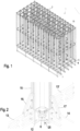
- FIG. 1 shows a highly schematic block storage arrangement 1 with a plurality of container receiving spaces 2 and a loading space 3 which is arranged below the container receiving spaces 2 in the direction of gravity.
- a passage opening 4 is arranged between each container receiving space 2 and the loading space 3 .
- the through hole 4 is formed in a frame 5 .
- the through-opening 4 has a 2 holding device 6 shown in more detail for a corner, which has a flap 7 which rotates about an axis 8 ( 3 ) is pivotable.
- the axis 8 is mounted in the frame 5, so that the flap 7 from one to the 2 , 3 and 5 shown holding position can be pivoted into a release position in which it points upwards in the direction of gravity.
- the axle 8 is mounted with its two ends in a bolt socket 9 which is open at the top in the direction of gravity.
- the flap 7 is biased by a spring 10 in the holding position.
- the spring 10 is in the form of a helical spring which is arranged on the end of the axle 8 .
- the bolt socket 9 is formed in a body 11 of an angle element 12 which is arranged at the corners of the through hole.
- the angle element 12 connects a longitudinal beam 13 and a cross beam 14 .
- a stand 15 is arranged on the angle element 12 .
- the stand 15 is connected to the longitudinal member 13 via a first strut arrangement 16 and to the cross member 14 via a second strut arrangement 17 . how to get in 2 can see, another longitudinal member 13 ′ of an adjacent passage opening 4 is arranged on the angle element 12 .
- the flap 7 shown would, if contacted from below by a container, be pushed out of the bolt socket 9, which is open at the top.
- an axle hold-down device 18 is provided, which 4 is shown from its side facing away from the through-opening 4 .
- the axle hold-down device 18 has two projections 19, 20 which, when the axle hold-down device 18 is mounted on the body 11, are arranged in the direction of gravity above the bolt socket 9 and act on the end of the axle 8. So when the axle hold-down device 18 is mounted on the body 11, the axle 8 of the flap 7 can no longer be pushed out of the bolt socket 9.
- the axle hold-down device 18 is fastened to the body 11 of the angle element 12 with the aid of four screws 21 (a different number of screws can also be provided).
- the body 11 has several screw holes 22, 23 for this purpose.
- the axle hold-down device 18 has a screw dome 24 for each screw, which allows the axle hold-down device 18 to be screwed to the body 11 even with a body 11 subject to tolerances, which can be designed as a cast part, for example, without the axle hold-down device 18 being strained.
- the axial hold-down device 18 has an insertion chamfer 25 at its lower end in the direction of gravity, which facilitates the threading of a container through the passage opening 4 .
- a corresponding insertion chamfer can also be formed at the upper end in the direction of gravity.
- the body 11 has a longitudinal extension 26 which is connected to the longitudinal member 13 and a transverse extension 27 which is connected to the cross member 14.
- the axle holding-down device 18 is connected both to the longitudinal extension 26 and to the transverse extension 27 .
- the axle holding-down device 18 thus has two flanks 28, 29 which are essentially aligned at right angles to one another.
- the angle element 12 has a positioning profile in a manner that is not shown in detail.
- the axle hold-down device 18 has a counter-profile 30 adapted thereto, so that the axle hold-down device 18 can be positioned very precisely on the body 11 of the angle element 12 in a repeatable manner.
- the axle hold-down device 18 has a recess 31 which is designed as a through opening.
- the recess 31 is adapted to the shape of the flap 7 . So if the flap, as in 6 shown, has been pivoted into the release position, then it fills the recess 31 largely. The flap 7 then closes with the side of the axle hold-down device 18 facing the through-opening 4 . In the release position, the flap 7 does not protrude beyond the side of the axial hold-down device 18 facing the through-opening 4 , so that a container cannot get caught on the flap 7 . With its side facing the through-opening 4 , the axle hold-down device 18 forms a sliding surface which enables a container to slide on the axle hold-down device 18 with little friction.
- the axle holding-down device 18 projects over both the longitudinal extension 26 in the direction of the longitudinal member 13 and the transverse extension 27 in the direction of the cross member 14 .
- a gap 32 which can be used to position the longitudinal beam 13 , thus results between two axle holding-down devices 18 , 18 ′, which are arranged on both sides of the longitudinal extension 26 .
- a gap 33 which can be used to position the transverse beam 14.
- the axle hold-down device 18 has an extension in the direction of gravity with which it covers the angle element 12 and thus the frame 5 in the direction of gravity. Therefore, when a container is inserted into or removed from a container receiving space 2, the container does not come into contact with the frame 5.
- the frame 5 can thus only be dimensioned with regard to its mechanical stability. The container is guided by the axle hold-down device 18 .
- the axle hold-down device 18 is designed as a plastic element.
- the side facing through-opening 4 can therefore be designed to be relatively smooth, which has a positive effect on the sliding properties of the sliding surface.
Landscapes
- Engineering & Computer Science (AREA)
- Mechanical Engineering (AREA)
- General Engineering & Computer Science (AREA)
- Physics & Mathematics (AREA)
- Mathematical Physics (AREA)
- Vehicle Step Arrangements And Article Storage (AREA)
- Warehouses Or Storage Devices (AREA)
- Packaging Of Annular Or Rod-Shaped Articles, Wearing Apparel, Cassettes, Or The Like (AREA)
- Stacking Of Articles And Auxiliary Devices (AREA)
- Road Paving Structures (AREA)
- Control Of Motors That Do Not Use Commutators (AREA)
- Stackable Containers (AREA)
- Apparatus For Radiation Diagnosis (AREA)
- Handcart (AREA)
- Details Of Rigid Or Semi-Rigid Containers (AREA)
Abstract
Description
- Die vorliegende Erfindung betrifft eine Blocklageranordnung mit mehreren Behälteraufnahmeräumen, einem in Schwerkraftrichtung unterhalb der Behälteraufnahmeräume angeordneten Beschickungsraum, jeweils einer Durchgangsöffnung zwischen den Behälteraufnahmeräumen und dem Beschickungsraum und einer in der Durchgangsöffnung angeordneten Halteeinrichtung, die eine um eine Achse zwischen einer Halteposition und einer Freigabeposition verschwenkbare Klappe aufweist, wobei die Achse im Rand der Durchgangsöffnung gelagert ist.
- Eine derartige Blocklageranordnung ist beispielsweise aus
EP 3 782 930 A1 bekannt. - Eine Blocklageranordnung, die auch als "Stapellageranordnung" bezeichnet werden kann, dient dazu, eine große Anzahl von Behältern in einem relativ geringem Raum unterzubringen. Die Behälter werden hierbei in Form von Stapeln aufgenommen, so dass sie in Schwerkraftrichtung dicht übereinander angeordnet werden können. Die Behälterstapel können in den Behälteraufnahmeräumen angeordnet sein. Die Behälteraufnahmeräume können in einer Ebene senkrecht zur Schwerkraftrichtung ebenfalls dicht benachbart zueinander angeordnet werden, so dass der zur Verfügung stehende Bauraum relativ gut ausgenutzt wird.
- Im vorliegenden Fall werden die Behälteraufnahmeräume in Schwerkraftrichtung von unten beschickt, d.h. ein Behälter wird von unten in einen Behälteraufnahmeraum eingebracht und auch nach unten aus dem Behälteraufnahmeraum entnommen.
- Hierzu wird ein Beschickungsfahrzeug verwendet, das im Beschickungsraum verfahrbar ist. Zum Einlagern eines Behälters in einen Behälteraufnahmeraum wird das Beschickungsfahrzeug mit dem darauf befindlichen Behälter in eine Position unterhalb des gewünschten Behälteraufnahmeraumes gefahren. Der Behälter wird dann durch das Beschickungsfahrzeug angehoben, bis er an der Halteeinrichtung vorbeigetreten ist. Wenn der Behälter dann durch das Beschickungsfahrzeug wieder abgesenkt wird, wird der Behälter in der Halteeinrichtung gehalten. Wenn sich bereits ein oder mehrere Behälter in dem betreffenden Behälterraum befunden haben, dann bildet der neu eingelagerte Behälter den untersten Behälter eines Behälterstapels.
- Zum Entnehmen eines Behälters aus dem Behälteraufnahmeraum wird ebenfalls das Beschickungsfahrzeug verwendet. Das Beschickungsfahrzeug wird unterhalb des Behälteraufnahmeraumes positioniert und eine Hubeinrichtung des Beschickungsfahrzeugs wird angehoben, bis sie den untersten Behälter mit anheben kann. Der Behälter, ggfs. mit weiteren darauf befindlichen Behältern, wird angehoben, bis er von der Halteeinrichtung freikommt. Die Halteeinrichtung wird dann in eine Freigabeposition gebracht und der Behälter kann abgesenkt werden. Beim Absenken wird die Halteeinrichtung wieder aktiviert, so dass der bislang vorletzte Behälter von der Halteeinrichtung gehalten wird. Wenn mehrere Behälter auf einmal aus dem Behälteraufnahmeraum entnommen werden sollen, kann die Halteeinrichtung auch erst dann aktiviert werden, wenn die gewünschte Anzahl von Behältern aus dem Behälteraufnahmeraum entnommen worden ist.
- Die Halteeinrichtung weist zum Halten eines Behälters eine oder mehrere Klappen auf, die zwischen einer Halteposition und einer Freigabeposition verschwenkbar sind. Zum Verschwenken weist die Klappe eine Achse auf, die am Rand der Durchgangsöffnung gelagert ist.
- Im Fall einer Beschädigung muss die Klappe leicht ausgewechselt werden können.
- Der Erfindung liegt die Aufgabe zugrunde, eine Blocklageranordnung auf einfache Weise wartungsfreundlich auszubilden.
- Diese Aufgabe wird bei einer Blocklageranordnung der eingangs genannten Art dadurch gelöst, dass die Achse an mindestens einem Ende in einer in Schwerkraftrichtung nach oben offenen Bolzenpfanne gelagert ist, wobei ein Achsniederhalter am Rand der Durchgangsöffnung befestigt ist, der zumindest teilweise in Schwerkraftrichtung oberhalb der Bolzenpfanne angeordnet ist und auf das Ende der Achse wirkt.
- Mit dieser Ausgestaltung kann die Klappe relativ einfach ausgewechselt werden oder es können auf einfache Weise Wartungsarbeiten an der Klappe vorgenommen werden, für die die Klappe insgesamt leicht zugänglich sein muss. Hierzu muss lediglich der Achsniederhalter aus der Durchgangsöffnung entfernt werden und die Achse der Klappe kann dann in Schwerkraftrichtung nach oben aus der Bolzenpfanne herausgenommen werden. Im Betrieb wird die Achse jedoch von dem Achsniederhalter in der Bolzenpfanne gehalten, so dass eine von unten auf die Klappe wirkende Kraft nicht dazu führt, dass die Klappe ihre vorbestimmte Position verlassen kann.
- Vorzugsweise ist die Klappe in einer Ecke der Durchgangsöffnung zwischen einer Längsseite und einer Querseite angeordnet und der Achsniederhalter ist sowohl mit der Längsseite als auch mit der Querseite verbunden. Der Achsniederhalter wird dadurch auf einfache Weise gegen ein Kippen gesichert, ohne dass für die Verbindung zwischen dem Achsniederhalter und dem Rand der Durchgangsöffnung ein übermäßig großer Aufwand betrieben werden muss.
- Vorzugsweise ist der Achsniederhalter mit dem Rand der Durchgangsöffnung mit Hilfe von Schrauben verbunden. Es können beispielsweise vier Schrauben vorgesehen sein, von denen jeweils zwei in der Längsseite und zwei in der Querseite befestigt sind. Die Verwendung von Schrauben ist eine relativ einfache Maßnahme.
- Vorzugsweise weist der Achsniederhalter für jede der Schrauben einen dem Rand der Durchgangsöffnung zugewandten Schraubdom auf. Ein Schraubdom ermöglicht auch bei toleranzbehafteten Elementen, die den Rand der Durchgangsöffnung bilden, ein Verschrauben ohne Verspannen der jeweiligen Teile. Das Risiko, dass sich der Achsniederhalter in unerwünschter Weise verformt, wird dadurch klein gehalten.
- Vorzugsweise ist die Klappe durch eine Feder in die Halteposition vorgespannt. Durch die Verwendung des Achsniederhalters kann man dann durchaus eine größere Vorspannkraft verwenden. Auch die Feder neigt gelegentlich dazu, die Achse der Klappe aus der Bolzenpfanne herauszudrücken. Dies wird durch den Achsniederhalter zuverlässig verhindert.
- Hierbei ist bevorzugt, dass die Feder als Schraubenfeder ausgebildet ist, die auf dem Ende der Achse angeordnet ist. Dies ist eine relativ einfache Möglichkeit, die Feder entsprechend zu positionieren.
- Vorzugsweise weist die Durchgangsöffnung ein Positionierprofil auf und der Achsniederhalter weist ein daran angepasstes Gegenprofil auf. Damit ist es auf einfache Weise möglich, den Achsniederhalter in der Durchgangsöffnung mit hoher Wiederholgenauigkeit an einer gewünschten Position zu positionieren.
- Bevorzugterweise ist der Achsniederhalter als Kunststoffelement ausgebildet. Der Achsniederhalter kann beispielsweise als Spritzgussteil ausgebildet sein. Der Achsniederhalter ist damit relativ kostengünstig.
- Vorzugsweise weist der Achsniederhalter in seinem in Schwerkraftrichtung unteren Ende eine Einführfase auf. Dies erleichtert es, einen Behälter von unten durch die Durchgangsöffnung in den Behälteraufnahmeraum einzuschieben. Die Einführfase ist dann in der Lage, kleine Ungenauigkeiten bei der Positionierung des Beschickungsfahrzeugs unterhalb des Behälteraufnahmeraums auszugleichen.
- Bevorzugterweise ist die Durchgangsöffnung in einem Rahmen ausgebildet, der zwischen den Behälteraufnahmeräumen und dem Beschickungsraum angeordnet ist, wobei die Achse in dem Rahmen gelagert ist. Der Rahmen trägt damit das Gewicht der Behälterstapel in den Behälteraufnahmeräumen. Der Rahmen kann auch dazu verwendet werden, Ständer zu montieren, die zwischen Behälteraufnahmeräumen angeordnet sind und eine Art Kippsicherung für die Behälterstapel bilden. Die Verwendung eines Rahmens ermöglicht es, die Durchgangsöffnung mit geringem Aufwand in Beziehung zu den jeweiligen Behälteraufnahmeräumen zu positionieren und die Form der Durchgangsöffnungen mit einer hohen Genauigkeit sicher zu stellen.
- Vorzugsweise weist der Achsniederhalter in Schwerkraftrichtung eine Erstreckung auf, mit der er den Rahmen in Schwerkraftrichtung überdeckt. Ein Behälter, der in einem Behälteraufnahmeraum eingelagert wird oder aus einem Behälteraufnahmeraum entnommen wird, kommt dann nicht in Kontakt mit dem Rahmen. Der Rahmen kann also ausschließlich im Hinblick auf eine mechanische Stabilität ausgebildet werden.
- Vorzugsweise weist der Achsniederhalter eine Ausnehmung auf, in der die Klappe in der Freigabeposition aufgenommen ist. Wenn sich die Klappe in der Freigabeposition befindet, dann steht sie nicht über den Achsniederhalter vor, so dass der Achsniederhalter gegenüber dem Behälter eine glatte Fläche bildet und ein Verhaken von Behälter und Klappe verhindert wird. Besonders bevorzugt ist, dass die Klappe in der Freigabestellung mit der der Durchgangsöffnung zugewandten Seite des Achsniederhalters abschließt.
- Vorzugsweise bildet der Achsniederhalter auf seiner der Durchgangsöffnung zugewandten Seite eine Gleitfläche. Die Gleitfläche ist glatt ausgebildet, was sich bei Verwendung eines Kunststoffteils relativ leicht realisieren lässt. Die Gleitfläche erleichtert es einem Behälter, an dem Achsniederhalter entlangzugleiten.
- Vorzugsweise weist der Rahmen Längsträger und Querträger auf, die durch Winkelelemente miteinander verbunden sind, wobei der Achsniederhalter an einem Winkelelement befestigt ist und der Achsniederhalter über das Winkelelement in Richtung auf den am Winkelelement befestigten Längsträger und/oder Querträger vorsteht. Der Achsniederhalter bildet damit gleichzeitig eine Positionierhilfe für den Längsträger und/oder den Querträger. Wenn am Winkelelement ein Längsträger und/oder ein Querträger befestigt ist und ein Achsniederhalter auf beiden Seiten des Längsträgers und/oder des Querträgers angeordnet ist, dann bilden die beiden Achsniederhalter eine Nut, in die der Längsträger bzw. der Querträger eingesetzt werden kann.
- Die Erfindung wird im Folgenden anhand eines bevorzugten Ausführungsbeispiels in Verbindung mit der Zeichnung beschrieben. Hierin zeigen:
- Fig. 1
- eine stark schematisierte Darstellung einer Blocklageranordnung,
- Fig. 2
- eine Ecke einer Durchgangsöffnung,
- Fig. 3
- die Ecke der Durchgangsöffnung ohne Achsniederhalter,
- Fig. 4
- einen Achsniederhalter von seiner der Durchgangsöffnung abgewandten Seite,
- Fig. 5
- ein Winkelelement mit vier Achsniederhaltern und
- Fig. 6
- eine schematische Darstellung zur Erläuterung der Funktion des Achsniederhalters.
-
Fig. 1 zeigt stark schematisiert eine Blocklageranordnung 1 mit mehreren Behälteraufnahmeräumen 2 und einem Beschickungsraum 3, der in Schwerkraftrichtung unterhalb der Behälteraufnahmeräume 2 angeordnet ist. - Zwischen jedem Behälteraufnahmeraum 2 und dem Beschickungsraum 3 ist eine Durchgangsöffnung 4 angeordnet. Die Durchgangsöffnung 4 ist in einem Rahmen 5 ausgebildet. Die Durchgangsöffnung 4 weist eine in
Fig. 2 für eine Ecke näher dargestellte Halteeinrichtung 6 auf, die eine Klappe 7 aufweist, die um eine Achse 8 (Fig. 3 ) verschwenkbar ist. Die Achse 8 ist im Rahmen 5 gelagert, so dass die Klappe 7 aus einer in denFig. 2 ,3 und5 dargestellte Halteposition in eine Freigabeposition verschwenkbar ist, in der sie in Schwerkraftrichtung nach oben weist. - Die Achse 8 ist mit ihren beiden Enden in einer in Schwerkraftrichtung nach oben offenen Bolzenpfanne 9 gelagert. Die Klappe 7 ist durch eine Feder 10 in die Halteposition vorgespannt. Die Feder 10 ist als Schraubenfeder ausgebildet, die auf dem Ende der Achse 8 angeordnet ist.
- Die Bolzenpfanne 9 ist in einem Korpus 11 eines Winkelelements 12 ausgebildet, das an den Ecken der Durchgangsöffnung angeordnet ist. Das Winkelelement 12 verbindet einen Längsträger 13 und einen Querträger 14. Der Längsträger 13 ist an einer Längsseite der Durchgangsöffnung 4 angeordnet und der Querträger 14 ist an einer Querseite der Durchgangsöffnung 4 angeordnet.
- Auf dem Winkelelement 12 ist ein Ständer 15 angeordnet. Der Ständer 15 ist mit dem Längsträger 13 über eine erste Strebenanordnung 16 und mit dem Querträger 14 über eine zweite Strebenanordnung 17 verbunden. Wie man in
Fig. 2 erkennen kann, ist an dem Winkelelement 12 noch ein weiterer Längsträger 13' einer benachbarten Durchgangsöffnung 4 angeordnet. - Die in
Fig. 3 dargestellte Klappe 7 würde, wenn sie von unten von einem Behälter kontaktiert wird, aus der nach oben offenen Bolzenpfanne 9 herausgedrückt werden. Um dies zu verhindern, ist ein Achsniederhalter 18 vorgesehen, der inFig. 4 von seiner der Durchgangsöffnung 4 abgewandten Seite dargestellt ist. Der Achsniederhalter 18 weist zwei Vorsprünge 19, 20 auf, die, wenn der Achsniederhalter 18 am Korpus 11 montiert ist, in Schwerkraftrichtung oberhalb der Bolzenpfanne 9 angeordnet sind und auf das Ende der Achse 8 wirken. Wenn also der Achsniederhalter 18 am Korpus 11 montiert ist, kann die Achse 8 der Klappe 7 nicht mehr aus der Bolzenpfanne 9 herausgedrückt werden. - Der Achsniederhalter 18 ist mit Hilfe von vier Schrauben 21 (es können auch eine andere Anzahl von Schrauben vorgesehen sein) am Korpus 11 des Winkelelements 12 befestigt. Hierzu weist der Korpus 11 mehrere Schraubenlöcher 22, 23 auf. Der Achsniederhalter 18 weist für jede Schraube einen Schraubdom 24 auf, der auch bei einem toleranzbehafteten Korpus 11, der z.B. als Gussteil ausgebildet sein kann, ein Verschrauben des Achsniederhalters 18 mit dem Korpus 11 ermöglicht, ohne dass der Achsniederhalter 18 verspannt wird.
- Der Achsniederhalter 18 weist an seinem in Schwerkraftrichtung unteren Ende eine Einführfase 25 auf, die das Einfädeln eines Behälters durch die Durchgangsöffnung 4 erleichtert. Eine entsprechende Einführfase kann auch am in Schwerkraftrichtung oberen Ende ausgebildet sein.
- Der Korpus 11 weist einen Längsfortsatz 26 auf, der mit dem Längsträger 13 verbunden ist, und einen Querfortsatz 27, der mit dem Querträger 14 verbunden ist. Der Achsniederhalter 18 ist sowohl mit dem Längsfortsatz 26 als auch mit dem Querfortsatz 27 verbunden. Der Achsniederhalter 18 weist also zwei Flanken 28, 29 auf, die im Wesentlichen unter einem rechten Winkel zueinander ausgerichtet sind.
- Das Winkelelement 12 weist in nicht näher dargestellter Weise ein Positionierprofil auf. Der Achsniederhalter 18 weist ein daran angepasstes Gegenprofil 30 auf, so dass der Achsniederhalter 18 wiederholbar sehr genau am Korpus 11 des Winkelelements 12 positioniert werden kann.
- Der Achsniederhalter 18 weist eine Ausnehmung 31 auf, die als Durchgangsöffnung ausgebildet ist. Die Ausnehmung 31 ist an die Form der Klappe 7 angepasst. Wenn also die Klappe, wie in
Fig. 6 dargestellt, in die Freigabeposition verschwenkt worden ist, dann füllt sie die Ausnehmung 31 weitgehend aus. Die Klappe 7 schließt dann mit der der Durchgangsöffnung 4 zugewandten Seite des Achsniederhalters 18 ab. In der Freigabeposition steht die Klappe 7 also nicht über die der Durchgangsöffnung 4 zugewandten Seite des Achsniederhalters 18 über, so dass ein Behälter nicht an der Klappe 7 hängen bleiben kann. Der Achsniederhalter 18 bildet mit seiner der Durchgangsöffnung 4 zugewandten Seite eine Gleitfläche, die ein reibungsarmes gleiten eines Behälters am Achsniederhalter 18 ermöglicht. - Wie man in
Fig. 5 erkennen kann, steht der Achsniederhalter 18 sowohl über den Längsfortsatz 26 in Richtung auf den Längsträger 13 als auch über den Querfortsatz 27 in Richtung auf den Querträger 14 über. Zwischen zwei Achsniederhaltern 18, 18', die auf beiden Seiten des Längsfortsatzes 26 angeordnet sind, ergibt sich damit ein Spalt 32, der zur Positionierung des Längsträgers 13 verwendet werden kann. In gleicher Weise ergibt sich zwischen zwei Achsniederhaltern 18, 18", die am Querfortsatz 27 montiert sind, ein Spalt 33, der zur Positionierung des Querträgers 14 verwendet werden kann. - Der Achsniederhalter 18 weist in Schwerkraftrichtung eine Erstreckung auf, mit der er das Winkelelement 12 und damit den Rahmen 5 in Schwerkraftrichtung überdeckt. Wenn also ein Behälter in einen Behälteraufnahmeraum 2 eingeführt oder von dort entnommen wird, kommt der Behälter mit dem Rahmen 5 nicht in Kontakt. Der Rahmen 5 kann damit ausschließlich im Hinblick auf seine mechanische Stabilität hin dimensioniert werden. Die Führung des Behälters wird durch den Achsniederhalter 18 übernommen.
- Der Achsniederhalter 18 ist als Kunststoffelement ausgebildet. Die der Durchgangsöffnung 4 zugewandte Seite kann daher relativ glatt ausgebildet sein, was sich positiv auf die Gleiteigenschaften der Gleitfläche auswirkt.
Claims (14)
- Blocklageranordnung mit mehreren Behälteraufnahmeräumen (2), einem in Schwerkraftrichtung unterhalb der Behälteraufnahmeräumen (2) angeordneten Beschickungsraum (3), jeweils einer Durchgangsöffnung (4) zwischen den Behälteraufnahmeräumen (2) und dem Beschickungsraum (3) und einer in der Durchgangsöffnung angeordneten Halteeinrichtung, die eine um eine Achse (8) zwischen einer Halteposition und einer Freigabeposition verschwenkbare Klappe (7) aufweist, wobei die Achse (8) im Rand der Durchgangsöffnung (4) gelagert ist, dadurch gekennzeichnet, dass die Achse (8) an mindestens einem Ende in einer in Schwerkraftrichtung nach oben offenen Bolzenpfanne (9) gelagert ist, wobei ein Achsniederhalter (18) am Rand der Durchgangsöffnung (4) befestigt ist, der zumindest teilweise in Schwerkraftrichtung oberhalb der Bolzenpfanne (9) angeordnet ist und auf das Ende der Achse (8) wirkt.
- Blocklageranordnung nach Anspruch 1, dadurch gekennzeichnet, dass die Klappe (7) in einer Ecke der Durchgangsöffnung (4) zwischen einer Längsseite und einer Querseite angeordnet ist und der Achsniederhalter (18) sowohl mit der Längsseite als auch mit der Querseite verbunden ist.
- Blocklageranordnung nach Anspruch 2, dadurch gekennzeichnet, dass der Achsniederhalter (18) mit dem Rand der Durchgangsöffnung (4) mit Hilfe von Schrauben (21) verbunden ist.
- Blocklageranordnung nach Anspruch 3, dadurch gekennzeichnet, dass der Achsniederhalter (18) für jede der Schrauben (21) einen dem Rand der Durchgangsöffnung (4) zugewandten Schraubdom (24) aufweist.
- Blocklageranordnung nach einem der Ansprüche 1 bis 4, dadurch gekennzeichnet, dass die Klappe (7) durch eine Feder (10) in die Halteposition vorgespannt ist.
- Blocklageranordnung nach Anspruch 5, dadurch gekennzeichnet, dass die Feder (10) als Schraubenfeder ausgebildet ist, die auf dem Ende der Achse (8) angeordnet ist.
- Blocklageranordnung nach einem der Ansprüche 1 bis 6, dadurch gekennzeichnet, dass die Durchgangsöffnung (4) ein Positionierprofil aufweist und der Achsniederhalter (18) ein daran angepasstes Gegenprofil (31) aufweist.
- Blocklageranordnung nach einem der Ansprüche 1 bis 7, dadurch gekennzeichnet, dass der Achsniederhalter (18) als Kunststoffelement ausgebildet ist.
- Blocklageranordnung nach einem der Ansprüche 1 bis 8, dadurch gekennzeichnet, dass der Achsniederhalter (18) an seinem in Schwerkraftrichtung unteren Ende eine Einführfase (25) aufweist.
- Blocklageranordnung nach einem der Ansprüche 1 bis 9, dadurch gekennzeichnet, dass die Durchgangsöffnung (4) in einem Rahmen (5) ausgebildet ist, der zwischen den Behälteraufnahmeräumen (2) und dem Beschickungsraum (3) angeordnet ist, wobei die Achse (8) in dem Rahmen (5) gelagert ist.
- Blocklageranordnung nach Anspruch 10, dadurch gekennzeichnet, dass der Achsniederhalter (18) in Schwerkraftrichtung eine Erstreckung aufweist, mit der er den Rahmen (5) in Schwerkraftrichtung überdeckt.
- Blocklageranordnung nach Anspruch 11, dadurch gekennzeichnet, dass der Achsniederhalter (18) eine Ausnehmung (31) aufweist, in der die Klappe (7) in der Freigabeposition aufgenommen ist.
- Blocklageranordnung nach einem der Ansprüche 10 bis 12, dadurch gekennzeichnet, dass der Achsniederhalter (18) auf seiner der Durchgangsöffnung (4) zugewandten Seite eine Gleitfläche bildet.
- Blocklageranordnung nach einem der Ansprüche 1 bis 12, dadurch gekennzeichnet, dass der Rahmen (5) Längsträger (13,13') und Querträger (14) aufweist, die durch Winkelelemente (12) miteinander verbunden sind, wobei der Achsniederhalter (18) an einem Winkelelement (12) befestigt ist und der Achsniederhalter (18) über das Winkelelement (12) in Richtung auf den am Winkelelement (12) befestigten Längsträger (13, 13') und/oder Querträger (14) vorsteht.
Priority Applications (9)
| Application Number | Priority Date | Filing Date | Title |
|---|---|---|---|
| ES22159994T ES2993416T3 (en) | 2022-03-03 | 2022-03-03 | Block storage arrangement |
| EP22159994.7A EP4238895B1 (de) | 2022-03-03 | 2022-03-03 | Blocklageranordnung |
| PL22159994.7T PL4238895T3 (pl) | 2022-03-03 | 2022-03-03 | Układ składowania blokowego |
| AU2023201085A AU2023201085A1 (en) | 2022-03-03 | 2023-02-23 | Block stacking arrangement |
| KR1020230025359A KR20230130546A (ko) | 2022-03-03 | 2023-02-24 | 블록 적층 배열 |
| CN202310183483.2A CN116692346A (zh) | 2022-03-03 | 2023-03-01 | 块堆叠装置 |
| US18/115,930 US12110184B2 (en) | 2022-03-03 | 2023-03-01 | Block stacking arrangement |
| JP2023031492A JP2023129355A (ja) | 2022-03-03 | 2023-03-02 | ブロック積み重ね構成 |
| CA3191881A CA3191881A1 (en) | 2022-03-03 | 2023-03-03 | Block stacking arrangement |
Applications Claiming Priority (1)
| Application Number | Priority Date | Filing Date | Title |
|---|---|---|---|
| EP22159994.7A EP4238895B1 (de) | 2022-03-03 | 2022-03-03 | Blocklageranordnung |
Publications (2)
| Publication Number | Publication Date |
|---|---|
| EP4238895A1 true EP4238895A1 (de) | 2023-09-06 |
| EP4238895B1 EP4238895B1 (de) | 2024-07-10 |
Family
ID=80628951
Family Applications (1)
| Application Number | Title | Priority Date | Filing Date |
|---|---|---|---|
| EP22159994.7A Active EP4238895B1 (de) | 2022-03-03 | 2022-03-03 | Blocklageranordnung |
Country Status (9)
| Country | Link |
|---|---|
| US (1) | US12110184B2 (de) |
| EP (1) | EP4238895B1 (de) |
| JP (1) | JP2023129355A (de) |
| KR (1) | KR20230130546A (de) |
| CN (1) | CN116692346A (de) |
| AU (1) | AU2023201085A1 (de) |
| CA (1) | CA3191881A1 (de) |
| ES (1) | ES2993416T3 (de) |
| PL (1) | PL4238895T3 (de) |
Cited By (2)
| Publication number | Priority date | Publication date | Assignee | Title |
|---|---|---|---|---|
| EP4588852A1 (de) * | 2024-01-22 | 2025-07-23 | Autostore Technology As | Lager- und wiederauffindungssystem |
| EP4703298A1 (de) | 2024-08-28 | 2026-03-04 | Jungheinrich AG | Lageranordnung mit einem blocklager und einer behälterauf- und -abgabestation |
Families Citing this family (4)
| Publication number | Priority date | Publication date | Assignee | Title |
|---|---|---|---|---|
| NO346601B1 (en) * | 2021-02-08 | 2022-10-24 | Autostore Tech As | Grid Survey Module |
| ES3037374T3 (en) * | 2022-03-03 | 2025-10-01 | Jungheinrich Ag | Block storage arrangement |
| PL4296205T3 (pl) * | 2022-06-22 | 2025-06-23 | Jungheinrich Aktiengesellschaft | Układ składowania w stosach i sposób obsługi układu składowania w stosach |
| EP4733225A1 (de) * | 2024-10-23 | 2026-04-29 | AutoStore Technology AS | Zellblockierungsvorrichtung |
Citations (3)
| Publication number | Priority date | Publication date | Assignee | Title |
|---|---|---|---|---|
| DE19849391A1 (de) * | 1998-10-27 | 2000-05-11 | Josef Basic | Kistenstapellager |
| DE102016125786A1 (de) * | 2016-12-28 | 2018-06-28 | Extor Gmbh | Lagersystem für Behälter sowie Behälter dafür |
| EP3782930A1 (de) | 2019-08-23 | 2021-02-24 | Jungheinrich Aktiengesellschaft | Stapellageranordnung |
Family Cites Families (16)
| Publication number | Priority date | Publication date | Assignee | Title |
|---|---|---|---|---|
| US3231103A (en) * | 1962-09-10 | 1966-01-25 | Fruehauf Corp | Container stacking system |
| US6481177B1 (en) * | 2000-10-27 | 2002-11-19 | 80/20, Inc. | Inside corner connector for structural framing members |
| KR100846399B1 (ko) * | 2000-12-13 | 2008-07-16 | 엔티그리스 케이먼 리미티드 | Foup 도어가 foup 내로 부적절하게 삽입되는 것을방지하는 시스템 |
| JP2003292118A (ja) * | 2002-04-05 | 2003-10-15 | Murata Mach Ltd | 自動倉庫 |
| JP5815677B2 (ja) * | 2010-04-26 | 2015-11-17 | ブランキング システムズ インクBlanking Systems, Inc. | 構造体のためのフレーム部材 |
| US20140308107A1 (en) * | 2013-04-12 | 2014-10-16 | Michael Nickles | Last-in, first-out bottom-loading, bottom-deloading vertical storage and retrieval system and method of manufacture |
| US10336540B2 (en) * | 2015-04-27 | 2019-07-02 | Attabotics Inc. | Storage and retrieval system |
| NO344465B1 (en) * | 2017-10-20 | 2019-12-23 | Autostore Tech As | Bin holding Device and method of arranging a top edge of a storage bin at a predetermined level in the bin holding device |
| JP7300468B2 (ja) * | 2018-06-08 | 2023-06-29 | アタボティックス インコーポレイテッド | 保管格子と外部作業ステーションとの間で共通ロボット車両隊を共有する保管及び回収システム |
| EP3782928B1 (de) * | 2019-08-23 | 2022-11-23 | Jungheinrich Aktiengesellschaft | Stapellageranordnung |
| ES3031992T3 (en) * | 2019-08-23 | 2025-07-14 | Jungheinrich Ag | Stack storage assembly |
| EP3782929A1 (de) * | 2019-08-23 | 2021-02-24 | Jungheinrich Aktiengesellschaft | Behälterstapellager-beschickungswagen |
| EP3838802B1 (de) * | 2019-12-19 | 2024-07-03 | Jungheinrich Aktiengesellschaft | Stapellageranordnung und verfahren zum betreiben einer stapellageranordnung |
| ES2980861T3 (es) * | 2020-08-26 | 2024-10-03 | Jungheinrich Ag | Disposición de almacenamiento por apilado |
| ES3033102T3 (en) * | 2022-03-03 | 2025-07-30 | Jungheinrich Ag | Stack storage assembly |
| ES3034274T3 (en) * | 2022-03-03 | 2025-08-14 | Jungheinrich Ag | Block storage arrangement |
-
2022
- 2022-03-03 ES ES22159994T patent/ES2993416T3/es active Active
- 2022-03-03 EP EP22159994.7A patent/EP4238895B1/de active Active
- 2022-03-03 PL PL22159994.7T patent/PL4238895T3/pl unknown
-
2023
- 2023-02-23 AU AU2023201085A patent/AU2023201085A1/en active Pending
- 2023-02-24 KR KR1020230025359A patent/KR20230130546A/ko active Pending
- 2023-03-01 US US18/115,930 patent/US12110184B2/en active Active
- 2023-03-01 CN CN202310183483.2A patent/CN116692346A/zh active Pending
- 2023-03-02 JP JP2023031492A patent/JP2023129355A/ja active Pending
- 2023-03-03 CA CA3191881A patent/CA3191881A1/en active Pending
Patent Citations (3)
| Publication number | Priority date | Publication date | Assignee | Title |
|---|---|---|---|---|
| DE19849391A1 (de) * | 1998-10-27 | 2000-05-11 | Josef Basic | Kistenstapellager |
| DE102016125786A1 (de) * | 2016-12-28 | 2018-06-28 | Extor Gmbh | Lagersystem für Behälter sowie Behälter dafür |
| EP3782930A1 (de) | 2019-08-23 | 2021-02-24 | Jungheinrich Aktiengesellschaft | Stapellageranordnung |
Cited By (4)
| Publication number | Priority date | Publication date | Assignee | Title |
|---|---|---|---|---|
| EP4588852A1 (de) * | 2024-01-22 | 2025-07-23 | Autostore Technology As | Lager- und wiederauffindungssystem |
| WO2025157537A1 (en) * | 2024-01-22 | 2025-07-31 | Autostore Technology AS | A storage and retrieval system |
| EP4703298A1 (de) | 2024-08-28 | 2026-03-04 | Jungheinrich AG | Lageranordnung mit einem blocklager und einer behälterauf- und -abgabestation |
| DE102024124566A1 (de) | 2024-08-28 | 2026-03-05 | Jungheinrich Aktiengesellschaft | Lageranordnung mit einem Blocklager und einer Behälterauf- und -abgabestation |
Also Published As
| Publication number | Publication date |
|---|---|
| KR20230130546A (ko) | 2023-09-12 |
| JP2023129355A (ja) | 2023-09-14 |
| CA3191881A1 (en) | 2023-09-03 |
| US12110184B2 (en) | 2024-10-08 |
| ES2993416T3 (en) | 2024-12-30 |
| US20230278801A1 (en) | 2023-09-07 |
| PL4238895T3 (pl) | 2024-10-28 |
| CN116692346A (zh) | 2023-09-05 |
| AU2023201085A1 (en) | 2023-09-21 |
| EP4238895B1 (de) | 2024-07-10 |
Similar Documents
| Publication | Publication Date | Title |
|---|---|---|
| EP4238895B1 (de) | Blocklageranordnung | |
| EP3782931B1 (de) | Stapellageranordnung | |
| EP3960657B1 (de) | Stapellageranordnung | |
| EP3782930A1 (de) | Stapellageranordnung | |
| DE3627169A1 (de) | Lineare waelzkoerperfuehrung | |
| EP0753457A2 (de) | Riegelelement | |
| DE102022102004A1 (de) | Fixiervorrichtung für einen Behälter und System zum Verarbeiten von Behältern | |
| DE29803921U1 (de) | Stapelsäule zur Aufnahme einer Vielzahl von flächigen Werkstücken | |
| DE102008061204B3 (de) | Magazin zur Lagerung von Twist-Locks | |
| EP1856417A1 (de) | Hochlastbeschlag zum verbinden von zwei bauteilen | |
| EP4296205A1 (de) | Blocklageranordnung und verfahren zum betreiben einer blocklageranordnung | |
| DE112008001364T5 (de) | Verbinder für Fluiddruckvorrichtungen | |
| EP4238897A1 (de) | Blocklageranordnung | |
| DE102016222096B4 (de) | Fahrzeugklappenanordnung und damit ausgestattetes kraftfahrzeug | |
| DE202008008417U1 (de) | Verriegelung zum Verriegeln eines Containers auf einer Auflage | |
| EP4428034B1 (de) | Seitenführung und frachtdeck eines flugzeugs | |
| DE9318410U1 (de) | Klinkenturm | |
| EP0215328B1 (de) | Vorrichtung zum Lagern von Teilen im Abstand zueinander, insbesondere zum Lagern von Blechen oder Blechformteilen | |
| DE3536215C2 (de) | ||
| DE102022203186A1 (de) | Testadapter zum Testen einer elektrischen Baugruppe oder eines elektrischen Bauteils | |
| DE69300879T2 (de) | Vorrichtung zum Halten eines Containers auf einer Kraftfahrzeugplattform und Kraftfahrzeuge mit einer solchen Vorrichtung. | |
| DE20214308U1 (de) | Montagevorrichtung | |
| DE102025123928B3 (de) | Schwerlast-Stapelsäule zur Aufnahme von Schwerlastgütern | |
| DE69110597T2 (de) | Stützbalken für die Ladung. | |
| DE202015106985U1 (de) | Nutzentrennwerkzeug |
Legal Events
| Date | Code | Title | Description |
|---|---|---|---|
| PUAI | Public reference made under article 153(3) epc to a published international application that has entered the european phase |
Free format text: ORIGINAL CODE: 0009012 |
|
| STAA | Information on the status of an ep patent application or granted ep patent |
Free format text: STATUS: REQUEST FOR EXAMINATION WAS MADE |
|
| 17P | Request for examination filed |
Effective date: 20221028 |
|
| AK | Designated contracting states |
Kind code of ref document: A1 Designated state(s): AL AT BE BG CH CY CZ DE DK EE ES FI FR GB GR HR HU IE IS IT LI LT LU LV MC MK MT NL NO PL PT RO RS SE SI SK SM TR |
|
| GRAP | Despatch of communication of intention to grant a patent |
Free format text: ORIGINAL CODE: EPIDOSNIGR1 |
|
| STAA | Information on the status of an ep patent application or granted ep patent |
Free format text: STATUS: GRANT OF PATENT IS INTENDED |
|
| RIC1 | Information provided on ipc code assigned before grant |
Ipc: B65G 57/30 20060101ALI20240115BHEP Ipc: B65G 1/04 20060101AFI20240115BHEP |
|
| INTG | Intention to grant announced |
Effective date: 20240216 |
|
| GRAS | Grant fee paid |
Free format text: ORIGINAL CODE: EPIDOSNIGR3 |
|
| GRAA | (expected) grant |
Free format text: ORIGINAL CODE: 0009210 |
|
| STAA | Information on the status of an ep patent application or granted ep patent |
Free format text: STATUS: THE PATENT HAS BEEN GRANTED |
|
| P01 | Opt-out of the competence of the unified patent court (upc) registered |
Effective date: 20240527 |
|
| AK | Designated contracting states |
Kind code of ref document: B1 Designated state(s): AL AT BE BG CH CY CZ DE DK EE ES FI FR GB GR HR HU IE IS IT LI LT LU LV MC MK MT NL NO PL PT RO RS SE SI SK SM TR |
|
| REG | Reference to a national code |
Ref country code: CH Ref legal event code: EP |
|
| REG | Reference to a national code |
Ref country code: DE Ref legal event code: R096 Ref document number: 502022001190 Country of ref document: DE |
|
| REG | Reference to a national code |
Ref country code: NL Ref legal event code: FP |
|
| REG | Reference to a national code |
Ref country code: LT Ref legal event code: MG9D |
|
| PG25 | Lapsed in a contracting state [announced via postgrant information from national office to epo] |
Ref country code: PT Free format text: LAPSE BECAUSE OF FAILURE TO SUBMIT A TRANSLATION OF THE DESCRIPTION OR TO PAY THE FEE WITHIN THE PRESCRIBED TIME-LIMIT Effective date: 20241111 |
|
| REG | Reference to a national code |
Ref country code: ES Ref legal event code: FG2A Ref document number: 2993416 Country of ref document: ES Kind code of ref document: T3 Effective date: 20241230 |
|
| PG25 | Lapsed in a contracting state [announced via postgrant information from national office to epo] |
Ref country code: PT Free format text: LAPSE BECAUSE OF FAILURE TO SUBMIT A TRANSLATION OF THE DESCRIPTION OR TO PAY THE FEE WITHIN THE PRESCRIBED TIME-LIMIT Effective date: 20241111 |
|
| PG25 | Lapsed in a contracting state [announced via postgrant information from national office to epo] |
Ref country code: GR Free format text: LAPSE BECAUSE OF FAILURE TO SUBMIT A TRANSLATION OF THE DESCRIPTION OR TO PAY THE FEE WITHIN THE PRESCRIBED TIME-LIMIT Effective date: 20241011 Ref country code: FI Free format text: LAPSE BECAUSE OF FAILURE TO SUBMIT A TRANSLATION OF THE DESCRIPTION OR TO PAY THE FEE WITHIN THE PRESCRIBED TIME-LIMIT Effective date: 20240710 |
|
| PG25 | Lapsed in a contracting state [announced via postgrant information from national office to epo] |
Ref country code: BG Free format text: LAPSE BECAUSE OF FAILURE TO SUBMIT A TRANSLATION OF THE DESCRIPTION OR TO PAY THE FEE WITHIN THE PRESCRIBED TIME-LIMIT Effective date: 20240710 |
|
| PG25 | Lapsed in a contracting state [announced via postgrant information from national office to epo] |
Ref country code: LV Free format text: LAPSE BECAUSE OF FAILURE TO SUBMIT A TRANSLATION OF THE DESCRIPTION OR TO PAY THE FEE WITHIN THE PRESCRIBED TIME-LIMIT Effective date: 20240710 |
|
| PG25 | Lapsed in a contracting state [announced via postgrant information from national office to epo] |
Ref country code: IS Free format text: LAPSE BECAUSE OF FAILURE TO SUBMIT A TRANSLATION OF THE DESCRIPTION OR TO PAY THE FEE WITHIN THE PRESCRIBED TIME-LIMIT Effective date: 20241110 |
|
| PG25 | Lapsed in a contracting state [announced via postgrant information from national office to epo] |
Ref country code: HR Free format text: LAPSE BECAUSE OF FAILURE TO SUBMIT A TRANSLATION OF THE DESCRIPTION OR TO PAY THE FEE WITHIN THE PRESCRIBED TIME-LIMIT Effective date: 20240710 |
|
| PG25 | Lapsed in a contracting state [announced via postgrant information from national office to epo] |
Ref country code: RS Free format text: LAPSE BECAUSE OF FAILURE TO SUBMIT A TRANSLATION OF THE DESCRIPTION OR TO PAY THE FEE WITHIN THE PRESCRIBED TIME-LIMIT Effective date: 20241010 |
|
| PG25 | Lapsed in a contracting state [announced via postgrant information from national office to epo] |
Ref country code: RS Free format text: LAPSE BECAUSE OF FAILURE TO SUBMIT A TRANSLATION OF THE DESCRIPTION OR TO PAY THE FEE WITHIN THE PRESCRIBED TIME-LIMIT Effective date: 20241010 Ref country code: LV Free format text: LAPSE BECAUSE OF FAILURE TO SUBMIT A TRANSLATION OF THE DESCRIPTION OR TO PAY THE FEE WITHIN THE PRESCRIBED TIME-LIMIT Effective date: 20240710 Ref country code: IS Free format text: LAPSE BECAUSE OF FAILURE TO SUBMIT A TRANSLATION OF THE DESCRIPTION OR TO PAY THE FEE WITHIN THE PRESCRIBED TIME-LIMIT Effective date: 20241110 Ref country code: HR Free format text: LAPSE BECAUSE OF FAILURE TO SUBMIT A TRANSLATION OF THE DESCRIPTION OR TO PAY THE FEE WITHIN THE PRESCRIBED TIME-LIMIT Effective date: 20240710 Ref country code: GR Free format text: LAPSE BECAUSE OF FAILURE TO SUBMIT A TRANSLATION OF THE DESCRIPTION OR TO PAY THE FEE WITHIN THE PRESCRIBED TIME-LIMIT Effective date: 20241011 Ref country code: FI Free format text: LAPSE BECAUSE OF FAILURE TO SUBMIT A TRANSLATION OF THE DESCRIPTION OR TO PAY THE FEE WITHIN THE PRESCRIBED TIME-LIMIT Effective date: 20240710 Ref country code: BG Free format text: LAPSE BECAUSE OF FAILURE TO SUBMIT A TRANSLATION OF THE DESCRIPTION OR TO PAY THE FEE WITHIN THE PRESCRIBED TIME-LIMIT Effective date: 20240710 |
|
| REG | Reference to a national code |
Ref country code: DE Ref legal event code: R097 Ref document number: 502022001190 Country of ref document: DE |
|
| PG25 | Lapsed in a contracting state [announced via postgrant information from national office to epo] |
Ref country code: RO Free format text: LAPSE BECAUSE OF FAILURE TO SUBMIT A TRANSLATION OF THE DESCRIPTION OR TO PAY THE FEE WITHIN THE PRESCRIBED TIME-LIMIT Effective date: 20240710 Ref country code: SM Free format text: LAPSE BECAUSE OF FAILURE TO SUBMIT A TRANSLATION OF THE DESCRIPTION OR TO PAY THE FEE WITHIN THE PRESCRIBED TIME-LIMIT Effective date: 20240710 Ref country code: DK Free format text: LAPSE BECAUSE OF FAILURE TO SUBMIT A TRANSLATION OF THE DESCRIPTION OR TO PAY THE FEE WITHIN THE PRESCRIBED TIME-LIMIT Effective date: 20240710 |
|
| PG25 | Lapsed in a contracting state [announced via postgrant information from national office to epo] |
Ref country code: EE Free format text: LAPSE BECAUSE OF FAILURE TO SUBMIT A TRANSLATION OF THE DESCRIPTION OR TO PAY THE FEE WITHIN THE PRESCRIBED TIME-LIMIT Effective date: 20240710 |
|
| PG25 | Lapsed in a contracting state [announced via postgrant information from national office to epo] |
Ref country code: SK Free format text: LAPSE BECAUSE OF FAILURE TO SUBMIT A TRANSLATION OF THE DESCRIPTION OR TO PAY THE FEE WITHIN THE PRESCRIBED TIME-LIMIT Effective date: 20240710 |
|
| PLBE | No opposition filed within time limit |
Free format text: ORIGINAL CODE: 0009261 |
|
| STAA | Information on the status of an ep patent application or granted ep patent |
Free format text: STATUS: NO OPPOSITION FILED WITHIN TIME LIMIT |
|
| 26N | No opposition filed |
Effective date: 20250411 |
|
| PG25 | Lapsed in a contracting state [announced via postgrant information from national office to epo] |
Ref country code: SE Free format text: LAPSE BECAUSE OF FAILURE TO SUBMIT A TRANSLATION OF THE DESCRIPTION OR TO PAY THE FEE WITHIN THE PRESCRIBED TIME-LIMIT Effective date: 20240710 |
|
| PG25 | Lapsed in a contracting state [announced via postgrant information from national office to epo] |
Ref country code: MC Free format text: LAPSE BECAUSE OF FAILURE TO SUBMIT A TRANSLATION OF THE DESCRIPTION OR TO PAY THE FEE WITHIN THE PRESCRIBED TIME-LIMIT Effective date: 20240710 |
|
| PG25 | Lapsed in a contracting state [announced via postgrant information from national office to epo] |
Ref country code: LU Free format text: LAPSE BECAUSE OF NON-PAYMENT OF DUE FEES Effective date: 20250303 |
|
| REG | Reference to a national code |
Ref country code: BE Ref legal event code: MM Effective date: 20250331 |
|
| PG25 | Lapsed in a contracting state [announced via postgrant information from national office to epo] |
Ref country code: BE Free format text: LAPSE BECAUSE OF NON-PAYMENT OF DUE FEES Effective date: 20250331 |
|
| PG25 | Lapsed in a contracting state [announced via postgrant information from national office to epo] |
Ref country code: IE Free format text: LAPSE BECAUSE OF NON-PAYMENT OF DUE FEES Effective date: 20250303 |
|
| REG | Reference to a national code |
Ref country code: CH Ref legal event code: U11 Free format text: ST27 STATUS EVENT CODE: U-0-0-U10-U11 (AS PROVIDED BY THE NATIONAL OFFICE) Effective date: 20260401 |
|
| PGFP | Annual fee paid to national office [announced via postgrant information from national office to epo] |
Ref country code: GB Payment date: 20260324 Year of fee payment: 5 |
|
| PGFP | Annual fee paid to national office [announced via postgrant information from national office to epo] |
Ref country code: NO Payment date: 20260320 Year of fee payment: 5 Ref country code: DE Payment date: 20260320 Year of fee payment: 5 |
|
| PGFP | Annual fee paid to national office [announced via postgrant information from national office to epo] |
Ref country code: AT Payment date: 20260301 Year of fee payment: 5 |
|
| PGFP | Annual fee paid to national office [announced via postgrant information from national office to epo] |
Ref country code: NL Payment date: 20260323 Year of fee payment: 5 |
|
| PGFP | Annual fee paid to national office [announced via postgrant information from national office to epo] |
Ref country code: FR Payment date: 20260325 Year of fee payment: 5 |
|
| PGFP | Annual fee paid to national office [announced via postgrant information from national office to epo] |
Ref country code: CZ Payment date: 20260218 Year of fee payment: 5 |
|
| PGFP | Annual fee paid to national office [announced via postgrant information from national office to epo] |
Ref country code: PL Payment date: 20260218 Year of fee payment: 5 |
|
| PG25 | Lapsed in a contracting state [announced via postgrant information from national office to epo] |
Ref country code: CY Free format text: LAPSE BECAUSE OF FAILURE TO SUBMIT A TRANSLATION OF THE DESCRIPTION OR TO PAY THE FEE WITHIN THE PRESCRIBED TIME-LIMIT Effective date: 20240710 |
|
| PG25 | Lapsed in a contracting state [announced via postgrant information from national office to epo] |
Ref country code: LT Free format text: LAPSE BECAUSE OF FAILURE TO SUBMIT A TRANSLATION OF THE DESCRIPTION OR TO PAY THE FEE WITHIN THE PRESCRIBED TIME-LIMIT Effective date: 20240710 |
|
| PG25 | Lapsed in a contracting state [announced via postgrant information from national office to epo] |
Ref country code: TR Free format text: LAPSE BECAUSE OF FAILURE TO SUBMIT A TRANSLATION OF THE DESCRIPTION OR TO PAY THE FEE WITHIN THE PRESCRIBED TIME-LIMIT Effective date: 20240710 |
|
| PGFP | Annual fee paid to national office [announced via postgrant information from national office to epo] |
Ref country code: ES Payment date: 20260420 Year of fee payment: 5 |
|
| PGFP | Annual fee paid to national office [announced via postgrant information from national office to epo] |
Ref country code: IT Payment date: 20260331 Year of fee payment: 5 |
|
| PGFP | Annual fee paid to national office [announced via postgrant information from national office to epo] |
Ref country code: CH Payment date: 20260401 Year of fee payment: 5 |