EP4238779B1 - Fahrwagen für die kanalrohrinspektion und/oder -sanierung - Google Patents
Fahrwagen für die kanalrohrinspektion und/oder -sanierung Download PDFInfo
- Publication number
- EP4238779B1 EP4238779B1 EP22211927.3A EP22211927A EP4238779B1 EP 4238779 B1 EP4238779 B1 EP 4238779B1 EP 22211927 A EP22211927 A EP 22211927A EP 4238779 B1 EP4238779 B1 EP 4238779B1
- Authority
- EP
- European Patent Office
- Prior art keywords
- trolley
- axle
- wheel
- quick release
- quick
- Prior art date
- Legal status (The legal status is an assumption and is not a legal conclusion. Google has not performed a legal analysis and makes no representation as to the accuracy of the status listed.)
- Active
Links
Images


Classifications
-
- B—PERFORMING OPERATIONS; TRANSPORTING
- B60—VEHICLES IN GENERAL
- B60B—VEHICLE WHEELS; CASTORS; AXLES FOR WHEELS OR CASTORS; INCREASING WHEEL ADHESION
- B60B37/00—Wheel-axle combinations, e.g. wheel sets
- B60B37/10—Wheel-axle combinations, e.g. wheel sets the wheels being individually rotatable around the axles
-
- B—PERFORMING OPERATIONS; TRANSPORTING
- B60—VEHICLES IN GENERAL
- B60B—VEHICLE WHEELS; CASTORS; AXLES FOR WHEELS OR CASTORS; INCREASING WHEEL ADHESION
- B60B3/00—Disc wheels, i.e. wheels with load-supporting disc body
- B60B3/14—Attaching disc body to hub ; Wheel adapters
- B60B3/18—Attaching disc body to hub ; Wheel adapters by circlips or the like
-
- B—PERFORMING OPERATIONS; TRANSPORTING
- B08—CLEANING
- B08B—CLEANING IN GENERAL; PREVENTION OF FOULING IN GENERAL
- B08B9/00—Cleaning hollow articles by methods or apparatus specially adapted thereto
- B08B9/02—Cleaning pipes or tubes or systems of pipes or tubes
- B08B9/027—Cleaning the internal surfaces; Removal of blockages
- B08B9/04—Cleaning the internal surfaces; Removal of blockages using cleaning devices introduced into and moved along the pipes
- B08B9/049—Cleaning the internal surfaces; Removal of blockages using cleaning devices introduced into and moved along the pipes having self-contained propelling means for moving the cleaning devices along the pipes, i.e. self-propelled
-
- B—PERFORMING OPERATIONS; TRANSPORTING
- B60—VEHICLES IN GENERAL
- B60B—VEHICLE WHEELS; CASTORS; AXLES FOR WHEELS OR CASTORS; INCREASING WHEEL ADHESION
- B60B2310/00—Manufacturing methods
- B60B2310/30—Manufacturing methods joining
- B60B2310/306—Manufacturing methods joining by clamping or wedging, e.g. by clamping inserts as joining means
-
- F—MECHANICAL ENGINEERING; LIGHTING; HEATING; WEAPONS; BLASTING
- F16—ENGINEERING ELEMENTS AND UNITS; GENERAL MEASURES FOR PRODUCING AND MAINTAINING EFFECTIVE FUNCTIONING OF MACHINES OR INSTALLATIONS; THERMAL INSULATION IN GENERAL
- F16B—DEVICES FOR FASTENING OR SECURING CONSTRUCTIONAL ELEMENTS OR MACHINE PARTS TOGETHER, e.g. NAILS, BOLTS, CIRCLIPS, CLAMPS, CLIPS OR WEDGES; JOINTS OR JOINTING
- F16B21/00—Means for preventing relative axial movement of a pin, spigot, shaft or the like and a member surrounding it; Stud-and-socket releasable fastenings
- F16B21/10—Means for preventing relative axial movement of a pin, spigot, shaft or the like and a member surrounding it; Stud-and-socket releasable fastenings by separate parts
- F16B21/16—Means for preventing relative axial movement of a pin, spigot, shaft or the like and a member surrounding it; Stud-and-socket releasable fastenings by separate parts with grooves or notches in the pin or shaft
- F16B21/18—Means for preventing relative axial movement of a pin, spigot, shaft or the like and a member surrounding it; Stud-and-socket releasable fastenings by separate parts with grooves or notches in the pin or shaft with circlips or like resilient retaining devices, i.e. resilient in the plane of the ring or the like; Details
- F16B21/186—Means for preventing relative axial movement of a pin, spigot, shaft or the like and a member surrounding it; Stud-and-socket releasable fastenings by separate parts with grooves or notches in the pin or shaft with circlips or like resilient retaining devices, i.e. resilient in the plane of the ring or the like; Details external, i.e. with contracting action
Definitions
- Carriages for driving through pipe systems are well known, e.g. from the DE 20 2009 003 388 U1
- the known trolleys are usually modular in design and are sized to suit the nominal diameter of the pipe in question when travelling along pipes of different sizes.
- the modular design makes it possible - sometimes using just one tool - to adapt a trolley of a predetermined size to the intended use, with the individual components often being usable regardless of the size of the trolley.
- the known trolleys can be equipped and converted to suit the intended use in just a few simple steps, with the height adjustment and the choice of wheels being particularly important when travelling along the centre of the pipe.
- trolleys are regularly delivered with a number of wheel sets that differ not only in terms of wheel diameter, but also in terms of their suitability for driving on pipe materials with different levels of grip/roughness.
- the object of the invention is therefore to create a quick-change system for the wheels of a trolley for sewer pipe inspection and/or rehabilitation, which is simple in construction, insensitive to dirt, easy and quick to handle and also easy to maintain.
- the invention is based on the finding that the wheels of a trolley are always pressed onto the axle due to the curved shape of the tube base and the joint between the wheel and the quick-release axle is suitably designed, so that axial securing of the wheels against accidental disassembly during driving is not absolutely necessary.
- the wheel remains on the axle due to the self-locking properties of the connection between axle and wheel.
- a centric force is applied during disassembly, the wheel can be disassembled.
- an elastic element is provided that creates a frictional connection between the quick-release axle and the wheel, preventing the wheel from running off.
- the torque of the wheel arranged on the quick-release axle is carried by a positive connection, which can be created, for example, with locking elements designed as cylindrical pins or a milled contour.
- a trolley for sewer pipe inspection and/or rehabilitation which has a trolley chassis, a plurality of plug-in axles arranged on the trolley chassis and at least one wheel arranged on a plug-in axle and having an axle holder, wherein at least one plug-in axle has an elastic element extending at least partially around the plug-in axle and beyond the circumference of the plug-in axle, causing a frictional connection between the plug-in axle and the wheel.
- the plug-in axle is considered to be the shaft causing the rotary movement of a wheel or an axle adapter connected to the shaft.
- the elastic element is received in particular by a groove provided on the circumference of the plug-in axle in such a way that the elastic element is secured against axial displacement on the plug-in axle.
- the plug-in axle and axle holder are designed essentially to complement one another. It goes without saying that not only one plug-in axle is designed according to the invention, but it is preferably provided that all plug-in axles arranged on the trolley are designed according to the invention.
- the elastic element is preferably designed as an elastic ring element, whereby the ring element can be designed as an open ring or as a closed ring.
- the elastic element is preferably an elastomer or a metal spring, whereby in the case of an elastomer the elastic element is particularly preferably a sealing element, most preferably an O-ring.
- the elastic element can also be made of plastic.
- the O-ring design enables easy installation and easy replacement when worn.
- the metal spring design particularly as an elastic ring element made of stainless steel, is particularly advantageous when used in areas where explosion protection is required.
- the axle mount has a groove that partially accommodates the elastic element and ensures a positive connection between the quick-release axle and the wheel.
- the groove inside the axle mount for partially accommodating the elastic element not only ensures an additional connection between the quick-release axle and the wheel through its shape, but also gives the user the feeling that the wheel is properly attached to the quick-release axle due to its haptic properties.
- the quick-release axle which can be designed in particular as an axle adapter, has two consecutive sections of different diameters in the longitudinal direction, both sections being accommodated by the axle mount of the wheel.
- the quick-release axle has a further elastic element on the other section of the quick-release axle, which extends at least partially around this section and beyond the circumference of this section and brings about a frictional connection between the quick-release axle and the wheel.
- the axle mount of the wheel is designed to complement the two sections and can have a groove for both the first elastic element and the second elastic element, bringing about a positive connection.
- locking elements are provided on the front of the quick release axle and the wheel, which cooperate with one another and prevent the wheel from turning on the quick release axle. These locking elements are particularly preferably arranged in a rotationally symmetrical manner.
- the crawler vehicle is a camera crawler vehicle and/or a rehabilitation crawler vehicle.
- Fig.1 shows a particularly preferred carriage for sewer pipe inspection and/or renovation, which is introduced into a pipe.
- the carriage 10 arranged in the pipe R which can be designed in particular as a camera carriage, consists - as is known - of a carriage chassis 20 with a plurality of plug-in axles 30 arranged on the carriage chassis 20 and a wheel 50 each received by a plug-in axle 30.
- Fig.2 a perspective view of a wheel quick change system of the Fig.1 shown carriage 10 from the front.
- Fig.2 a plug-in axle 30 designed as a plug-in adapter and a wheel 50, the axle mount 40 of which is designed to complement the plug-in axle.
- the plug-in axle 30 has an elastic element 60 in the form of an O-ring that extends around the plug-in axle 30 and beyond the circumference of the plug-in axle 30, which provides a frictional connection between the plug-in axle 30 and the wheel 50.
- the O-ring 60 is a closed ring made of an elastomer that is also used as a sealing element and is therefore readily available for the present purpose.
- the O-ring 60 is partially received in the radial direction by a groove provided on the plug-in axle and protrudes beyond the circumference of the front section of the plug-in axle 30. It is also apparent that an internal groove 70 is provided in the axle mount 40 of the wheel 50, into which the O-ring 60 can be inserted when the wheel 50 is placed on the quick-release axle 30, forming a positive connection between the quick-release axle 30 and the wheel 50.
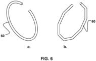
- elastic elements such as Fig.6
- the metal springs shown come into consideration, which can be designed in particular as rounded (a) or folded (b) open ring elements.
- Fig.3 shows a perspective view of the wheel quick change system from Fig.2 from behind, whereby in connection with Fig.2 the locking elements 80 can be seen, which are each arranged on the front side of the quick-release axle 30 and wheel 50 and are designed to be complementary to one another, so that the wheel 50 and quick-release axle 30 are connected to one another in a rotationally fixed manner and the torque of the quick-release axle 30 can be transmitted directly to the wheel 50.
- the locking elements 80 are arranged in particular rotationally symmetrical - in the present case there are three locking elements 80 which are each arranged offset from one another at an angle of 120°.
- Fig.4 shows a sectional view through the previously shown quick-change wheel system.
- the quick-release axle 30 has two consecutive sections of different diameters in the longitudinal direction, with the elastic element only being arranged on the section with a small diameter facing the wheel 50.
- the quick-release axle 30 and the axle mount 40 of the wheel 50 are designed to be complementary, so that the axle mount 40 of the wheel 50 can completely accommodate the front section of the quick-release axle 30, with the elastic element 60 designed as an O-ring engaging in the groove 70 provided in the axle mount 40.
- Fig.5 shows an alternative embodiment of a preferably designed quick-change wheel system.
- the quick-release axle 30, which is designed in particular as an axle adapter, has two consecutive sections of different diameters in the longitudinal direction, both sections being accommodated by the axle mount 40 of the wheel 50.
- the quick-release axle 30 has a further elastic element 60 on the other section of the quick-release axle 30, which extends at least partially around this section and beyond the circumference of this section and causes a frictional connection between the quick-release axle 30 and the wheel 50.
- the axle mount 40 of the wheel 50 is complementary to the two sections and can have a groove 70 which brings about a positive locking both for the first elastic element 60 and for the second elastic element 60.
Landscapes
- Engineering & Computer Science (AREA)
- Mechanical Engineering (AREA)
- Handcart (AREA)
- Diaphragms And Bellows (AREA)
Description
- Die Erfindung betrifft einen Fahrwagen für die Kanalrohrinspektion und/oder -sanierung mit einem Fahrwagenchassis, einer Mehrzahl von am Fahrwagenchassis angeordneten Steckachsen und jeweils einem von einer Steckachse aufgenommenen, eine Achsaufnahme aufweisenden Rad.
- Fahrwagen zur Befahrung von Rohrsystemen, insbesondere im Rahmen der Kanalrohrinspektion oder Kanalrohrsanierung, sind allgemein bekannt, z.B. aus der
DE 20 2009 003 388 U1 . Die bekannten Fahrwagen sind üblicherweise modular aufgebaut und weisen zum Befahren von Rohren unterschiedlicher Nennweiten eine an die jeweilige Nennweite des jeweiligen Rohrs angepasste Größe auf. Dabei ist es aufgrund des modularen Aufbaus - mitunter mittels nur eines einzigen Werkzeugs - möglich, einen Fahrwagen vorbestimmter Größe an den jeweiligen Einsatzzweck anzupassen, wobei die einzelnen Komponenten oftmals auch unabhängig von der Größe des Fahrwagens verwendbar sind. So lassen sich die bekannten Fahrwagen je nach Bedarf mit nur wenigen Handgriffen dem Einsatzzweck entsprechend ausrüsten und umbauen, wobei der Höhenverstellung und der Auswahl der Räder im Rahmen der rohrmittigen Befahrung eine besondere Bedeutung zukommt. - Die Dokumente
DE 102020002327 A1 undDE 202015007064 U1 zeigen weitere Fahrwagen der genannten Art. - So werden Fahrwagen regelmäßig mit einer Mehrzahl von Radsätzen ausgeliefert, die sich nicht nur hinsichtlich des Raddurchmessers, sondern auch hinsichtlich deren Eignung zum Befahren von unterschiedlich griffigen/rauen Rohrmaterialien unterscheiden.
- Um die bei der an den jeweiligen Einsatzzweck angepassten Einrichtung eines Fahrwagens anfallenden Rüst- bzw. Umrüstzeiten möglichst kurz zu halten, sind Radschnellwechselsysteme entwickelt worden, die einen einfachen und schnellen Austausch der Räder eines Fahrwagens ermöglichen sollen. Ein derartiges Schnellwechselsystem für Fahrwagenräder eines Kanalinspektions- und/oder Kanalreinigungswagens ist beispielsweise aus der
EP 2 939 848 B1 bekannt. - Der Nachteil der bekannten Schnellwechselsysteme liegt allerdings in einem komplexen Aufbau, der in einem arbeitsaufwändigen Herstellungsverfahren realisiert werden muss und einerseits aufgrund seiner Komplexität ein gewisses Verständnis bei der Handhabung des Fahrwagens erfordert und andererseits aufgrund seiner Verschleißanfälligkeit und Schmutzanfälligkeit einen hohen Wartungsaufwand begründet.
- Aufgabe der Erfindung ist es daher, ein Schnellwechselsystem für die Räder eines Fahrwagens für die Kanalrohrinspektion und/oder -sanierung zu schaffen, das einfach aufgebaut, schmutzunempfindlich, einfach und schnell handzuhaben und auch einfach zu warten ist.
- Diese Aufgabe wird erfindungsgemäß durch den Fahrwagen mit den Merkmalen von Anspruch 1 gelöst. Die Unteransprüche geben vorteilhafte Ausgestaltungen der Erfindung wieder.
- Der Erfindung liegt die Erkenntnis zugrunde, dass die Räder eines Fahrwagens aufgrund der gebogenen Form der Rohrsohle bei geeigneter Konstruktion der Fügestelle zwischen Rad und Steckachse stets auf die Steckachse gedrückt werden, sodass eine axiale Sicherung der Räder gegen eine unbeabsichtigte Demontage während des Fahrbetriebs nicht zwingend erforderlich ist. Solange nämlich außerzentrische Kräfte auf das Rad wirken, verbleibt das Rad aufgrund der selbsthemmenden Eigenschaften der Verbindung von Achse und Rad auf der Achse. Wird hingegen bei der Demontage eine zentrische Kraft aufgebracht kann das Rad demontiert werden.
- Um die Räder beim Einbringen des Fahrwagens ins Rohr, Kippen des Fahrwagens auf die Seite innerhalb des Rohrs und anderer unvorhersehbarer technischer Hindernisse gegen ein ungewolltes Verschieben auf der Steckachse zu sichern, ist ein elastisches Element vorgesehen, das einen ein Ablaufen des Rads verhindernden Kraftschluss von Steckachse und Rad bewirkt. Die Drehmomentmitnahme des auf der Steckachse angeordneten Rads erfolgt durch einen Formschluss, der beispielsweise mit als Zylinderstifte oder gefräste Kontur ausgebildeten Verriegelungselementen erzeugt werden kann.
- Erfindungsgemäß wird also ein Fahrwagen für die Kanalrohrinspektion und/oder -sanierung vorgeschlagen, der ein Fahrwagenchassis, eine Mehrzahl von am Fahrwagenchassis angeordnete Steckachsen und jeweils wenigstens ein auf einer Steckachse angeordnetes, eine Achsaufnahme aufweisendes Rad besitzt, wobei wenigstens eine Steckachse ein sich wenigstens teilweise um die Steckachse und sich über den Umfang der Steckachse hinaus erstreckendes, einen Kraftschluss von Steckachse und Rad bewirkendes elastisches Element aufweist. Als Steckachse wird vorliegend die die Drehbewegung eines Rads bewirkende Welle oder ein mit der Welle verbundener Achsadapter angesehen. Das elastische Element ist dabei insbesondere von einer am Umfang der Steckachse vorgesehenen Nut derart aufgenommen, dass das elastische Element gegen ein axiales Verschieben auf der Steckachse gesichert ist. Steckachse und Achsaufnahme sind im Wesentlichen komplementär zueinander ausgebildet. Es versteht sich, dass nicht nur eine Steckachse erfindungsgemäß ausgestaltet, sondern bevorzugt vorgesehen ist, dass alle am Fahrwagen angeordneten Steckachsen gemäß der Erfindung ausgebildet sind.
- Das elastische Element ist bevorzugt als elastisches Ringelement ausgebildet, wobei das Ringelement als ein offener Ring oder als ein geschlossener Ring ausgestaltet sein kann. Jedenfalls ist das elastische Element bevorzugt ein Elastomer oder eine Metallfeder, wobei das elastische Element im Fall eines Elastomers besonders bevorzugt ein Dichtungselement, höchst bevorzugt ein O-Ring ist. Nach einer weiteren Alternative kann das elastische Element auch aus Kunststoff gefertigt sein.
- Die Ausgestaltung als O-Ring ermöglicht eine einfache Installation und einen einfachen Austausch bei Verschleiß. Die Ausgestaltung als Metallfeder, insbesondere als elastisches Ringelement aus Edelstahl ist insbesondere bei Einsätzen unter dem Gesichtspunkt des Explosionsschutzes von Vorteil.
- Weiter ist bevorzugt vorgesehen, dass die Achsaufnahme eine das elastische Element teilweise aufnehmende, einen Formschluss von Steckachse und Rad bewirkende Nut aufweist. Die in der Achsaufnahme innenliegende Nut zur teilweisen Aufnahme des elastischen Elements sorgt nicht nur für eine zusätzliche durch die Form vermittelte Verbindung zwischen Steckachse und Rad, sondern vermittelt dem Benutzer aufgrund der haptischen Eigenschaften eine ordnungsgemäße Befestigung des Rads auf der Steckachse.
- Besonders bevorzugt ist vorgesehen, dass die Steckachse, die insbesondere als Achsadapter ausgebildet sein kann, in Längsrichtung zwei aufeinanderfolgende Abschnitte unterschiedlichen Durchmessers aufweist, wobei beide Abschnitte von der Achsaufnahme des Rads aufgenommen sind. Dabei weist die Steckachse zusätzlich zu dem vorgenannten elastischen Element, das an dem einen Abschnitt der Steckachse angeordnet ist, ein weiteres sich am anderen Abschnitt der Steckachse wenigstens teilweise um diesen Abschnitt und sich über den Umfang dieses Abschnitts hinaus erstreckendes, einen Kraftschluss von Steckachse und Rad bewirkendes elastisches Element auf. Die Achsaufnahme des Rads ist dabei komplementär zu den beiden Abschnitten ausgebildet und kann sowohl für das erste elastische Element als auch für das zweite elastische Element eine einen Formschluss bewirkende Nut aufweisen.
- Für die Drehmomentübertragung von der Steckachse auf das Rad sind an der Steckachse und dem Rad jeweils stirnseitig angeordnete, miteinander kooperierende, ein Drehen des Rads auf der Steckachse verhindernde Verriegelungselemente vorgesehen. Diese Verriegelungselemente sind besonders bevorzugt rotationssymmetrisch angeordnet.
- Schließlich ist vorgesehen, dass der Fahrwagen ein Kamerafahrwagen und/oder Sanierungsfahrwagen ist.
- Die Erfindung wird im Folgenden anhand eines in den beigefügten Zeichnungen dargestellten, besonders bevorzugt ausgestalteten Ausführungsbeispiels näher erläutert. Es zeigen:
- Fig. 1
- eine Übersicht eines besonders bevorzugt ausgestalteten Fahrwagens in einem Rohr;
- Fig. 2
- eine perspektivische Ansicht eines Radschnellwechselsystems eines besonders bevorzugt ausgestalteten Fahrwagens der Erfindung von vorn;
- Fig. 3
- eine perspektivische Ansicht des Radschnellwechselsystems aus
Fig. 2 von hinten; - Fig. 4
- eine geschnittene Ansicht durch das zuvor dargestellte Radschnellwechselsystem;
- Fig. 5
- eine alternative Ausgestaltung eines bevorzugt ausgestalteten Radschnellwechselsystems; und
- Fig. 6
- zwei besonders bevorzugte Ausführungsbeispiele von als Metallfedern ausgebildeten elastischen Elementen.
-
Fig. 1 zeigt einen in ein Rohr eingebrachten besonders bevorzugt ausgestalteten Fahrwagen für die Kanalrohrinspektion und/oder -sanierung. Der im Rohr R angeordnete Fahrwagen 10, der insbesondere als Kamerafahrwagen ausgebildet sein kann, besteht - wie bekannt - aus einem Fahrwagenchassis 20 mit einer Mehrzahl von am Fahrwagenchassis 20 angeordneten Steckachsen 30 und jeweils einem von einer Steckachse 30 aufgenommenen Rad 50. - Die erfindungsgemäßen Besonderheiten ergeben sich aus den folgenden Abbildungen, von denen
Fig. 2 eine perspektivische Ansicht eines Radschnellwechselsystems des inFig. 1 dargestellten Fahrwagens 10 von vorn zeigt. Insbesondere zeigtFig. 2 eine als Steckadapter ausgebildete Steckachse 30 und ein Rad 50, dessen Achsaufnahme 40 komplementär zur Steckachse ausgebildet ist. Es ist deutlich zu erkennen, dass die Steckachse 30 ein sich um die Steckachse 30 und sich über den Umfang der Steckachse 30 hinaus erstreckendes elastisches Element 60 in Form eines O-Rings aufweist, das einen Kraftschluss von Steckachse 30 und Rad 50 vermittelt. Der O-Ring 60 ist ein aus einem Elastomer gebildeter geschlossener Ring, der auch als Dichtungselement Verwendung findet und somit für den vorliegenden Zweck ohne weiteres verfügbar ist. Der O-Ring 60 ist in radialer Richtung teilweise von einer an der Steckachse vorgesehen Nut aufgenommen und ragt über den Umfang des vorderen Abschnitts der Steckachse 30 hinaus. Dabei ist ebenso ersichtlich, dass in der Achsaufnahme 40 des Rads 50 eine innenliegende Nut 70 vorgesehen ist, in die der O-Ring 60 beim Aufsetzen des Rads 50 auf die Steckachse 30 unter Ausbildung eines Formschlusses zwischen Steckachse 30 und Rad 50 eingesetzt werden kann. - Alternativ zu einer Verwendung von als O-Ringen ausgebildeten Elastomeren kommen als elastische Elemente die in
Fig. 6 dargestellten Metallfedern in Betracht, die insbesondere als rundgebogene (a) oder gekantete (b) offene Ringelemente ausgebildet sein können. -
Fig. 3 zeigt eine perspektivische Ansicht des Radschnellwechselsystems ausFig. 2 von hinten, wobei im Zusammenhang mitFig. 2 die Verriegelungselemente 80 erkennbar sind, die jeweils stirnseitig an Steckachse 30 und Rad 50 angeordnet und komplementär zueinander ausgebildet sind, sodass bei Rad 50 und Steckachse 30 drehfest miteinander verbunden sind und das Drehmoment der Steckachse 30 auf das Rad 50 unmittelbar übertragen werden kann. Die Verriegelungselemente 80 sind dabei insbesondere rotationssymmetrisch angeordnet - vorliegend handelt es sich um drei Verriegelungselemente 80 die jeweils in einem Winkel von 120° versetzt zueinander angeordnet sind. -
Fig. 4 zeigt eine geschnittene Ansicht durch das zuvor dargestellte Radschnellwechselsystem. In dieser Schnittansicht ist zu erkennen, dass die Steckachse 30 in Längsrichtung zwei aufeinanderfolgende Abschnitte unterschiedlichen Durchmessers aufweist, wobei das elastische Element nur an dem dem Rad 50 zugewandten Abschnitt mit geringem Durchmesser angeordnet ist. Insgesamt sind Steckachse 30 und die Achsaufnahme 40 des Rads 50 komplementär ausgebildet, sodass die Achsaufnahme 40 des Rads 50 den vorderen Abschnitt der Steckachse 30 vollständig aufnehmen kann, wobei das als O-Ring ausgebildete elastische Element 60 in die in der Achsaufnahme 40 vorgesehenen Nut 70 einrastet. -
Fig. 5 zeigt eine alternative Ausgestaltung eines bevorzugt ausgebildeten Radschnellwechselsystems. Besonders bevorzugt ist vorgesehen, dass die Steckachse 30, die insbesondere als Achsadapter ausgebildet ist, in Längsrichtung zwei aufeinanderfolgende Abschnitte unterschiedlichen Durchmessers aufweist, wobei beide Abschnitte von der Achsaufnahme 40 des Rads 50 aufgenommen sind. Dabei weist die Steckachse 30 zusätzlich zu dem vorgenannten elastischen Element 60, das an dem einen Abschnitt der Steckachse 30 angeordnet ist, ein weiteres sich am anderen Abschnitt der Steckachse 30 wenigstens teilweise um diesen Abschnitt und sich über den Umfang dieses Abschnitts hinaus erstreckendes, einen Kraftschluss von Steckachse 30 und Rad 50 bewirkendes elastisches Element 60 auf. Die Achsaufnahme 40 des Rads 50 ist dabei komplementär zu den beiden Abschnitten ausgebildet und kann sowohl für das erste elastische Element 60 als auch für das zweite elastische Element 60 eine einen Formschluss bewirkende Nut 70 aufweisen.
Claims (9)
- Fahrwagen (10) für die Kanalrohrinspektion und/oder -sanierung mit einem Fahrwagenchassis (20), einer Mehrzahl von am Fahrwagenchassis (20) angeordneten Steckachsen (30) und jeweils wenigstens einem auf einer Steckachse (30) angeordneten, eine Achsaufnahme (40) aufweisenden Rad (50),
dadurch gekennzeichnet, dass
wenigstens eine Steckachse (30) ein sich wenigstens teilweise um die Steckachse (30) und sich über den Umfang der Steckachse (30) hinaus erstreckendes, einen Kraftschluss von Steckachse (30) und Rad (50) bewirkendes elastisches Element (60) aufweist. - Fahrwagen (10) nach Anspruch 1, dadurch gekennzeichnet, dass das elastische Element (60) ein als offener Ring oder als geschlossener Ring ausgebildetes elastisches Ringelement ist.
- Fahrwagen (10) nach einem der vorhergehenden Ansprüche, dadurch gekennzeichnet, dass das elastische Element (60) ein Elastomer oder eine Metallfeder ist.
- Fahrwagen (10) nach Anspruch 3, dadurch gekennzeichnet, dass das Elastomer ein Dichtungselement ist.
- Fahrwagen (10) nach Anspruch 4, dadurch gekennzeichnet, dass das Dichtungselement ein O-Ring ist.
- Fahrwagen (10) nach einem der vorhergehenden Ansprüche, dadurch gekennzeichnet, dass die Achsaufnahme (40) eine das elastische Element (60) teilweise aufnehmende, einen Formschluss von Steckachse (30) und Rad (50) bewirkende Nut (70) aufweist.
- Fahrwagen (10) nach einem der vorhergehenden Ansprüche, dadurch gekennzeichnet, dass die Steckachse (30) und das Rad (50) jeweils mindestens ein stirnseitig angeordnetes Verriegelungselement (80) aufweisen, wobei die Verriegelungselemente von Steckachse und Rad miteinander kooperieren und damit ein Drehen des Rads auf der Steckachse verhindern.
- Fahrwagen (10) nach Anspruch 7, dadurch gekennzeichnet, dass die Verriegelungselemente (80) rotationssymmetrisch angeordnet sind.
- Fahrwagen (10) nach einem der vorhergehenden Ansprüche, dadurch gekennzeichnet, dass der Fahrwagen (10) ein Kamerafahrwagen oder Sanierungsfahrwagen ist.
Applications Claiming Priority (1)
| Application Number | Priority Date | Filing Date | Title |
|---|---|---|---|
| DE102022103165.9A DE102022103165A1 (de) | 2022-02-10 | 2022-02-10 | Fahrwagen für die Kanalrohrinspektion und/oder -sanierung |
Publications (3)
| Publication Number | Publication Date |
|---|---|
| EP4238779A1 EP4238779A1 (de) | 2023-09-06 |
| EP4238779C0 EP4238779C0 (de) | 2024-06-05 |
| EP4238779B1 true EP4238779B1 (de) | 2024-06-05 |
Family
ID=84440025
Family Applications (1)
| Application Number | Title | Priority Date | Filing Date |
|---|---|---|---|
| EP22211927.3A Active EP4238779B1 (de) | 2022-02-10 | 2022-12-07 | Fahrwagen für die kanalrohrinspektion und/oder -sanierung |
Country Status (2)
| Country | Link |
|---|---|
| EP (1) | EP4238779B1 (de) |
| DE (1) | DE102022103165A1 (de) |
Family Cites Families (7)
| Publication number | Priority date | Publication date | Assignee | Title |
|---|---|---|---|---|
| US2289448A (en) | 1941-04-25 | 1942-07-14 | Monroe Benjamin Cullen | Demountable wheel |
| DE202009003388U1 (de) | 2009-03-12 | 2009-05-14 | Ibak Helmut Hunger Gmbh & Co. Kg | Kameramodul für einen Fahrwagen zur Kanalinspektion |
| DE202013104734U1 (de) | 2013-10-21 | 2013-11-05 | Ipek International Gmbh | Schnellwechselsystem für Räder eines Inspektionswagens |
| DE202014101827U1 (de) | 2014-04-16 | 2014-05-12 | Ipek International Gmbh | Schnellwechselsystem für Räder |
| DE202015007064U1 (de) | 2015-10-13 | 2016-10-14 | Hema Metallbearbeitung Gmbh | Fahrwagen für Inspektions- oder Sanierungsarbeiten |
| EP3628507B1 (de) * | 2018-09-28 | 2023-06-07 | Gunnersbury Global Trade Limited | Diebstahlsicherungsvorrichtung für das rad eines fahrzeugs |
| DE102020002327A1 (de) * | 2020-04-16 | 2021-10-21 | Rausch Gmbh | Fahrwagen für Inspektions- und/oder Sanierungstätigkeiten in einem Kanalrohr und Schnellverschluss zum lösbaren Befestigen eines Rades an einer Achse eines solchen Fahrwagens |
-
2022
- 2022-02-10 DE DE102022103165.9A patent/DE102022103165A1/de not_active Ceased
- 2022-12-07 EP EP22211927.3A patent/EP4238779B1/de active Active
Also Published As
| Publication number | Publication date |
|---|---|
| EP4238779C0 (de) | 2024-06-05 |
| DE102022103165A1 (de) | 2023-08-10 |
| EP4238779A1 (de) | 2023-09-06 |
Similar Documents
| Publication | Publication Date | Title |
|---|---|---|
| DE102007016822A1 (de) | Gestängekupplung mit Zapfen | |
| EP2939848B1 (de) | Schnellwechselsystem für räder | |
| WO2007057172A1 (de) | Handschutzanordnung, laufanordnung und waffe | |
| EP2862637B1 (de) | Schnellwechselsystem für Räder eines Inspektionswagens | |
| EP0622557B1 (de) | Drehelastische Wellenkupplung | |
| EP4238779B1 (de) | Fahrwagen für die kanalrohrinspektion und/oder -sanierung | |
| WO2008122416A2 (de) | Gestängekupplung mit opferelement | |
| DE102015000499A1 (de) | Vortriebsroboter für Kanäle oder Leitungen | |
| DE102005001535B3 (de) | Befestigungsanordnung für einen Meißel und Demontagewerkzeug | |
| DE3928211C1 (de) | ||
| DE19913747C2 (de) | Vorrichtung zum Reinigen bzw. Säubern von langgestreckten Hohlräumen | |
| DE202015007064U1 (de) | Fahrwagen für Inspektions- oder Sanierungsarbeiten | |
| DE202017005554U1 (de) | Steckschlüssel für das Einschrauben von Gewindeelementen | |
| DE102020002327A1 (de) | Fahrwagen für Inspektions- und/oder Sanierungstätigkeiten in einem Kanalrohr und Schnellverschluss zum lösbaren Befestigen eines Rades an einer Achse eines solchen Fahrwagens | |
| DE102015106739A1 (de) | Drehstabfederachse | |
| CH717074B1 (de) | Werkzeug-Kupplung für ein werkzeugfreies Koppeln und Entkoppeln eines Hohlkernbohrers an eine Antriebseinheit. | |
| EP1095741A2 (de) | Bohr- und/oder Meisselwerkzeug | |
| DE102010037619A1 (de) | Hoch-Tiefauslegervorrichtung | |
| DE3714030A1 (de) | Reinigungsgeraet fuer feuerwaffenlaeufe und geschuetzrohre | |
| EP3244122B1 (de) | Tragvorrichtung | |
| DE102019109101A1 (de) | Werkzeugadapter für einen Drehmomentschlüssel, Montageanordnung mit dem Werkzeugadapter und dem Drehmomentschlüssel und Verfahren zur Montage einer Nutmutter mit der Montageanordnung | |
| EP0776775A1 (de) | Radlagerung | |
| DE102013107050A1 (de) | Achse für ein Nutzfahrzeug, Achsaggregat und Nutzfahrzeug mit einer derartigen Achse | |
| DE29815481U1 (de) | Einstellgerät für Federbeine | |
| DE2937655C2 (de) | Rohrförmige Fahrschiene |
Legal Events
| Date | Code | Title | Description |
|---|---|---|---|
| PUAI | Public reference made under article 153(3) epc to a published international application that has entered the european phase |
Free format text: ORIGINAL CODE: 0009012 |
|
| STAA | Information on the status of an ep patent application or granted ep patent |
Free format text: STATUS: REQUEST FOR EXAMINATION WAS MADE |
|
| 17P | Request for examination filed |
Effective date: 20230720 |
|
| AK | Designated contracting states |
Kind code of ref document: A1 Designated state(s): AL AT BE BG CH CY CZ DE DK EE ES FI FR GB GR HR HU IE IS IT LI LT LU LV MC ME MK MT NL NO PL PT RO RS SE SI SK SM TR |
|
| GRAP | Despatch of communication of intention to grant a patent |
Free format text: ORIGINAL CODE: EPIDOSNIGR1 |
|
| STAA | Information on the status of an ep patent application or granted ep patent |
Free format text: STATUS: GRANT OF PATENT IS INTENDED |
|
| GRAS | Grant fee paid |
Free format text: ORIGINAL CODE: EPIDOSNIGR3 |
|
| INTG | Intention to grant announced |
Effective date: 20240318 |
|
| GRAA | (expected) grant |
Free format text: ORIGINAL CODE: 0009210 |
|
| STAA | Information on the status of an ep patent application or granted ep patent |
Free format text: STATUS: THE PATENT HAS BEEN GRANTED |
|
| AK | Designated contracting states |
Kind code of ref document: B1 Designated state(s): AL AT BE BG CH CY CZ DE DK EE ES FI FR GB GR HR HU IE IS IT LI LT LU LV MC ME MK MT NL NO PL PT RO RS SE SI SK SM TR |
|
| REG | Reference to a national code |
Ref country code: CH Ref legal event code: EP |
|
| REG | Reference to a national code |
Ref country code: DE Ref legal event code: R096 Ref document number: 502022000994 Country of ref document: DE |
|
| REG | Reference to a national code |
Ref country code: IE Ref legal event code: FG4D Free format text: LANGUAGE OF EP DOCUMENT: GERMAN |
|
| U01 | Request for unitary effect filed |
Effective date: 20240605 |
|
| U07 | Unitary effect registered |
Designated state(s): AT BE BG DE DK EE FI FR IT LT LU LV MT NL PT SE SI Effective date: 20240620 |
|
| PG25 | Lapsed in a contracting state [announced via postgrant information from national office to epo] |
Ref country code: HR Free format text: LAPSE BECAUSE OF FAILURE TO SUBMIT A TRANSLATION OF THE DESCRIPTION OR TO PAY THE FEE WITHIN THE PRESCRIBED TIME-LIMIT Effective date: 20240605 |
|
| PG25 | Lapsed in a contracting state [announced via postgrant information from national office to epo] |
Ref country code: GR Free format text: LAPSE BECAUSE OF FAILURE TO SUBMIT A TRANSLATION OF THE DESCRIPTION OR TO PAY THE FEE WITHIN THE PRESCRIBED TIME-LIMIT Effective date: 20240906 |
|
| PG25 | Lapsed in a contracting state [announced via postgrant information from national office to epo] |
Ref country code: ES Free format text: LAPSE BECAUSE OF FAILURE TO SUBMIT A TRANSLATION OF THE DESCRIPTION OR TO PAY THE FEE WITHIN THE PRESCRIBED TIME-LIMIT Effective date: 20240605 |
|
| PG25 | Lapsed in a contracting state [announced via postgrant information from national office to epo] |
Ref country code: NO Free format text: LAPSE BECAUSE OF FAILURE TO SUBMIT A TRANSLATION OF THE DESCRIPTION OR TO PAY THE FEE WITHIN THE PRESCRIBED TIME-LIMIT Effective date: 20240905 Ref country code: HR Free format text: LAPSE BECAUSE OF FAILURE TO SUBMIT A TRANSLATION OF THE DESCRIPTION OR TO PAY THE FEE WITHIN THE PRESCRIBED TIME-LIMIT Effective date: 20240605 Ref country code: GR Free format text: LAPSE BECAUSE OF FAILURE TO SUBMIT A TRANSLATION OF THE DESCRIPTION OR TO PAY THE FEE WITHIN THE PRESCRIBED TIME-LIMIT Effective date: 20240906 Ref country code: ES Free format text: LAPSE BECAUSE OF FAILURE TO SUBMIT A TRANSLATION OF THE DESCRIPTION OR TO PAY THE FEE WITHIN THE PRESCRIBED TIME-LIMIT Effective date: 20240605 Ref country code: RS Free format text: LAPSE BECAUSE OF FAILURE TO SUBMIT A TRANSLATION OF THE DESCRIPTION OR TO PAY THE FEE WITHIN THE PRESCRIBED TIME-LIMIT Effective date: 20240905 |
|
| U20 | Renewal fee for the european patent with unitary effect paid |
Year of fee payment: 3 Effective date: 20241029 |
|
| PG25 | Lapsed in a contracting state [announced via postgrant information from national office to epo] |
Ref country code: PL Free format text: LAPSE BECAUSE OF FAILURE TO SUBMIT A TRANSLATION OF THE DESCRIPTION OR TO PAY THE FEE WITHIN THE PRESCRIBED TIME-LIMIT Effective date: 20240605 |
|
| PG25 | Lapsed in a contracting state [announced via postgrant information from national office to epo] |
Ref country code: IS Free format text: LAPSE BECAUSE OF FAILURE TO SUBMIT A TRANSLATION OF THE DESCRIPTION OR TO PAY THE FEE WITHIN THE PRESCRIBED TIME-LIMIT Effective date: 20241005 |
|
| PG25 | Lapsed in a contracting state [announced via postgrant information from national office to epo] |
Ref country code: CZ Free format text: LAPSE BECAUSE OF FAILURE TO SUBMIT A TRANSLATION OF THE DESCRIPTION OR TO PAY THE FEE WITHIN THE PRESCRIBED TIME-LIMIT Effective date: 20240605 |
|
| PG25 | Lapsed in a contracting state [announced via postgrant information from national office to epo] |
Ref country code: RO Free format text: LAPSE BECAUSE OF FAILURE TO SUBMIT A TRANSLATION OF THE DESCRIPTION OR TO PAY THE FEE WITHIN THE PRESCRIBED TIME-LIMIT Effective date: 20240605 Ref country code: SK Free format text: LAPSE BECAUSE OF FAILURE TO SUBMIT A TRANSLATION OF THE DESCRIPTION OR TO PAY THE FEE WITHIN THE PRESCRIBED TIME-LIMIT Effective date: 20240605 |
|
| PG25 | Lapsed in a contracting state [announced via postgrant information from national office to epo] |
Ref country code: SM Free format text: LAPSE BECAUSE OF FAILURE TO SUBMIT A TRANSLATION OF THE DESCRIPTION OR TO PAY THE FEE WITHIN THE PRESCRIBED TIME-LIMIT Effective date: 20240605 |
|
| PG25 | Lapsed in a contracting state [announced via postgrant information from national office to epo] |
Ref country code: SM Free format text: LAPSE BECAUSE OF FAILURE TO SUBMIT A TRANSLATION OF THE DESCRIPTION OR TO PAY THE FEE WITHIN THE PRESCRIBED TIME-LIMIT Effective date: 20240605 Ref country code: SK Free format text: LAPSE BECAUSE OF FAILURE TO SUBMIT A TRANSLATION OF THE DESCRIPTION OR TO PAY THE FEE WITHIN THE PRESCRIBED TIME-LIMIT Effective date: 20240605 Ref country code: RO Free format text: LAPSE BECAUSE OF FAILURE TO SUBMIT A TRANSLATION OF THE DESCRIPTION OR TO PAY THE FEE WITHIN THE PRESCRIBED TIME-LIMIT Effective date: 20240605 Ref country code: PL Free format text: LAPSE BECAUSE OF FAILURE TO SUBMIT A TRANSLATION OF THE DESCRIPTION OR TO PAY THE FEE WITHIN THE PRESCRIBED TIME-LIMIT Effective date: 20240605 Ref country code: IS Free format text: LAPSE BECAUSE OF FAILURE TO SUBMIT A TRANSLATION OF THE DESCRIPTION OR TO PAY THE FEE WITHIN THE PRESCRIBED TIME-LIMIT Effective date: 20241005 Ref country code: CZ Free format text: LAPSE BECAUSE OF FAILURE TO SUBMIT A TRANSLATION OF THE DESCRIPTION OR TO PAY THE FEE WITHIN THE PRESCRIBED TIME-LIMIT Effective date: 20240605 |
|
| PLBE | No opposition filed within time limit |
Free format text: ORIGINAL CODE: 0009261 |
|
| STAA | Information on the status of an ep patent application or granted ep patent |
Free format text: STATUS: NO OPPOSITION FILED WITHIN TIME LIMIT |
|
| 26N | No opposition filed |
Effective date: 20250306 |
|
| PG25 | Lapsed in a contracting state [announced via postgrant information from national office to epo] |
Ref country code: MC Free format text: LAPSE BECAUSE OF FAILURE TO SUBMIT A TRANSLATION OF THE DESCRIPTION OR TO PAY THE FEE WITHIN THE PRESCRIBED TIME-LIMIT Effective date: 20240605 |
|
| PG25 | Lapsed in a contracting state [announced via postgrant information from national office to epo] |
Ref country code: IE Free format text: LAPSE BECAUSE OF NON-PAYMENT OF DUE FEES Effective date: 20241207 |
|
| U20 | Renewal fee for the european patent with unitary effect paid |
Year of fee payment: 4 Effective date: 20251020 |