EP4238544B1 - Stehrahmen und kniestütze für einen stehrahmen - Google Patents
Stehrahmen und kniestütze für einen stehrahmen Download PDFInfo
- Publication number
- EP4238544B1 EP4238544B1 EP23153124.5A EP23153124A EP4238544B1 EP 4238544 B1 EP4238544 B1 EP 4238544B1 EP 23153124 A EP23153124 A EP 23153124A EP 4238544 B1 EP4238544 B1 EP 4238544B1
- Authority
- EP
- European Patent Office
- Prior art keywords
- knee
- axis
- relative
- bracket
- standing frame
- Prior art date
- Legal status (The legal status is an assumption and is not a legal conclusion. Google has not performed a legal analysis and makes no representation as to the accuracy of the status listed.)
- Active
Links
Images

Classifications
-
- A—HUMAN NECESSITIES
- A61—MEDICAL OR VETERINARY SCIENCE; HYGIENE
- A61G—TRANSPORT, PERSONAL CONVEYANCES, OR ACCOMMODATION SPECIALLY ADAPTED FOR PATIENTS OR DISABLED PERSONS; OPERATING TABLES OR CHAIRS; CHAIRS FOR DENTISTRY; FUNERAL DEVICES
- A61G7/00—Beds specially adapted for nursing; Devices for lifting patients or disabled persons
- A61G7/10—Devices for lifting patients or disabled persons, e.g. special adaptations of hoists thereto
- A61G7/1073—Parts, details or accessories
- A61G7/1082—Rests specially adapted for
- A61G7/1096—Knee, upper or lower leg
-
- A—HUMAN NECESSITIES
- A61—MEDICAL OR VETERINARY SCIENCE; HYGIENE
- A61G—TRANSPORT, PERSONAL CONVEYANCES, OR ACCOMMODATION SPECIALLY ADAPTED FOR PATIENTS OR DISABLED PERSONS; OPERATING TABLES OR CHAIRS; CHAIRS FOR DENTISTRY; FUNERAL DEVICES
- A61G5/00—Chairs or personal conveyances specially adapted for patients or disabled persons, e.g. wheelchairs
- A61G5/10—Parts, details or accessories
- A61G5/14—Standing-up or sitting-down aids
-
- A—HUMAN NECESSITIES
- A61—MEDICAL OR VETERINARY SCIENCE; HYGIENE
- A61G—TRANSPORT, PERSONAL CONVEYANCES, OR ACCOMMODATION SPECIALLY ADAPTED FOR PATIENTS OR DISABLED PERSONS; OPERATING TABLES OR CHAIRS; CHAIRS FOR DENTISTRY; FUNERAL DEVICES
- A61G5/00—Chairs or personal conveyances specially adapted for patients or disabled persons, e.g. wheelchairs
- A61G5/10—Parts, details or accessories
-
- A—HUMAN NECESSITIES
- A63—SPORTS; GAMES; AMUSEMENTS
- A63B—APPARATUS FOR PHYSICAL TRAINING, GYMNASTICS, SWIMMING, CLIMBING, OR FENCING; BALL GAMES; TRAINING EQUIPMENT
- A63B23/00—Exercising apparatus specially adapted for particular parts of the body
- A63B23/035—Exercising apparatus specially adapted for particular parts of the body for limbs, i.e. upper or lower limbs, e.g. simultaneously
- A63B23/04—Exercising apparatus specially adapted for particular parts of the body for limbs, i.e. upper or lower limbs, e.g. simultaneously for lower limbs
-
- A—HUMAN NECESSITIES
- A61—MEDICAL OR VETERINARY SCIENCE; HYGIENE
- A61G—TRANSPORT, PERSONAL CONVEYANCES, OR ACCOMMODATION SPECIALLY ADAPTED FOR PATIENTS OR DISABLED PERSONS; OPERATING TABLES OR CHAIRS; CHAIRS FOR DENTISTRY; FUNERAL DEVICES
- A61G7/00—Beds specially adapted for nursing; Devices for lifting patients or disabled persons
- A61G7/10—Devices for lifting patients or disabled persons, e.g. special adaptations of hoists thereto
- A61G7/1001—Devices for lifting patients or disabled persons, e.g. special adaptations of hoists thereto specially adapted for specific applications
Definitions
- the show invention relates to standing frames, in particular to a knee support for a standing frame.
- a standing frame (also called a stander) is a device that facilitates transitioning a disabled person from a horizontal position to a vertical position and vice versa and maintaining a disabled person in an upright position.
- Standing frames have knee supports for stabilising a knee joint when the patient is in the standing position.
- Typical knee supports have a single knee pad, configured to be positioned under the knee.
- the typical knee support can cause dislocation of the knee joint.
- the object of the invention is a knee support for a standing frame, the knee support comprising a supporting plate for attaching the knee support to the standing frame; a first knee pad rotatably attached to a first L-shaped bracket on its shorter arm; a second knee pad rotatably attached to a second L-shaped bracket on its shorter arm; wherein the longer arm of the first bracket is pivotably attached to the supporting plate near the first end thereof by means of a first holder, and the longer arm of the second bracket is pivotably attached to the supporting plate near its second end by means of a second holder, so that the first knee pad is located above the second knee pad.
- the knee support with two knee pads allows to protect and achieve straightening of the hip and knee joint.
- the double knee pad can be used for both front-supported and rear-supported verticalization.
- the double knee pad can be mounted from the front in a position above and below the knee.
- for rear-supported verticalization it supports the back of the leg.
- Use of a double knee pad improves the quality of standing and eventually preparation for walking for patients subject to hip joint and knee joint surgery, with contractures in the hip and knee joints.
- the knee pad can be adjusted in the coronal plane, to facilitate protection of limbs from excess varus deformity or valgus deformity.
- the first knee pad is pivotably attached relative to the axis, perpendicular to the axis, by means of a first slidable and pivotable coupling
- the second knee pad is pivotably attached relative to the axis, perpendicular to the axis, by means of a second slidable and pivotable coupling.
- the first slidable and pivotable coupling comprises a first body which is rotatably attached relative to the axis on the shorter arm of the first bracket, and comprises a first U-shaped rail attached to the first body rotatably relative to the axis, perpendicular to the axes and, and slidably relative to the axis
- the second slidable and pivotable coupling comprises a second body, which is rotatably attached relative to the axis on the shorter arm of the second bracket, and comprises a second U-shaped rail attached to the second body rotatably relative to the axis, perpendicular to the axes and, and slidably relative to the axis.
- the possibility to adjust the setting of the angle of the knee pads relative to the axes Y1, Y2 depending on the shape of the leg allows arranging the knee pads in a position wherein the knee pads better support the leg asides. They provide support perpendicularly to the direction of the force.
- the invention also relates to a standing frame comprising knee supports as described herein.
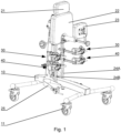
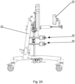
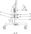
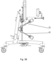
- Figs. 1 , 2A-2B , and 3A-3B show an example embodiment of a standing frame with knee supports according to an embodiment of the invention.
- the standing frame has a base 10 with a vertical column 20, to which there are attached supports for keeping a person in an upright position.
- a chest support 21 is attached to the column 20 in its upper part; below are attached a hip support 22, (opposite which there is a back support 23) and knee supports with knee pads 30, 40.
- the column 20 has footrests 25.
- the base 10 has wheels 11 that enable movement of the standing frame.
- the structure of the standing frame presented herein is merely an example; the knee support according to the invention can also be used with other types of standing frames with features similar to the embodiment presented herein.
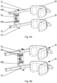
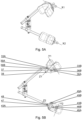
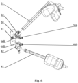
- the knee support is shown by means of a detailed example embodiment in Figs. 4A-4B , 5A-5B and 6 .
- the knee support is attached to the standing frame by means of a supporting plate 50, which in its central part has an opening with a fixing bolt 51, which enables attaching the knee support to a leg guide 24A, 24B on the standing frame.
- the knee support comprises a first knee pad 30 rotatably attached to a first L-shaped bracket 31 on its shorter arm, and a second knee pad 40 rotatably attached to a second L-shaped bracket 41 on its shorter arm.
- the longer arm of the first bracket 31 is pivotably attached to the supporting plate 50 at its first end by means of a first holder 32, while the longer arm of the second bracket 41 is pivotably attached to the supporting plate 50 at its second end by means of a second holder 42 and therefore the first knee pad 30 is located above the second knee pad 40.
- the knee pad 30, 40 has a form of a U-shaped cushion, which during use partially surrounds a part of the leg, immobilising it substantially in three directions along a segment of the leg.
- the first knee pad 30 is rotatable around the axis X1 of the shorter arm of the first bracket 31, and the second knee pad 40 is rotatable around the axis X2 of the shorter arm of the second bracket 41.
- the shorter arms of the brackets 31, 41 have a circular cross-section, thus enabling the attachment of the knee pads 30, 40, for example by means of bushings 37, 47 rotating directly on the shorter arms of the brackets 31, 41.
- the ability of the knee pads to rotate is blocked by tightening locking bolts 38, 48 that pass through openings in the bushings 37, 47.
- the first holder 32 is attached to the supporting plate 50 by means of bolts 34A which pass through an arcuate opening 34B (an opening in the form of a sector of a circle) located in the first holder 32.
- the bolts 34A In order to set the angle of inclination of the first knee pad 30, it is necessary to loosen the bolts 34A and rotate the first bracket 31 along with the first holder 32 along the opening 34B. Then, the bolts 34A can move along the opening 34B. Upon arranging the first knee pad 30 in the desired position, the bolts 34A have to be tightened.
- the second holder 42 is attached to the supporting plate 50 by means of bolts 44A which pass through an arcuate opening 44B located in the second holder 42.
- the first bracket 31 is attached to the first holder 32 in a slidable manner, thus enabling adjustment of the distance of the first knee pad 30 from the leg by changing the scope of extension of the first bracket 31 from the first holder 32.
- the ability to extend the first bracket 31 is blocked by tightening a fixing bolt 35.
- the second bracket 41 is attached to the second holder 42 in a slidable manner, thus enabling adjustment of the distance of the second knee pad 40 from the user's leg by changing the scope of extension of the second bracket 41 from the second holder 42, regardless of the position of the first knee pad 40.
- the ability to extend the second bracket 41 is blocked by tightening a fixing bolt 45.
- the first knee pad 30 is pivotable relative to the axis Y1, perpendicular to the axis X1, by means of a first slidable and pivotable coupling 33.
- the second knee pad 40 is pivotable relative to the axis Y2, perpendicular to the axis X2, by means of a second slidable and pivotable coupling 43.
- the first knee pad 30 located higher can be arranged above the knee, due to which stabilisation and stretching take place along a short segment and involve one joint only, while the second knee pad 40 located lower than the first knee pad 30 supports the shin, providing the possibility of straightening the knee joint, stretching and protection from hyperextension.
- the first pivotable coupling 33 comprises a first body 33A, which is rotatably attached relative to the axis X1 on the shorter arm of the first bracket 31, as well as a first U-shaped rail 33B attached to the first body 33A rotatably relative to the axis Z1, perpendicular to the axes X1 and Y1, and slidably relative to the axis Y1.
- the second pivotable coupling 43 comprises a second body 43A, which is rotatably attached relative to the axis X2 on the shorter arm of the second bracket 41, as well as a second U-shaped rail 43B attached to the second body 43A rotatably relative to the axis Z2, perpendicular to the axes X2 and Y2, and slidably relative to the axis Y2.
- the first body 33A may comprise a bushing 37, and the second body 43A may comprise a bushing 47.
- first knee pad 30 In order to set the angle of rotation of the first knee pad 30 relative to the axis Y1, it is necessary to loosen the bolts 36A and rotate the first knee pad 30 to the desired position. The bolts 36A then move along an elongated opening 36B in the first U-shaped rail 33B. Upon arranging the first knee pad 30 in the desired position relative to the axis Y1, it is necessary to tighten the bolts 36A. The elongated opening 36B extends along the length of the first U-shaped rail 33B.
Landscapes
- Health & Medical Sciences (AREA)
- General Health & Medical Sciences (AREA)
- Life Sciences & Earth Sciences (AREA)
- Animal Behavior & Ethology (AREA)
- Public Health (AREA)
- Veterinary Medicine (AREA)
- Orthopedic Medicine & Surgery (AREA)
- Physical Education & Sports Medicine (AREA)
- Nursing (AREA)
- Orthopedics, Nursing, And Contraception (AREA)
Claims (4)
- Kniestütze für einen Stehrahmen, wobei die Kniestütze eine Stützplatte (50) zum Anbringen der Kniestütze an dem Stehrahmen; ein erstes Kniepolster (30), das an seinem kürzeren Arm drehbar an einer ersten L-förmigen Halterung (31) angebracht ist; ein zweites Kniepolster (40), das an seinem kürzeren Arm drehbar an einer zweiten L-förmigen Halterung (41) angebracht ist; wobei der längere Arm der ersten Halterung (31) mittels eines ersten Halters (32) schwenkbar an der Stützplatte (50) nahe dem ersten Ende davon angebracht ist und der längere Arm der zweiten Halterung (41) mittels eines zweiten Halters (42) schwenkbar an der Stützplatte (50) nahe ihrem zweiten Ende angebracht ist, sodass sich das erste Kniepolster (30) über dem zweiten Kniepolster (40) befindet, umfasst.
- Kniestütze nach Anspruch 1, wobei das erste Kniepolster (30) mittels einer ersten verschiebbaren und schwenkbaren Kopplung (33) schwenkbar relativ zu einer ersten Achse (Y1), senkrecht zu einer zweiten Achse (X1), angebracht ist und das zweite Kniepolster (40) mittels einer zweiten verschiebbaren und schwenkbaren Kopplung (43) schwenkbar relativ zu einer dritten Achse (Y2), senkrecht zu einer vierten Achse (X2), angebracht ist.
- Kniestütze nach Anspruch 2, wobei die erste verschiebbare und schwenkbare Kopplung (33) einen ersten Körper (33A) umfasst, der drehbar relativ zu der zweiten Achse (X1) an dem kürzeren Arm der ersten Halterung (31) angebracht ist, und eine erste U-förmige Schiene (33B) umfasst, die an dem ersten Körper (33A) drehbar relativ zu einer fünften Achse (Z1), senkrecht zu der zweiten und der ersten Achse (X1) und (Y1), und verschiebbar relativ zu der ersten Achse (Y1) angebracht ist, und
wobei die zweite verschiebbare und schwenkbare Kopplung (43) einen zweiten Körper (43A) umfasst, der relativ zu der vierten Achse (X2) drehbar an dem kürzeren Arm der zweiten Halterung (41) angebracht ist, und eine zweite U-förmige Schiene (43B) umfasst, die an dem zweiten Körper (43A) drehbar relativ zu einer sechsten Achse (Z2), senkrecht zu der vierten und der dritten Achse (X2) und (Y2), und verschiebbar relativ zu der dritten Achse (Y2) angebracht ist. - Stehrahmen, der Kniestützen nach einem der vorhergehenden Ansprüche umfasst.
Applications Claiming Priority (1)
| Application Number | Priority Date | Filing Date | Title |
|---|---|---|---|
| PL440529A PL245428B1 (pl) | 2022-03-03 | 2022-03-03 | Wspornik kolanowy do pionizatora |
Publications (2)
| Publication Number | Publication Date |
|---|---|
| EP4238544A1 EP4238544A1 (de) | 2023-09-06 |
| EP4238544B1 true EP4238544B1 (de) | 2024-12-18 |
Family
ID=85076499
Family Applications (1)
| Application Number | Title | Priority Date | Filing Date |
|---|---|---|---|
| EP23153124.5A Active EP4238544B1 (de) | 2022-03-03 | 2023-01-24 | Stehrahmen und kniestütze für einen stehrahmen |
Country Status (2)
| Country | Link |
|---|---|
| EP (1) | EP4238544B1 (de) |
| PL (1) | PL245428B1 (de) |
Family Cites Families (3)
| Publication number | Priority date | Publication date | Assignee | Title |
|---|---|---|---|---|
| US4968050A (en) * | 1988-10-11 | 1990-11-06 | Luconex, Inc. | Mobile prone stander having adjustable axis of inclination |
| US5829766A (en) * | 1992-11-14 | 1998-11-03 | Irmgard Gohlert | Device for dressing and undressing and for the cleaning and care of the body of a handicapped person |
| DE9405539U1 (de) * | 1993-10-07 | 1994-05-26 | Meyer, Markus, 21379 Rullstorf | Kombinierte Steh- und Gehhilfe |
-
2022
- 2022-03-03 PL PL440529A patent/PL245428B1/pl unknown
-
2023
- 2023-01-24 EP EP23153124.5A patent/EP4238544B1/de active Active
Also Published As
| Publication number | Publication date |
|---|---|
| PL440529A1 (pl) | 2023-09-04 |
| EP4238544A1 (de) | 2023-09-06 |
| PL245428B1 (pl) | 2024-07-29 |
Similar Documents
| Publication | Publication Date | Title |
|---|---|---|
| US12364445B2 (en) | Patient positioning apparatus | |
| JP3330381B2 (ja) | 動的ひじ支持体 | |
| EP0454186B1 (de) | Gelenkverbindung für orthopädische Kniestütze | |
| US4620697A (en) | Surgical headrest | |
| JP5582198B2 (ja) | 頭蓋骨を安定させる小児用ヘッドレストおよびその利用法 | |
| US12059382B2 (en) | Knee joint stimulation device | |
| US20190053970A1 (en) | Multi-function adaptable lift system | |
| JP2511447B2 (ja) | 整形装置 | |
| JP2003526470A (ja) | 回内/回外・屈曲両用治療運動装置 | |
| US20120240938A1 (en) | Methods and systems for performing hip joint distraction | |
| US8894596B2 (en) | Systems, devices, and methods for mechanically reducing and fixing bone fractures | |
| WO2009062545A1 (en) | Modular device for positioning and immobilisation of a patient's body for surgical operations and corresponding operating table | |
| WO2010134937A1 (en) | Knee orthosis with hinged shin and thigh cuff | |
| US6254559B1 (en) | Adjustable hip joint assembly | |
| US20250241779A1 (en) | Brace device | |
| EP4238544B1 (de) | Stehrahmen und kniestütze für einen stehrahmen | |
| JPS5841060B2 (ja) | 手術台 | |
| EP4215171B1 (de) | Stehrahmen und rückenstütze für einen stehrahmen | |
| US20200188213A1 (en) | Spinal Cord and Meninges Stretching Frame and Method to Prevent and Treat the Root Cause of Scoliosis | |
| AU4959800A (en) | Improvements to leg supports | |
| CN110200731B (zh) | 一种婴幼儿下肢矫正工具 | |
| CN217286229U (zh) | 一种可拆卸解剖型上肢外支撑支具 | |
| CN223504345U (zh) | 一种肱骨髁上骨折闭合复位手术用体位固定支架 | |
| CN119606617A (zh) | 一种肢体固定矫形器 | |
| JPS58116359A (ja) | 手術台 |
Legal Events
| Date | Code | Title | Description |
|---|---|---|---|
| PUAI | Public reference made under article 153(3) epc to a published international application that has entered the european phase |
Free format text: ORIGINAL CODE: 0009012 |
|
| STAA | Information on the status of an ep patent application or granted ep patent |
Free format text: STATUS: THE APPLICATION HAS BEEN PUBLISHED |
|
| AK | Designated contracting states |
Kind code of ref document: A1 Designated state(s): AL AT BE BG CH CY CZ DE DK EE ES FI FR GB GR HR HU IE IS IT LI LT LU LV MC ME MK MT NL NO PL PT RO RS SE SI SK SM TR |
|
| STAA | Information on the status of an ep patent application or granted ep patent |
Free format text: STATUS: REQUEST FOR EXAMINATION WAS MADE |
|
| 17P | Request for examination filed |
Effective date: 20240305 |
|
| RBV | Designated contracting states (corrected) |
Designated state(s): AL AT BE BG CH CY CZ DE DK EE ES FI FR GB GR HR HU IE IS IT LI LT LU LV MC ME MK MT NL NO PL PT RO RS SE SI SK SM TR |
|
| GRAP | Despatch of communication of intention to grant a patent |
Free format text: ORIGINAL CODE: EPIDOSNIGR1 |
|
| STAA | Information on the status of an ep patent application or granted ep patent |
Free format text: STATUS: GRANT OF PATENT IS INTENDED |
|
| RIC1 | Information provided on ipc code assigned before grant |
Ipc: A61G 7/10 20060101AFI20240704BHEP |
|
| INTG | Intention to grant announced |
Effective date: 20240715 |
|
| GRAS | Grant fee paid |
Free format text: ORIGINAL CODE: EPIDOSNIGR3 |
|
| GRAA | (expected) grant |
Free format text: ORIGINAL CODE: 0009210 |
|
| STAA | Information on the status of an ep patent application or granted ep patent |
Free format text: STATUS: THE PATENT HAS BEEN GRANTED |
|
| AK | Designated contracting states |
Kind code of ref document: B1 Designated state(s): AL AT BE BG CH CY CZ DE DK EE ES FI FR GB GR HR HU IE IS IT LI LT LU LV MC ME MK MT NL NO PL PT RO RS SE SI SK SM TR |
|
| REG | Reference to a national code |
Ref country code: CH Ref legal event code: EP |
|
| REG | Reference to a national code |
Ref country code: DE Ref legal event code: R096 Ref document number: 602023001347 Country of ref document: DE |
|
| REG | Reference to a national code |
Ref country code: IE Ref legal event code: FG4D |
|
| REG | Reference to a national code |
Ref country code: LT Ref legal event code: MG9D |
|
| PG25 | Lapsed in a contracting state [announced via postgrant information from national office to epo] |
Ref country code: HR Free format text: LAPSE BECAUSE OF FAILURE TO SUBMIT A TRANSLATION OF THE DESCRIPTION OR TO PAY THE FEE WITHIN THE PRESCRIBED TIME-LIMIT Effective date: 20241218 |
|
| PG25 | Lapsed in a contracting state [announced via postgrant information from national office to epo] |
Ref country code: FI Free format text: LAPSE BECAUSE OF FAILURE TO SUBMIT A TRANSLATION OF THE DESCRIPTION OR TO PAY THE FEE WITHIN THE PRESCRIBED TIME-LIMIT Effective date: 20241218 |
|
| PG25 | Lapsed in a contracting state [announced via postgrant information from national office to epo] |
Ref country code: BG Free format text: LAPSE BECAUSE OF FAILURE TO SUBMIT A TRANSLATION OF THE DESCRIPTION OR TO PAY THE FEE WITHIN THE PRESCRIBED TIME-LIMIT Effective date: 20241218 |
|
| PG25 | Lapsed in a contracting state [announced via postgrant information from national office to epo] |
Ref country code: NO Free format text: LAPSE BECAUSE OF FAILURE TO SUBMIT A TRANSLATION OF THE DESCRIPTION OR TO PAY THE FEE WITHIN THE PRESCRIBED TIME-LIMIT Effective date: 20250318 |
|
| REG | Reference to a national code |
Ref country code: NL Ref legal event code: MP Effective date: 20241218 |
|
| PG25 | Lapsed in a contracting state [announced via postgrant information from national office to epo] |
Ref country code: LV Free format text: LAPSE BECAUSE OF FAILURE TO SUBMIT A TRANSLATION OF THE DESCRIPTION OR TO PAY THE FEE WITHIN THE PRESCRIBED TIME-LIMIT Effective date: 20241218 Ref country code: GR Free format text: LAPSE BECAUSE OF FAILURE TO SUBMIT A TRANSLATION OF THE DESCRIPTION OR TO PAY THE FEE WITHIN THE PRESCRIBED TIME-LIMIT Effective date: 20250319 |
|
| PG25 | Lapsed in a contracting state [announced via postgrant information from national office to epo] |
Ref country code: RS Free format text: LAPSE BECAUSE OF FAILURE TO SUBMIT A TRANSLATION OF THE DESCRIPTION OR TO PAY THE FEE WITHIN THE PRESCRIBED TIME-LIMIT Effective date: 20250318 |
|
| PG25 | Lapsed in a contracting state [announced via postgrant information from national office to epo] |
Ref country code: NL Free format text: LAPSE BECAUSE OF FAILURE TO SUBMIT A TRANSLATION OF THE DESCRIPTION OR TO PAY THE FEE WITHIN THE PRESCRIBED TIME-LIMIT Effective date: 20241218 |
|
| REG | Reference to a national code |
Ref country code: AT Ref legal event code: MK05 Ref document number: 1751658 Country of ref document: AT Kind code of ref document: T Effective date: 20241218 |
|
| PG25 | Lapsed in a contracting state [announced via postgrant information from national office to epo] |
Ref country code: SM Free format text: LAPSE BECAUSE OF FAILURE TO SUBMIT A TRANSLATION OF THE DESCRIPTION OR TO PAY THE FEE WITHIN THE PRESCRIBED TIME-LIMIT Effective date: 20241218 |
|
| PG25 | Lapsed in a contracting state [announced via postgrant information from national office to epo] |
Ref country code: PL Free format text: LAPSE BECAUSE OF FAILURE TO SUBMIT A TRANSLATION OF THE DESCRIPTION OR TO PAY THE FEE WITHIN THE PRESCRIBED TIME-LIMIT Effective date: 20241218 |
|
| PG25 | Lapsed in a contracting state [announced via postgrant information from national office to epo] |
Ref country code: ES Free format text: LAPSE BECAUSE OF FAILURE TO SUBMIT A TRANSLATION OF THE DESCRIPTION OR TO PAY THE FEE WITHIN THE PRESCRIBED TIME-LIMIT Effective date: 20241218 |
|
| PG25 | Lapsed in a contracting state [announced via postgrant information from national office to epo] |
Ref country code: IS Free format text: LAPSE BECAUSE OF FAILURE TO SUBMIT A TRANSLATION OF THE DESCRIPTION OR TO PAY THE FEE WITHIN THE PRESCRIBED TIME-LIMIT Effective date: 20250418 |
|
| PG25 | Lapsed in a contracting state [announced via postgrant information from national office to epo] |
Ref country code: PT Free format text: LAPSE BECAUSE OF FAILURE TO SUBMIT A TRANSLATION OF THE DESCRIPTION OR TO PAY THE FEE WITHIN THE PRESCRIBED TIME-LIMIT Effective date: 20250421 |
|
| PG25 | Lapsed in a contracting state [announced via postgrant information from national office to epo] |
Ref country code: EE Free format text: LAPSE BECAUSE OF FAILURE TO SUBMIT A TRANSLATION OF THE DESCRIPTION OR TO PAY THE FEE WITHIN THE PRESCRIBED TIME-LIMIT Effective date: 20241218 |
|
| PG25 | Lapsed in a contracting state [announced via postgrant information from national office to epo] |
Ref country code: AT Free format text: LAPSE BECAUSE OF FAILURE TO SUBMIT A TRANSLATION OF THE DESCRIPTION OR TO PAY THE FEE WITHIN THE PRESCRIBED TIME-LIMIT Effective date: 20241218 Ref country code: RO Free format text: LAPSE BECAUSE OF FAILURE TO SUBMIT A TRANSLATION OF THE DESCRIPTION OR TO PAY THE FEE WITHIN THE PRESCRIBED TIME-LIMIT Effective date: 20241218 |
|
| PG25 | Lapsed in a contracting state [announced via postgrant information from national office to epo] |
Ref country code: SK Free format text: LAPSE BECAUSE OF FAILURE TO SUBMIT A TRANSLATION OF THE DESCRIPTION OR TO PAY THE FEE WITHIN THE PRESCRIBED TIME-LIMIT Effective date: 20241218 |
|
| PG25 | Lapsed in a contracting state [announced via postgrant information from national office to epo] |
Ref country code: CZ Free format text: LAPSE BECAUSE OF FAILURE TO SUBMIT A TRANSLATION OF THE DESCRIPTION OR TO PAY THE FEE WITHIN THE PRESCRIBED TIME-LIMIT Effective date: 20241218 |
|
| PG25 | Lapsed in a contracting state [announced via postgrant information from national office to epo] |
Ref country code: IT Free format text: LAPSE BECAUSE OF FAILURE TO SUBMIT A TRANSLATION OF THE DESCRIPTION OR TO PAY THE FEE WITHIN THE PRESCRIBED TIME-LIMIT Effective date: 20241218 |
|
| REG | Reference to a national code |
Ref country code: DE Ref legal event code: R119 Ref document number: 602023001347 Country of ref document: DE |
|
| PG25 | Lapsed in a contracting state [announced via postgrant information from national office to epo] |
Ref country code: SE Free format text: LAPSE BECAUSE OF FAILURE TO SUBMIT A TRANSLATION OF THE DESCRIPTION OR TO PAY THE FEE WITHIN THE PRESCRIBED TIME-LIMIT Effective date: 20241218 |
|
| PG25 | Lapsed in a contracting state [announced via postgrant information from national office to epo] |
Ref country code: MC Free format text: LAPSE BECAUSE OF FAILURE TO SUBMIT A TRANSLATION OF THE DESCRIPTION OR TO PAY THE FEE WITHIN THE PRESCRIBED TIME-LIMIT Effective date: 20241218 Ref country code: LU Free format text: LAPSE BECAUSE OF NON-PAYMENT OF DUE FEES Effective date: 20250124 |
|
| PG25 | Lapsed in a contracting state [announced via postgrant information from national office to epo] |
Ref country code: DE Free format text: LAPSE BECAUSE OF NON-PAYMENT OF DUE FEES Effective date: 20250801 Ref country code: DK Free format text: LAPSE BECAUSE OF FAILURE TO SUBMIT A TRANSLATION OF THE DESCRIPTION OR TO PAY THE FEE WITHIN THE PRESCRIBED TIME-LIMIT Effective date: 20241218 |
|
| PG25 | Lapsed in a contracting state [announced via postgrant information from national office to epo] |
Ref country code: BE Free format text: LAPSE BECAUSE OF NON-PAYMENT OF DUE FEES Effective date: 20250131 |
|
| REG | Reference to a national code |
Ref country code: BE Ref legal event code: MM Effective date: 20250131 |
|
| PLBE | No opposition filed within time limit |
Free format text: ORIGINAL CODE: 0009261 |
|
| STAA | Information on the status of an ep patent application or granted ep patent |
Free format text: STATUS: NO OPPOSITION FILED WITHIN TIME LIMIT |
|
| 26N | No opposition filed |
Effective date: 20250919 |
|
| PG25 | Lapsed in a contracting state [announced via postgrant information from national office to epo] |
Ref country code: FR Free format text: LAPSE BECAUSE OF NON-PAYMENT OF DUE FEES Effective date: 20250218 |
|
| PG25 | Lapsed in a contracting state [announced via postgrant information from national office to epo] |
Ref country code: IE Free format text: LAPSE BECAUSE OF NON-PAYMENT OF DUE FEES Effective date: 20250124 |