EP4238531A1 - Verfahren zur optimierung einer archline und vorrichtung damit - Google Patents
Verfahren zur optimierung einer archline und vorrichtung damit Download PDFInfo
- Publication number
- EP4238531A1 EP4238531A1 EP21886876.8A EP21886876A EP4238531A1 EP 4238531 A1 EP4238531 A1 EP 4238531A1 EP 21886876 A EP21886876 A EP 21886876A EP 4238531 A1 EP4238531 A1 EP 4238531A1
- Authority
- EP
- European Patent Office
- Prior art keywords
- archline
- teeth
- tooth
- projected
- point
- Prior art date
- Legal status (The legal status is an assumption and is not a legal conclusion. Google has not performed a legal analysis and makes no representation as to the accuracy of the status listed.)
- Granted
Links
Images








Classifications
-
- A—HUMAN NECESSITIES
- A61—MEDICAL OR VETERINARY SCIENCE; HYGIENE
- A61C—DENTISTRY; APPARATUS OR METHODS FOR ORAL OR DENTAL HYGIENE
- A61C7/00—Orthodontics, i.e. obtaining or maintaining the desired position of teeth, e.g. by straightening, evening, regulating, separating, or by correcting malocclusions
- A61C7/002—Orthodontic computer assisted systems
-
- A—HUMAN NECESSITIES
- A61—MEDICAL OR VETERINARY SCIENCE; HYGIENE
- A61C—DENTISTRY; APPARATUS OR METHODS FOR ORAL OR DENTAL HYGIENE
- A61C19/00—Dental auxiliary appliances
- A61C19/04—Measuring instruments specially adapted for dentistry
- A61C19/05—Measuring instruments specially adapted for dentistry for determining occlusion
-
- A—HUMAN NECESSITIES
- A61—MEDICAL OR VETERINARY SCIENCE; HYGIENE
- A61C—DENTISTRY; APPARATUS OR METHODS FOR ORAL OR DENTAL HYGIENE
- A61C9/00—Impression cups, i.e. impression trays; Impression methods
- A61C9/004—Means or methods for taking digitized impressions
- A61C9/0046—Data acquisition means or methods
-
- G—PHYSICS
- G06—COMPUTING OR CALCULATING; COUNTING
- G06T—IMAGE DATA PROCESSING OR GENERATION, IN GENERAL
- G06T19/00—Manipulating three-dimensional [3D] models or images for computer graphics
- G06T19/20—Editing of three-dimensional [3D] images, e.g. changing shapes or colours, aligning objects or positioning parts
-
- A—HUMAN NECESSITIES
- A61—MEDICAL OR VETERINARY SCIENCE; HYGIENE
- A61C—DENTISTRY; APPARATUS OR METHODS FOR ORAL OR DENTAL HYGIENE
- A61C7/00—Orthodontics, i.e. obtaining or maintaining the desired position of teeth, e.g. by straightening, evening, regulating, separating, or by correcting malocclusions
- A61C7/002—Orthodontic computer assisted systems
- A61C2007/004—Automatic construction of a set of axes for a tooth or a plurality of teeth
-
- G—PHYSICS
- G06—COMPUTING OR CALCULATING; COUNTING
- G06T—IMAGE DATA PROCESSING OR GENERATION, IN GENERAL
- G06T2219/00—Indexing scheme for manipulating 3D models or images for computer graphics
- G06T2219/20—Indexing scheme for editing of 3D models
- G06T2219/2004—Aligning objects, relative positioning of parts
Definitions
- the present disclosure relates to an archline optimization method and an apparatus using the same, and more particularly, to an archline optimization method for optimizing the shape of an archline to the oral cavity of a patient based on a Spee curve for the oral cavity viewed from the side, and an apparatus using the same.
- an impression of a patient's oral cavity is taken to obtain a plaster model, and then a prosthetic treatment product is manufactured to match the plaster model and is provided to the patient. Errors that occur when making the plaster model make it difficult to provide a precise prosthetic treatment product to the patient.
- methods for acquiring information about the oral cavity as data have been continuously researched and developed.
- three-dimensional surface model data can be acquired by scanning the inside of an oral cavity including a patient's teeth, gingiva, and dental arch.
- therapists are able to perform various active activities such as virtually applying prosthetic treatment products, simulating orthodontic plans, determining carious teeth, and determining whether or not to occlude.
- an orthodontic program makes the archline and then makes an array of teeth to be corrected by fitting teeth to the archline.
- the 'curvature of an occlusal plane' viewed from the side of such a dental arch-shaped archline is called a curve of Spee.
- the curvature along a circle of approximately a certain radius (d') centered on a glabella (Px) is determined as a Spee curve.
- the curvature along the circle with the radius of 4 inches is regarded as an ideal Spee curve.
- the smile line is made according to the tooth line, the tooth shape, the gingiva degree and gingiva line exposed when smiling, the length and thickness of the lips, the length of the philtrum, and the activity degree and direction of muscles around the lips and related muscles, and the patient can have a desired smile line through orthodontic treatment.
- various embodiments of the present disclosure provide an archline optimization method for generating at least two points on a three-dimensional model acquired by scanning an oral cavity, generating a Spee curve having a predetermined radius of curvature based on the points, and optimizing an archline based on the Spee curve.
- various embodiments of the present disclosure provide an archline optimization apparatus for analyzing an inputted three-dimensional model to generate at least two points, generating a Spee curve having a predetermined radius of curvature based on the points, and optimizing an archline based on the Spee curve.
- an archline optimization method includes: generating a Spee curve based on an arc of a circle having a predetermined radius of curvature; and changing a three-dimensional archline based on the Spee curve.
- the archline optimization method may further include: generating an initial archline, wherein changing the archline includes changing the initial archline based on the Spee curve.
- Changing the archline may include: projecting the initial archline on a predetermined plane; changing a position of a projected archline obtained by projecting the initial archline to a position of the Spee curve generated on the predetermined plane; and returning the projected archline changed to the position of the Spee curve to a three-dimensional space by a projected distance.
- the initial archline may be generated on the basis of a predetermined tooth in a three-dimensional model of a patient's teeth acquired by scanning the teeth before orthodontic treatment.
- the Spee curve In generating the Spee curve, at least two points constituting the arc are generated on a predetermined plane, and the Spee curve may be a two-dimensional arc on the predetermined plane including the points.
- At least two points constituting the arc may be generated based on a plurality of teeth and projected on a predetermined plane, and the Spee curve may be a two-dimensional arc on the predetermined plane including the points.
- At least two points constituting the arc may include at least one central point generated based on an incisor among teeth and at least one side point generated based on a molar tooth among the teeth.
- At least some of the at least two points constituting the arc may include a side point generated at an intersection between a line passing through a contour point of a molar tooth among the teeth and tangent to the contour of the molar tooth and a line horizontal to the rearmost contour point of the molar tooth.
- the contour point of the molar tooth may be a reference point on an archline tangent to the contours of at least some of the teeth.
- At least some of the at least two points constituting the arc may include a central point generated through an outer surface of a boundary box of the teeth.
- the central point may be generated between boundary boxes of incisors among the teeth.
- the central point may be a center of a line connecting front opposite vertices of the boundary boxes of the incisors.
- the Spee curve may have a radius of curvature that minimizes a deviation from the ends of the teeth.
- an archline optimization method includes: generating a two-dimensional Spee curve having a predetermined radius of curvature; and generating a three-dimensional archline based on the Spee curve, wherein a projection of the archline on a predetermined plane is the same as the Spee curve.
- the archline may be generated by changing an initial archline generated from a three-dimensional model of a patient's teeth acquired by scanning the teeth before orthodontic treatment,based on the Spee curve.
- the Spee curve may include a projected point at which at least two points generated based on a three-dimensional model of a patient's teeth acquired by scanning the teeth before orthodontic treatment are projected on the predetermined plane.
- FIG. 2 is a flowchart of an archline optimization method according to the present disclosure.
- a Spee curve generation method includes a step S 110 of acquiring a three-dimensional model by scanning an oral cavity of a patient, a step S 120 of segmenting teeth of the obtained three-dimensional model, a step S 130 of generating an initial archline, a step S 140 of generating at least two points based on a plurality of teeth, a step S 150 of projecting the points on a predetermined plane, a step S 160 of generating a Spee curve, and a step S 170 of changing the archline.
- FIG. 3 is a view for explaining a three-dimensional model 100 used in the archline optimization method according to the present disclosure.
- the three-dimensional model 100 for the inside of the oral cavity may be acquired through a three-dimensional scanner.
- the three-dimensional model 100 for the inside of the oral cavity may be data acquired by scanning the patient's actual oral cavity, but if necessary, a plaster model obtained by taking an impression of the patient's actual oral cavity with alginate or the like may be converted into data.
- the three-dimensional scanner may be a table scanner having a tray, or an intraoral scanner that is drawn in or out of the patient's oral cavity.
- the three-dimensional model acquired using the three-dimensional scanner may represent information about teeth, gums, and dental arches.
- the Spee curve generation method may include a step S 120 of segmenting teeth from the acquired three-dimensional model.
- Segmenting teeth means individually classifying data corresponding to teeth in a three-dimensional model.
- a tooth can be distinguished from a gingiva using information such as color and curvature of the tooth and gingiva.
- a tooth with a relatively low height and located inside the oral cavity can be distinguished as a molar tooth, and a tooth with a relatively high height and located on the outer front surface of the oral cavity can be distinguished as an incisor (front tooth).
- a premolar tooth, a canine, etc. can be individually distinguished.
- Each of the distinguished teeth may be assigned a unique tooth number.
- One side molar tooth may be named as tooth #1 and tooth numbers may be assigned in the order of adjacency.
- the tooth numbers may be assigned based on a universal numbering system widely used internationally.
- the tooth numbers such as tooth #1 301, tooth #2 302, tooth #3 303, tooth #4 304, tooth #5 305, tooth #6 306, tooth #7 304, and tooth #8 308 from the first molar tooth on the left side of the maxilla may be assigned, and the three-dimensional model (100) can be analyzed through each assigned tooth number.
- points used to generate a Spee curve to be described below may be acquired based on the segmented teeth.
- the assigned tooth numbers may be sequentially assigned according to a predetermined criterion, and somewhat differently from that shown in FIG. 3 , and when the patient has 16 teeth in the maxilla or mandible, a total of 16 teeth are distinguished and a unique tooth number may be assigned to each of the distinguished teeth.
- the tooth numbers such as tooth #1 to #16 may be assigned sequentially from the first molar tooth on the left side of the maxilla to the last molar tooth on the right side of the maxilla, and the three-dimensional model 100 may be analyzed through each assigned tooth number.
- step S130 of generating the initial archline will be described.
- FIGS. 4 and 5 are views for explaining a process of generating an initial archline 200 in the three-dimensional model used in the Spee curve generation method according to the present disclosure.
- the archline may mean a curve representing the patient's dental arch.
- the initial archline 200 may be formed according to a predetermined criterion. More specifically, the initial archline 200 may be generated on the basis of a predetermined tooth in the three-dimensional model of teeth acquired by scanning the patient's teeth before orthodontic treatment.
- the initial archline 200 may be formed to pass through the contours of some of a plurality of teeth.
- the fact that the initial archline 200 passes through the contours of some of the plurality of teeth may be interpreted as the initial archline 200 circumscribing the contours of some of the plurality of teeth.
- the fact that the initial archline 200 passes through the contours of some of the plurality of teeth may mean that the initial archline 200 penetrates the contours of some of the plurality of teeth.
- the initial archline 200 may be formed to be tangent to tooth #1 301, tooth #3 303, and tooth #6 306.
- the initial archline 200 may be formed to be tangent to tooth #9 309, tooth #12 312, and tooth #14 314.
- the initial archline 200 may be formed to be tangent to contour points Pa, Pb, Pc, Pd, Pe, and Pf located on the contour of a predetermined tooth.
- the shape of the initial archline 200 may be changed according to a user's input signal, and the teeth of the three-dimensional model 100 may be moved in parallel to correspond to the changed shape of the initial archline 200.
- the three-dimensional model is projected on an xy projection plane (Txy).
- projected data may express the contour of each tooth.
- all the contours of the teeth including tooth #1 301, tooth #3 303, tooth #6 306, tooth #9 309, tooth #12 312, and tooth #14 314 may be displayed on the xy projection plane (Txy). That is, the teeth may include projected tooth #1 301', projected tooth #3 303', projected tooth #6 306', projected tooth #9 309', projected tooth #12 312', and projected tooth #14 314'.
- the projected teeth have contour lines on the xy projection plane (Txy), and a projection archline 200' passing through the contour lines of some of the projected teeth may be generated.
- the projection archline 200' may be a curve tangent to the projected teeth 301', 303', 306', 309', 312', and 314' while passing through the contour point Pa' of the projected tooth #1 301', the contour point Pb' of the projected tooth #3 303', the contour point Pc' of the projected tooth #6 306', the contour point Pd' of the projected tooth #9 309', the contour point Pe' of the projected tooth #12 312', and the contour point Pf of the projected tooth #14 314'.
- the projection archline 200' can be of any shape as long as it is formed to pass through the contours of some of the projected teeth, and two or more contour points through which the projection archline 200' passes may be formed on one projected tooth through a predetermined projected tooth.
- the generated projection archline 200' may be applied to the three-dimensional model 100. More specifically, the projection archline 200' may be applied to the three-dimensional model 100 to form a three-dimensional curve passing through the contour points Pa, Pb, Pc, Pd, Pe, and Pf on the three-dimensional model 100 corresponding to the respective contour points Pa', Pb', Pc', Pd', Pe', and Pf of the projected teeth. That is, the initial archline 200 means the three-dimensional curve where the projection archline 200' is applied to the three-dimensional model 100.
- a buccal line of each of the projected teeth may be generated.
- a buccal line of a projected predetermined tooth may be generated based on the tooth center of a tooth adjacent to the tooth. For example, on a virtual circle passing through the tooth center of the projected predetermined tooth and the tooth centers of the projected teeth located on both sides of the predetermined projected tooth, the buccal line of the projected predetermined tooth may be defined as at least a portion of a straight line passing through the tooth center of the predetermined projected tooth from the center of the virtual circle.
- the contour points Pa', Pb', Pc', Pd', Pe', and Pf of the respective projected teeth may also be obtained using the buccal line generated as described above.
- contour points Pa', Pb', Pc', Pd', Pe', and Pf may be defined as some or all of points where the buccal line and the contour lines of the respective projected teeth intersect. Meanwhile, the buccal line may be used to obtain another first side point P3' which will be described later.
- the archline optimization method may include the step S 140 of generating at least two points based on the plurality of teeth.
- the points may be generated through predetermined data processing based on the contours of the teeth of the three-dimensional model 100.
- the data processing may use a boundary box surrounding the teeth or a tangential line extending from a specific position of a predetermined tooth.
- it is not limited to this method, and it is possible to generate points that are the basis for generating a Spee curve and optimizing an archline using information of the three-dimensional model.
- Only a portion of the three-dimensional model may be used in order to generate the points. More specifically, even if all of the maxilla data, the mandible data, and the occlusion data are acquired by scanning the oral cavity of a patient, it is possible to use only one of them. For example, only the maxilla data may be used to generate the Spee curve.
- the points include at least one central point and at least one side point.
- the central point is generated based on an incisor of the teeth of the three-dimensional model
- the side point is generated based on a molar tooth of the teeth of the three-dimensional model.
- the incisor may mean tooth #7 and tooth #8 corresponding to a central incisor
- the molar tooth may mean at least one of tooth #1 to tooth #3 and tooth #12 to tooth #14.
- the molar tooth which is the basis for generating the side point may be at least one of tooth #1 and tooth #14 located at the innermost side of the oral cavity of the patient.
- suitable tooth (teeth) capable of generating the central point and the side point may be used.
- the incisor may mean tooth #8 and tooth #9 corresponding to the central incisor
- the molar tooth may mean at least one of tooth #1 to tooth #3 and tooth #14 to tooth #16.
- the molar tooth which is the basis for generating the side point may be at least one of tooth #1 and tooth 16# located at the innermost side of the oral cavity of the patient.
- the reason that at least one central point and at least one side point are needed to generate a Spee curve and optimize an archline based on the Spee curve is that the central point and the side point represent both ends of a tooth region of the three-dimensional model viewed from one side, respectively, so that it is easy to express both ends of the Spee curve.
- the central point and the side point represent both ends of a tooth region of the three-dimensional model viewed from one side, respectively, so that it is easy to express both ends of the Spee curve.
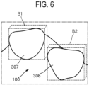
- FIG. 6 is a view for explaining a process of generating a boundary box in the archline optimization method according to the present disclosure
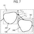
- FIG. 7 is a view for explaining a process of generating the central point from the boundary box.
- the points include the central point generated through the outer surfaces of boundary boxes of the teeth.
- the central point may be generated in the middle of the teeth included in the three-dimensional model, and the central point may be generated at one ends of the teeth when viewed from the side of the three-dimensional model.
- the central point may be generated between boundary boxes of incisors among the teeth.
- Each boundary box may have a rectangular parallelepiped structure enclosing a specific tooth, and the enclosed tooth does not protrude outside the boundary box.
- the boundary box may be formed to a size that minimizes an empty space between the boundary box and the tooth while enclosing the tooth.
- tooth #7 307 and tooth #8 308 are formed as incisors, and boundary boxes B1 and B2 enclosing the incisors, respectively, are formed.
- the central point may be the center of a line connecting front opposite vertices of the boundary boxes of the incisors. More specifically, the front vertex P 11' of the first boundary box B1 and the front vertex P12' of the second boundary box B2 are connected to generate a virtual first line 11, and the center of the first line 11 may be determined as the central point P1'. By determining the central point P 1' in this way, it is possible to reduce the number of points used to generate the left Spee curve and the right Spee curve, thereby saving system resources.
- the central point P1' is not generated only by being limited to the above-described contents, and one point of the boundary box enclosing each incisor may be determined as the central point P1'.
- one point of the boundary box enclosing each incisor may be determined as the central point P1'.
- the central point P1' on the side including tooth #1 301 to tooth #7 307 may be one point at a corner where the front surface and the upper surface meet in the boundary box B1 of tooth #7 307.
- the central point P1' on the side including tooth #8 308 to tooth #14 314 may be one point at a corner where the front surface and the upper surface meet in the boundary box B2 of tooth #8 308.
- the central point P1' on the side including tooth #8 308 to tooth #14 314 may be one point at a corner where the front surface and the upper surface meet in the boundary box B2 of tooth #8 308.
- the central point P1' may be determined as a point at which the slope inclination on the plane becomes 0 in the archline to be described later, and any method capable of expressing the foremost portion of the teeth may be used.
- FIG. 8 is for explaining a process of generating a side point P2' from the three-dimensional model 100.
- the side point may be a point formed at a predetermined distance from the initial archline 200.
- at least some of the points may be generated at an intersection between a line passing through the contour point of the molar tooth among the teeth and tangent to the contour of the molar tooth and a line horizontal to the rearmost contour point of the molar tooth.
- the side point among the points may be generated at a line tangent to the contour of the molar tooth and a line horizontal to the rearmost contour point of the molar tooth.
- the contour point of the molar tooth may be a reference point on an archline tangent to the contours of at least some of the teeth. More specifically, on the basis of the patient having 14 teeth in the maxilla, the contour point of the molar tooth may set the contour point Pa of tooth #1 301 as the reference point. When generating another side point, the contour point of the molar tooth may set the contour point Pf of tooth #14 314 as the reference point. However, it is not necessarily limited thereto, and tooth #3 303, tooth #6 306, and the like may be used as needed.
- the slope of a second line l2 passing through the contour point of the molar tooth and tangent to the contour of the molar tooth may be the same as the slope of the initial archline 200 at the tooth #1 contour point Pa.
- the tooth #1 contour point Pa corresponds to the contour point P21 of the molar tooth.
- the initial archline 200 is formed in the form of a three-dimensional curve, and the slope of the second line l2 is also formed to be the same as the instantaneous slope of the initial archline 200 at the tooth #1 contour point Pa. That is, the second line l2 may act like an extension of the initial archline 200.
- the rearmost contour point P22 may mean a contour point located at the rearmost of tooth #1 301.
- a third line l3 may be formed to pass through the rearmost contour point P22 and tangent to the contour of tooth #1 301.
- the third line l3 may be formed parallel to one corner of the boundary box enclosing tooth #1 301 and passing through the rearmost contour point P22.
- the first side point P2' generated at tooth #1 301 may be generated at a point where the second line l2 and the third line l3 extend and intersect.
- the first side point P2 may also be generated at the same location as or higher than the contour point P21 of the molar tooth.
- the central point for the incisor may express a portion where a tooth is located in the foremost of the three-dimensional model 100
- the first side point P2' may express a portion where a tooth is located in the rearmost of the three-dimensional model 100.
- the above-described contents have been described as an example of a method of generating the first side point P2' which is one side of the three-dimensional model 100, but the second side point (not shown), which is another side, may also be generated using the same method.
- FIG. 9 is a view for explaining a process of generating the side point from the three-dimensional model according to another embodiment.
- another contour point P23 of the molar tooth may be a point at which a buccal line bl passing through the center P24 of a tooth and the contour of the molar tooth intersect.
- the molar tooth may be tooth #1 301.
- the buccal line bl may mean a line extending from the center of the virtual circle toward the center P24 of the tooth.
- another first side point P3' may be determined as a specific point spaced apart by a predetermined distance from another contour point P23 of tooth #1 301.
- the another first side point P3' may be determined as a specific point on the third line l3 spaced apart from the another contour point P23 of tooth #1 301.
- another first side point P3' may be determined as a point at which a line extending from another contour point P23 and the third line l3 meet. More specifically, a fourth line l4 having a direction perpendicular to the buccal line bl may be formed at the another contour point P23 of tooth #1 301. The fourth line l4 may extend in one or both directions and may intersect the third line l3 passing through the rearmost contour point P22. At this time, a point at which the third line l3 and the fourth line l4 intersect may be determined as the another first side point P3'.
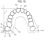
- FIG. 10 is a view for explaining a process of projecting a central point on a predetermined plane.
- the archline optimization method according to the present disclosure further includes the step S150 of projecting points on the predetermined plane.
- the central point P 1' and the first side point P2' may be projected.
- the points may be projected on the plane including a side point generated based on a molar tooth among the teeth.
- a projection plane T1 including the first side point P2' may be formed.
- the projection plane T1 may have a normal vector parallel to the third line l3.
- the central point P1' may be projected at the shortest distance on the projection plane T1.
- the central point P1' may be projected perpendicular to the projection plane T1.
- the projected central point P1 is generated, and the first side point P2' and the projected first side point P2 may be the same.
- the projected central point P1 and the projected first side point P2 may be disposed on the same plane.
- the projection plane T1 includes the first side point P2'
- the first side point P2' and the projected first side point P2 may be the same, so that the process of projecting the first side point P2' can be omitted and the system resources can be saved.
- the points can be projected on the plane including the side point, and it will also be possible for the points to be projected on a plane that does not include any points.
- FIG. 11 and 12 are for explaining a process of generating a Spee curve on the side of the three-dimensional model.
- the projected central point P1 and the projected first side point P2 disposed on the same projection plane T1 constitute an arc of a circle having a predetermined curvature radius d, and a Spee curve 400 may be generated (S160) based on the arc.
- the Spee curve 400 may be a two-dimensional arc which is a portion of the circumference, and the projected central point P1 and the projected first side point P2, which are the projected points, may form both ends of the Spee curve 400.
- the Spee curve connects the projected central point P1 and the projected first side point P2 with a curve, and may have a curvature radius d minimizing a deviation from the ends of the teeth.
- the curvature radius d may be determined to minimize a distance deviation between the Spee curve 400 and the ends of the teeth constituting the maxilla.
- the distance deviation the sum of distances, the sum of areas, or the root mean square of distances to the ends of the teeth on the basis of the Spee curve 400 may be used, but is not limited thereto, and any method for acquiring the optimal Spee curve 400 may be used.
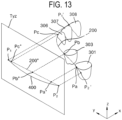
- FIG. 13 is a view for explaining a process of generating a Spee curve by projecting the central point P1' and the side point on a predetermined plane. Meanwhile, in FIG. 13 , only a portion necessary for convenience of description is shown, and the remaining portions are omitted.
- the central point P 1' and the first side point P2' may be generated in the three-dimensional model.
- the central point P1' and the first side point P2' may be projected onto a predetermined plane to generate the Spee curve 400, and the predetermined plane may be a yz projection plane Tyz.
- the yz projection plane Tyz may include the projected central point P1 and the projected first side point P2, and the Spee curve 400 including the projected central point P1 and the projected first side point P2" (400) may be acquired in the yz projection plane Tyz.
- the contour points Pa, Pb, and Pc of the teeth may be projected on the yz projection plane Tyz to form other projected contour points Pa", Pb", and Pc".
- an archline may be changed based on the generated Spee curve 400, and the changed archline may be applied to the three-dimensional model.
- the process of generating the Spee curve 400 using the central point P1' and the first side point P2' has been described, but it may also be possible to generate the Spee curve 400 using the central point P1' and another first side point P3'.
- step S170 of changing the three-dimensional archline based on the generated Spee curve 400 and applying it to the three-dimensional model will be described in detail.
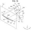
- FIG. 14 is a detailed flowchart of S170 in the archline optimization method according to the present disclosure, and FIGS. 15 and 16 are for explaining a process of changing the archline based on the generated Spee curve.
- the initial archline 200 may be changed based on the Spee curve 400 formed on a predetermined plane, and the changed archline is referred to as a final archline 500 for the sake of convenience.
- the step S170 of changing the archline includes a step S171 of projecting the initial archline 200 on the predetermined plane.
- the central point P1' and the first side point P2' may be projected on the yz projection plane Tyz to generate the projected central point P1 and the projected first side point P2, and the initial archline 200 can also be projected on the yz projection plane Tyz. That is, the three-dimensional initial archline 200 is projected on the yz projection plane Tyz to generate a second projected archline 200".
- a projection distance between the points constituting the three-dimensional initial archline 200 and the corresponding points of the second projected archline 200" generated when the three-dimensional initial archline 200 is projected on the yz projection plane Tyz may be measured.
- a step S172 of changing the position of the projected archline on which the initial archline 200 is projected (more specifically, the second projected archline 200") to the position of the Spee curve 400 generated on the predetermined plane may be performed.
- the position of the second projected archline 200" may be changed to the position of the Spee curve 400 generated on the yz projection plane Tyz, and more specifically, the z coordinate of the second projected archline 200" may be changed to correspond to the z coordinate of the Spee curve 400.
- the second projected archline 200" can be returned to the three-dimensional space by a projected distance (S173).
- the second projected archline 200" is changed to a position corresponding to the Spee curve 400 in the yz projection plane Tyz to generate a projected final archline 500'.
- the projected final archline 500' may be returned to the three-dimensional space and formed as the final archline 500, which is a new archline, of the three-dimensional model 100.
- the points constituting the projected final archline 500' are moved onto the three-dimensional space by an x-axis distance (projection distance) that has been moved when the initial archline 200 is projected on the yz projection plane Tyz, to form the final archline 500.
- the final archline 500 may have the same x coordinate and y coordinate as the initial archline 200, but may have the z coordinate optimized based on the Spee curve 400. That is, a shape obtained by projecting the final archline 500 on the yz projection plane Tyz may be the same as the Spee curve 400.
- the final archline 500 generated in this way can replace the initial archline 200, can express a natural smile line more optimized for the patient's oral cavity, as compared to the initial archline 200, and can provide an optimal treatment plan for the patient.
- the projected central point P1 and the projected first side point P2 are determined by projecting the central point P1' and the first side point P2', which are determined in the three-dimensional model, on the yz projection plane Tyz. Meanwhile, the projected central point P1 and the projected first side point P2 may be directly determined on the yz projection plane Tyz.
- the second projected archline 200" when the second projected archline 200" is generated, points located within a predetermined radius from both ends of the second projected archline 200" may be determined as the projected central point P1 and the projected first side point P2, respectively.
- the second projected archline 200" may be acquired by projecting at least two points included in the initial archline 200 on the yz projection plane Tyz.
- the at least two points may be the contour point Pa of tooth #1 301 and the contour point Pc of tooth #6 306.
- the projected contour points Pa" and Pc" may form both ends of the second projected archline 200", and arbitrary points within a predetermined radius range in the yz projection plane Tyz centered on each of the projected contour points Pa" and Pc" may be determined as the projected central point P1 and the projected first side point P2.
- the Spee curve 400 may be generated based on the projected central point P1 and the projected first side point P2.
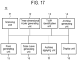
- FIG. 17 is a configuration diagram of the archline optimization apparatus 10 according to the present disclosure.
- the archline optimization apparatus 10 includes a scanning unit 11.
- the scanning unit 11 acquires image data of the inside of the patient's oral cavity.
- the image data of the inside of the patient's oral cavity may be image data of the actual patient's oral cavity or image data of a plaster model obtained by taking an impression of the oral cavity.
- the image data may be two-dimensional plane data, but is not limited thereto.
- the acquired image data may be stored in a database unit (not shown) of the archline optimization apparatus 10.
- the database unit may be a physical storage device or may mean a virtual cloud storage space.
- the archline optimization apparatus 10 includes a three-dimensional model generating unit 12.
- the three-dimensional model generating unit 12 converts the image data acquired from the scanning unit 11 into a three-dimensional model.
- the three-dimensional model expresses information on the inside of the patient's oral cavity including the teeth in a three-dimensional manner on a user interface, and the user can analyze the patient's oral cavity using the three-dimensional model and provide an optimal treatment plan.
- the archline optimization apparatus 10 may generate a Spee curve using at least a portion of the three-dimensional model and may use at least one of maxillary data and mandibular data as an example.
- the teeth are segmented by a tooth identification unit 13 so that each tooth can be individually identified.
- the tooth identification unit 13 may apply the characteristics of each tooth to the three-dimensional model by the database unit, identify teeth matching the corresponding characteristics, and assign tooth numbers to the identified teeth. For example, in the maxilla data, tooth numbers may be assigned sequentially from the left tooth, and a process of assigning the tooth numbers is the same as described above.
- the archline optimization apparatus 10 may include an archline generating unit 14.
- the archline generating unit 14 may generate an initial archline based on the three-dimensional model acquired by the three-dimensional model generating unit 12 and the data of the teeth individually identified by the tooth identification unit 13.
- the initial archline may be generated based on a predetermined tooth in the three-dimensional model of the teeth acquired by scanning the patient's teeth before orthodontic treatment. Since a process of generating the initial archline is the same as described above, detailed explanation thereof will not be repeated.
- the archline optimization apparatus 10 includes a point generating unit 15 that generates at least two points based on a plurality of teeth from the three-dimensional model.
- the point generating unit 15 may generate points to be used to generate a Spee curve.
- the points to be generated include at least one central point generated based on an incisor among the teeth and at least one side point generated based on a molar tooth among the teeth. For example, a first central point and a first side point may be generated to generate a first Spee curve on the left side of the three-dimensional model, and a second central point and a second side point can be generated to generate a second Spee curve on the right side of the three-dimensional model.
- the first central point and the second central point may be the same.
- the central point may be generated through the outer surface of the boundary box of specific teeth, and the specific teeth may be incisors including teeth #7 and #8 on the basis of the oral cavity of the patient having 14 teeth in the maxilla. More specifically, the central point may be the center of a first line connecting front opposite vertices of the boundary boxes of the incisors. In this way, by using the same central point when generating the first and second Spee curves, there is an advantage in that the system resources can be saved.
- the point generating unit 15 may generate side points, and the generated side points may be generated at an intersection between a line passing through the contour point of the molar tooth and tangent to the contour of the molar tooth and a line horizontal to the rearmost contour point of the molar tooth.
- the molar tooth may be tooth #1.
- the contour point of the molar tooth may be a reference point on an archline passing through the contours of at least some of the teeth, and the archline may be generated by the archline generating unit 14.
- the archline may be a three-dimensional line expressing the shape of the dental arch, and the archline may be formed to pass through the contours of tooth #1, tooth #3, and tooth #6.
- the side point may be generated by an intersection between a line perpendicular to the buccal line and a line horizontal to the rearmost contour point of the molar tooth.
- a process of generating the side points is the same as described above.
- a Spee curve generating unit 16 projects the generated points (the central point and the side point) on a predetermined projection plane.
- the Spee curve generating unit 16 may generate a projection plane including the side point and may project the central point on the projection plane as the shortest distance.
- the projection plane may be generated to be parallel to the yz plane, and since the central point is projected on the projection plane, the Spee curve may be flatly displayed when the three-dimensional model is viewed from one side.
- the projection plane does not necessarily include the side point, but points may be projected on the projection plane that does not include the central point and the side point, so that a Spee curve can be generated.
- the Spee curve generating unit 16 may generate the Spee curve so that the projected points form an arc having a predetermined radius of curvature from a predetermined center of curvature.
- the center of curvature may be placed outside the three-dimensional model, and the radius of curvature may be determined as a value that minimizes a deviation of the Spee curve from the ends of the teeth. In this way, since the Spee curve is determined as a value that minimizes the deviation from the ends of the teeth, it is possible to acquire a Spee curve that most closely matches the actual oral cavity.
- the archline optimization apparatus 10 further includes an archline applying unit 17.
- the archline applying unit 17 may change the initial archline into the final archline based on the Spee curve generated by the Spee curve generating unit 16.
- the changed archline i.e., the final archline
- the archline applying unit 17 projects the initial archline on a predetermined plane, generates the projected final archline by matching the projected initial archline to the Spee curve generated by the Spee curve generating unit 16, and returns the final archline to the three-dimensional space.
- the display unit 18 may be a component that allows the user to visually recognize the processes performed by the archline optimization apparatus 10, and may be, for example, a monitor device, a tablet device, and the like.
- the user can visually and easily check at least one of the generated initial archline, Spee curve, and final archline through the display unit 18, and can establish a treatment plan suitable for the patient based on the acquired final archline.
- the present disclosure provides an archline optimization method for providing a patient-specific treatment plan to a patient by generating a Spee curve in a three-dimensional model representing the oral cavity of a patient and optimizing an archline based on the generated Spee curve, and an apparatus using the same.
Landscapes
- Health & Medical Sciences (AREA)
- Engineering & Computer Science (AREA)
- Life Sciences & Earth Sciences (AREA)
- Veterinary Medicine (AREA)
- Dentistry (AREA)
- Epidemiology (AREA)
- Oral & Maxillofacial Surgery (AREA)
- Animal Behavior & Ethology (AREA)
- General Health & Medical Sciences (AREA)
- Public Health (AREA)
- General Engineering & Computer Science (AREA)
- Computer Graphics (AREA)
- Architecture (AREA)
- Computer Hardware Design (AREA)
- Software Systems (AREA)
- Physics & Mathematics (AREA)
- General Physics & Mathematics (AREA)
- Theoretical Computer Science (AREA)
- Biomedical Technology (AREA)
- Biophysics (AREA)
- Dental Tools And Instruments Or Auxiliary Dental Instruments (AREA)
Applications Claiming Priority (3)
| Application Number | Priority Date | Filing Date | Title |
|---|---|---|---|
| KR20200143824 | 2020-10-30 | ||
| KR1020210044417A KR102590774B1 (ko) | 2020-10-30 | 2021-04-06 | 아치라인 최적화 방법 및 이를 이용한 장치 |
| PCT/KR2021/015402 WO2022092882A1 (ko) | 2020-10-30 | 2021-10-29 | 아치라인 최적화 방법 및 이를 이용한 장치 |
Publications (3)
| Publication Number | Publication Date |
|---|---|
| EP4238531A1 true EP4238531A1 (de) | 2023-09-06 |
| EP4238531A4 EP4238531A4 (de) | 2024-10-09 |
| EP4238531B1 EP4238531B1 (de) | 2025-11-26 |
Family
ID=81384313
Family Applications (1)
| Application Number | Title | Priority Date | Filing Date |
|---|---|---|---|
| EP21886876.8A Active EP4238531B1 (de) | 2020-10-30 | 2021-10-29 | Verfahren zur optimierung einer bogenlinie |
Country Status (3)
| Country | Link |
|---|---|
| US (1) | US12508104B2 (de) |
| EP (1) | EP4238531B1 (de) |
| WO (1) | WO2022092882A1 (de) |
Family Cites Families (11)
| Publication number | Priority date | Publication date | Assignee | Title |
|---|---|---|---|---|
| KR100209707B1 (ko) | 1996-12-03 | 1999-07-15 | 구본준 | 반도체 소자의 콘택배선 형성방법 |
| EP1191896B1 (de) | 1999-05-13 | 2008-06-25 | Align Technology, Inc. | System zur bestimmung der endgültigen position von zähnen |
| US7361018B2 (en) | 2003-05-02 | 2008-04-22 | Orametrix, Inc. | Method and system for enhanced orthodontic treatment planning |
| US9326831B2 (en) | 2006-10-20 | 2016-05-03 | Align Technology, Inc. | System and method for positioning three-dimensional brackets on teeth |
| JP5337472B2 (ja) * | 2008-12-24 | 2013-11-06 | イマグノーシス株式会社 | 医用三次元画像における切断面画像の表示方法、医用三次元画像の表示装置および医用画像表示プログラム |
| CN105769352B (zh) | 2014-12-23 | 2020-06-16 | 无锡时代天使医疗器械科技有限公司 | 用于产生牙齿矫治状态的直接分步法 |
| KR102073479B1 (ko) | 2018-06-25 | 2020-02-04 | 오스템임플란트 주식회사 | 치아 셋업 과정에서 악궁 라인을 자동으로 생성하는 장치 및 그 방법 |
| KR102097070B1 (ko) * | 2018-07-16 | 2020-04-03 | 김정일 | 자동 치열 교정 데이터 생성방법 |
| WO2020026117A1 (en) | 2018-07-31 | 2020-02-06 | 3M Innovative Properties Company | Method for automated generation of orthodontic treatment final setups |
| US11589955B2 (en) * | 2018-09-27 | 2023-02-28 | Align Technology, Inc. | Aligner damage prediction using machine learning |
| CN114080196A (zh) * | 2019-04-11 | 2022-02-22 | 坎迪德护理公司 | 牙科对准器和用于对齐牙齿的步骤 |
-
2021
- 2021-10-29 WO PCT/KR2021/015402 patent/WO2022092882A1/ko not_active Ceased
- 2021-10-29 US US18/034,279 patent/US12508104B2/en active Active
- 2021-10-29 EP EP21886876.8A patent/EP4238531B1/de active Active
Also Published As
| Publication number | Publication date |
|---|---|
| US12508104B2 (en) | 2025-12-30 |
| WO2022092882A1 (ko) | 2022-05-05 |
| US20230404708A1 (en) | 2023-12-21 |
| EP4238531A4 (de) | 2024-10-09 |
| EP4238531B1 (de) | 2025-11-26 |
Similar Documents
| Publication | Publication Date | Title |
|---|---|---|
| US12239506B2 (en) | Methods for visualizing treatment outcomes | |
| AU2020275774B2 (en) | Visual presentation of gingival line generated based on 3D tooth model | |
| US10952817B1 (en) | Systems and methods for determining orthodontic treatments | |
| US10537405B2 (en) | Dental appliance with cavity for an unerupted or erupting tooth | |
| KR102073479B1 (ko) | 치아 셋업 과정에서 악궁 라인을 자동으로 생성하는 장치 및 그 방법 | |
| US8706672B2 (en) | Computer-assisted creation of a custom tooth set-up using facial analysis | |
| US10945811B1 (en) | Systems and methods for determining orthodontic treatments | |
| CN105596094A (zh) | 正畸间接粘接转移托盘三维数字化模型的生成方法及装置 | |
| US12414845B2 (en) | Generation of a three-dimensional digital model of a replacement tooth | |
| KR102590774B1 (ko) | 아치라인 최적화 방법 및 이를 이용한 장치 | |
| US12508104B2 (en) | Method for optimizing archline and apparatus using same | |
| CN116710024A (zh) | 优化弓形线的方法和使用该方法的装置 | |
| WO2025074322A1 (en) | Combined orthodontic and dental restorative treatments | |
| US20250391136A1 (en) | Concurrent adjusting of tooth models | |
| US20250384642A1 (en) | Relative mirroring for simultaneous adjustment of multiple tooth models | |
| KR102944869B1 (ko) | 임플란트 수술 계획 수립 방법 및 그 장치 | |
| KR20260000009A (ko) | 치아 위치정보 제공 방법 및 그 장치 |
Legal Events
| Date | Code | Title | Description |
|---|---|---|---|
| STAA | Information on the status of an ep patent application or granted ep patent |
Free format text: STATUS: THE INTERNATIONAL PUBLICATION HAS BEEN MADE |
|
| PUAI | Public reference made under article 153(3) epc to a published international application that has entered the european phase |
Free format text: ORIGINAL CODE: 0009012 |
|
| STAA | Information on the status of an ep patent application or granted ep patent |
Free format text: STATUS: REQUEST FOR EXAMINATION WAS MADE |
|
| 17P | Request for examination filed |
Effective date: 20230505 |
|
| AK | Designated contracting states |
Kind code of ref document: A1 Designated state(s): AL AT BE BG CH CY CZ DE DK EE ES FI FR GB GR HR HU IE IS IT LI LT LU LV MC MK MT NL NO PL PT RO RS SE SI SK SM TR |
|
| DAV | Request for validation of the european patent (deleted) | ||
| DAX | Request for extension of the european patent (deleted) | ||
| A4 | Supplementary search report drawn up and despatched |
Effective date: 20240909 |
|
| RIC1 | Information provided on ipc code assigned before grant |
Ipc: A61C 19/05 20060101ALI20240903BHEP Ipc: A61C 9/00 20060101ALI20240903BHEP Ipc: A61C 7/00 20060101AFI20240903BHEP |
|
| GRAP | Despatch of communication of intention to grant a patent |
Free format text: ORIGINAL CODE: EPIDOSNIGR1 |
|
| STAA | Information on the status of an ep patent application or granted ep patent |
Free format text: STATUS: GRANT OF PATENT IS INTENDED |
|
| INTG | Intention to grant announced |
Effective date: 20250725 |
|
| GRAS | Grant fee paid |
Free format text: ORIGINAL CODE: EPIDOSNIGR3 |
|
| GRAA | (expected) grant |
Free format text: ORIGINAL CODE: 0009210 |
|
| STAA | Information on the status of an ep patent application or granted ep patent |
Free format text: STATUS: THE PATENT HAS BEEN GRANTED |
|
| AK | Designated contracting states |
Kind code of ref document: B1 Designated state(s): AL AT BE BG CH CY CZ DE DK EE ES FI FR GB GR HR HU IE IS IT LI LT LU LV MC MK MT NL NO PL PT RO RS SE SI SK SM TR |
|
| REG | Reference to a national code |
Ref country code: CH Ref legal event code: F10 Free format text: ST27 STATUS EVENT CODE: U-0-0-F10-F00 (AS PROVIDED BY THE NATIONAL OFFICE) Effective date: 20251126 Ref country code: GB Ref legal event code: FG4D |
|
| REG | Reference to a national code |
Ref country code: DE Ref legal event code: R096 Ref document number: 602021043342 Country of ref document: DE |
|
| REG | Reference to a national code |
Ref country code: IE Ref legal event code: FG4D |
|
| REG | Reference to a national code |
Ref country code: NL Ref legal event code: MP Effective date: 20251126 |
|
| PG25 | Lapsed in a contracting state [announced via postgrant information from national office to epo] |
Ref country code: ES Free format text: LAPSE BECAUSE OF FAILURE TO SUBMIT A TRANSLATION OF THE DESCRIPTION OR TO PAY THE FEE WITHIN THE PRESCRIBED TIME-LIMIT Effective date: 20251126 |
|
| REG | Reference to a national code |
Ref country code: LT Ref legal event code: MG9D |
|
| PG25 | Lapsed in a contracting state [announced via postgrant information from national office to epo] |
Ref country code: NO Free format text: LAPSE BECAUSE OF FAILURE TO SUBMIT A TRANSLATION OF THE DESCRIPTION OR TO PAY THE FEE WITHIN THE PRESCRIBED TIME-LIMIT Effective date: 20260226 |
|
| PG25 | Lapsed in a contracting state [announced via postgrant information from national office to epo] |
Ref country code: HR Free format text: LAPSE BECAUSE OF FAILURE TO SUBMIT A TRANSLATION OF THE DESCRIPTION OR TO PAY THE FEE WITHIN THE PRESCRIBED TIME-LIMIT Effective date: 20251126 Ref country code: FI Free format text: LAPSE BECAUSE OF FAILURE TO SUBMIT A TRANSLATION OF THE DESCRIPTION OR TO PAY THE FEE WITHIN THE PRESCRIBED TIME-LIMIT Effective date: 20251126 Ref country code: AT Free format text: LAPSE BECAUSE OF FAILURE TO SUBMIT A TRANSLATION OF THE DESCRIPTION OR TO PAY THE FEE WITHIN THE PRESCRIBED TIME-LIMIT Effective date: 20251126 |
|
| REG | Reference to a national code |
Ref country code: AT Ref legal event code: MK05 Ref document number: 1860319 Country of ref document: AT Kind code of ref document: T Effective date: 20251126 |
|
| PG25 | Lapsed in a contracting state [announced via postgrant information from national office to epo] |
Ref country code: NL Free format text: LAPSE BECAUSE OF FAILURE TO SUBMIT A TRANSLATION OF THE DESCRIPTION OR TO PAY THE FEE WITHIN THE PRESCRIBED TIME-LIMIT Effective date: 20251126 |
|
| PG25 | Lapsed in a contracting state [announced via postgrant information from national office to epo] |
Ref country code: RS Free format text: LAPSE BECAUSE OF FAILURE TO SUBMIT A TRANSLATION OF THE DESCRIPTION OR TO PAY THE FEE WITHIN THE PRESCRIBED TIME-LIMIT Effective date: 20260226 |
|
| PG25 | Lapsed in a contracting state [announced via postgrant information from national office to epo] |
Ref country code: IS Free format text: LAPSE BECAUSE OF FAILURE TO SUBMIT A TRANSLATION OF THE DESCRIPTION OR TO PAY THE FEE WITHIN THE PRESCRIBED TIME-LIMIT Effective date: 20260326 |
|
| PG25 | Lapsed in a contracting state [announced via postgrant information from national office to epo] |
Ref country code: PT Free format text: LAPSE BECAUSE OF FAILURE TO SUBMIT A TRANSLATION OF THE DESCRIPTION OR TO PAY THE FEE WITHIN THE PRESCRIBED TIME-LIMIT Effective date: 20260326 |
|
| PG25 | Lapsed in a contracting state [announced via postgrant information from national office to epo] |
Ref country code: PL Free format text: LAPSE BECAUSE OF FAILURE TO SUBMIT A TRANSLATION OF THE DESCRIPTION OR TO PAY THE FEE WITHIN THE PRESCRIBED TIME-LIMIT Effective date: 20251126 |
|
| PG25 | Lapsed in a contracting state [announced via postgrant information from national office to epo] |
Ref country code: LV Free format text: LAPSE BECAUSE OF FAILURE TO SUBMIT A TRANSLATION OF THE DESCRIPTION OR TO PAY THE FEE WITHIN THE PRESCRIBED TIME-LIMIT Effective date: 20251126 |