EP4238317B1 - Automatische kalibrierung einer mikrofonanordnung für telepräsenzkonferenzen - Google Patents
Automatische kalibrierung einer mikrofonanordnung für telepräsenzkonferenzen Download PDFInfo
- Publication number
- EP4238317B1 EP4238317B1 EP20816861.7A EP20816861A EP4238317B1 EP 4238317 B1 EP4238317 B1 EP 4238317B1 EP 20816861 A EP20816861 A EP 20816861A EP 4238317 B1 EP4238317 B1 EP 4238317B1
- Authority
- EP
- European Patent Office
- Prior art keywords
- array
- microphone
- loudspeaker
- microphones
- loudspeakers
- Prior art date
- Legal status (The legal status is an assumption and is not a legal conclusion. Google has not performed a legal analysis and makes no representation as to the accuracy of the status listed.)
- Active
Links
Images


Classifications
-
- H—ELECTRICITY
- H04—ELECTRIC COMMUNICATION TECHNIQUE
- H04R—LOUDSPEAKERS, MICROPHONES, GRAMOPHONE PICK-UPS OR LIKE ACOUSTIC ELECTROMECHANICAL TRANSDUCERS; DEAF-AID SETS; PUBLIC ADDRESS SYSTEMS
- H04R1/00—Details of transducers, loudspeakers or microphones
- H04R1/20—Arrangements for obtaining desired frequency or directional characteristics
- H04R1/32—Arrangements for obtaining desired frequency or directional characteristics for obtaining desired directional characteristic only
- H04R1/40—Arrangements for obtaining desired frequency or directional characteristics for obtaining desired directional characteristic only by combining a number of identical transducers
- H04R1/403—Arrangements for obtaining desired frequency or directional characteristics for obtaining desired directional characteristic only by combining a number of identical transducers loud-speakers
-
- H—ELECTRICITY
- H04—ELECTRIC COMMUNICATION TECHNIQUE
- H04R—LOUDSPEAKERS, MICROPHONES, GRAMOPHONE PICK-UPS OR LIKE ACOUSTIC ELECTROMECHANICAL TRANSDUCERS; DEAF-AID SETS; PUBLIC ADDRESS SYSTEMS
- H04R1/00—Details of transducers, loudspeakers or microphones
- H04R1/20—Arrangements for obtaining desired frequency or directional characteristics
- H04R1/32—Arrangements for obtaining desired frequency or directional characteristics for obtaining desired directional characteristic only
- H04R1/40—Arrangements for obtaining desired frequency or directional characteristics for obtaining desired directional characteristic only by combining a number of identical transducers
- H04R1/406—Arrangements for obtaining desired frequency or directional characteristics for obtaining desired directional characteristic only by combining a number of identical transducers microphones
-
- H—ELECTRICITY
- H04—ELECTRIC COMMUNICATION TECHNIQUE
- H04R—LOUDSPEAKERS, MICROPHONES, GRAMOPHONE PICK-UPS OR LIKE ACOUSTIC ELECTROMECHANICAL TRANSDUCERS; DEAF-AID SETS; PUBLIC ADDRESS SYSTEMS
- H04R29/00—Monitoring arrangements; Testing arrangements
- H04R29/001—Monitoring arrangements; Testing arrangements for loudspeakers
- H04R29/002—Loudspeaker arrays
-
- H—ELECTRICITY
- H04—ELECTRIC COMMUNICATION TECHNIQUE
- H04R—LOUDSPEAKERS, MICROPHONES, GRAMOPHONE PICK-UPS OR LIKE ACOUSTIC ELECTROMECHANICAL TRANSDUCERS; DEAF-AID SETS; PUBLIC ADDRESS SYSTEMS
- H04R29/00—Monitoring arrangements; Testing arrangements
- H04R29/004—Monitoring arrangements; Testing arrangements for microphones
- H04R29/005—Microphone arrays
-
- H—ELECTRICITY
- H04—ELECTRIC COMMUNICATION TECHNIQUE
- H04R—LOUDSPEAKERS, MICROPHONES, GRAMOPHONE PICK-UPS OR LIKE ACOUSTIC ELECTROMECHANICAL TRANSDUCERS; DEAF-AID SETS; PUBLIC ADDRESS SYSTEMS
- H04R3/00—Circuits for transducers, loudspeakers or microphones
- H04R3/005—Circuits for transducers, loudspeakers or microphones for combining the signals of two or more microphones
-
- H—ELECTRICITY
- H04—ELECTRIC COMMUNICATION TECHNIQUE
- H04R—LOUDSPEAKERS, MICROPHONES, GRAMOPHONE PICK-UPS OR LIKE ACOUSTIC ELECTROMECHANICAL TRANSDUCERS; DEAF-AID SETS; PUBLIC ADDRESS SYSTEMS
- H04R3/00—Circuits for transducers, loudspeakers or microphones
- H04R3/12—Circuits for transducers, loudspeakers or microphones for distributing signals to two or more loudspeakers
Definitions
- This description relates to calibration of microphones and loudspeakers used in applications such as telepresence conferencing.
- a telepresence conferencing system can include a large number of microphones to detect directional audio signals from a user and a plurality of loudspeakers to provide directional audio signals to the user.
- Methods for calibration of microphones and loudspeakers are disclosed in US 2013/170666 A1 and US 2017/127206 A1 .
- the proposed solution relates to a method as stated in claim 1 of the accompanying claim set, a method as stated in claim 13, a computer program product as stated in claim 14 and an electronic apparatus as stated in claim 15.
- each microphone of the array may be calibrated (e.g., the gain of the microphone) relative to the other microphones.
- each loudspeaker must also be calibrated (e.g., the gain of the loudspeaker) relative to the other loudspeakers.
- Conventional approaches to performing such calibrations involve using external hardware, e.g., a sound source and a microphone located at the anticipated position of a user/speaker in the telepresence conferencing system.
- a technical solution to the above-described technical problem includes generating calibration filters for microphones and/or speakers by deriving power spectral densities at each microphone in response to signals generated by each loudspeaker.
- a computer within an improved telepresence system can measure a raw impulse response function corresponding to each channel, i.e., each loudspeaker/microphone pair.
- the computer normalizes the raw impulse response function based on contributions of different reverberant reflections to a reverberant sound field energy.
- the computer then extracts a sub-segment of each impulse response function between a start time and a finish time after a time at which the signal was generated by the loudspeaker.
- the computer then generates a white-noise power spectral density for each channel based on the sub-segments.
- the calibration function for a microphone is then based on a reciprocal of the power spectral density averaged over the loudspeakers.
- the calibration function for a loudspeaker is then based on a reciprocal of the power spectral density averaged over the microphones.
- a technical advantage of the above-described technical solution is that the technical solution is insensitive to room configuration and may be performed automatically without human involvement.
- the technical solution is also insensitive to hardware configuration, e.g., positions of microphones and loudspeakers with respect to each other. Further, the technical solution does not require any external hardware beyond the hardware that already exists in the telepresence system. In essence, a user may cause the calibration filters to be generated by simply flipping a switch.
- the computer normalizes the raw impulse response functions for all channels with an impulse-response energy averaged across loudspeakers and microphones.
- the start time is based on a distance traveled by an echo in a reverberant sound field.
- the finish time is based on a noise-floor associated with the measurement process.
- the white-noise power spectral density for a channel is based on a Fourier transform of a white-noise autocorrelation of the sub-segment for that channel. In some implementations, the Fourier transform is taken over a windowed version of the white-noise autocorrelation function.
- FIG. 1A is a diagram that illustrates an example electronic environment 100 in which the above-described improved techniques may be implemented. As shown in FIG. 1A , the example electronic environment 100 includes a computer 120.
- the computer 120 includes a network interface 122, one or more processing units 124, and memory 126.
- the network interface 122 includes, for example, Ethernet adaptors, and the like, for converting electronic and/or optical signals received from a network to electronic form for use by the computer 120.
- the set of processing units 124 include one or more processing chips and/or assemblies.
- the memory 126 includes both volatile memory (e.g., RAM) and non-volatile memory, such as one or more ROMs, disk drives, solid state drives, and the like.
- the set of processing units 124 and the memory 126 together form control circuitry, which is configured and arranged to carry out various methods and functions as described herein.
- one or more of the components of the computer 120 can include processors (e.g., processing units 124) configured to process instructions stored in the memory 126. Examples of such instructions as depicted in FIG. 1 include a reverberant sound field manager 130, an impulse response manager 140, a power spectral density manager 150, and a calibration filter manager 160. Further, as illustrated in FIG. 1 , the memory 126 is configured to store various data, which is described with respect to the respective managers that use such data.
- the reverberant sound field manager 130 is configured to generate reverberant sound field data 132, which represents a reverberant sound field produced by loudspeakers and used to measure impulse responses at the microphones.
- the sound field is reverberant because, once converted to an audio signal at a loudspeaker, the audio signal may be reflected off nearby walls, ceilings, floors, and objects in a room in which the computer 120, loudspeakers, and microphones are contained.
- the reverberant sound field data 132 is produced via a signal of a particular mathematical form emanating from a loudspeaker that lends itself to measuring a frequency response of a microphone with a high signal to noise ratio (SNR).
- the reverberant sound field data 132 is then derived from reflections from, e.g., walls, ceiling, floor, and objects in a room that includes the computer 120, microphones, and loudspeakers.
- the mathematical form includes a swept sine chirp signal represented by swept sine chirp data 134.
- This swept sine chirp signal has an advantage of mitigating effects of loudspeaker nonlinearity from the measurement of the frequency response at a microphone.
- the impulse response manager 140 is configured to generate impulse response data 144 representing impulse response functions, h ( m , s , t ), for loudspeaker-microphone channels, where m represents a microphone index identifying a microphone of a microphone array, s represents a loudspeaker index identifying a loudspeaker of a loudspeaker array, and t represents the time. Accordingly, each pair ( m , s ) represents a channel over which the impulse response manager 140 measures a raw impulse response function, h ( m , s , t ), from the reverberant sound field data 132.
- the impulse response manager 140 includes a decay normalization manager 141 and/or a sub-segment manager 142.
- the decay normalization manager 141 is configured to provide a consistent normalization factor over the multiple channels, the normalization factor being represented by normalization data 145.
- the normalization factor is used to normalize the contributions of different reverberant reflections to the computations for the calibration filters for the microphones and loudspeakers. This normalization factor makes it possible for the calibration results to be insensitive to hardware configuration.
- the decay normalization manager 141 is configured to estimate an impulse response energy e ( m , s , t ) as a function of time for each channel. In some implementations, the decay normalization manager 141 performs such an estimation by temporally smoothing the square of the impulse response functions, h ( m , s , t ) 2 .
- the decay normalization manager 141 performs the temporal smoothing by performing a moving average of the impulse response data over a specified time duration, e.g., 1.5 ms, although the duration may be smaller or larger than 1.5 ms. In some implementations, the decay normalization manager 141 compensates for delay induced by the temporal smoothing to time-align the energy estimate with the corresponding impulse response.
- the sub-segment manager 142 is configured to extract a time-based sub-segment of the impulse response functions h ( m , s , t ) between a first time and a second time to produce sub-segment data 146 representing an impulse response sub-segment h analysis ( m,s,t ).
- the first time is based on a distance traveled by an echo (i.e., a reverberant sound field reflected off a wall, ceiling, floor, or object). Defining the first time in such a manner may mitigate distance-related energy effects. For example, for a sound velocity of 343 m/s, a delay of 45 ms relative to an onset of an impulse response corresponds to a distance of about 15.4 m traveled by an echo.
- the power spectral density manager 150 is configured to produce power spectral density data 154 based on the impulse response data 144.
- the power spectral data 154 represents a white-noise power spectral density S analysis ( m , s , f ), where f is a frequency.
- the power spectral density manager 150 includes a convolution manager 151 and a transform manager 152.
- the convolution manager 151 is configured to perform a convolution on time-based functions to produce autocorrelation data 155 representing another time-based function. Specifically, the convolution manager 151 is configured to generate autocorrelation functions from the impulse response functions for each microphone and loudspeaker.
- the transform manager 152 is configured to perform a transform to frequency space of a time-based function.
- the time-based function on which the transform manager 152 performs a transform to frequency space is the autocorrelation function r analysis ( m , s , t ) to produce the power spectral density data 154 representing a power spectral density S analysis ( m , s , f ) .
- the transform manager 152 is configured to multiply the autocorrelation function r anavysis ( m , s , t ) by a window function W ( t ), represented by window data 156.
- the window function W ( t ) has a duration of 1 ms, although the duration can be greater than or less than 1 ms.
- the transform manager applies a Fourier transform to the product of r analysis ( m , s , t ) and W ( t ).
- the Fourier transform is performed using a Fast Fourier Transform implementation.
- the transform manager uses a wavelet transform to produce the transform to frequency space.
- the calibration filter manager 160 is configured to produce microphone calibration data 162 and/or loudspeaker calibration data 164. Specifically, the calibration filter manager 160 performs averaging operations on the power spectral density data 154 over (i) loudspeaker to produce a loudspeaker-averaged power spectral density S microphone ( m , f ), (ii) microphone to produce a microphone-averaged power spectral density S loudspeaker ( s , f ), and (iii) a microphone-and loudspeaker averaged power spectral density S avg ( f ).
- the microphones are calibrated to record the same spectrum in response to the same input stimulus, and the loudspeakers are calibrated to produce the same spectrum in response to the same input stimulus.
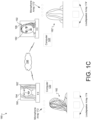
- FIG. 1B is a diagram that illustrates an example configuration 170 of microphones 172 and loudspeakers 174 and the computer 120 that can perform the calibration of the microphones 172 and loudspeakers 174.
- microphones 172 that may be used in the configuration 170 include Invensense ICS-52000 TDM microphones.
- Examples of loudspeakers 174 that may be used in the configuration 170 include Tymphany TC5FC07-04. It is noted that any number of microphones and loudspeakers may be considered.
- the telepresence system 180 is being used by a first user 182 and a second user 182'.
- the users 182 and 182' are using the telepresence system 180 to engage in a 3D telepresence session.
- the telepresence system 180 can allow each of the users 182 and 182' to see a highly realistic and visually congruent representation of the other, thereby facilitating the users to interact in a manner similar to being in the physical presence of each other.
- the telepresence system 180 can include one or more 2D or 3D displays.
- a 3D display 190 is provided for the user 182
- a 3D display 192 is provided for the user 182'.
- the 3D displays 190, 192 can use any of multiple types of 3D display technology to provide an autostereoscopic view for the respective viewer (here, the user 102 or user 104, for example).
- the 3D displays 190, 192 may be a standalone unit (e.g., self-supported or suspended on a wall).
- displays 190, 192 may be 2D displays.
- displays such as displays 190, 192 can provide imagery that approximates the 3D optical characteristics of physical objects in the real world without the use of a head-mounted display (HMD) device.
- the displays described herein include flat panel displays, lenticular lenses (e.g., microlens arrays), and/or parallax barriers to redirect images to a number of different viewing regions associated with the display.
- a user may be seated in the single location to experience proper parallax, minimal distortion, and realistic 3D images. If the user moves to a different physical location (or changes a head position or eye gaze position), the image content (e.g., the user, objects worn by the user, and/or other objects) may begin to appear less realistic, 2D, and/or distorted.
- the systems and techniques described herein may reconfigure the image content projected from the display to ensure that the user can move around, but still experience proper parallax, low rates of distortion, and realistic 3D images in real time.
- the systems and techniques described herein provide the advantage of maintaining and providing 3D image content and objects for display to a user regardless of any user movement that occurs while the user is viewing the 3D display.
- the telepresence system 180 can include one or more networks.
- the network 198 can be a publicly available network (e.g., the Internet), or a private network, to name just two examples.
- the network 198 can be wired, or wireless, or a combination of the two.
- the network 198 can include, or make use of, one or more other devices or systems, including, but not limited to, one or more servers (not shown).
- the telepresence system 180 further includes the microphone array 172 and loudspeaker array 174 for the user 182, as well as an analogous microphone array 172' and loudspeaker array 174' for the user 182'. These are arranged in order to provide the most realistic audio experience for the users 182 and 182'.
- the loudspeaker arrays 174 and 174' can provide 3D audio signals to the local and the microphone arrays 172 and 172' can be used to detect 3D audio signals from the user that then can be encoded and sent to the remote user for rendering of a 3D sound field to the remote user representing the sounds in the telepresence system 180.
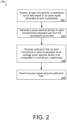
- FIG. 2 is a flow chart depicting an example method 200 of calibrating microphones and loudspeakers.
- the method 200 may be performed by software constructs described in connection with FIG. 1 , which reside in memory 126 of the user device computer 120 and are run by the set of processing units 124 or may be performed by software constructs which reside in memory of a computing device different from (e.g., remote from) user device computer 120.
- the impulse response manager 140 receives, via each microphone of an array of microphones, a reverberant sound field (e.g., reverberant sound field data 132) based on a signal (e.g., swept sine chirp signal data 134) generated by the reverberant sound field manager 130 at each loudspeaker of an array of loudspeakers.
- a signal e.g., swept sine chirp signal data 134
- the reverberant sound field manager 130 causes the swept sine chirp to be emitted from the array of loudspeakers.
- the swept sine chirp is emitted from each loudspeaker of the array of loudspeakers, one by one, separated in time.
- the swept sine chirp is emitted from a plurality of speakers of the array of loudspeakers all at the same time.
- each microphone of the array of microphones records the subsequent reverberant sound field over the duration at least as long the duration of the swept sine chirp, T , according to Eq. (1).
- the microphones record the subsequent reverberant sound field between a start time and an end time.
- the difference between the start and end time differs from T.
- the start time and/or end time are based on measured characteristics of the reverberant sound field.
- the start time may be based on a time at which direct sound to the microphone - that is, sound that undergoes no reflections and follows a direct path to the microphone - may be ignored.
- the reverberant sound field manager 130 may boost the amplitude of the reverberant sound field because the audio signal as reflected from boundaries and/or obstacles may suffer some degradation. Note that by using the reverberant, rather than direct, sound field, the calibrated microphones may generate high-quality directionally-sensitive audio signals.
- the power spectral density manager 150 generates, for each microphone of the array of microphones and for each loudspeaker of the array of loudspeakers, a respective power-spectral density (e.g., power spectral density data 154) for that microphone and that loudspeaker based on the respective reverberant sound field generated by that loudspeaker and received at that microphone.
- a respective power-spectral density e.g., power spectral density data 154
- the calibration filter manager 160 generates, for each microphone of the array of microphones, a respective calibration filter (e.g., microphone calibration data 162) based on a ratio of the power spectral density averaged over the array of loudspeakers and the array of microphones (Eq. (7)) and a power spectral density averaged over the array of loudspeakers (Eq. (5)).
- a respective calibration filter e.g., microphone calibration data 162
- the microphones are calibrated to record the same spectrum in response to the same input stimulus, and the loudspeakers are calibrated to produce the same spectrum in response to the same input stimulus.
- the calibration filters are based on a reverberant sound field, rather than direct sound fields, the calibration factors are largely insensitive to the geometry of the environment in which the loudspeakers and the microphones are place and any nodes in the direct sound signals, and the calibration filters cause the microphones to generate high-quality directionally-sensitive audio signals.
- the computer 120 records an acoustic signal from a user by the array of microphones using the respective calibration filters that were generated for each microphone of the array of microphones, with each microphone of the array of microphones recording essentially the same spectrum of the acoustic signal.
- the signals recorded from the calibrated microphones then can be processed to generate spatial audio signals representing the sound in the environment of the array of microphones (e.g., speech uttered by one or more speakers using a telepresence system that includes the array of microphones), and the generated spatial audio signals can be transmitted to a sound rendering system (e.g., a remote telepresence system) for rendering.
- a sound rendering system e.g., a remote telepresence system
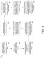
- FIG. 3 is a flow chart that illustrates an example process 300 for calibrating microphones of a microphone array.
- the process 300 may be performed by software constructs described in connection with FIG. 1 , which reside in memory 126 of the user device computer 120 and are run by the set of processing units 124 or may be performed by software constructs which reside in memory of a computing device different from (e.g., remote from) user device computer 120.
- the impulse response manager 140 measures a reverberant (raw) impulse response from each channel, i.e., each microphone/loudspeaker pair.
- the impulse response may be derived from reflections from walls, ceiling, floor, or objects received at a microphone originating from a swept sine chirp generated by the reverberant sound field manager 130.
- the actual recording of the signal occurs at a start time that occurs after a sufficient amount of time has passed after a direct audio signal has been received at a microphone. Accordingly, the reverberant sound field measured at a microphone includes only signals reflected from boundaries and obstacles.
- Example raw impulse response functions for two loudspeakers and four microphones are illustrated in FIG. 4A , making eight raw impulse response functions.
- each of the raw impulse response functions are measured based on a reverberant sound field from a single loudspeaker.
- each loudspeaker generates the swept sine chirp at different times.
- the raw impulse response functions are measured at the array of microphones all at once.
- the raw impulse response functions are measured at the array of microphones one at a time.
- the decay normalization manager 141 estimates the impulse response energy as a function of time for each channel.
- FIG. 4B illustrates an example time-dependent energy metric associated with the raw impulse response function from FIG. 4A ; note that the ordinate of the plot in FIG. 4B is the square root of the energy.
- the decay normalization manager 141 averages the impulse response energy across microphones and loudspeakers to produce an average impulse response energy according to Eq. (3).
- FIG. 4C illustrates an example time-dependent energy metric from FIG. 4B , averaged across all loudspeakers and microphones.
- the decay normalization manager 141 normalizes the raw impulse response for each channel using the average impulse response energy to produce a decay-normalized impulse response function.
- FIG. 4D illustrates an example of a decay-normalized impulse response function corresponding to the raw impulse response functions for the four microphones and two loudspeakers.
- the sub-segment manager 142 extracts a sub-segment of the decay-normalized impulse response function over a time interval (i.e., from the first time to the second time) to produce a time-based sub-segment.
- FIG. 4E illustrates example sub-segments of the decay-normalized impulse response functions shown in FIG. 4D .
- the convolution manager 151 generates a white-noise autocorrelation function from individual sub-segments.
- FIG. 4F illustrates example multi-channel white noise autocorrelation functions derived from the sub-segments of the decay-normalized impulse response functions shown in FIG. 4E .
- the transform manager 152 performs a Fourier transform on the white-noise autocorrelation function over a short temporal window to produce a power spectral density for each channel according to Eq. (4).
- FIG. 4G illustrates example power spectral densities corresponding to the multi-channel white noise autocorrelation functions shown in FIG. 4F .
- the calibration filter manager 160 generates an average of the power spectral density over the loudspeakers to produce a loudspeaker-averaged power spectral density.
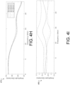
- FIG. 4H illustrates example power spectral densities from FIG. 4G , averaged over loudspeakers.
- the calibration filter manager 160 generates a microphone calibration filter as a ratio of a microphone-and-loudspeaker averaged power spectral density to the loudspeaker-averaged power spectral density.
- FIG. 4I illustrates example microphone calibration filters derived from the loudspeaker-averaged power spectral densities in FIG. 4H .
- FIG. 4J illustrates example power spectral densities from FIG. 4G , averaged over microphones.
- FIG. 4K illustrates example loudspeaker calibration filters derived from the microphone-averaged power spectral densities in FIG. 4J .
- FIG. 5 illustrates an example of a generic computer device 500 and a generic mobile computer device 550, which may be used with the techniques described here.
- computing device 500 is intended to represent various forms of digital computers, such as laptops, desktops, workstations, personal digital assistants, servers, blade servers, mainframes, and other appropriate computers.
- Computing device 550 is intended to represent various forms of mobile devices, such as personal digital assistants, cellular telephones, smart phones, and other similar computing devices.
- the components shown here, their connections and relationships, and their functions, are meant to be exemplary only, and are not meant to limit implementations of the inventions described and/or claimed in this document.
- Computing device 500 includes a processor 502, memory 504, a storage device 506, a high-speed interface 508 connecting to memory 504 and high-speed expansion ports 510, and a low speed interface 512 connecting to low speed bus 514 and storage device 506.
- Each of the components 502, 504, 506, 508, 510, and 512 are interconnected using various busses, and may be mounted on a common motherboard or in other manners as appropriate.
- the processor 502 can process instructions for execution within the computing device 500, including instructions stored in the memory 504 or on the storage device 506 to display graphical information for a GUI on an external input/output device, such as display 516 coupled to high speed interface 508.
- multiple processors and/or multiple buses may be used, as appropriate, along with multiple memories and types of memory.
- multiple computing devices 500 may be connected, with each device providing portions of the necessary operations (e.g., as a server bank, a group of blade servers, or a multi-processor system).
- the memory 504 stores information within the computing device 500.
- the memory 504 is a volatile memory unit or units.
- the memory 504 is a non-volatile memory unit or units.
- the memory 504 may also be another form of computer-readable medium, such as a magnetic or optical disk.
- the high speed controller 508 manages bandwidth-intensive operations for the computing device 500, while the low speed controller 512 manages lower bandwidth-intensive operations.
- the high-speed controller 508 is coupled to memory 504, display 516 (e.g., through a graphics processor or accelerator), and to high-speed expansion ports 510, which may accept various expansion cards (not shown).
- low-speed controller 512 is coupled to storage device 506 and low-speed expansion port 514.
- the low-speed expansion port which may include various communication ports (e.g., USB, Bluetooth, Ethernet, wireless Ethernet) may be coupled to one or more input/output devices, such as a keyboard, a pointing device, a scanner, or a networking device such as a switch or router, e.g., through a network adapter.
- input/output devices such as a keyboard, a pointing device, a scanner, or a networking device such as a switch or router, e.g., through a network adapter.
- the computing device 500 may be implemented in a number of different forms, as shown in the figure. For example, it may be implemented as a standard server 520, or multiple times in a group of such servers. It may also be implemented as part of a rack server system 524. In addition, it may be implemented in a personal computer such as a laptop computer 522. Alternatively, components from computing device 500 may be combined with other components in a mobile device (not shown), such as device 550. Each of such devices may contain one or more of computing device 500, 550, and an entire system may be made up of multiple computing devices 500, 550 communicating with each other.
- Computing device 550 includes a processor 552, memory 564, an input/output device such as a display 554, a communication interface 566, and a transceiver 568, among other components.
- the device 550 may also be provided with a storage device, such as a microdrive or other device, to provide additional storage.
- a storage device such as a microdrive or other device, to provide additional storage.
- Each of the components 550, 552, 564, 554, 566, and 568, are interconnected using various buses, and several of the components may be mounted on a common motherboard or in other manners as appropriate.
- the processor 552 can execute instructions within the computing device 450, including instructions stored in the memory 564.
- the processor may be implemented as a chipset of chips that include separate and multiple analog and digital processors.
- the processor may provide, for example, for coordination of the other components of the device 550, such as control of user interfaces, applications run by device 550, and wireless communication by device 550.
- Processor 552 may communicate with a user through control interface 558 and display interface 556 coupled to a display 554.
- the display 554 may be, for example, a TFT LCD (Thin-Film-Transistor Liquid Crystal Display) or an OLED (Organic Light Emitting Diode) display, or other appropriate display technology.
- the display interface 556 may comprise appropriate circuitry for driving the display 554 to present graphical and other information to a user.
- the control interface 558 may receive commands from a user and convert them for submission to the processor 552.
- an external interface 562 may be provided in communication with processor 552, so as to enable near area communication of device 550 with other devices.
- External interface 562 may provide, for example, for wired communication in some implementations, or for wireless communication in other implementations, and multiple interfaces may also be used.
- the memory 564 stores information within the computing device 550.
- the memory 564 can be implemented as one or more of a computer-readable medium or media, a volatile memory unit or units, or a non-volatile memory unit or units.
- Expansion memory 574 may also be provided and connected to device 550 through expansion interface 572, which may include, for example, a SIMM (Single In Line Memory Module) card interface.
- SIMM Single In Line Memory Module
- expansion memory 574 may provide extra storage space for device 550, or may also store applications or other information for device 550.
- expansion memory 574 may include instructions to carry out or supplement the processes described above, and may include secure information also.
- expansion memory 574 may be provided as a security module for device 550, and may be programmed with instructions that permit secure use of device 550.
- secure applications may be provided via the SIMM cards, along with additional information, such as placing identifying information on the SIMM card in a non-hackable manner.
- the memory may include, for example, flash memory and/or NVRAM memory, as discussed below.
- a computer program product is tangibly embodied in an information carrier.
- the computer program product contains instructions that, when executed, perform one or more methods, such as those described above.
- the information carrier is a computer- or machine-readable medium, such as the memory 564, expansion memory 574, or memory on processor 552, that may be received, for example, over transceiver 568 or external interface 562.
- Device 550 may communicate wirelessly through communication interface 566, which may include digital signal processing circuitry where necessary. Communication interface 566 may provide for communications under various modes or protocols, such as GSM voice calls, SMS, EMS, or MMS messaging, CDMA, TDMA, PDC, WCDMA, CDMA2000, or GPRS, among others. Such communication may occur, for example, through radio-frequency transceiver 568. In addition, short-range communication may occur, such as using a Bluetooth, WiFi, or other such transceiver (not shown). In addition, GPS (Global Positioning System) receiver module 570 may provide additional navigation- and location-related wireless data to device 550, which may be used as appropriate by applications running on device 550.
- GPS Global Positioning System
- Device 550 may also communicate audibly using audio codec 560, which may receive spoken information from a user and convert it to usable digital information. Audio codec 560 may likewise generate audible sound for a user, such as through a speaker, e.g., in a handset of device 550. Such sound may include sound from voice telephone calls, may include recorded sound (e.g., voice messages, music files, etc.) and may also include sound generated by applications operating on device 550.
- Audio codec 560 may receive spoken information from a user and convert it to usable digital information. Audio codec 560 may likewise generate audible sound for a user, such as through a speaker, e.g., in a handset of device 550. Such sound may include sound from voice telephone calls, may include recorded sound (e.g., voice messages, music files, etc.) and may also include sound generated by applications operating on device 550.
- the computing device 550 may be implemented in a number of different forms, as shown in the figure. For example, it may be implemented as a cellular telephone 580. It may also be implemented as part of a smart phone 582, personal digital assistant, or other similar mobile device.
- implementations of the systems and techniques described here can be realized in digital electronic circuitry, integrated circuitry, specially designed ASICs (application specific integrated circuits), computer hardware, firmware, software, and/or combinations thereof.
- ASICs application specific integrated circuits
- These various implementations can include implementation in one or more computer programs that are executable and/or interpretable on a programmable system including at least one programmable processor, which may be special or general purpose, coupled to receive data and instructions from, and to transmit data and instructions to, a storage system, at least one input device, and at least one output device.
- the systems and techniques described here can be implemented on a computer having a display device (e.g., a CRT (cathode ray tube) or LCD (liquid crystal display) monitor) for displaying information to the user and a keyboard and a pointing device (e.g., a mouse or a trackball) by which the user can provide input to the computer.
- a display device e.g., a CRT (cathode ray tube) or LCD (liquid crystal display) monitor
- a keyboard and a pointing device e.g., a mouse or a trackball
- Other kinds of devices can be used to provide for interaction with a user as well; for example, feedback provided to the user can be any form of sensory feedback (e.g., visual feedback, auditory feedback, or tactile feedback); and input from the user can be received in any form, including acoustic, speech, or tactile input.
- the systems and techniques described here can be implemented in a computing system that includes a back end component (e.g., as a data server), or that includes a middleware component (e.g., an application server), or that includes a front end component (e.g., a client computer having a graphical user interface or a Web browser through which a user can interact with an implementation of the systems and techniques described here), or any combination of such back end, middleware, or front end components.
- the components of the system can be interconnected by any form or medium of digital data communication (e.g., a communication network). Examples of communication networks include a local area network ("LAN”), a wide area network (“WAN”), and the Internet.
- LAN local area network
- WAN wide area network
- the Internet the global information network
- the computing system can include clients and servers.
- a client and server are generally remote from each other and typically interact through a communication network.
- the relationship of client and server arises by virtue of computer programs running on the respective computers and having a client-server relationship to each other.
- the memory 126 can be any type of memory such as a random-access memory, a disk drive memory, flash memory, and/or so forth.
- the memory 126 can be implemented as more than one memory component (e.g., more than one RAM component or disk drive memory) associated with the components of the compression computer 120.
- the memory 126 can be a database memory.
- the memory 126 can be, or can include, a non-local memory.
- the memory 126 can be, or can include, a memory shared by multiple devices (not shown).
- the memory 126 can be associated with a server device (not shown) within a network and configured to serve the components of the compression computer 120.
- the components (e.g., modules, processing units 124) of the compression computer 120 can be configured to operate based on one or more platforms (e.g., one or more similar or different platforms) that can include one or more types of hardware, software, firmware, operating systems, runtime libraries, and/or so forth.
- the components of the compression computer 120 can be configured to operate within a cluster of devices (e.g., a server farm). In such an implementation, the functionality and processing of the components of the compression computer 120 can be distributed to several devices of the cluster of devices.
- the components of the computer 120 can be, or can include, any type of hardware and/or software configured to process attributes.
- one or more portions of the components shown in the components of the computer 120 in FIG. 1 can be, or can include, a hardware-based module (e.g., a digital signal processor (DSP), a field programmable gate array (FPGA), a memory), a firmware module, and/or a software-based module (e.g., a module of computer code, a set of computer-readable instructions that can be executed at a computer).
- DSP digital signal processor
- FPGA field programmable gate array
- a memory e.g., a firmware module, and/or a software-based module (e.g., a module of computer code, a set of computer-readable instructions that can be executed at a computer).
- a software-based module e.g., a module of computer code, a set of computer-readable instructions that can be executed at a computer.
- the components of the computer 120 can be configured to operate within, for example, a data center (e.g., a cloud computing environment), a computer system, one or more server/host devices, and/or so forth.
- the components of the computer 120 can be configured to operate within a network.
- the components of the computer 120 can be configured to function within various types of network environments that can include one or more devices and/or one or more server devices.
- a network can be, or can include, a local area network (LAN), a wide area network (WAN), and/or so forth.
- the network can be, or can include, a wireless network and/or wireless network implemented using, for example, gateway devices, bridges, switches, and/or so forth.
- the network can include one or more segments and/or can have portions based on various protocols such as Internet Protocol (IP) and/or a proprietary protocol.
- IP Internet Protocol
- the network can include at least a portion of the Internet.
- one or more of the components of the computer 120 can be, or can include, processors configured to process instructions stored in a memory.
- the depth image manager 130 (and/or a portion thereof), the viewpoint manager 140 (and/or a portion thereof), the ray casting manager 150 (and/or a portion thereof), the SDV manager 160 (and/or a portion thereof), the aggregation manager 170 (and/or a portion thereof), the root-finding manager 180 (and/or a portion thereof), and the depth image generation manager 190 (and/or a portion thereof) can be a combination of a processor and a memory configured to execute instructions related to a process to implement one or more functions.
Landscapes
- Health & Medical Sciences (AREA)
- Otolaryngology (AREA)
- Physics & Mathematics (AREA)
- Engineering & Computer Science (AREA)
- Acoustics & Sound (AREA)
- Signal Processing (AREA)
- General Health & Medical Sciences (AREA)
- Circuit For Audible Band Transducer (AREA)
- Stereophonic System (AREA)
Claims (15)
- Verfahren, umfassend:Empfangen eines nachhallenden Schallfelds (132) über jedes Mikrofon (172) einer Mikrofonanordnung basierend auf einem Audiosignal, das von jedem Lautsprecher (174) einer Lautsprecheranordnung erzeugt wird;Erzeugen, für jedes Mikrofon (172) der Mikrofonanordnung und jeden Lautsprecher (174) der Lautsprecheranordnung, einer jeweiligen Leistungsspektraldichte (154) für dieses Mikrofon (172) und diesen Lautsprecher (174) basierend auf dem jeweiligen nachhallenden Schallfeld (132), das von diesem Lautsprecher (174) erzeugt und an diesem Mikrofon (172) empfangen wird;Erzeugen, für jedes Mikrofon (172) der Mikrofonanordnung, eines jeweiligen Kalibrierungsfilters (162) für dieses Mikrofon (172) als Verhältnis der Leistungsspektraldichte (154), die über die Lautsprecheranordnung und die Mikrofonanordnung gemittelt wird, und einer Leistungsspektraldichte (154) für dieses Mikrofon (172), die über die Lautsprecheranordnung gemittelt wird; undAufzeichnen eines akustischen Signals von einem Benutzer (182) durch die Mikrofonanordnung unter Verwendung des jeweiligen Kalibrierungsfilters (162), der für jedes Mikrofon (172) der Mikrofonanordnung erzeugt wird, wobei jedes Mikrofon (172) der Mikrofonanordnung unter Verwendung des jeweiligen Kalibrierungsfilters (162) im Wesentlichen dasselbe Spektrum des akustischen Signals aufzeichnet.
- Verfahren nach Anspruch 1, wobei das Erzeugen der jeweiligen Leistungsspektraldichte (154) für jedes Mikrofon (172) der Mikrofonanordnung und jeden Lautsprecher (174) der Lautsprecheranordnung Folgendes beinhaltet:
Erzeugen einer jeweiligen Impulsantwortfunktion für dieses Mikrofon (172) und diesen Lautsprecher (174) basierend auf dem jeweiligen nachhallenden Schallfeld (132), das von diesem Lautsprecher (174) erzeugt und an diesem Mikrofon (172) empfangen wird. - Verfahren nach Anspruch 2, wobei das Erzeugen der jeweiligen Leistungsspektraldichte (154) für jedes Mikrofon (172) der Mikrofonanordnung und jeden Lautsprecher (174) der Lautsprecheranordnung ferner Folgendes beinhaltet:Durchführen einer Autokorrelation der jeweiligen Impulsantwortfunktion für dieses Mikrofon (172) und diesen Lautsprecher (174), um eine autokorrelierte Impulsantwortfunktion zu produzieren; undDurchführen einer Transformation in den Frequenzraum an der autokorrelierten Impulsantwortfunktion, um die Leistungsspektraldichte (154) für dieses Mikrofon (172) und diesen Lautsprecher (174) zu produzieren.
- Verfahren nach Anspruch 3, wobei das Durchführen der Transformation in den Frequenzraum an der autokorrelierten Impulsantwortfunktion Folgendes beinhaltet:Erzeugen einer Fensterfunktion, die innerhalb eines angegebenen Zeitintervalls gleich einer Konstanten und außerhalb des angegebenen Zeitintervalls gleich Null ist; undDurchführen einer Fourier-Transformationsoperation an einem Produkt der Fensterfunktion und der autokorrelierten Impulsantwortfunktion.
- Verfahren nach Anspruch 2, das ferner vor dem Erzeugen der jeweiligen Impulsantwortfunktion Folgendes umfasst:
Erzeugen eines gesweepten Sinus-Chirp-Signals als Audiosignal an diesem Lautsprecher (174), das Frequenzen zwischen einer ersten Frequenz und einer zweiten Frequenz aufweist, wobei das gesweepte Sinus-Chirp-Signal an diesem Mikrofon (172) empfangen wird. - Verfahren nach Anspruch 2, wobei das Erzeugen der jeweiligen Impulsantwortfunktion Folgendes beinhaltet:
für jedes Mikrofon (172) der Mikrofonanordnung und jeden Lautsprecher (174) der Lautsprecheranordnung:Messen einer Rohimpulsantwortfunktion, die diesem Mikrofon (172) und diesem Lautsprecher (174) entspricht; undErzeugen einer zeitabhängigen Energiemetrik, die dieser Rohimpulsantwortfunktion zugeordnet ist;Erzeugen eines Normalisierungsfaktors basierend auf einem Mittelwert der jeweiligen zeitabhängigen Energiemetriken, die jedem Mikrofon (172) der Mikrofonanordnung und jedem Lautsprecher (174) der Lautsprecheranordnung zugeordnet sind, über die Mikrofonanordnung und die Lautsprecheranordnung; undDividieren der Rohimpulsantwortfunktion, die jedem Mikrofon (172) der Mikrofonanordnung und jedem Lautsprecher (174) der Lautsprecheranordnung entspricht, durch den Normalisierungsfaktor, um eine abklingnormalisierte Impulsantwortfunktion zu produzieren, die diesem Mikrofon (172) und diesem Lautsprecher entspricht. - Verfahren nach Anspruch 6, wobei das Erzeugen der zeitabhängigen Energiemetrik, die der jeweiligen Rohimpulsantwortfunktion zugeordnet ist, die jedem Mikrofon (172) der Mikrofonanordnung und jedem Lautsprecher (174) der Lautsprecheranordnung entspricht, Folgendes beinhaltet:Erzeugen einer ersten Potenz eines Absolutwerts der jeweiligen Rohimpulsantwortfunktion, die diesem Mikrofon (172) und diesem Lautsprecher (174) entspricht; undDurchführen einer Glättungsoperation an der Potenz des Absolutwerts der jeweiligen Rohimpulsantwortfunktion, um die zeitabhängige Energiemetrik zu produzieren, die der jeweiligen Rohimpulsantwortfunktion zugeordnet ist, die diesem Mikrofon (172) und diesem Lautsprecher (174) entspricht.
- Verfahren nach Anspruch 7, wobei die Durchführung der Glättungsoperation Folgendes beinhaltet:
Erzeugen eines gleitenden Mittelwerts der Potenz des Absolutwerts der jeweiligen Rohimpulsantwortfunktion über einen angegebenen Zeitraum. - Verfahren nach Anspruch 7, wobei das Erzeugen des Normalisierungsfaktors Folgendes beinhaltet:
Erzeugen einer zweiten Potenz der zeitabhängigen Energiemetrik, die der jeweiligen Rohimpulsantwortfunktion zugeordnet ist, die jedem Mikrofon (172) der Mikrofonanordnung und jedem Lautsprecher (174) der Lautsprecheranordnung entspricht, wobei die zweite Potenz eine Inverse der ersten Potenz ist. - Verfahren nach Anspruch 6, wobei das Erzeugen der jeweiligen Impulsantwortfunktion Folgendes beinhaltet:
Erlangen eines Untersegments der abklingnormalisierten Impulsantwortfunktion, die diesem Mikrofon (172) und diesem Lautsprecher (174) entspricht, als jeweilige Impulsantwortfunktion, die jedem Mikrofon (172) der Mikrofonanordnung und jedem Lautsprecher (174) der Lautsprecheranordnung entspricht, wobei das Untersegment zu einem ersten Zeitpunkt beginnt und zu einem zweiten Zeitpunkt endet. - Verfahren nach Anspruch 10, wobei der erste Zeitpunkt auf einer von einem Echo des nachhallenden Schallfelds zurückgelegten Mindestdistanz basiert.
- Verfahren nach Anspruch 10, wobei der zweite Zeitpunkt auf einer Schätzung einer Zeitspanne basiert, die benötigt wird, bis die jeweilige Rohimpulsantwortfunktion auf ein Grundrauschen abklingt, das der Messung der Rohimpulsantwortfunktion zugeordnet ist.
- Verfahren, umfassend:Empfangen eines nachhallenden Schallfelds (132) über jedes Mikrofon (172) einer Mikrofonanordnung basierend auf einem Audiosignal, das von jedem Lautsprecher (174) einer Lautsprecheranordnung erzeugt wird;Erzeugen, für jedes Mikrofon (172) der Mikrofonanordnung und jeden Lautsprecher (174) der Lautsprecheranordnung, einer jeweiligen Leistungsspektraldichte (154) für dieses Mikrofon (172) und diesen Lautsprecher (174) basierend auf dem jeweiligen nachhallenden Schallfeld (132), das von diesem Lautsprecher (172) erzeugt und an diesem Mikrofon (174) empfangen wird;Erzeugen, für jeden Lautsprecher (174) der Lautsprecheranordnung, eines jeweiligen Kalibrierungsfilters (164) für diesen Lautsprecher (174) als Verhältnis der über die Lautsprecheranordnung gemittelten spektralen Leistungsdichte (154) und einer über die Mikrofonanordnung gemittelten spektralen Leistungsdichte (154) für diesen Lautsprecher (174); undErzeugen eines akustischen Signals durch die Lautsprecheranordnung unter Verwendung des jeweiligen Kalibrierungsfilters (164), der für jeden Lautsprecher (174) der Lautsprecheranordnung erzeugt wird, wobei jeder Lautsprecher (174) der Lautsprecheranordnung unter Verwendung des jeweiligen Kalibrierungsfilters (164) im Wesentlichen das gleiche Spektrum des akustischen Signals als Reaktion auf den gleichen Ausgabestimulus produziert.
- Computerprogrammprodukt, das ein nichttransitives Speichermedium umfasst, wobei das Computerprogrammprodukt Code beinhaltet, der bei Ausführung durch die Verarbeitungsschaltkreise einer Rechenvorrichtung die Verarbeitungsschaltkreise veranlasst, ein Verfahren durchzuführen, wobei das Verfahren Folgendes umfasst:Empfangen eines nachhallenden Schallfelds (132) über jedes Mikrofon (172) einer Mikrofonanordnung basierend auf einem Audiosignal, das von jedem Lautsprecher (174) einer Lautsprecheranordnung erzeugt wird;Erzeugen, für jedes Mikrofon (172) der Mikrofonanordnung und jeden Lautsprecher (174) der Lautsprecheranordnung, einer jeweiligen Leistungsspektraldichte (154) für dieses Mikrofon (172) und diesen Lautsprecher (174) basierend auf dem jeweiligen nachhallenden Schallfeld (132), das von diesem Lautsprecher (174) erzeugt und an diesem Mikrofon (172) empfangen wird;Erzeugen, für jedes Mikrofon (172) der Mikrofonanordnung, eines jeweiligen Kalibrierungsfilters (162) für dieses Mikrofon (172) als Verhältnis der Leistungsspektraldichte (154), die über die Lautsprecheranordnung und die Mikrofonanordnung gemittelt wird, und einer Leistungsspektraldichte (154) für dieses Mikrofon (172), die über die Lautsprecheranordnung gemittelt wird; undAufzeichnen eines akustischen Signals von einem Benutzer (182) durch die Mikrofonanordnung unter Verwendung des jeweiligen Kalibrierungsfilters (162), der für jedes Mikrofon (172) der Mikrofonanordnung erzeugt wird, wobei jedes Mikrofon (172) der Mikrofonanordnung unter Verwendung des jeweiligen Kalibrierungsfilters (162) im Wesentlichen dasselbe Spektrum des akustischen Signals aufzeichnet.
- Elektronische Vorrichtung, wobei die elektronische Vorrichtung Folgendes umfasst:einen Speicher; undSteuerschaltkreise, die mit dem Speicher gekoppelt sind, wobei die Steuerschaltkreise zu Folgendem konfiguriert sind:Empfangen eines nachhallenden Schallfelds (132) über jedes Mikrofon (172) einer Mikrofonanordnung basierend auf einem Audiosignal, das von jedem Lautsprecher (174) einer Lautsprecheranordnung erzeugt wird;Erzeugen, für jedes Mikrofon (172) der Mikrofonanordnung und jeden Lautsprecher (174) der Lautsprecheranordnung, einer jeweiligen Leistungsspektraldichte (154) für dieses Mikrofon (172) und diesen Lautsprecher (174) basierend auf dem jeweiligen nachhallenden Schallfeld (132), das von diesem Lautsprecher (174) erzeugt und an diesem Mikrofon (172) empfangen wird;Erzeugen, für jedes Mikrofon (172) der Mikrofonanordnung, eines jeweiligen Kalibrierungsfilters (162) für dieses Mikrofon (172) als Verhältnis der Leistungsspektraldichte (154), die über die Lautsprecheranordnung und die Mikrofonanordnung gemittelt wird, und einer Leistungsspektraldichte (154) für dieses Mikrofon (172), die über die Lautsprecheranordnung gemittelt wird; undAufzeichnen eines akustischen Signals von einem Benutzer (182) durch die Mikrofonanordnung unter Verwendung des jeweiligen Kalibrierungsfilters (162), der für jedes Mikrofon (172) der Mikrofonanordnung erzeugt wird, wobei jedes Mikrofon (172) der Mikrofonanordnung unter Verwendung des jeweiligen Kalibrierungsfilters (162) im Wesentlichen dasselbe Spektrum des akustischen Signals aufzeichnet.
Applications Claiming Priority (1)
| Application Number | Priority Date | Filing Date | Title |
|---|---|---|---|
| PCT/US2020/070723 WO2022093295A1 (en) | 2020-10-30 | 2020-10-30 | Automatic calibration of microphone array for telepresence conferencing |
Publications (2)
| Publication Number | Publication Date |
|---|---|
| EP4238317A1 EP4238317A1 (de) | 2023-09-06 |
| EP4238317B1 true EP4238317B1 (de) | 2024-08-28 |
Family
ID=73646612
Family Applications (1)
| Application Number | Title | Priority Date | Filing Date |
|---|---|---|---|
| EP20816861.7A Active EP4238317B1 (de) | 2020-10-30 | 2020-10-30 | Automatische kalibrierung einer mikrofonanordnung für telepräsenzkonferenzen |
Country Status (6)
| Country | Link |
|---|---|
| US (1) | US12549916B2 (de) |
| EP (1) | EP4238317B1 (de) |
| JP (2) | JP7434668B2 (de) |
| KR (1) | KR102844321B1 (de) |
| CN (1) | CN116472724B (de) |
| WO (1) | WO2022093295A1 (de) |
Citations (1)
| Publication number | Priority date | Publication date | Assignee | Title |
|---|---|---|---|---|
| US20210092548A1 (en) * | 2019-09-19 | 2021-03-25 | Wave Sciences, LLC | Spatial audio array processing system and method |
Family Cites Families (16)
| Publication number | Priority date | Publication date | Assignee | Title |
|---|---|---|---|---|
| US7158643B2 (en) | 2000-04-21 | 2007-01-02 | Keyhold Engineering, Inc. | Auto-calibrating surround system |
| WO2002001915A2 (en) | 2000-06-30 | 2002-01-03 | Koninklijke Philips Electronics N.V. | Device and method for calibration of a microphone |
| EP1715669A1 (de) * | 2005-04-19 | 2006-10-25 | Ecole Polytechnique Federale De Lausanne (Epfl) | Ein Verfahren zum Unterdrücken eines Echos in einem Audiosignal |
| US7813923B2 (en) | 2005-10-14 | 2010-10-12 | Microsoft Corporation | Calibration based beamforming, non-linear adaptive filtering, and multi-sensor headset |
| JP2008164747A (ja) | 2006-12-27 | 2008-07-17 | Toyota Motor Corp | 音声認識ロボット |
| KR100930835B1 (ko) * | 2008-01-29 | 2009-12-10 | 한국과학기술원 | 음향 재생 장치 |
| JP5197458B2 (ja) | 2009-03-25 | 2013-05-15 | 株式会社東芝 | 受音信号処理装置、方法およびプログラム |
| US9241228B2 (en) | 2011-12-29 | 2016-01-19 | Stmicroelectronics Asia Pacific Pte. Ltd. | Adaptive self-calibration of small microphone array by soundfield approximation and frequency domain magnitude equalization |
| EP2829081B1 (de) | 2012-03-23 | 2015-12-09 | Dolby Laboratories Licensing Corporation | Selbsttest einer konferenzvorrichtung |
| US10708701B2 (en) * | 2015-10-28 | 2020-07-07 | Music Tribe Global Brands Ltd. | Sound level estimation |
| WO2017075601A1 (en) * | 2015-10-30 | 2017-05-04 | The Johns Hopkins University | Programmable electronic stethoscope devices, algorithms, systems, and methods |
| US9763018B1 (en) * | 2016-04-12 | 2017-09-12 | Sonos, Inc. | Calibration of audio playback devices |
| US10080088B1 (en) * | 2016-11-10 | 2018-09-18 | Amazon Technologies, Inc. | Sound zone reproduction system |
| US11516614B2 (en) * | 2018-04-13 | 2022-11-29 | Huawei Technologies Co., Ltd. | Generating sound zones using variable span filters |
| US11217264B1 (en) * | 2020-03-11 | 2022-01-04 | Meta Platforms, Inc. | Detection and removal of wind noise |
| US11624804B2 (en) * | 2020-10-08 | 2023-04-11 | Nokia Technologies Oy | System and method for location determination utilizing direct path information |
-
2020
- 2020-10-30 CN CN202080106843.3A patent/CN116472724B/zh active Active
- 2020-10-30 US US18/249,924 patent/US12549916B2/en active Active
- 2020-10-30 EP EP20816861.7A patent/EP4238317B1/de active Active
- 2020-10-30 KR KR1020237017702A patent/KR102844321B1/ko active Active
- 2020-10-30 WO PCT/US2020/070723 patent/WO2022093295A1/en not_active Ceased
- 2020-10-30 JP JP2023526352A patent/JP7434668B2/ja active Active
-
2024
- 2024-02-07 JP JP2024017209A patent/JP7724317B2/ja active Active
Patent Citations (1)
| Publication number | Priority date | Publication date | Assignee | Title |
|---|---|---|---|---|
| US20210092548A1 (en) * | 2019-09-19 | 2021-03-25 | Wave Sciences, LLC | Spatial audio array processing system and method |
Also Published As
| Publication number | Publication date |
|---|---|
| US20240007810A1 (en) | 2024-01-04 |
| CN116472724B (zh) | 2025-11-18 |
| EP4238317A1 (de) | 2023-09-06 |
| KR102844321B1 (ko) | 2025-08-08 |
| CN116472724A (zh) | 2023-07-21 |
| KR20230096050A (ko) | 2023-06-29 |
| WO2022093295A1 (en) | 2022-05-05 |
| US12549916B2 (en) | 2026-02-10 |
| JP2023546257A (ja) | 2023-11-01 |
| JP7724317B2 (ja) | 2025-08-15 |
| JP2024063009A (ja) | 2024-05-10 |
| JP7434668B2 (ja) | 2024-02-20 |
Similar Documents
| Publication | Publication Date | Title |
|---|---|---|
| US10978088B2 (en) | Methods and systems for improved measurement, entity and parameter estimation, and path propagation effect measurement and mitigation in source signal separation | |
| US10939225B2 (en) | Calibrating listening devices | |
| US9439019B2 (en) | Sound signal processing method and apparatus | |
| KR102118411B1 (ko) | 원신호 분리 시스템 및 방법 | |
| US8693713B2 (en) | Virtual audio environment for multidimensional conferencing | |
| US20180376273A1 (en) | System and method for determining audio context in augmented-reality applications | |
| EP3262853B1 (de) | Computerprogramm und verfahren zur bestimmung einer personalisierten kopfbezogenen übertragungsfunktion und interaurale zeitdifferenzfunktion | |
| EP4256816A1 (de) | Pervasive akustische abbildung | |
| US20250273224A1 (en) | Data sequence generation | |
| EP3129795A1 (de) | Verfahren und systeme zur verbesserten messung, einheit und parameterschätzung sowie messung und minderung eines wegausbreitungseffekts bei einer quellensignaltrennung | |
| US11115773B1 (en) | Audio system and method of generating an HRTF map | |
| EP4238317B1 (de) | Automatische kalibrierung einer mikrofonanordnung für telepräsenzkonferenzen | |
| US11877143B2 (en) | Parameterized modeling of coherent and incoherent sound | |
| US10506192B2 (en) | Gesture-activated remote control | |
| CN113678473B (zh) | 三维音频源空间化 | |
| EP3625975B1 (de) | Inkohärente idempotente ambisonics-darstellung | |
| Meyer-Kahlen et al. | Parametric late reverberation from broadband directional estimates | |
| US12395809B2 (en) | Audibility at user location through mutual device audibility | |
| Wang et al. | Method of estimating three-dimensional direction-of-arrival based on monaural modulation spectrum | |
| JP7815249B2 (ja) | パーベイシブ音響マッピング | |
| US12538087B2 (en) | Efficient modeling of filters | |
| Manamperi | Parameterisation, Localisation, and Enhancement of Spatial Soundfield from Drone On-Board Microphones |
Legal Events
| Date | Code | Title | Description |
|---|---|---|---|
| STAA | Information on the status of an ep patent application or granted ep patent |
Free format text: STATUS: UNKNOWN |
|
| STAA | Information on the status of an ep patent application or granted ep patent |
Free format text: STATUS: THE INTERNATIONAL PUBLICATION HAS BEEN MADE |
|
| PUAI | Public reference made under article 153(3) epc to a published international application that has entered the european phase |
Free format text: ORIGINAL CODE: 0009012 |
|
| STAA | Information on the status of an ep patent application or granted ep patent |
Free format text: STATUS: REQUEST FOR EXAMINATION WAS MADE |
|
| 17P | Request for examination filed |
Effective date: 20230428 |
|
| AK | Designated contracting states |
Kind code of ref document: A1 Designated state(s): AL AT BE BG CH CY CZ DE DK EE ES FI FR GB GR HR HU IE IS IT LI LT LU LV MC MK MT NL NO PL PT RO RS SE SI SK SM TR |
|
| DAV | Request for validation of the european patent (deleted) | ||
| DAX | Request for extension of the european patent (deleted) | ||
| GRAP | Despatch of communication of intention to grant a patent |
Free format text: ORIGINAL CODE: EPIDOSNIGR1 |
|
| STAA | Information on the status of an ep patent application or granted ep patent |
Free format text: STATUS: GRANT OF PATENT IS INTENDED |
|
| INTG | Intention to grant announced |
Effective date: 20240320 |
|
| GRAS | Grant fee paid |
Free format text: ORIGINAL CODE: EPIDOSNIGR3 |
|
| GRAA | (expected) grant |
Free format text: ORIGINAL CODE: 0009210 |
|
| STAA | Information on the status of an ep patent application or granted ep patent |
Free format text: STATUS: THE PATENT HAS BEEN GRANTED |
|
| AK | Designated contracting states |
Kind code of ref document: B1 Designated state(s): AL AT BE BG CH CY CZ DE DK EE ES FI FR GB GR HR HU IE IS IT LI LT LU LV MC MK MT NL NO PL PT RO RS SE SI SK SM TR |
|
| P01 | Opt-out of the competence of the unified patent court (upc) registered |
Free format text: CASE NUMBER: APP_42685/2024 Effective date: 20240719 |
|
| REG | Reference to a national code |
Ref country code: CH Ref legal event code: EP |
|
| REG | Reference to a national code |
Ref country code: DE Ref legal event code: R096 Ref document number: 602020036786 Country of ref document: DE |
|
| REG | Reference to a national code |
Ref country code: IE Ref legal event code: FG4D |
|
| REG | Reference to a national code |
Ref country code: LT Ref legal event code: MG9D |
|
| PG25 | Lapsed in a contracting state [announced via postgrant information from national office to epo] |
Ref country code: NO Free format text: LAPSE BECAUSE OF FAILURE TO SUBMIT A TRANSLATION OF THE DESCRIPTION OR TO PAY THE FEE WITHIN THE PRESCRIBED TIME-LIMIT Effective date: 20241128 |
|
| REG | Reference to a national code |
Ref country code: AT Ref legal event code: MK05 Ref document number: 1719230 Country of ref document: AT Kind code of ref document: T Effective date: 20240828 |
|
| PG25 | Lapsed in a contracting state [announced via postgrant information from national office to epo] |
Ref country code: PL Free format text: LAPSE BECAUSE OF FAILURE TO SUBMIT A TRANSLATION OF THE DESCRIPTION OR TO PAY THE FEE WITHIN THE PRESCRIBED TIME-LIMIT Effective date: 20240828 Ref country code: GR Free format text: LAPSE BECAUSE OF FAILURE TO SUBMIT A TRANSLATION OF THE DESCRIPTION OR TO PAY THE FEE WITHIN THE PRESCRIBED TIME-LIMIT Effective date: 20241129 Ref country code: FI Free format text: LAPSE BECAUSE OF FAILURE TO SUBMIT A TRANSLATION OF THE DESCRIPTION OR TO PAY THE FEE WITHIN THE PRESCRIBED TIME-LIMIT Effective date: 20240828 Ref country code: PT Free format text: LAPSE BECAUSE OF FAILURE TO SUBMIT A TRANSLATION OF THE DESCRIPTION OR TO PAY THE FEE WITHIN THE PRESCRIBED TIME-LIMIT Effective date: 20241230 Ref country code: NL Free format text: LAPSE BECAUSE OF FAILURE TO SUBMIT A TRANSLATION OF THE DESCRIPTION OR TO PAY THE FEE WITHIN THE PRESCRIBED TIME-LIMIT Effective date: 20240828 |
|
| PG25 | Lapsed in a contracting state [announced via postgrant information from national office to epo] |
Ref country code: BG Free format text: LAPSE BECAUSE OF FAILURE TO SUBMIT A TRANSLATION OF THE DESCRIPTION OR TO PAY THE FEE WITHIN THE PRESCRIBED TIME-LIMIT Effective date: 20240828 |
|
| PG25 | Lapsed in a contracting state [announced via postgrant information from national office to epo] |
Ref country code: LV Free format text: LAPSE BECAUSE OF FAILURE TO SUBMIT A TRANSLATION OF THE DESCRIPTION OR TO PAY THE FEE WITHIN THE PRESCRIBED TIME-LIMIT Effective date: 20240828 |
|
| REG | Reference to a national code |
Ref country code: NL Ref legal event code: MP Effective date: 20240828 |
|
| PG25 | Lapsed in a contracting state [announced via postgrant information from national office to epo] |
Ref country code: AT Free format text: LAPSE BECAUSE OF FAILURE TO SUBMIT A TRANSLATION OF THE DESCRIPTION OR TO PAY THE FEE WITHIN THE PRESCRIBED TIME-LIMIT Effective date: 20240828 Ref country code: IS Free format text: LAPSE BECAUSE OF FAILURE TO SUBMIT A TRANSLATION OF THE DESCRIPTION OR TO PAY THE FEE WITHIN THE PRESCRIBED TIME-LIMIT Effective date: 20241228 |
|
| PG25 | Lapsed in a contracting state [announced via postgrant information from national office to epo] |
Ref country code: HR Free format text: LAPSE BECAUSE OF FAILURE TO SUBMIT A TRANSLATION OF THE DESCRIPTION OR TO PAY THE FEE WITHIN THE PRESCRIBED TIME-LIMIT Effective date: 20240828 |
|
| PG25 | Lapsed in a contracting state [announced via postgrant information from national office to epo] |
Ref country code: RS Free format text: LAPSE BECAUSE OF FAILURE TO SUBMIT A TRANSLATION OF THE DESCRIPTION OR TO PAY THE FEE WITHIN THE PRESCRIBED TIME-LIMIT Effective date: 20241128 Ref country code: ES Free format text: LAPSE BECAUSE OF FAILURE TO SUBMIT A TRANSLATION OF THE DESCRIPTION OR TO PAY THE FEE WITHIN THE PRESCRIBED TIME-LIMIT Effective date: 20240828 |
|
| PG25 | Lapsed in a contracting state [announced via postgrant information from national office to epo] |
Ref country code: RS Free format text: LAPSE BECAUSE OF FAILURE TO SUBMIT A TRANSLATION OF THE DESCRIPTION OR TO PAY THE FEE WITHIN THE PRESCRIBED TIME-LIMIT Effective date: 20241128 Ref country code: PT Free format text: LAPSE BECAUSE OF FAILURE TO SUBMIT A TRANSLATION OF THE DESCRIPTION OR TO PAY THE FEE WITHIN THE PRESCRIBED TIME-LIMIT Effective date: 20241230 Ref country code: PL Free format text: LAPSE BECAUSE OF FAILURE TO SUBMIT A TRANSLATION OF THE DESCRIPTION OR TO PAY THE FEE WITHIN THE PRESCRIBED TIME-LIMIT Effective date: 20240828 Ref country code: NO Free format text: LAPSE BECAUSE OF FAILURE TO SUBMIT A TRANSLATION OF THE DESCRIPTION OR TO PAY THE FEE WITHIN THE PRESCRIBED TIME-LIMIT Effective date: 20241128 Ref country code: NL Free format text: LAPSE BECAUSE OF FAILURE TO SUBMIT A TRANSLATION OF THE DESCRIPTION OR TO PAY THE FEE WITHIN THE PRESCRIBED TIME-LIMIT Effective date: 20240828 Ref country code: LV Free format text: LAPSE BECAUSE OF FAILURE TO SUBMIT A TRANSLATION OF THE DESCRIPTION OR TO PAY THE FEE WITHIN THE PRESCRIBED TIME-LIMIT Effective date: 20240828 Ref country code: IS Free format text: LAPSE BECAUSE OF FAILURE TO SUBMIT A TRANSLATION OF THE DESCRIPTION OR TO PAY THE FEE WITHIN THE PRESCRIBED TIME-LIMIT Effective date: 20241228 Ref country code: HR Free format text: LAPSE BECAUSE OF FAILURE TO SUBMIT A TRANSLATION OF THE DESCRIPTION OR TO PAY THE FEE WITHIN THE PRESCRIBED TIME-LIMIT Effective date: 20240828 Ref country code: GR Free format text: LAPSE BECAUSE OF FAILURE TO SUBMIT A TRANSLATION OF THE DESCRIPTION OR TO PAY THE FEE WITHIN THE PRESCRIBED TIME-LIMIT Effective date: 20241129 Ref country code: FI Free format text: LAPSE BECAUSE OF FAILURE TO SUBMIT A TRANSLATION OF THE DESCRIPTION OR TO PAY THE FEE WITHIN THE PRESCRIBED TIME-LIMIT Effective date: 20240828 Ref country code: ES Free format text: LAPSE BECAUSE OF FAILURE TO SUBMIT A TRANSLATION OF THE DESCRIPTION OR TO PAY THE FEE WITHIN THE PRESCRIBED TIME-LIMIT Effective date: 20240828 Ref country code: BG Free format text: LAPSE BECAUSE OF FAILURE TO SUBMIT A TRANSLATION OF THE DESCRIPTION OR TO PAY THE FEE WITHIN THE PRESCRIBED TIME-LIMIT Effective date: 20240828 Ref country code: AT Free format text: LAPSE BECAUSE OF FAILURE TO SUBMIT A TRANSLATION OF THE DESCRIPTION OR TO PAY THE FEE WITHIN THE PRESCRIBED TIME-LIMIT Effective date: 20240828 |
|
| PG25 | Lapsed in a contracting state [announced via postgrant information from national office to epo] |
Ref country code: RO Free format text: LAPSE BECAUSE OF FAILURE TO SUBMIT A TRANSLATION OF THE DESCRIPTION OR TO PAY THE FEE WITHIN THE PRESCRIBED TIME-LIMIT Effective date: 20240828 Ref country code: DK Free format text: LAPSE BECAUSE OF FAILURE TO SUBMIT A TRANSLATION OF THE DESCRIPTION OR TO PAY THE FEE WITHIN THE PRESCRIBED TIME-LIMIT Effective date: 20240828 Ref country code: SM Free format text: LAPSE BECAUSE OF FAILURE TO SUBMIT A TRANSLATION OF THE DESCRIPTION OR TO PAY THE FEE WITHIN THE PRESCRIBED TIME-LIMIT Effective date: 20240828 |
|
| PG25 | Lapsed in a contracting state [announced via postgrant information from national office to epo] |
Ref country code: EE Free format text: LAPSE BECAUSE OF FAILURE TO SUBMIT A TRANSLATION OF THE DESCRIPTION OR TO PAY THE FEE WITHIN THE PRESCRIBED TIME-LIMIT Effective date: 20240828 |
|
| PG25 | Lapsed in a contracting state [announced via postgrant information from national office to epo] |
Ref country code: CZ Free format text: LAPSE BECAUSE OF FAILURE TO SUBMIT A TRANSLATION OF THE DESCRIPTION OR TO PAY THE FEE WITHIN THE PRESCRIBED TIME-LIMIT Effective date: 20240828 |
|
| PG25 | Lapsed in a contracting state [announced via postgrant information from national office to epo] |
Ref country code: IT Free format text: LAPSE BECAUSE OF FAILURE TO SUBMIT A TRANSLATION OF THE DESCRIPTION OR TO PAY THE FEE WITHIN THE PRESCRIBED TIME-LIMIT Effective date: 20240828 Ref country code: SK Free format text: LAPSE BECAUSE OF FAILURE TO SUBMIT A TRANSLATION OF THE DESCRIPTION OR TO PAY THE FEE WITHIN THE PRESCRIBED TIME-LIMIT Effective date: 20240828 |
|
| REG | Reference to a national code |
Ref country code: CH Ref legal event code: PL Ref country code: DE Ref legal event code: R097 Ref document number: 602020036786 Country of ref document: DE |
|
| PLBE | No opposition filed within time limit |
Free format text: ORIGINAL CODE: 0009261 |
|
| STAA | Information on the status of an ep patent application or granted ep patent |
Free format text: STATUS: NO OPPOSITION FILED WITHIN TIME LIMIT |
|
| PG25 | Lapsed in a contracting state [announced via postgrant information from national office to epo] |
Ref country code: MC Free format text: LAPSE BECAUSE OF FAILURE TO SUBMIT A TRANSLATION OF THE DESCRIPTION OR TO PAY THE FEE WITHIN THE PRESCRIBED TIME-LIMIT Effective date: 20240828 |
|
| PG25 | Lapsed in a contracting state [announced via postgrant information from national office to epo] |
Ref country code: LU Free format text: LAPSE BECAUSE OF NON-PAYMENT OF DUE FEES Effective date: 20241030 Ref country code: BE Free format text: LAPSE BECAUSE OF NON-PAYMENT OF DUE FEES Effective date: 20241031 |
|
| PG25 | Lapsed in a contracting state [announced via postgrant information from national office to epo] |
Ref country code: CH Free format text: LAPSE BECAUSE OF NON-PAYMENT OF DUE FEES Effective date: 20241031 |
|
| 26N | No opposition filed |
Effective date: 20250530 |
|
| REG | Reference to a national code |
Ref country code: BE Ref legal event code: MM Effective date: 20241031 |
|
| PG25 | Lapsed in a contracting state [announced via postgrant information from national office to epo] |
Ref country code: SE Free format text: LAPSE BECAUSE OF FAILURE TO SUBMIT A TRANSLATION OF THE DESCRIPTION OR TO PAY THE FEE WITHIN THE PRESCRIBED TIME-LIMIT Effective date: 20240828 |
|
| PG25 | Lapsed in a contracting state [announced via postgrant information from national office to epo] |
Ref country code: IE Free format text: LAPSE BECAUSE OF NON-PAYMENT OF DUE FEES Effective date: 20241030 |
|
| PGFP | Annual fee paid to national office [announced via postgrant information from national office to epo] |
Ref country code: DE Payment date: 20251029 Year of fee payment: 6 |
|
| PGFP | Annual fee paid to national office [announced via postgrant information from national office to epo] |
Ref country code: GB Payment date: 20251027 Year of fee payment: 6 |
|
| PGFP | Annual fee paid to national office [announced via postgrant information from national office to epo] |
Ref country code: FR Payment date: 20251027 Year of fee payment: 6 |