EP4237664B1 - Element de carenage pour entourer un obstacle dans un ecoulement de fluide - Google Patents
Element de carenage pour entourer un obstacle dans un ecoulement de fluide Download PDFInfo
- Publication number
- EP4237664B1 EP4237664B1 EP21805566.3A EP21805566A EP4237664B1 EP 4237664 B1 EP4237664 B1 EP 4237664B1 EP 21805566 A EP21805566 A EP 21805566A EP 4237664 B1 EP4237664 B1 EP 4237664B1
- Authority
- EP
- European Patent Office
- Prior art keywords
- flow
- fairing element
- extrados
- passage
- stator
- Prior art date
- Legal status (The legal status is an assumption and is not a legal conclusion. Google has not performed a legal analysis and makes no representation as to the accuracy of the status listed.)
- Active
Links
Images


Classifications
-
- F—MECHANICAL ENGINEERING; LIGHTING; HEATING; WEAPONS; BLASTING
- F01—MACHINES OR ENGINES IN GENERAL; ENGINE PLANTS IN GENERAL; STEAM ENGINES
- F01D—NON-POSITIVE DISPLACEMENT MACHINES OR ENGINES, e.g. STEAM TURBINES
- F01D5/00—Blades; Blade-carrying members; Heating, heat-insulating, cooling or antivibration means on the blades or the members
- F01D5/12—Blades
- F01D5/14—Form or construction
- F01D5/141—Shape, i.e. outer, aerodynamic form
-
- F—MECHANICAL ENGINEERING; LIGHTING; HEATING; WEAPONS; BLASTING
- F01—MACHINES OR ENGINES IN GENERAL; ENGINE PLANTS IN GENERAL; STEAM ENGINES
- F01D—NON-POSITIVE DISPLACEMENT MACHINES OR ENGINES, e.g. STEAM TURBINES
- F01D25/00—Component parts, details, or accessories, not provided for in, or of interest apart from, other groups
- F01D25/16—Arrangement of bearings; Supporting or mounting bearings in casings
- F01D25/162—Bearing supports
-
- F—MECHANICAL ENGINEERING; LIGHTING; HEATING; WEAPONS; BLASTING
- F01—MACHINES OR ENGINES IN GENERAL; ENGINE PLANTS IN GENERAL; STEAM ENGINES
- F01D—NON-POSITIVE DISPLACEMENT MACHINES OR ENGINES, e.g. STEAM TURBINES
- F01D5/00—Blades; Blade-carrying members; Heating, heat-insulating, cooling or antivibration means on the blades or the members
- F01D5/12—Blades
- F01D5/14—Form or construction
- F01D5/141—Shape, i.e. outer, aerodynamic form
- F01D5/142—Shape, i.e. outer, aerodynamic form of the blades of successive rotor or stator blade-rows
- F01D5/143—Contour of the outer or inner working fluid flow path wall, i.e. shroud or hub contour
-
- F—MECHANICAL ENGINEERING; LIGHTING; HEATING; WEAPONS; BLASTING
- F01—MACHINES OR ENGINES IN GENERAL; ENGINE PLANTS IN GENERAL; STEAM ENGINES
- F01D—NON-POSITIVE DISPLACEMENT MACHINES OR ENGINES, e.g. STEAM TURBINES
- F01D9/00—Stators
- F01D9/02—Nozzles; Nozzle boxes; Stator blades; Guide conduits, e.g. individual nozzles
- F01D9/04—Nozzles; Nozzle boxes; Stator blades; Guide conduits, e.g. individual nozzles forming ring or sector
- F01D9/041—Nozzles; Nozzle boxes; Stator blades; Guide conduits, e.g. individual nozzles forming ring or sector using blades
-
- F—MECHANICAL ENGINEERING; LIGHTING; HEATING; WEAPONS; BLASTING
- F05—INDEXING SCHEMES RELATING TO ENGINES OR PUMPS IN VARIOUS SUBCLASSES OF CLASSES F01-F04
- F05D—INDEXING SCHEME FOR ASPECTS RELATING TO NON-POSITIVE-DISPLACEMENT MACHINES OR ENGINES, GAS-TURBINES OR JET-PROPULSION PLANTS
- F05D2240/00—Components
- F05D2240/10—Stators
- F05D2240/12—Fluid guiding means, e.g. vanes
- F05D2240/124—Fluid guiding means, e.g. vanes related to the suction side of a stator vane
-
- F—MECHANICAL ENGINEERING; LIGHTING; HEATING; WEAPONS; BLASTING
- F05—INDEXING SCHEMES RELATING TO ENGINES OR PUMPS IN VARIOUS SUBCLASSES OF CLASSES F01-F04
- F05D—INDEXING SCHEME FOR ASPECTS RELATING TO NON-POSITIVE-DISPLACEMENT MACHINES OR ENGINES, GAS-TURBINES OR JET-PROPULSION PLANTS
- F05D2260/00—Function
- F05D2260/97—Reducing windage losses
-
- Y—GENERAL TAGGING OF NEW TECHNOLOGICAL DEVELOPMENTS; GENERAL TAGGING OF CROSS-SECTIONAL TECHNOLOGIES SPANNING OVER SEVERAL SECTIONS OF THE IPC; TECHNICAL SUBJECTS COVERED BY FORMER USPC CROSS-REFERENCE ART COLLECTIONS [XRACs] AND DIGESTS
- Y02—TECHNOLOGIES OR APPLICATIONS FOR MITIGATION OR ADAPTATION AGAINST CLIMATE CHANGE
- Y02T—CLIMATE CHANGE MITIGATION TECHNOLOGIES RELATED TO TRANSPORTATION
- Y02T50/00—Aeronautics or air transport
- Y02T50/60—Efficient propulsion technologies, e.g. for aircraft
Definitions
- the present disclosure relates to a shroud element for surrounding an obstacle in a fluid flow, a turbomachine that incorporates such an element, and a method of manufacturing the shroud element.
- This nominal design may be the flow through a free section of a passage, i.e. in the absence of an obstacle.
- the nominal flow may alternatively relate to a passage which is provided with an element useful for the flow, such as an element for modifying a local speed direction of the flow.
- the fairing element has the function of dividing the flow between two sides of the obstacle, and this function of dividing the flow may be combined with that of a useful element which is initially provided in the passage.
- the fairing element may thus have the dual function of guiding the flow on two opposite sides of the obstacle, and of modifying an inclination of the flow.
- This may be the case, in particular, of a stator for straightening the air flow passing through a turbomachine, for example an aircraft engine.
- the obstacle may be a structural support of a part of the turbomachine, a mechanical transmission shaft passing through the flow, a fuel pipe, a fastening bolt, etc.
- a fairing element which is thus arranged in a flow locally disturbs the pressure field within the flow upstream of this fairing element.
- This disturbance of the pressure field can then hinder operation of a rotor which is arranged just before the stator relative to the direction of flow, and consequently degrade the operation of the turbomachine. It can also cause unwanted acoustic emissions, due to the rapid movement of the rotor against the spatial variations of the pressure field which are caused by the fairing element upstream of the flow.
- such a separation distance increases the size and weight of the turbomachine, which is particularly penalizing in the case of an aeronautical turbomachine.
- the document FR 2 019 709 describes a turbomachine stator that includes shroud elements, called struts, that are interposed between adjacent stator blades.
- a suction surface of each strut, or extrados surface is substantially planar and parallel to the direction of airflow from a leading edge of the strut that is oriented upstream of the flow.
- the stator blades are axially staggered between two successive shroud elements and are angularly spaced from each other.
- planar shape of the upstream portion of the extrados surface is only appropriate if the angle of incidence of the flow on the leading edge is constant along the entire leading edge, and if there are no variations in a cross-section or mean radius for the flow passage at the shroud element.
- an object of the present invention is to further reduce flow disturbances which are likely to be caused by the fairing element, compared to the nominal flow design.
- an aim of the invention is to reduce such disturbances which are caused by the fairing element in the pressure field within the fluid upstream of this fairing element.
- Another object of the invention is to reduce a length of the fairing element parallel to the flow, for a given obstacle size, without increasing the flow disturbances which are produced by the fairing element.
- a first aspect of the invention provides a novel fairing element for placement in a fluid flow passage and for surrounding an obstacle passing through the passage such that the fairing element guides the flow of the fluid on two opposite sides of the obstacle.
- the fairing element is designed for nominal values of several flow parameters, including at least a density of the fluid, respective variations of a cross-section and a mean radius of the passage along the flow, a direction of flow in the passage, a velocity value of the flow, and an angle of incidence of the flow relative to the obstacle upstream thereof.
- These nominal flow values may be included in a notice that is provided with the fairing element, regardless of the form or medium of this notice: printed brochure, recording on a data medium such as an electronic memory card or an optical or magnetic storage disk, etc. Equivalently, these nominal values may be accessible by a link or a site address that can be consulted remotely, which is provided with the fairing element. Furthermore, these nominal values may be presented in any form: numerical values, graphs, charts, conditions and/or parameters and/or operating regime of the turbomachine through which the flow passes, etc.
- the fairing element has an extrados surface and an intrados surface, as well as a leading edge which forms a junction edge between the extrados and intrados surfaces, and which is intended to be located upstream of the obstacle relative to the flow.
- the extrados surface has a shape adapted to produce, within a portion of the fluid flowing along this extrados surface in accordance with the nominal values, relative pressure variations which are less than 5% in absolute values, of a pressure value of the fluid in the flow which exists at the leading edge.
- These pressure variations are determined between any two points of the extrados surface which are located between the leading edge and a zone of the fairing element, called the transition zone, where a local thickness of the fairing element between the extrados and intrados surfaces is between 50% and 100% of a maximum thickness of the obstacle, these thicknesses being measured transversely to the flow.
- the invention dedicates a portion of the extrados surface of the fairing element, upstream of its transition zone, to a reduction of the alterations of the pressure field that could be caused by the fairing element.
- Another portion of the extrados surface, downstream of the transition zone can be further dedicated to the production of another function by the fairing element, such as a flow straightening function.
- the transition zone then constitutes a connection, preferably continuous, between the upstream and downstream parts of the extrados surface.
- the extrados surface is designed to cause spatial pressure variations within the flow that are reduced, at least in a part of this extrados surface that is between the leading edge and the transition zone.
- the fairing element only causes alterations that are limited for the pressure field in the flow, in the upstream direction of this fairing element.
- the operation of a rotor that can be arranged just before the fairing element with respect to the direction of flow is therefore little disturbed.
- acoustic emissions that could result from such a juxtaposition of a rotor with the fairing element are reduced by the invention.
- the relative pressure variations which are produced within the portion of the fluid which flows along the extrados surface, between any two points on this extrados surface which are located between the leading edge and the zone transition may be less than 3%, or even less than 2%, in absolute values, of the fluid pressure value that exists at the leading edge.
- the term “extrados surface” means that of the two flow guiding surfaces on each side of the fairing element, on which the flow produces a depression relative to the other guiding surface.
- this extrados surface may be concave or convex between the leading edge and the transition zone, along a flow streamline that follows the extrados surface.
- the other flow guiding surface of the fairing element, which is opposite its extrados surface, is the intrados surface.
- the shape of the extrados surface may vary between different streamlines that pass over the leading edge along this extrados surface.
- curvature values of the extrados surface may be different between two streamlines that intersect the leading edge at different points on this leading edge, the curvature values being measured in planes parallel to the streamlines and perpendicular to the extrados surface.
- the extrados surface may thus be a left-handed - or non-developable - surface between the leading edge and the transition zone. In this way, it is possible to adapt the upstream part of the extrados surface, which is intermediate between the leading edge and the transition zone, according to variations that may exist in the direction of incidence of the flow on the leading edge of the fairing element.
- At least a portion of the extrados surface, which is located downstream of the transition zone, and the intrados surface may have respective shapes which are adapted to produce a change in inclination of the flow between two zones of the passage located upstream and downstream of the fairing element, respectively.
- the fairing element may have an additional function of deflecting or straightening the flow.
- a second aspect of the invention relates to a turbomachine comprising a rotor, a stator and a gas flow passage which passes through the rotor and the stator, this turbomachine further comprising at least one obstacle which extends through the passage, and at least one fairing element which is in accordance with the first aspect of the invention and which surrounds the obstacle.
- the stator may comprise a plurality of flow straightening vanes, which are angularly distributed about an axis of the stator, and further comprise the at least one shroud element.
- the extrados and intrados surfaces of each shroud element of the stator have respective shapes which are adapted to produce a change in inclination of the flow between the regions of the passage which are upstream and downstream of the shroud element.
- the stator straightening vanes in addition to being angularly offset about the axis of the stator, may be progressively offset either parallel to the axis of the stator, i.e.
- a shape of the extrados surface is determined in step /2/ to produce, within a portion of the fluid flowing along this extrados surface in accordance with the nominal values collected in step /1/, pressure variations which are less than 5% in absolute values, of the pressure value of the fluid in the flow which exists at the leading edge, when the pressure variations are determined between any two points of the extrados surface which are located between the leading edge and a zone of the fairing element, called a transition zone, where a local thickness of the fairing element between the extrados and intrados surfaces is between 50% and 100% of a maximum thickness of the obstacle, these thicknesses being measured transversely to the flow.
- Such a method makes it possible to manufacture a fairing element which is in accordance with the first aspect of the invention.
- step 121 may further comprise: /d/ determining a shape of the extrados surface in the transition zone, as well as a downstream portion of the extrados surface, which is located on a side of the transition zone opposite the upstream portion of the extrados surface, and also an intrados surface of the fairing element, to surround the obstacle.
- the nominal values of the fluid flow parameters are defined by an identified flow of this fluid in the flow passage, when this flow passage does not include an obstacle or a fairing element.
- the fairing element which is manufactured in accordance with the present third aspect of the invention may be intended to be incorporated into a turbomachine of the second aspect of the invention.
- an aircraft turbomachine 100 of the turboprop type with double flow, comprises a central engine part 10, a fan 11 which is driven in rotation by the central engine part 10 while being mounted on a rotor 12, a stator 20, a peripheral fairing 30 which surrounds the fan 11 and the stator 20, and several arms 31 which each connect the peripheral fairing 30 to the central engine part 10.
- Each arm 31 participates in rigidly maintaining the peripheral fairing 30, and for this is called a pylon or structural arm.
- each arm has suitable dimensions, in particular a tangential thickness, that is to say which is measured tangentially with respect to the rotation of the fan 11, to ensure rigid maintenance of the peripheral fairing 30, avoiding excessive vibrations being transmitted between the central part of the engine 10 and the peripheral fairing 30.
- the thickness of each arm is commonly between 25 mm (millimeter) and 150 mm.
- An air flow F which is propelled by the fan 11, commonly called secondary air flow passes between the central engine part 10 and the peripheral fairing 30, on either side of each arm 31. It is then essential that each arm 31 does not disturb, or disturbs as little as possible, the flow of the secondary air flow F.
- the same technical problem of reducing a disturbance of the flow of the secondary air flow F also concerns one or more flow separators 32 which may also be present between the central engine part 10 and the peripheral fairing 30.
- the stator 20 is located between the fan 11 and the arms 31 along the flow of the secondary air flow F. Its function is to reduce or eliminate a tangential component of the speed of the secondary air flow F that has been generated by the fan 11. In other words, the function of the stator 20 is to straighten the flow of the flow F.
- the stator 20 comprises a multiplicity of fixed blades 21, or OGV for "outlet guide vane" in English, which are distributed angularly around the axis of rotation AA of the fan 11.
- Each blade 21 of the stator 20 has two guide surfaces that are opposite and connected by a leading edge with a ridge, the latter being oriented upstream of the flow of the secondary air flow F.
- each blade 21 In cross-sections of each blade 21, the leading edge forms the apex of an angle of convergence towards one another. the other of the two guide surfaces of the blade.
- the guide surfaces of each blade 21 thus tangentially guide two parts of the air flow secondary F which pass on either side of this blade.
- One of the two guide surfaces is an extrados surface, and the other guide surface is an intrados surface.
- each arm 31 or separator 32 which is located at a distance from the stator 20, separately from the blades 21 thereof, causes a distortion of the speed and pressure fields of the secondary air flow F which extends upstream of the air flow to the fan 11.
- Such distortions of the flow of the air flow F are then likely to hinder the operation of the turbomachine 100.
- the distortion of the speed and pressure fields of the secondary air flow F can cause a degradation of the performance of the turbomachine 100, in particular of its efficiency and its operability, a reduction in its mechanical strength and an increase in the acoustic nuisances which are generated by the fan 11.
- the bulk which is due to the arms 31 and/or the separators 32, when these arms or separators are independent of the stator 20, contributes to increasing the total length of the turbomachine. 100, and therefore its weight.
- One method that has been considered to reduce these disturbances caused by the arms 31 or separators 32 is to merge a blade 21 with an arm 31, by adding an intermediate bridging segment.
- the upstream portion of this element still generates distortions of the flow velocity and pressure fields that are likely to disrupt the operation of the fan 11.
- reference 11 designates the blades of the rotor 12
- AA also designates the common axis of the rotor 12 and the stator 20
- references 22 and 23 designate the two opposite walls which limit the passage of the air flow at the stator 20.
- the blades 21 of the stator 20 are therefore substantially perpendicular to the two walls 22 and 23, as are the surfaces of fairing elements in accordance with the invention which are integrated into the stator 20.
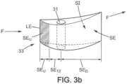
- Reference 31 designates an obstacle which is located in the flow F
- reference 33 designates a fairing element which is in accordance with the invention and which surrounds the obstacle 31.
- a cylindrical coordinate system whose polar coordinate plane is perpendicular to the axis AA, and the Cartesian coordinate axis is superimposed on the axis AA.
- the axial direction is that of the AA axis, and any radial direction intersects the AA axis perpendicularly, being identified by an angle ⁇ around the AA axis according to the polar coordinate system.
- the flow passage section F in a cutting plane that is perpendicular to the axis AA designates the surface that is included between the walls 22 and 23 inside this plane. It can vary when the cutting plane is moved along the axis AA, increasing or decreasing depending on the design of the turbomachine 100.
- the mean radius of the flow passage F, measured radially from the axis AA can also increase or decrease when moving the cutting plane along the axis AA.
- the passage section is designated by S and the average passage radius is designated by r m .
- Nominal values of the flow F at the stator 20 are defined by the air flow as it results from an operating regime identified for the turbomachine 100, when the stator 20 does not include a fairing element 33. These nominal values, which characterize a flow regime taken as a reference, determine in particular the air speed at an upstream end of a fairing element which is intended to be incorporated in the stator 20, with the orientation of this speed, for each point of the corresponding passage section.
- This air speed has an axial component, v z , which is parallel to the axis AA, a radial component, v r , which is oriented radially and perpendicular to the axis AA, and a tangential component, ve, which is oriented perpendicular to the axial and radial directions at the location where this speed is characterized.
- the inventors have discovered that the construction of the upstream portion of the extrados surface in accordance with steps /a/ to /c/ reduces the alteration of the flow pressure field caused by the fairing element, compared to the nominal values. Furthermore, this reduction is sufficient when the construction is extended to a dimension on the A-A axis where the thickness of the fairing element as completed in step /d/, is at least equal to 50% of the thickness of the obstacle.
- this construction of the upstream portion of the extrados surface ensures that the air pressure in the flow in the presence of the fairing element remains substantially the same on the upstream portion of the extrados surface as its values in the absence of the fairing element and the obstacle, when the flow production conditions are identical to those of the nominal values.
- An upper limit of 5%, preferably 3% or better 2%, for the pressure variations that exist in the upstream portion of the extrados surface relative to the nominal pressure value on the leading edge ensures that the disturbances caused by the fairing element upstream thereof are not disturbing, even when a rotor is arranged upstream of the fairing element as close as possible.
- the inventors have also discovered that the evolution of the passage section S and of the mean radius r m as a function of the dimension z on the axis AA, at the location of the upstream part of the extrados surface, determine the curvature of this upstream part of the extrados surface along the streamlines.
- the upstream part of the extrados surface has a convexity which is all the greater as the passage section S decreases in the direction of the flow F at the location of this upstream part of the extrados surface.
- This first variation results from a conservation of the flow rate of the flow F parallel to the axis AA.
- the convexity of the upstream part of the extrados surface is all the greater as the mean passage radius r m increases in the direction of flow F at the location of this upstream part of the extrados surface.
- the two variations of the convexity of the extrados surface SE in its upstream part SEu combine with each other, and possibly also with other contributions that result from different causes, such as for example a variation of air temperature parallel to the axis A-A, or effects of air viscosity.
- the steps /b/ and /c/ indicated above allow to optimize the upstream part of each extrados surface to take into account variations of passage section and mean passage radius that may be present at this upstream part of the extrados surface.
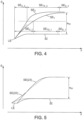
- FIG. 4 is a diagram which superimposes the cross-sections of two fairing elements according to the invention, such that these sections appear in a cylindrical surface of axis AA.
- the horizontal axis of this diagram is the z axis, and the vertical axis is the polar angle ⁇ .
- the two fairing elements have the same leading edge LE and the same intrados surface SI.
- the references which relate separately to the extrados surface of each fairing element are completed by the index 1 or the index 2, respectively.
- the extrados surface SE 1 of the first fairing element is convex in its upstream part, denoted SE U_1 , corresponding to a preponderant effect of a reduction in the passage section S, while the extrados surface SE 2 of the second fairing element is concave in the corresponding upstream part of the extrados surface, denoted SE U_2 .
- the second fairing element corresponds to a predominant effect of a reduction in the mean passage radius r m .
- the two upstream parts of the extrados surfaces SE U_1 and SE U_2 which are represented in [ Fig. 4 ] correspond to the same direction of incidence of the flow F at the leading edge LE, as indicated by the straight segment in a broken line.
- the limit between the upstream part SE U_1 (respectively SE U_2 ) and the transition zone SE TZ_1 (resp. SE TZ_2 ) of the extrados surface SE 1 (resp. SE 2 ) is chosen to correspond to approximately 60% of the angular thickness e 31 of the obstacle 31 which is intended to be contained in each fairing element.
- its thickness can vary between a few millimeters and 150 mm.
- the upstream part of the extrados surface SE U_2 is shorter than that SE U_1 , parallel to the axis AA.
- the longitudinal bulk of a fairing element which has the extrados surface SE 2 can therefore be reduced, compared to the use of the extrados surface SE 1 .
- This reduction in the length of the fairing element, which is provided by the concavity of the upstream part of the extrados surface, is combined with another possible reduction in the total length of the turbomachine which results from the fusion of a stator blade with the fairing element which surrounds the obstacle.
- step /b/ which has been indicated above is carried out separately from several points of the leading edge LE.
- the curvature which results from step /c/ for the upstream part of the extrados surface SEu can then vary between streamlines of the flow F which pass through different points of the leading edge LE, for the same fairing element.
- Fig. 5 thus shows two extrados surface profiles of the same fairing element according to the invention: one designated by SE(22) to be used at the level of the wall 22, and the other designated by SE(23) to be used at the level of the wall 23.
- SE(22) to be used at the level of the wall 22
- SE(23) to be used at the level of the wall 23.
- the leading edge LE is further back downstream of the flow F at the level of the wall 23 than at the level of the wall 22.
- the upstream part of the extrados surface at the level of the wall 22 is slightly convex while that at the level of the wall 23 is slightly concave.
- the upstream part of the extrados surface SEu is then a non-developable surface.
- the horizontal and vertical axes of [ Fig. 5 ] are the same as those of [ Fig. 4 ], and the intrados surface SI is the same at the level of the two walls 22 and 23.
- a fairing element 33 according to the invention may be isolated within the turbomachine 100, for example to surround a starter transmission between an electric starter motor which is located outside the wall 23 and the rotor 12 which is located inside the wall 22.
- a fairing element 33 may be integrated into a turbomachine stator which is arranged downstream of a rotor blade ring.
- a stator produces a flow straightening function.
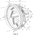
- the stator 20 of [ Fig. 6 ] has an axial configuration, and is provided with a plurality of blades 21 which are angularly stepped around the axis AA.
- the stator 20 may be further provided with a shroud element 33 as described above, or provided with several such shroud elements 33. For example, eight shroud elements 33 may be distributed at an angular equidistant distance in the stator 20, among the blades 21 thereof.
- blades 21, for example twelve blades 21, may be intermediate between two shroud elements 33 which are angularly successive around the axis AA within the stator 20.
- Each shroud element 33 has the first function of surrounding an obstacle 31 to which this shroud element is dedicated.
- each extrados surface SE is designed in accordance with the invention for its upstream part SEu. Its downstream part SE D is then designed to produce the flow straightening function in coherence with the blades 21.
- the blades 21 of the stator 20 may be axially offset between successive blades, in addition to being angularly offset, as can be seen in [ Fig. 6 ].
- two blades 21 which are successive around the axis AA have between them at least the following two offset components: an angular offset component around the axis AA, and an axial offset component which is parallel to the axis AA.
- the blades 21 of the same series which is intermediate between two fairing elements 33 can be aligned obliquely between an upstream part of the intrados surface SI of one of these two fairing elements 33, near its leading edge LE, and a part which is further back towards the downstream of the flow F, of the extrados surface SE of the other fairing element 33, for example its transition zone SE TZ .
- the blades 21 of the same series which is intermediate between two fairing elements 33 can be additionally offset between two successive blades according to an additional offset component, which is radial.
- an additional offset component which is radial.
- each fairing element or a stator which incorporates at least one of these, can be manufactured according to one of the methods known to those skilled in the art, appropriate depending on the location at which the fairing element(s) concerned are located within the turbomachine.
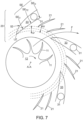
- the invention can also be applied to a stator which has a radial configuration, for example as shown in [ Fig. 2b ].
- a stator which has a radial configuration, for example as shown in [ Fig. 2b ].
- Such a configuration is used for example in a low-pressure compressor, in particular a small turboshaft compressor.
- the stator 20 forms a peripheral crown which is arranged radially around the rotor 12, being coaxial with the latter along the axis AA.
- the stator 20 may comprise several fairing elements 33 which are distributed angularly around the axis AA, each around a different obstacle 31.
- the section plane of [ Fig. 7 ] is indicated in [ Fig. 2b ].
- each fairing element 33 can then be substantially parallel to the axis AA, and its part upstream of the extrados surface SEu is in accordance with the present invention.
- several flow straightening guides 21, for example two guides 21, can be intercalated within the stator 20 with radial configuration between two fairing elements 33 which are successive around the axis AA.
- These two guides 21 can then have progressive radial offsets ⁇ r, for example from the leading edge LE of one of the fairing elements 33 towards the transition zone SE TZ of the extrados surface SE of the following fairing element 33.
- the invention can be reproduced by modifying secondary aspects of the embodiments that have been described in detail above, while retaining at least some of the advantages cited.
- the invention is applicable to any fairing element that is arranged in a fluid passage, regardless of the turbomachine that incorporates this fluid passage and regardless of the location of this fairing element within this machine.
Landscapes
- Engineering & Computer Science (AREA)
- Mechanical Engineering (AREA)
- General Engineering & Computer Science (AREA)
- Physics & Mathematics (AREA)
- Fluid Mechanics (AREA)
- Structures Of Non-Positive Displacement Pumps (AREA)
Applications Claiming Priority (2)
| Application Number | Priority Date | Filing Date | Title |
|---|---|---|---|
| FR2010999A FR3115560B1 (fr) | 2020-10-27 | 2020-10-27 | Element de carenage pour entourer un obstacle dans un ecoulement de fluide |
| PCT/FR2021/051783 WO2022090643A1 (fr) | 2020-10-27 | 2021-10-13 | Element de carenage pour entourer un obstacle dans un ecoulement de fluide |
Publications (2)
| Publication Number | Publication Date |
|---|---|
| EP4237664A1 EP4237664A1 (fr) | 2023-09-06 |
| EP4237664B1 true EP4237664B1 (fr) | 2024-09-25 |
Family
ID=74205995
Family Applications (1)
| Application Number | Title | Priority Date | Filing Date |
|---|---|---|---|
| EP21805566.3A Active EP4237664B1 (fr) | 2020-10-27 | 2021-10-13 | Element de carenage pour entourer un obstacle dans un ecoulement de fluide |
Country Status (6)
| Country | Link |
|---|---|
| US (1) | US12158081B2 (es) |
| EP (1) | EP4237664B1 (es) |
| CA (1) | CA3197071A1 (es) |
| ES (1) | ES2992172T3 (es) |
| FR (1) | FR3115560B1 (es) |
| WO (1) | WO2022090643A1 (es) |
Family Cites Families (6)
| Publication number | Priority date | Publication date | Assignee | Title |
|---|---|---|---|---|
| GB1291235A (en) | 1968-10-02 | 1972-10-04 | Rolls Royce | Fluid flow machine |
| DE102008060847B4 (de) * | 2008-12-06 | 2020-03-19 | MTU Aero Engines AG | Strömungsmaschine |
| US8182204B2 (en) * | 2009-04-24 | 2012-05-22 | Pratt & Whitney Canada Corp. | Deflector for a gas turbine strut and vane assembly |
| US20130051996A1 (en) * | 2011-08-29 | 2013-02-28 | Mtu Aero Engines Gmbh | Transition channel of a turbine unit |
| GB201512838D0 (en) * | 2015-07-21 | 2015-09-02 | Rolls Royce Plc | A turbine stator vane assembly for a turbomachine |
| DE102017212311A1 (de) * | 2017-07-19 | 2019-01-24 | MTU Aero Engines AG | Umströmungsanordung zum Anordnen im Heißgaskanal einer Strömungsmaschine |
-
2020
- 2020-10-27 FR FR2010999A patent/FR3115560B1/fr active Active
-
2021
- 2021-10-13 CA CA3197071A patent/CA3197071A1/fr active Pending
- 2021-10-13 ES ES21805566T patent/ES2992172T3/es active Active
- 2021-10-13 WO PCT/FR2021/051783 patent/WO2022090643A1/fr not_active Ceased
- 2021-10-13 EP EP21805566.3A patent/EP4237664B1/fr active Active
- 2021-10-13 US US18/025,956 patent/US12158081B2/en active Active
Also Published As
| Publication number | Publication date |
|---|---|
| FR3115560B1 (fr) | 2024-02-09 |
| US20230358138A1 (en) | 2023-11-09 |
| ES2992172T3 (es) | 2024-12-10 |
| WO2022090643A1 (fr) | 2022-05-05 |
| US12158081B2 (en) | 2024-12-03 |
| EP4237664A1 (fr) | 2023-09-06 |
| CA3197071A1 (fr) | 2022-05-05 |
| FR3115560A1 (fr) | 2022-04-29 |
Similar Documents
| Publication | Publication Date | Title |
|---|---|---|
| EP3676480B1 (fr) | Aube de redresseur de soufflante de turbomachine, ensemble de turbomachine comprenant une telle aube et turbomachine equipee de ladite aube ou dudit ensemble | |
| FR3153849A1 (fr) | Sous-ensemble de turbomachine comportant un col de cygne a configuration amelioree et turbomachine comportant un tel sous-ensemble | |
| EP3517731B1 (fr) | Ensemble comprenant un passage annulaire entre une virole statique et une plateforme rotorique de turbomachine et procédé correspondant de contrôle de stabilité d'un compresseur | |
| FR3046439A1 (fr) | Soufflante a calage variable a faible pas d'un turboreacteur | |
| FR2669687A1 (fr) | Compresseur a flux axial. | |
| EP4237664B1 (fr) | Element de carenage pour entourer un obstacle dans un ecoulement de fluide | |
| EP4388178A1 (fr) | Pièce statorique d'une turbomachine comprenant une pale et une ailette définissant entre elles une surface décroissante d'amont en aval selon le sens d'écoulement des gaz | |
| EP4077880B1 (fr) | Module pour turbomachine | |
| EP4483040A1 (fr) | Aubage de turbomachine, comprenant une pale et une plateforme qui présente un canal interne d'aspiration et d'éjection de flux | |
| WO2017187093A1 (fr) | Ensemble de redressement de flux d'air et turbomachine comprenant un tel ensemble | |
| BE1030039B1 (fr) | Separateur de flux dans une turbomachine | |
| BE1024523A1 (fr) | Stator a aubes ajustables pour compresseur de turbomachine axiale | |
| BE1030472B1 (fr) | Separateur de flux dans une turbomachine triple-flux | |
| EP4229286B1 (fr) | Système propulsif aéronautique ayant un rendement propulsif amélioré | |
| BE1028097B1 (fr) | Aube de compresseur de turbomachine, compresseur et turbomachine munis de celle-ci | |
| EP4695503A1 (fr) | Stator a calage variable ameliore et procede utilisant un tel stator | |
| WO2024224017A1 (fr) | Aube à calage variable de propulseur aéronautique non-caréné | |
| EP4630659A1 (fr) | Ensemble statorique pour turbomachine et turbomachine | |
| EP4571076A1 (fr) | Module de turbomachine comprenant des aubes rotoriques et des ailettes, et turbomachine correspondante | |
| EP4240650A1 (fr) | Entrée d'air de nacelle d'ensemble propulsif d'aéronef pour favoriser une phase d'inversion de poussée | |
| WO2025149724A1 (fr) | Ensemble statorique de turbomachine comportant des rangées d'aubes en tandem | |
| FR3158951A1 (fr) | Hélice de propulsion pour une turbomachine d’aéronef | |
| WO2025093843A1 (fr) | Aube de redresseur avec une fente |
Legal Events
| Date | Code | Title | Description |
|---|---|---|---|
| STAA | Information on the status of an ep patent application or granted ep patent |
Free format text: STATUS: UNKNOWN |
|
| STAA | Information on the status of an ep patent application or granted ep patent |
Free format text: STATUS: THE INTERNATIONAL PUBLICATION HAS BEEN MADE |
|
| PUAI | Public reference made under article 153(3) epc to a published international application that has entered the european phase |
Free format text: ORIGINAL CODE: 0009012 |
|
| STAA | Information on the status of an ep patent application or granted ep patent |
Free format text: STATUS: REQUEST FOR EXAMINATION WAS MADE |
|
| 17P | Request for examination filed |
Effective date: 20230322 |
|
| AK | Designated contracting states |
Kind code of ref document: A1 Designated state(s): AL AT BE BG CH CY CZ DE DK EE ES FI FR GB GR HR HU IE IS IT LI LT LU LV MC MK MT NL NO PL PT RO RS SE SI SK SM TR |
|
| DAV | Request for validation of the european patent (deleted) | ||
| DAX | Request for extension of the european patent (deleted) | ||
| GRAP | Despatch of communication of intention to grant a patent |
Free format text: ORIGINAL CODE: EPIDOSNIGR1 |
|
| STAA | Information on the status of an ep patent application or granted ep patent |
Free format text: STATUS: GRANT OF PATENT IS INTENDED |
|
| INTG | Intention to grant announced |
Effective date: 20240507 |
|
| GRAS | Grant fee paid |
Free format text: ORIGINAL CODE: EPIDOSNIGR3 |
|
| GRAA | (expected) grant |
Free format text: ORIGINAL CODE: 0009210 |
|
| STAA | Information on the status of an ep patent application or granted ep patent |
Free format text: STATUS: THE PATENT HAS BEEN GRANTED |
|
| AK | Designated contracting states |
Kind code of ref document: B1 Designated state(s): AL AT BE BG CH CY CZ DE DK EE ES FI FR GB GR HR HU IE IS IT LI LT LU LV MC MK MT NL NO PL PT RO RS SE SI SK SM TR |
|
| REG | Reference to a national code |
Ref country code: GB Ref legal event code: FG4D Free format text: NOT ENGLISH |
|
| REG | Reference to a national code |
Ref country code: CH Ref legal event code: EP |
|
| REG | Reference to a national code |
Ref country code: DE Ref legal event code: R096 Ref document number: 602021019397 Country of ref document: DE |
|
| REG | Reference to a national code |
Ref country code: IE Ref legal event code: FG4D Free format text: LANGUAGE OF EP DOCUMENT: FRENCH |
|
| REG | Reference to a national code |
Ref country code: ES Ref legal event code: FG2A Ref document number: 2992172 Country of ref document: ES Kind code of ref document: T3 Effective date: 20241210 |
|
| REG | Reference to a national code |
Ref country code: LT Ref legal event code: MG9D |
|
| PG25 | Lapsed in a contracting state [announced via postgrant information from national office to epo] |
Ref country code: NO Free format text: LAPSE BECAUSE OF FAILURE TO SUBMIT A TRANSLATION OF THE DESCRIPTION OR TO PAY THE FEE WITHIN THE PRESCRIBED TIME-LIMIT Effective date: 20241225 |
|
| PG25 | Lapsed in a contracting state [announced via postgrant information from national office to epo] |
Ref country code: GR Free format text: LAPSE BECAUSE OF FAILURE TO SUBMIT A TRANSLATION OF THE DESCRIPTION OR TO PAY THE FEE WITHIN THE PRESCRIBED TIME-LIMIT Effective date: 20241226 Ref country code: FI Free format text: LAPSE BECAUSE OF FAILURE TO SUBMIT A TRANSLATION OF THE DESCRIPTION OR TO PAY THE FEE WITHIN THE PRESCRIBED TIME-LIMIT Effective date: 20240925 |
|
| PG25 | Lapsed in a contracting state [announced via postgrant information from national office to epo] |
Ref country code: BG Free format text: LAPSE BECAUSE OF FAILURE TO SUBMIT A TRANSLATION OF THE DESCRIPTION OR TO PAY THE FEE WITHIN THE PRESCRIBED TIME-LIMIT Effective date: 20240925 |
|
| PG25 | Lapsed in a contracting state [announced via postgrant information from national office to epo] |
Ref country code: LV Free format text: LAPSE BECAUSE OF FAILURE TO SUBMIT A TRANSLATION OF THE DESCRIPTION OR TO PAY THE FEE WITHIN THE PRESCRIBED TIME-LIMIT Effective date: 20240925 |
|
| PG25 | Lapsed in a contracting state [announced via postgrant information from national office to epo] |
Ref country code: RS Free format text: LAPSE BECAUSE OF FAILURE TO SUBMIT A TRANSLATION OF THE DESCRIPTION OR TO PAY THE FEE WITHIN THE PRESCRIBED TIME-LIMIT Effective date: 20241225 |
|
| REG | Reference to a national code |
Ref country code: NL Ref legal event code: MP Effective date: 20240925 |
|
| PG25 | Lapsed in a contracting state [announced via postgrant information from national office to epo] |
Ref country code: RS Free format text: LAPSE BECAUSE OF FAILURE TO SUBMIT A TRANSLATION OF THE DESCRIPTION OR TO PAY THE FEE WITHIN THE PRESCRIBED TIME-LIMIT Effective date: 20241225 Ref country code: NO Free format text: LAPSE BECAUSE OF FAILURE TO SUBMIT A TRANSLATION OF THE DESCRIPTION OR TO PAY THE FEE WITHIN THE PRESCRIBED TIME-LIMIT Effective date: 20241225 Ref country code: LV Free format text: LAPSE BECAUSE OF FAILURE TO SUBMIT A TRANSLATION OF THE DESCRIPTION OR TO PAY THE FEE WITHIN THE PRESCRIBED TIME-LIMIT Effective date: 20240925 Ref country code: GR Free format text: LAPSE BECAUSE OF FAILURE TO SUBMIT A TRANSLATION OF THE DESCRIPTION OR TO PAY THE FEE WITHIN THE PRESCRIBED TIME-LIMIT Effective date: 20241226 Ref country code: FI Free format text: LAPSE BECAUSE OF FAILURE TO SUBMIT A TRANSLATION OF THE DESCRIPTION OR TO PAY THE FEE WITHIN THE PRESCRIBED TIME-LIMIT Effective date: 20240925 Ref country code: BG Free format text: LAPSE BECAUSE OF FAILURE TO SUBMIT A TRANSLATION OF THE DESCRIPTION OR TO PAY THE FEE WITHIN THE PRESCRIBED TIME-LIMIT Effective date: 20240925 |
|
| REG | Reference to a national code |
Ref country code: AT Ref legal event code: MK05 Ref document number: 1726778 Country of ref document: AT Kind code of ref document: T Effective date: 20240925 |
|
| PG25 | Lapsed in a contracting state [announced via postgrant information from national office to epo] |
Ref country code: NL Free format text: LAPSE BECAUSE OF FAILURE TO SUBMIT A TRANSLATION OF THE DESCRIPTION OR TO PAY THE FEE WITHIN THE PRESCRIBED TIME-LIMIT Effective date: 20240925 |
|
| PG25 | Lapsed in a contracting state [announced via postgrant information from national office to epo] |
Ref country code: IS Free format text: LAPSE BECAUSE OF FAILURE TO SUBMIT A TRANSLATION OF THE DESCRIPTION OR TO PAY THE FEE WITHIN THE PRESCRIBED TIME-LIMIT Effective date: 20250125 Ref country code: PT Free format text: LAPSE BECAUSE OF FAILURE TO SUBMIT A TRANSLATION OF THE DESCRIPTION OR TO PAY THE FEE WITHIN THE PRESCRIBED TIME-LIMIT Effective date: 20250127 |
|
| PG25 | Lapsed in a contracting state [announced via postgrant information from national office to epo] |
Ref country code: SM Free format text: LAPSE BECAUSE OF FAILURE TO SUBMIT A TRANSLATION OF THE DESCRIPTION OR TO PAY THE FEE WITHIN THE PRESCRIBED TIME-LIMIT Effective date: 20240925 Ref country code: RO Free format text: LAPSE BECAUSE OF FAILURE TO SUBMIT A TRANSLATION OF THE DESCRIPTION OR TO PAY THE FEE WITHIN THE PRESCRIBED TIME-LIMIT Effective date: 20240925 |
|
| PG25 | Lapsed in a contracting state [announced via postgrant information from national office to epo] |
Ref country code: EE Free format text: LAPSE BECAUSE OF FAILURE TO SUBMIT A TRANSLATION OF THE DESCRIPTION OR TO PAY THE FEE WITHIN THE PRESCRIBED TIME-LIMIT Effective date: 20240925 Ref country code: AT Free format text: LAPSE BECAUSE OF FAILURE TO SUBMIT A TRANSLATION OF THE DESCRIPTION OR TO PAY THE FEE WITHIN THE PRESCRIBED TIME-LIMIT Effective date: 20240925 |
|
| PG25 | Lapsed in a contracting state [announced via postgrant information from national office to epo] |
Ref country code: PL Free format text: LAPSE BECAUSE OF FAILURE TO SUBMIT A TRANSLATION OF THE DESCRIPTION OR TO PAY THE FEE WITHIN THE PRESCRIBED TIME-LIMIT Effective date: 20240925 Ref country code: CZ Free format text: LAPSE BECAUSE OF FAILURE TO SUBMIT A TRANSLATION OF THE DESCRIPTION OR TO PAY THE FEE WITHIN THE PRESCRIBED TIME-LIMIT Effective date: 20240925 |
|
| PG25 | Lapsed in a contracting state [announced via postgrant information from national office to epo] |
Ref country code: IT Free format text: LAPSE BECAUSE OF FAILURE TO SUBMIT A TRANSLATION OF THE DESCRIPTION OR TO PAY THE FEE WITHIN THE PRESCRIBED TIME-LIMIT Effective date: 20240925 Ref country code: SK Free format text: LAPSE BECAUSE OF FAILURE TO SUBMIT A TRANSLATION OF THE DESCRIPTION OR TO PAY THE FEE WITHIN THE PRESCRIBED TIME-LIMIT Effective date: 20240925 |
|
| REG | Reference to a national code |
Ref country code: CH Ref legal event code: PL |
|
| REG | Reference to a national code |
Ref country code: DE Ref legal event code: R097 Ref document number: 602021019397 Country of ref document: DE |
|
| PG25 | Lapsed in a contracting state [announced via postgrant information from national office to epo] |
Ref country code: MC Free format text: LAPSE BECAUSE OF FAILURE TO SUBMIT A TRANSLATION OF THE DESCRIPTION OR TO PAY THE FEE WITHIN THE PRESCRIBED TIME-LIMIT Effective date: 20240925 |
|
| PG25 | Lapsed in a contracting state [announced via postgrant information from national office to epo] |
Ref country code: DK Free format text: LAPSE BECAUSE OF FAILURE TO SUBMIT A TRANSLATION OF THE DESCRIPTION OR TO PAY THE FEE WITHIN THE PRESCRIBED TIME-LIMIT Effective date: 20240925 |
|
| PG25 | Lapsed in a contracting state [announced via postgrant information from national office to epo] |
Ref country code: LU Free format text: LAPSE BECAUSE OF NON-PAYMENT OF DUE FEES Effective date: 20241013 |
|
| PG25 | Lapsed in a contracting state [announced via postgrant information from national office to epo] |
Ref country code: CH Free format text: LAPSE BECAUSE OF NON-PAYMENT OF DUE FEES Effective date: 20241031 |
|
| PLBE | No opposition filed within time limit |
Free format text: ORIGINAL CODE: 0009261 |
|
| STAA | Information on the status of an ep patent application or granted ep patent |
Free format text: STATUS: NO OPPOSITION FILED WITHIN TIME LIMIT |
|
| 26N | No opposition filed |
Effective date: 20250626 |
|
| PG25 | Lapsed in a contracting state [announced via postgrant information from national office to epo] |
Ref country code: SE Free format text: LAPSE BECAUSE OF FAILURE TO SUBMIT A TRANSLATION OF THE DESCRIPTION OR TO PAY THE FEE WITHIN THE PRESCRIBED TIME-LIMIT Effective date: 20240925 |
|
| PG25 | Lapsed in a contracting state [announced via postgrant information from national office to epo] |
Ref country code: IE Free format text: LAPSE BECAUSE OF NON-PAYMENT OF DUE FEES Effective date: 20241013 |
|
| PGFP | Annual fee paid to national office [announced via postgrant information from national office to epo] |
Ref country code: DE Payment date: 20251126 Year of fee payment: 5 |
|
| PGFP | Annual fee paid to national office [announced via postgrant information from national office to epo] |
Ref country code: GB Payment date: 20251029 Year of fee payment: 5 |
|
| PG25 | Lapsed in a contracting state [announced via postgrant information from national office to epo] |
Ref country code: HR Free format text: LAPSE BECAUSE OF FAILURE TO SUBMIT A TRANSLATION OF THE DESCRIPTION OR TO PAY THE FEE WITHIN THE PRESCRIBED TIME-LIMIT Effective date: 20240925 |
|
| PGFP | Annual fee paid to national office [announced via postgrant information from national office to epo] |
Ref country code: FR Payment date: 20251030 Year of fee payment: 5 |
|
| PGFP | Annual fee paid to national office [announced via postgrant information from national office to epo] |
Ref country code: BE Payment date: 20251030 Year of fee payment: 5 |
|
| PG25 | Lapsed in a contracting state [announced via postgrant information from national office to epo] |
Ref country code: CY Free format text: LAPSE BECAUSE OF FAILURE TO SUBMIT A TRANSLATION OF THE DESCRIPTION OR TO PAY THE FEE WITHIN THE PRESCRIBED TIME-LIMIT; INVALID AB INITIO Effective date: 20211013 |
|
| PG25 | Lapsed in a contracting state [announced via postgrant information from national office to epo] |
Ref country code: HU Free format text: LAPSE BECAUSE OF FAILURE TO SUBMIT A TRANSLATION OF THE DESCRIPTION OR TO PAY THE FEE WITHIN THE PRESCRIBED TIME-LIMIT; INVALID AB INITIO Effective date: 20211013 |
|
| PGFP | Annual fee paid to national office [announced via postgrant information from national office to epo] |
Ref country code: ES Payment date: 20260127 Year of fee payment: 5 |