EP4237334B1 - Gondel für eine flugzeugantriebseinheit mit einer sicherheitsstange zur formung einer strukturellen verstärkung - Google Patents
Gondel für eine flugzeugantriebseinheit mit einer sicherheitsstange zur formung einer strukturellen verstärkung Download PDFInfo
- Publication number
- EP4237334B1 EP4237334B1 EP21810676.3A EP21810676A EP4237334B1 EP 4237334 B1 EP4237334 B1 EP 4237334B1 EP 21810676 A EP21810676 A EP 21810676A EP 4237334 B1 EP4237334 B1 EP 4237334B1
- Authority
- EP
- European Patent Office
- Prior art keywords
- nacelle
- propulsion unit
- connecting rod
- cradle
- aircraft
- Prior art date
- Legal status (The legal status is an assumption and is not a legal conclusion. Google has not performed a legal analysis and makes no representation as to the accuracy of the status listed.)
- Active
Links
Images




Classifications
-
- B—PERFORMING OPERATIONS; TRANSPORTING
- B64—AIRCRAFT; AVIATION; COSMONAUTICS
- B64D—EQUIPMENT FOR FITTING IN OR TO AIRCRAFT; FLIGHT SUITS; PARACHUTES; ARRANGEMENT OR MOUNTING OF POWER PLANTS OR PROPULSION TRANSMISSIONS IN AIRCRAFT
- B64D29/00—Power-plant nacelles, fairings or cowlings
- B64D29/06—Attaching of nacelles, fairings or cowlings
-
- B—PERFORMING OPERATIONS; TRANSPORTING
- B64—AIRCRAFT; AVIATION; COSMONAUTICS
- B64D—EQUIPMENT FOR FITTING IN OR TO AIRCRAFT; FLIGHT SUITS; PARACHUTES; ARRANGEMENT OR MOUNTING OF POWER PLANTS OR PROPULSION TRANSMISSIONS IN AIRCRAFT
- B64D27/00—Arrangement or mounting of power plants in aircraft; Aircraft characterised by the type or position of power plants
- B64D27/40—Arrangements for mounting power plants in aircraft
- B64D27/402—Arrangements for mounting power plants in aircraft comprising box like supporting frames, e.g. pylons or arrangements for embracing the power plant
-
- B—PERFORMING OPERATIONS; TRANSPORTING
- B64—AIRCRAFT; AVIATION; COSMONAUTICS
- B64D—EQUIPMENT FOR FITTING IN OR TO AIRCRAFT; FLIGHT SUITS; PARACHUTES; ARRANGEMENT OR MOUNTING OF POWER PLANTS OR PROPULSION TRANSMISSIONS IN AIRCRAFT
- B64D29/00—Power-plant nacelles, fairings or cowlings
- B64D29/08—Inspection panels for power plants
Definitions
- the invention relates to the field of propulsion systems for aircraft.
- An aircraft propulsion system requires regular inspection, maintenance and/or repair.
- a conventional propulsion unit comprises fan cowls hinged on hinges allowing them to be placed in an open position in which they provide access space to the engine.
- Safety rods known by the acronym “HOR” for "Hold Open Rod” in English, are generally provided to hold the hoods in the open position, for example as described in the document FR 3 025 556 A1 .
- Such safety connecting rods increase the mass of the propulsion unit.
- the document FR 3 075 176 A1 discloses a nacelle for an aircraft propulsion unit, comprising a cowl movable between a closed position and an open position, and a movable connecting rod configured to perform a structural reinforcement function in flight and a function of maintaining the cowl in the open position during maintenance.
- An aim of the invention is to provide a nacelle for an aircraft propulsion unit making it possible to maintain nacelle covers in the open position while reducing the mass constituted by inoperative elements in flight.
- the invention relates to a nacelle for an aircraft propulsion unit, comprising the characteristics of claim 1.
- the connecting rod thus constitutes a means of holding the cowling in the open position, i.e. a safety connecting rod, making it possible to improve the structural strength of the nacelle and the distribution of loads within the propulsion unit and the aircraft in flight.
- the safety connecting rod of the invention therefore has a useful mass in flight.
- the cover comprises connecting means configured to cooperate with the connecting rod in the maintenance position, the connecting rod in the flight position being detached from these connecting means.
- the first component is considered to be distinct from the second component.
- the second component may be a component of the nacelle or, alternatively, a component formed by another part of the aircraft, i.e. a component not belonging to the nacelle.
- the nacelle comprises an air inlet, a rear gas ejection section and a cradle, the cradle extending longitudinally between the air inlet and the rear section and supporting the air inlet and/or the rear section, the cradle comprising attachment means configured to cooperate with the connecting rod in the flight position, the connecting rod in the maintenance position being detached from these attachment means.
- the first component is for example formed by an air inlet or by a rear gas ejection section of the nacelle.
- the invention also relates to a propulsion assembly for an aircraft comprising a turbomachine and a nacelle as defined above.
- the connecting rod in the maintenance position is attached to the turbomachine.
- the invention also relates to an aircraft comprising such a propulsion unit or such a nacelle.
- the aircraft comprises a wing or fuselage or empennage element forming said second component.
- the invention also relates to a method of inspecting and/or maintaining a propulsion assembly as defined above.
- This method comprises a step of moving the hood from the closed position to the open position and a step of moving the connecting rod from the flight position to the maintenance position.
- FIGS. 1 to 15 comprise a reference frame X, Y and Z defining respectively axial (or longitudinal), vertical and lateral directions orthogonal to each other.
- propulsion unit 1 for an aircraft, having a longitudinal central axis A1 parallel to the axial direction X.
- the propulsion unit 1 comprises a nacelle 2 and a turbomachine 3.
- the turbomachine 3 is a dual-flow turbojet comprising, in a manner known per se, a fan 4, a gas generator 5 and an external casing 6 connected to the gas generator 5 by structural arms 7.
- the longitudinal central axis A1 forms an axis of rotation of a rotor of the turbomachine 3.
- the external casing 6 of the turbomachine 3 extends axially towards the front of the propulsion unit 1 so as to surround the fan 4.
- front and rear are defined relative to a direction S1 of gas flow through the propulsion assembly 1 in the axial direction X.
- the nacelle 2 comprises, from front to rear, a front section 10 forming an air intake, an intermediate section 11 comprising fan cowls (see below), and a rear gas ejection section 12.
- the rear section 12 is a fixed shroud.
- the rear section 12 includes a thrust reverser (not shown).
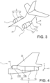
- FIG. 2 shows a propulsion unit 1 mounted vertically under a wing 20 of an aircraft.
- FIG 4 shows a propulsion unit 1 mounted on a fuselage 21 of an aircraft, in the extension of the fuselage 21 in the longitudinal direction X and extending vertically under a tailplane 22 of the aircraft.
- the propulsion units 1 illustrated on the Figures 2 to 4 are in these examples similar to that of the figure 1 .
- the air inlet 10 comprises an air capture section 10A and an “S”-shaped section 10B connecting the section 10A and the intermediate section 11 of the nacelle 2 to each other.
- the propulsion assembly 1 further comprises an inlet cone 15 making it possible to slow down the flow of air entering the air inlet 10.
- the nacelle 2 and the turbomachine 3 of the propulsion unit 1 are supported by a support structure described in more detail below.
- the support structure forms part of the fuselage 21.
- the invention is applicable to each of the configurations of the Figures 2 to 4 and to variants of these configurations.
- the invention can also be implemented in a propulsion unit 1 without an inlet cone and mounted according to the configuration of the figure 2 Or 4 , or to a propulsion unit 1 comprising an inlet cone and mounted according to the configuration of the figure 3 .
- the invention also applies to a propulsion unit whose turbomachine is different from that illustrated in figure 1 .
- the turbomachine may be a single or double flow turbojet and may or may not include afterburner.
- the support structure belongs to the propulsion assembly 1.
- the invention is of particular interest for a propulsion unit 1 having an architecture such as illustrated in the figure 5 .
- the invention can be implemented within a propulsion unit having a conventional architecture or one different from that of the figure 5 (see further below).
- the propulsion unit 1 of the figure 5 comprises a support structure 30 which forms in this example a wing frame part 20, according to the configuration of the figure 2 .
- the turbomachine 3 is connected to the support structure 30 by first connecting means 31.
- the first connecting means 31 comprise suspension arms configured to support the turbomachine 3.
- the propulsion unit 1 of the figure 5 further comprises an intermediate support structure 33 fixed to the support structure 30 by fixing members 34.
- the air inlet 10 and the rear section 12 are each connected to the intermediate support structure 33 by connecting means 35 and 36, respectively.
- the intermediate support structure 33 and the connecting means 35 and 36 form second connecting means, distinct from the first connecting means 31.
- turbomachine 3 on the one hand and the air intake 10 and the rear section 12 of the nacelle 2 on the other hand are supported by the support structure 30 independently.
- the architecture of the propulsion unit of the figure 5 allows the mass of the turbomachine 3 to be reduced, the latter therefore being able to be devoid of fixing flanges for the air intake 10 and the rear section 12, and allows avoiding generating significant loads on the turbomachine 3 and thus affecting its dynamic behavior.
- the second connecting means may be devoid of such an intermediate support structure 33 and the air inlet 10 and/or the rear section 12 of the nacelle 2 may be directly fixed to the support structure 30.
- the air inlet 10 and the rear section 12 are connected to the intermediate support structure 33.
- the air inlet 10 is connected to the intermediate support structure 33 while the rear section 12 is directly connected to the support structure 30.
- the rear section 12 is connected to the intermediate support structure 33 while the air inlet 10 is directly connected to the support structure 30.
- the air inlet 10 and the rear section 12 are directly connected to the support structure 30.
- the intermediate support structure 33 forms a cradle as illustrated in figure 6 .
- the cradle 33 comprises side members 40 and ring sections 41, 42 and 43 connected to each other so as to form a lattice structure.
- the cradle 33 comprises six longitudinal members 40 extending parallel to the axial direction X and being circumferentially spaced from each other, as well as six ring sections 41, 42 and 43 spaced from each other along the axial direction X.
- the cradle of the figure 6 has a plane of symmetry ZX passing through the longitudinal central axis A1, three of said side members 40 extending on one side of this plane of symmetry and the other three side members 40 extending on the other side of this plane of symmetry.
- the ring section 41 is located at one of the axial ends of the cradle 33 and forms a front frame.
- the ring section 43 is located at the other axial end of the cradle 33 and forms a rear frame.
- the ring sections 42 extend axially between the front frame 41 and the rear frame 43.
- the ring sections 41, 42 and 43 and consequently the cradle 33 as a whole extend circumferentially around the longitudinal central axis A1.
- the cradle 33 has a circumferential dimension less than 180°, this dimension being in this case defined by the circumferential dimension of each of the ring sections 41, 42 and 43.
- FIG. 7 shows the cradle 33 partially covered with external skins 49 forming a fairing.
- the air inlet 10 of the nacelle 2 is in this example mounted cantilevered on the cradle 33, being connected to the front frame 41 of the cradle 33 by the connecting means 35.
- the rear section 12 of the nacelle 2 is in this example mounted cantilevered on the cradle 33, being connected to the rear frame 43 of the cradle 33 by the connecting means 36.
- the air inlet 10 and the rear section 12 of the nacelle 2 are in axial support, or capable of coming into axial support, respectively on the front frame 41 and the rear frame 43 of the cradle 33, that is to say on a circumferential sector less than 180°.
- the front frame 41 and/or the rear frame 43 of the cradle 33 are annular so that the air inlet 10 and/or the rear section 12 are mounted over their entire circumference in axial support on the cradle 33.
- the suspension arms 31 of the turbomachine 3 pass through openings formed by the cradle 33 (see figures 5, 6 And 8 ), that is to say openings delimited axially by two respective ring sections and by two respective side members of the cradle 33.
- the concept of having the intermediate support structure 33, and more generally the second connecting means, pass through the first connecting means 31 is also applicable to an intermediate support structure having a geometry different from that of the cradle of the figure 6 .
- the intermediate support structure is a beam
- openings may be provided in the beam such that the first connecting means may extend through these openings (not shown).
- FIG 8 shows a part of an aircraft comprising a propulsion unit 1 presenting the architecture of the figure 5 and comprising as an intermediate support structure 33 the cradle of the figure 6 .
- the figure 8 shows a frame 30 of an aircraft wing 20, the cradle 33 and the turbomachine 3 fixed to the frame 30 by the suspension arms 31 (only one arm being visible in this figure).
- the members 34 for fixing the cradle 33 to the frame 30 are not visible in the figure 8 .
- FIGS. 9 and 10 schematically show fan cowls 50 which are each connected to a structure of a propulsion unit 1 by a pivot connection 51 allowing them to be moved between a closed position ( figure 9 ) and an open position ( figure 10 ).
- the propulsion unit 1 has an architecture as shown in the figure 5 and the structure to which the covers 50 are connected is the cradle 33 of the figure 6 .
- the covers 50 are connected to the support structure 30 of a propulsion assembly 1 such as that of the figure 5 or to another structure of a propulsion unit or of an aircraft having an architecture which may be similar or different from that of the figure 5 .
- the following description applies by analogy to these alternative embodiments.
- the covers 50 cover the turbomachine 3 so as to constitute an external fairing of the intermediate section 11 of the nacelle 2.
- each of the covers 50 is movable between the closed and open positions, preferably under the action of a jack (not shown), in rotation around an axis defined by the corresponding pivot connection 51.
- the invention relates more specifically to a system comprising one or more connecting rods 55 provided to fulfill both a structural reinforcement function when the propulsion assembly 1 is in a flight configuration, in which the cowls 50 are in the closed position, and a function of maintaining the cowls 50 in the open position when the propulsion assembly 1 is in a maintenance configuration.
- the propulsion unit 1 of figures 9 and following comprises two half-parts symmetrical to each other and extending on either side of a median longitudinal plane which is parallel to a plane defined by the directions Y and X, that is to say in this case a vertical plane, passing through the central longitudinal axis A1 of the propulsion unit 1.
- the two half-parts are not symmetrical with respect to each other.
- Each of these half-parts comprises a respective one of the covers 50.
- the propulsion unit 1 has an architecture as illustrated in the figure 5 .
- This propulsion unit 1 includes two connecting rods 55.
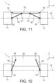
- the connecting rods 55 are in a flight position in which they are configured to perform a structural reinforcement function.
- One of these 55 connecting rods comprises a first end connected to the air inlet 10 by a connecting means 60 and a second end connected to the intermediate support structure 33, in this example the cradle of the figure 6 , by a connecting means 61 also called “attachment means”.
- the other connecting rod 55 called “rear connecting rod” (on the right on the figure 11 ), comprises a first end connected to the rear section 12 by a connecting means 62 and a second end connected to the cradle 33 by a connecting means 63 also called “attachment means”.
- the connecting rods 55 in the flight position extend obliquely relative to the longitudinal X and vertical Y directions so that the front connecting rod can transmit forces between the air inlet 10 and the cradle 33 and the rear connecting rod between the rear section 12 and the cradle 33.
- the connecting rods 55 are movable between the flight position of the figure 11 and a maintenance position illustrated on the figure 12 .
- the connecting means 60 connecting the front connecting rod 55 and the air intake 10 to each other forms a pivot connection and the connecting means 61 forms a detachable connection allowing the front connecting rod 55 and the cradle 33 to be separated from each other - the cradle 33 is visible in the figure. figure 11 but no on the figure 12 ; conversely, the hood 50 is visible on the figure 12 but no on the figure 11 .
- the connecting means 62 connecting the rear connecting rod 55 and the rear section 10 to each other forms a pivot connection and the connecting means 63 forms a detachable connection making it possible to separate the rear connecting rod 55 and the cradle 33 from each other.
- each of the connecting means 60 and 62 comprises a yoke (not shown) fixed to the air inlet 10 or the rear section 12, respectively, the connecting rods 55 comprising an axis (not shown) configured to cooperate with the corresponding yoke to form said pivot connection.
- Each of the connecting means 61 and 63 comprises in this example at least part of a ball pin mechanism known by the English name “quick-release pin” and making it possible to quickly connect/disconnect each of the connecting rods 55 and the cradle 33 relative to each other.
- connecting means 61 and 63 can comprise any other locking-unlocking mechanism, including a screw-nut type mechanism if the duration of maintenance interventions is not very restrictive in the applications envisaged.
- the cover 50 comprises two connecting means 64 and 65 each configured to cooperate with the second end of a respective one of the connecting rods 55 when the latter are in the maintenance position.
- the connecting means 64 and 65 are similar to the connecting means 61 and 63 and therefore comprise, in this example, at least part of a ball pin mechanism for quickly connecting/disconnecting each of the connecting rods 55 and the cover 50 relative to each other.
- the ball pin mechanism can of course be replaced by another locking means (not shown).
- the connecting rods 55 in the maintenance position are configured to perform a function of holding the hood 50 in the open position.
- the connecting rods 55 are manually separated from the cover 50 then moved relative to the cradle 33 according to their respective pivot connection 60 or 62.
- the connecting rods 55 in the flight position are detached from the cowl 50 and cooperate with the air inlet 10, the rear section 12 and the cradle 33 while, in the maintenance position, they are detached from the cradle 33 and cooperate with the air inlet 10, the rear section 12 and the cowl 50.
- the cover 50 In order to carry out an inspection and/or maintenance operation on the propulsion unit 1 starting from a flight configuration in which the cover 50 is in the closed position and in which the connecting rods 55 are in the flight position, the cover 50 is moved from the closed position to the open position and then the connecting rods 55 are moved from the flight position to the maintenance position.
- pivot connection formed by the connecting means 60 and 62 can be replaced by a ball joint connection.
- either or both of the connecting rods 55 may be detachable from both sides.
- the connecting means 60 and 61 of the figure 11 can both be of the detachable type and, with reference to the figure 13 , the intermediate support structure 33 and the cover 50 may each comprise a corresponding detachable connecting means 66 and 67, respectively.
- the front connecting rod 55 in flight position ( figure 11 ), cooperates with the air inlet 10 and the cradle 33 via the connecting means 60 and 61, respectively, and is detached from the hood 50.
- the front connecting rod 55 In the maintenance position ( figure 13 ), the front connecting rod 55 is detached from the air inlet 10 and cooperates with the cradle 33 and the hood 50 via the connecting means 66 and 67, respectively, so as to keep the hood in the open position.
- the turbomachine 3 and the cover 50 each comprise a connecting means 66 and 69, respectively, of the detachable type so that, in the maintenance position, the front connecting rod 55 is detached from the air inlet 10 and cooperates with the turbomachine 3 and the cover 50 via the connecting means 68 and 69, respectively, so as to maintain the cover 50 in the open position.
- the connecting rods 55 have any geometry adapted to the architecture of the propulsion assembly 1, for example a straight or curved shape so as to match, for example, the contours of the turbomachine 3.
- the 55 connecting rods can be telescopic in order to have a different length in the flight position and in the maintenance position.
- the number of connecting rods 55 can be adapted according to the dimensions and architecture of the propulsion unit 1 as well as the effective loads to which they must be subjected.
- the rear section 12 does not include a thrust reverser
- only the front connecting rod can be used.
- the absence of a reverser makes it possible to reduce the mechanical constraints and, in this example, to do without the rear connecting rod.
- FIG 15 shows another type of propulsion assembly architecture 1 particularly adapted, but in no way limited, to an assembly conforming to the figure 4 .
- the propulsion unit 1 of the figure 15 comprises a front connecting rod 55 cooperating in the flight position not with the air intake 10 but with a structure 70 forming in this example a part of the fuselage 21 of the aircraft.
- the structure 70 comprises a connecting means 71 similar to the connecting means 60 of the figure 11 .
- the connecting rod(s) 55 may cooperate in the flight position not with the intermediate support structure 33 of a compliant architecture to the figure 5 but with a support structure 30 capable of forming a wing or fuselage or empennage element of the aircraft.
- the connecting means 61 and 63 can be arranged so that the connecting rods 55 in the flight position cooperate with a support structure 30 forming part of the empennage 22 of the aircraft.
Landscapes
- Engineering & Computer Science (AREA)
- Aviation & Aerospace Engineering (AREA)
- Structures Of Non-Positive Displacement Pumps (AREA)
- Manufacturing & Machinery (AREA)
- Transportation (AREA)
- Wind Motors (AREA)
Claims (8)
- Gondel (2) für eine Antriebseinheit (1) eines Luftfahrzeugs, umfassend mindestens eine zwischen einer geschlossenen Position und einer offenen Position bewegliche Abdeckung (50), derart, dass sie mindestens eine verschiebbare Stange (55) umfasst, die konfiguriert ist, um Folgendes zu erfüllen:- eine erste Funktion zur strukturellen Verstärkung, wenn sie in einer Flugposition platziert ist, wobei die Stange (55) in Flugposition konfiguriert ist, um Kräfte zwischen einer ersten Komponente (10, 12) der Gondel (2) und einer zweiten Komponente (33, 20, 21, 22) der Gondel (2), oder die durch einen anderen Teil des Luftfahrzeugs gebildet wird, zu übertragen, und- eine zweite Funktion zum Halten, wenn sie in einer Wartungsposition platziert ist, wobei die Stange in Wartungsposition imstande ist, die Abdeckung (50) in offener Position zu halten,und derart, dass die Abdeckung (50) Verbindungsmittel (64, 65, 67, 69) umfasst, die konfiguriert sind, um mit der Stange (55) in Wartungsposition zusammenzuwirken, wobei die Stange (55) in Flugposition von diesen Verbindungsmitteln (64, 65, 67, 69) getrennt ist.
- Gondel (2) nach Anspruch 1, umfassend einen Lufteinlass (10), einen hinteren Abschnitt (12) zum Ausstoßen von Gas, und einen Halter (33), wobei der Halter (33) sich längs zwischen dem Lufteinlass (10) und dem hinteren Abschnitt (12) erstreckt, und den Lufteinlass (10) und/oder den hinteren Abschnitt (12) stützt, wobei der Halter (33) Befestigungsmittel (61, 63) umfasst, die konfiguriert sind, um mit der Stange (55) in Flugposition zusammenzuwirken, wobei die Stange (55) in Wartungsposition von diesen Befestigungsmitteln (61, 63) getrennt ist.
- Gondel (2) nach einem der Ansprüche 1 oder 2, wobei die erste Komponente durch einen Lufteilass (10) oder durch einen hinteren Abschnitt (12) zum Ausstoßen von Gas der Gondel (2) gebildet wird.
- Antriebseinheit (1) für ein Luftfahrzeug, umfassend ein Turbotriebwerk (3) und eine Gondel (2) nach einem der Ansprüche 1 bis 3.
- Antriebseinheit (1) nach Anspruch 4, wobei die Stange (55) in Wartungsposition am Turbotriebwerk (3) fixiert ist.
- Luftfahrzeug, umfassend eine Antriebseinheit (1) nach Anspruch 4 oder 5.
- Luftfahrzeug nach Anspruch 6, umfassend ein Tragflächen- (20) oder Rumpf-(21) oder Leitwerkelement (22), das die zweite Komponente bildet.
- Verfahren zur Inspektion und/oder Wartung einer Antriebseinheit (1) nach Anspruch 4 oder 5, umfassend einen Schritt zum Verschieben der Abdeckung (50) von der geschlossenen Position in die offene Position, und einen Schritt zum Verschieben der Stange (55) von der Flugposition in die Wartungsposition.
Applications Claiming Priority (2)
| Application Number | Priority Date | Filing Date | Title |
|---|---|---|---|
| FR2011205A FR3115766B1 (fr) | 2020-11-02 | 2020-11-02 | Nacelle pour ensemble propulsif d’aéronef, comprenant une bielle de sécurité formant renfort structural |
| PCT/FR2021/051916 WO2022090676A1 (fr) | 2020-11-02 | 2021-11-02 | Nacelle pour ensemble propulsif d'aéronef, comprenant une bielle de sécurité formant renfort structural. |
Publications (2)
| Publication Number | Publication Date |
|---|---|
| EP4237334A1 EP4237334A1 (de) | 2023-09-06 |
| EP4237334B1 true EP4237334B1 (de) | 2025-01-01 |
Family
ID=74045833
Family Applications (1)
| Application Number | Title | Priority Date | Filing Date |
|---|---|---|---|
| EP21810676.3A Active EP4237334B1 (de) | 2020-11-02 | 2021-11-02 | Gondel für eine flugzeugantriebseinheit mit einer sicherheitsstange zur formung einer strukturellen verstärkung |
Country Status (4)
| Country | Link |
|---|---|
| US (1) | US12528593B2 (de) |
| EP (1) | EP4237334B1 (de) |
| FR (1) | FR3115766B1 (de) |
| WO (1) | WO2022090676A1 (de) |
Family Cites Families (10)
| Publication number | Priority date | Publication date | Assignee | Title |
|---|---|---|---|---|
| US4399966A (en) * | 1980-12-31 | 1983-08-23 | The Boeing Company | Power opening system for engine cowl doors |
| US4585189A (en) * | 1984-10-22 | 1986-04-29 | Lockheed Corporation | Counterbalanced cowling assembly for a pylon-mounted engine and nacelle therefor |
| FR2771710B1 (fr) * | 1997-12-03 | 2000-02-11 | Aerospatiale | Dispositif d'ouverture commun a deux capots adjacents de nacelle de moteur d'avion |
| US7090165B2 (en) * | 2003-06-02 | 2006-08-15 | Rolls-Royce Plc | Aeroengine nacelle |
| FR2873988B1 (fr) * | 2004-08-05 | 2007-12-21 | Airbus France Sas | Mat d'accrochage de turboreacteur pour aeronef |
| FR2920177B1 (fr) * | 2007-08-20 | 2009-09-18 | Aircelle Sa | Dispositif de liaison, destine a relier un premier et second elements mobiles l'un par rapport a l'autre |
| FR3025556B1 (fr) | 2014-09-08 | 2016-09-09 | Aircelle Sa | Ensemble propulsif pour aeronef et procede d’ouverture d’un capot mobile dudit ensemble propulsif |
| FR3040044B1 (fr) * | 2015-08-12 | 2019-05-31 | Safran Aircraft Engines | Capot de nacelle comportant un element de maintien en position solidarise a la paroi interne du capot |
| EP3635815B1 (de) * | 2017-06-05 | 2022-06-01 | The Nordam Group LLC | Zugängliche radomanordnung |
| FR3075176B1 (fr) * | 2017-12-18 | 2020-11-06 | Safran Aircraft Engines | Ensemble de capot ouvrant et mecanisme de deploiement |
-
2020
- 2020-11-02 FR FR2011205A patent/FR3115766B1/fr active Active
-
2021
- 2021-11-02 US US18/250,638 patent/US12528593B2/en active Active
- 2021-11-02 WO PCT/FR2021/051916 patent/WO2022090676A1/fr not_active Ceased
- 2021-11-02 EP EP21810676.3A patent/EP4237334B1/de active Active
Also Published As
| Publication number | Publication date |
|---|---|
| US20230382545A1 (en) | 2023-11-30 |
| EP4237334A1 (de) | 2023-09-06 |
| FR3115766B1 (fr) | 2023-03-31 |
| WO2022090676A1 (fr) | 2022-05-05 |
| US12528593B2 (en) | 2026-01-20 |
| FR3115766A1 (fr) | 2022-05-06 |
Similar Documents
| Publication | Publication Date | Title |
|---|---|---|
| EP0960051B1 (de) | Flugzeug-triebwerksanlage mit sicherheitseinrichtungen für das stellen und festhalten von den gebläsehauben | |
| CA2602141C (fr) | Systeme propulsif integre comportant un moteur a turboreacteur a double flux | |
| EP1902951B1 (de) | Antriebssystem mit integriertem Mast für Flugzeuge | |
| EP2185413B1 (de) | An der befestigungstriebwerksaufhängung und am gondellufteinlass angebrachtes gestell zum halten eines fan-coils | |
| EP2244944B1 (de) | Flugzeugtriebwerkanordnung mit abwärts versetzten triebwerkhalterungen auf dem lüftergehäuse | |
| EP2244943B1 (de) | Flugzeugtriebwerkanordnung mit einer ringförmigen lastentransferstruktur um das zentralgehäuse eines turboluftstrahltriebwerks | |
| EP3867503B1 (de) | Motoranordnung für ein flugzeug mit luftöltauscher-systemträger mit optimierter befestigung | |
| FR3061480A1 (fr) | Ensemble moteur pour aeronef comprenant une attache moteur avant facilitant son montage | |
| FR3047973A1 (fr) | Ensemble moteur pour aeronef, comprenant un dispositif d'accrochage du moteur equipe de capots mobiles structuraux relies au caisson central | |
| FR2965589A1 (fr) | Inverseur de poussee | |
| FR3032421A1 (fr) | Ensemble pour aeronef comprenant une structure primaire de mat d'accrochage integree a la structure de l'element de voilure | |
| FR3045570A1 (fr) | Ensemble moteur pour aeronef, comprenant un dispositif d'accrochage du moteur equipe d'une enveloppe structurale fixee sur un caisson central | |
| FR3025556A1 (fr) | Ensemble propulsif pour aeronef et procede d’ouverture d’un capot mobile dudit ensemble propulsif | |
| EP4237325B1 (de) | Flugzeugantriebseinheit mit einer von einem flügel-, rumpf- oder heckelement unabhängig unterstützten gondel und einer turbomaschine | |
| WO2012045965A1 (fr) | Ensemble propulsif d'aéronef | |
| FR2940359A1 (fr) | Carter d'echappement pour turbomachine, comportant une ferrure d'accrochage dissociee de la virole exterieure. | |
| FR2966125A1 (fr) | Ensemble d'accrochage d'une suspension d'un ensemble propulsif d'aeronef | |
| FR2963608A1 (fr) | Adaptateur destine a etre interpose entre une structure rigide de mat d'accrochage de turbomoteur d'aeronef et un element de voilure | |
| EP4237334A1 (de) | Gondel für eine flugzeugantriebseinheit mit einer sicherheitsstange zur formung einer strukturellen verstärkung | |
| FR3033545A1 (fr) | Nacelle pour ensemble moteur d'aeronef comprenant au moins un capot de nacelle articule a son extremite avant | |
| FR3110547A1 (fr) | Nacelle pour ensemble propulsif à très grand taux de dilution, comprenant une structure interne avant amovible et structurelle | |
| FR3115765A1 (fr) | Nacelle pour ensemble propulsif d’aéronef, comprenant une structure plurifonctionnelle formant renfort structural ou moyen d’accès |
Legal Events
| Date | Code | Title | Description |
|---|---|---|---|
| STAA | Information on the status of an ep patent application or granted ep patent |
Free format text: STATUS: UNKNOWN |
|
| STAA | Information on the status of an ep patent application or granted ep patent |
Free format text: STATUS: THE INTERNATIONAL PUBLICATION HAS BEEN MADE |
|
| PUAI | Public reference made under article 153(3) epc to a published international application that has entered the european phase |
Free format text: ORIGINAL CODE: 0009012 |
|
| STAA | Information on the status of an ep patent application or granted ep patent |
Free format text: STATUS: REQUEST FOR EXAMINATION WAS MADE |
|
| 17P | Request for examination filed |
Effective date: 20230512 |
|
| AK | Designated contracting states |
Kind code of ref document: A1 Designated state(s): AL AT BE BG CH CY CZ DE DK EE ES FI FR GB GR HR HU IE IS IT LI LT LU LV MC MK MT NL NO PL PT RO RS SE SI SK SM TR |
|
| DAV | Request for validation of the european patent (deleted) | ||
| DAX | Request for extension of the european patent (deleted) | ||
| GRAP | Despatch of communication of intention to grant a patent |
Free format text: ORIGINAL CODE: EPIDOSNIGR1 |
|
| STAA | Information on the status of an ep patent application or granted ep patent |
Free format text: STATUS: GRANT OF PATENT IS INTENDED |
|
| RIC1 | Information provided on ipc code assigned before grant |
Ipc: B64D 27/40 20240101ALI20240607BHEP Ipc: B64D 29/08 20060101ALI20240607BHEP Ipc: B64D 29/06 20060101AFI20240607BHEP |
|
| INTG | Intention to grant announced |
Effective date: 20240625 |
|
| GRAS | Grant fee paid |
Free format text: ORIGINAL CODE: EPIDOSNIGR3 |
|
| GRAA | (expected) grant |
Free format text: ORIGINAL CODE: 0009210 |
|
| STAA | Information on the status of an ep patent application or granted ep patent |
Free format text: STATUS: THE PATENT HAS BEEN GRANTED |
|
| AK | Designated contracting states |
Kind code of ref document: B1 Designated state(s): AL AT BE BG CH CY CZ DE DK EE ES FI FR GB GR HR HU IE IS IT LI LT LU LV MC MK MT NL NO PL PT RO RS SE SI SK SM TR |
|
| REG | Reference to a national code |
Ref country code: GB Ref legal event code: FG4D Free format text: NOT ENGLISH |
|
| REG | Reference to a national code |
Ref country code: CH Ref legal event code: EP |
|
| REG | Reference to a national code |
Ref country code: DE Ref legal event code: R096 Ref document number: 602021024368 Country of ref document: DE |
|
| REG | Reference to a national code |
Ref country code: IE Ref legal event code: FG4D Free format text: LANGUAGE OF EP DOCUMENT: FRENCH |
|
| REG | Reference to a national code |
Ref country code: LT Ref legal event code: MG9D |
|
| REG | Reference to a national code |
Ref country code: NL Ref legal event code: MP Effective date: 20250101 |
|
| REG | Reference to a national code |
Ref country code: AT Ref legal event code: MK05 Ref document number: 1756015 Country of ref document: AT Kind code of ref document: T Effective date: 20250101 |
|
| PG25 | Lapsed in a contracting state [announced via postgrant information from national office to epo] |
Ref country code: NL Free format text: LAPSE BECAUSE OF FAILURE TO SUBMIT A TRANSLATION OF THE DESCRIPTION OR TO PAY THE FEE WITHIN THE PRESCRIBED TIME-LIMIT Effective date: 20250101 |
|
| PG25 | Lapsed in a contracting state [announced via postgrant information from national office to epo] |
Ref country code: FI Free format text: LAPSE BECAUSE OF FAILURE TO SUBMIT A TRANSLATION OF THE DESCRIPTION OR TO PAY THE FEE WITHIN THE PRESCRIBED TIME-LIMIT Effective date: 20250101 |
|
| PG25 | Lapsed in a contracting state [announced via postgrant information from national office to epo] |
Ref country code: PL Free format text: LAPSE BECAUSE OF FAILURE TO SUBMIT A TRANSLATION OF THE DESCRIPTION OR TO PAY THE FEE WITHIN THE PRESCRIBED TIME-LIMIT Effective date: 20250101 |
|
| PG25 | Lapsed in a contracting state [announced via postgrant information from national office to epo] |
Ref country code: ES Free format text: LAPSE BECAUSE OF FAILURE TO SUBMIT A TRANSLATION OF THE DESCRIPTION OR TO PAY THE FEE WITHIN THE PRESCRIBED TIME-LIMIT Effective date: 20250101 |
|
| PG25 | Lapsed in a contracting state [announced via postgrant information from national office to epo] |
Ref country code: IS Free format text: LAPSE BECAUSE OF FAILURE TO SUBMIT A TRANSLATION OF THE DESCRIPTION OR TO PAY THE FEE WITHIN THE PRESCRIBED TIME-LIMIT Effective date: 20250501 Ref country code: NO Free format text: LAPSE BECAUSE OF FAILURE TO SUBMIT A TRANSLATION OF THE DESCRIPTION OR TO PAY THE FEE WITHIN THE PRESCRIBED TIME-LIMIT Effective date: 20250401 |
|
| PG25 | Lapsed in a contracting state [announced via postgrant information from national office to epo] |
Ref country code: HR Free format text: LAPSE BECAUSE OF FAILURE TO SUBMIT A TRANSLATION OF THE DESCRIPTION OR TO PAY THE FEE WITHIN THE PRESCRIBED TIME-LIMIT Effective date: 20250101 |
|
| PG25 | Lapsed in a contracting state [announced via postgrant information from national office to epo] |
Ref country code: PT Free format text: LAPSE BECAUSE OF FAILURE TO SUBMIT A TRANSLATION OF THE DESCRIPTION OR TO PAY THE FEE WITHIN THE PRESCRIBED TIME-LIMIT Effective date: 20250502 Ref country code: LV Free format text: LAPSE BECAUSE OF FAILURE TO SUBMIT A TRANSLATION OF THE DESCRIPTION OR TO PAY THE FEE WITHIN THE PRESCRIBED TIME-LIMIT Effective date: 20250101 |
|
| PG25 | Lapsed in a contracting state [announced via postgrant information from national office to epo] |
Ref country code: GR Free format text: LAPSE BECAUSE OF FAILURE TO SUBMIT A TRANSLATION OF THE DESCRIPTION OR TO PAY THE FEE WITHIN THE PRESCRIBED TIME-LIMIT Effective date: 20250402 Ref country code: BG Free format text: LAPSE BECAUSE OF FAILURE TO SUBMIT A TRANSLATION OF THE DESCRIPTION OR TO PAY THE FEE WITHIN THE PRESCRIBED TIME-LIMIT Effective date: 20250101 |
|
| PG25 | Lapsed in a contracting state [announced via postgrant information from national office to epo] |
Ref country code: AT Free format text: LAPSE BECAUSE OF FAILURE TO SUBMIT A TRANSLATION OF THE DESCRIPTION OR TO PAY THE FEE WITHIN THE PRESCRIBED TIME-LIMIT Effective date: 20250101 |
|
| PG25 | Lapsed in a contracting state [announced via postgrant information from national office to epo] |
Ref country code: CZ Free format text: LAPSE BECAUSE OF FAILURE TO SUBMIT A TRANSLATION OF THE DESCRIPTION OR TO PAY THE FEE WITHIN THE PRESCRIBED TIME-LIMIT Effective date: 20250101 |
|
| PG25 | Lapsed in a contracting state [announced via postgrant information from national office to epo] |
Ref country code: SE Free format text: LAPSE BECAUSE OF FAILURE TO SUBMIT A TRANSLATION OF THE DESCRIPTION OR TO PAY THE FEE WITHIN THE PRESCRIBED TIME-LIMIT Effective date: 20250101 |
|
| REG | Reference to a national code |
Ref country code: DE Ref legal event code: R097 Ref document number: 602021024368 Country of ref document: DE |
|
| PG25 | Lapsed in a contracting state [announced via postgrant information from national office to epo] |
Ref country code: SM Free format text: LAPSE BECAUSE OF FAILURE TO SUBMIT A TRANSLATION OF THE DESCRIPTION OR TO PAY THE FEE WITHIN THE PRESCRIBED TIME-LIMIT Effective date: 20250101 |
|
| PG25 | Lapsed in a contracting state [announced via postgrant information from national office to epo] |
Ref country code: DK Free format text: LAPSE BECAUSE OF FAILURE TO SUBMIT A TRANSLATION OF THE DESCRIPTION OR TO PAY THE FEE WITHIN THE PRESCRIBED TIME-LIMIT Effective date: 20250101 |
|
| PG25 | Lapsed in a contracting state [announced via postgrant information from national office to epo] |
Ref country code: IT Free format text: LAPSE BECAUSE OF FAILURE TO SUBMIT A TRANSLATION OF THE DESCRIPTION OR TO PAY THE FEE WITHIN THE PRESCRIBED TIME-LIMIT Effective date: 20250101 |
|
| PG25 | Lapsed in a contracting state [announced via postgrant information from national office to epo] |
Ref country code: EE Free format text: LAPSE BECAUSE OF FAILURE TO SUBMIT A TRANSLATION OF THE DESCRIPTION OR TO PAY THE FEE WITHIN THE PRESCRIBED TIME-LIMIT Effective date: 20250101 |
|
| PG25 | Lapsed in a contracting state [announced via postgrant information from national office to epo] |
Ref country code: RO Free format text: LAPSE BECAUSE OF FAILURE TO SUBMIT A TRANSLATION OF THE DESCRIPTION OR TO PAY THE FEE WITHIN THE PRESCRIBED TIME-LIMIT Effective date: 20250101 |
|
| PG25 | Lapsed in a contracting state [announced via postgrant information from national office to epo] |
Ref country code: SK Free format text: LAPSE BECAUSE OF FAILURE TO SUBMIT A TRANSLATION OF THE DESCRIPTION OR TO PAY THE FEE WITHIN THE PRESCRIBED TIME-LIMIT Effective date: 20250101 |
|
| PLBE | No opposition filed within time limit |
Free format text: ORIGINAL CODE: 0009261 |
|
| STAA | Information on the status of an ep patent application or granted ep patent |
Free format text: STATUS: NO OPPOSITION FILED WITHIN TIME LIMIT |
|
| 26N | No opposition filed |
Effective date: 20251002 |
|
| PGFP | Annual fee paid to national office [announced via postgrant information from national office to epo] |
Ref country code: DE Payment date: 20251118 Year of fee payment: 5 |
|
| PGFP | Annual fee paid to national office [announced via postgrant information from national office to epo] |
Ref country code: GB Payment date: 20251125 Year of fee payment: 5 |
|
| PGFP | Annual fee paid to national office [announced via postgrant information from national office to epo] |
Ref country code: FR Payment date: 20251125 Year of fee payment: 5 |