EP4237328B1 - Aerodynamische optimierung der grössenbestimmung und schaufelkonstruktionen von gleichdrehenden koaxialen rotoren - Google Patents
Aerodynamische optimierung der grössenbestimmung und schaufelkonstruktionen von gleichdrehenden koaxialen rotoren Download PDFInfo
- Publication number
- EP4237328B1 EP4237328B1 EP20926359.9A EP20926359A EP4237328B1 EP 4237328 B1 EP4237328 B1 EP 4237328B1 EP 20926359 A EP20926359 A EP 20926359A EP 4237328 B1 EP4237328 B1 EP 4237328B1
- Authority
- EP
- European Patent Office
- Prior art keywords
- rotor
- corotating
- parameters
- coaxial
- values
- Prior art date
- Legal status (The legal status is an assumption and is not a legal conclusion. Google has not performed a legal analysis and makes no representation as to the accuracy of the status listed.)
- Active
Links
Images


Classifications
-
- B—PERFORMING OPERATIONS; TRANSPORTING
- B64—AIRCRAFT; AVIATION; COSMONAUTICS
- B64C—AEROPLANES; HELICOPTERS
- B64C27/00—Rotorcraft; Rotors peculiar thereto
- B64C27/04—Helicopters
- B64C27/08—Helicopters with two or more rotors
- B64C27/10—Helicopters with two or more rotors arranged coaxially
-
- B—PERFORMING OPERATIONS; TRANSPORTING
- B64—AIRCRAFT; AVIATION; COSMONAUTICS
- B64C—AEROPLANES; HELICOPTERS
- B64C27/00—Rotorcraft; Rotors peculiar thereto
- B64C27/32—Rotors
- B64C27/46—Blades
- B64C27/467—Aerodynamic features
-
- B—PERFORMING OPERATIONS; TRANSPORTING
- B64—AIRCRAFT; AVIATION; COSMONAUTICS
- B64U—UNMANNED AERIAL VEHICLES [UAV]; EQUIPMENT THEREFOR
- B64U30/00—Means for producing lift; Empennages; Arrangements thereof
- B64U30/20—Rotors; Rotor supports
- B64U30/24—Coaxial rotors
-
- G—PHYSICS
- G01—MEASURING; TESTING
- G01B—MEASURING LENGTH, THICKNESS OR SIMILAR LINEAR DIMENSIONS; MEASURING ANGLES; MEASURING AREAS; MEASURING IRREGULARITIES OF SURFACES OR CONTOURS
- G01B3/00—Measuring instruments characterised by the use of mechanical techniques
Definitions
- the present invention relates broadly to aerodynamic optimization of the sizing and blade designs of corotating coaxial rotors.
- Aerodynamic optimization of the sizing and blade designs of hovering coaxial rotors can be modelled as a pair of dissimilar actuator discs.
- rotational speeds of the upper and lower rotors must be the same in order to maintain a fixed index angle (the angle by which the upper rotor azimuthally leads or lags the lower rotor when corotating in the same rotational directions).
- index angle the angle by which the upper rotor azimuthally leads or lags the lower rotor when corotating in the same rotational directions.
- Embodiments of the present invention seek to improve the aerodynamic optimization of the sizing and blade designs of corotating coaxial rotors.
- a method of generating a set of values for respective ones of a set of parameters used in determining rotor blade profiles for a corotating coaxial rotor system comprising
- a system for generating a set of values for respective ones of a set of parameters used in determining rotor blade profiles for a corotating coaxial rotor system comprising:
- a generalized momentum theory has been developed for application in the aerodynamic optimization of the sizing and blade designs of corotating coaxial rotors with fixed index angles by imposing equality of rotational speeds, while lifting the constraint on equality of torques. Details of the generalized momentum theory are described as follows.
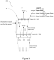
- Figure 3 shows a schematic drawing illustrating a corotating coaxial rotor system 200 modeled with a pair of dissimilar rotors 202, 204.
- Figure 3 is used as a graphical example for describing the following method and it is understood that the method is not limited by Figure 3 .
- the induced power of the lower rotor may be derived according to the following:
- the mass flow through the lower rotor may have two contributions:
- T l ⁇ A l k A ⁇ u + ⁇ l w l ⁇ 2 ⁇ A u ⁇ u 2
- the lower rotor includes two regions.
- the first may be the inner region which lies in the fully developed slipstream of the upper rotor.
- the second may be the outer region which may be unaffected by the upper rotor.
- the individual powers for each of the inner and outer parts may be determined and then summed up.
- an equation for the power per unit thrust of the corotating coaxial system may be determined from the ratio of upper to lower rotor thrusts based on the equality of rotational speeds condition according to the following:
- the cubic equation (27) may be solved for the other induced velocity.
- the specified induced velocity may be determined from the selection of disc loading, which is usually decided upon during the initial stages of the conceptualizing of the corotating coaxial rotor system.
- the selected disc loading may be for the upper rotor, denoted by ( DL ) u .
- the cubic equation (27) may now be solved for the induced velocity of the lower rotor v l .
- the ratio of lower to upper rotor induced velocities may be denoted as k v k ⁇ ⁇ ⁇ l ⁇ u
- the power per unit thrust of the corotating coaxial rotor system may be optimized according to the following:
- the objective of the optimization is to determine the combination of area ratio k A , torque ratio k ⁇ and upper rotor disc loading ( DL ) u which maximizes the hovering efficiency (achieved by minimizing the power per unit thrust P tot / T tot ) as determined by the generalized momentum theory representation of corotating coaxial rotor systems.
- the optimization may be subjected to fulfilling two additional operational requirements:
- Optimization with the quantified operational requirements may be solved by the method of calculus of variations using Lagrange multipliers.
- Two constraint equations may be defined. The first is in relation to the specified thrust and footprint. The second is in relation to the specified k Ttot,spec .
- the equations may be coded and solved numerically in MATLAB ® .
- the equation solver may also be developed in MATLAB ® , and may include
- the developed generalized momentum theory according to an example embodiment is applied in the aerodynamic optimization of the sizing and blade designs of corotating coaxial rotors in conjunction with a calculus of variations, Lagrange multiplier optimization to determine the optimum combination of k A and k ⁇ which achieve a specified total thrust at minimum total induced power of the corotating pair of coaxial rotors, while maintaining equal rotational speeds for the upper and lower rotors.
- the optimization according to the example embodiment using the developed generalized momentum theory is demonstrated in a design example taken from Ref. 2.
- the rotational speed may, for example, be specified for reasons including but not limited to achieving desired rotor tip Mach numbers. e.g. low subsonic Mach numbers for achieving low noise levels.
- the dissimilar rotor diameters and torques resulting from the aerodynamic optimization of the sizing and blade designs of corotating coaxial rotors according to the example embodiment can be used as inputs for the next level of detail: aerodynamic optimization resulting in the details of the geometries of the dissimilar upper and lower rotor blades.
- BEMT Blade Element Momentum Theory
- the method of Ref. 5 contains the following generalizations A) to E):
- the index angle can be chosen to provide additional benefits in aeroacoustics and/or aerodynamics. From an aeroacoustics consideration, corotating rotors inherently do not generate the noise source of pressure impulses of counterrotating rotors when the upper and lower rotor blades cross each other as they rotate in opposite directions, as described in Refs. 6 and 7. Furthermore, the computations of Ref. 8 indicate that, when each of the upper and lower rotors has two blades, index angles in the region of 90° produce destructive interferences between the acoustic waves from the corotating upper and lower rotor blades, which weakens the resulting aerodynamic noise. In consideration of these findings, an index angle of 90° (see numeral 201 in Figure 2 ) is tentatively specified as a geometric parameter according to a nonlimiting example embodiment.
- the resulting corotating pair 200 comprising dissimilar upper and lower rotor blades 202, 204, respectively, is illustrated in Fig. 2 , with the chord distribution, the twist distribution, the pitch angle distribution, and the airfoil distribution etc. for the rotor blades 202, 204 profiles, using the BEMT method according to an example embodiment.
- the lower rotor 204 has a kink 206a, b at the outboard region. This marks the boundary of the downwash from the upper rotor 202 where the downwash contacts with the lower rotor 204.
- this is immersed in the downwash of the upper rotor 202, as illustrated in Fig. 3 , and generates thrust less efficiently due to this interference with the upper rotor.
- the optimizer assigns the inboard region 205 to generate less thrust as compared to the outboard region 207a, b, as a means to reduce the amount of power expended on the inherently less efficient inboard region 205.
- the step change in thrust between the inboard region 205 immersed in the downwash of the upper rotor 202 and the outboard region 207a, b outside of the downwash results in a step change in (optimized) blade chord distribution. Accordingly, the blade profile for the lower rotor 204 contains the kink 206a, b that reflects this step change.
- FM Ideal Power from Generalized Coaxial Momentum Theory Actual Power
- a pre-optimization value of FM using the above definition was determined from experimental measurements of the corotating rotors of Ref 2.
- the FM for the corotating rotors of Ref. 2, as well as the FM after optimization according to the example embodiment of the present invention, are summarized in Table 1.
- the disk loadings are approximately equal, thus allowing for comparisons of FM to be made. It can be seen that in the example embodiment of the present invention, despite negative biasing from operating at lower Reynolds numbers, the optimization is still able to achieve a FM which is substantially higher than in Ref. 2.
- Table 1 Comparison of Figure of Merit (FM) Disk Loading (lb/ft 2 or N/m 2 ) Reynolds Number Upper Rotor Lower Rotor Upper Rotor Lower Rotor FM English Metric English Metric Uehara et al ., 2020 (Ref.
- the index angle may be computed as part of the optimization, rather than being pre-specified.
- aerodynamic considerations may be used in pre-specifying or in optimizing the index angle. For example, Ref. 2 reports that much smaller index angles in the region of 10 0 can yield benefits in additional power loading.
- the number of blades of the upper and lower rotors may be different from two, and/or the upper and lower rotors may have different numbers of blades, e.g upper rotor two blades, lower rotor three blades etc., in different example embodiments
- Figure 4 shows a flowchart 400 illustrating a method of generating a set of values for respective ones of a set of parameters used in determining rotor blade profiles for a corotating coaxial rotor system, according to an example embodiment.
- a ratio of respective desired thrusts of an upper rotor and a lower rotor of the corotating coaxial rotor system is established based on a desired performance of the corotating coaxial rotor system.
- the set of values of the set of parameters is determined from the desired thrusts ratio based on an equal rotation speed condition between the upper rotor and the lower rotor of the corotating coaxial rotor system, wherein the set of parameters includes torques of the upper rotor and the lower rotor.
- the method may comprise establishing a maximum rotor diameter for the corotating coaxial rotor system prior to determining the set of values for the set of parameters and determining the set of values for the set of parameters comprises using the maximum rotor diameter.
- the method may comprise establishing a desired total thrust for the corotating coaxial rotor system prior to determining the set of values for the set of parameters and determining the set of values for the set of parameters comprises using the desired total thrust.
- the method may comprise choosing an index angle of the corotating coaxial rotor system prior to determining the set of values for the set of parameters.
- Determining the set of values for the set of parameters may comprise determining an index angle of the corotating coaxial rotor system.
- Determining the set of values for the set of parameters may comprise optimizing the set of values based on minimizing total induced power for static hover.
- the set of parameters may include a ratio of respective rotor disc areas of the upper rotor and the lower rotor of the corotating coaxial rotor system.
- the set of parameters may include upper rotor diameter and lower rotor diameter.
- the method may comprise assigning an inbound region of the lower rotor from a boundary of downwash from the upper rotor less thrust compared to an outboard region of the lower rotor from the boundary of downwash from the upper rotor.
- the set of parameters include a step change in chord of the lower rotor.
- the ratio of respective desired thrusts of an upper rotor and a lower rotor of the corotating coaxial rotor system may be 1 : 1.
- the torques of the upper rotor and the lower rotor may be included in the set of parameters as a ratio of the torque of the upper rotor and the torque of the lower rotor.
- Figure 5 shows a schematic drawing illustrating a system 500 for generating a set of values for respective ones of a set of parameters used in determining rotor blade profiles for a corotating coaxial rotor system, according to an example embodiment.
- the system 500 comprises means for establishing a ratio of respective desired thrusts, 502, of an upper rotor and a lower rotor of the corotating coaxial rotor system based on a desired performance of the corotating coaxial rotor system; and means for determining the set of values of the set of parameters, 504, from the desired thrusts ratio based on an equal rotation speed condition between the upper rotor and the lower rotor of the corotating coaxial rotor system, wherein the set of parameters includes torques of the upper rotor and the lower rotor.
- the system may comprise means for establishing a maximum rotor diameter, 506, for the corotating coaxial rotor system prior to determining the set of values for the set of parameters and determining the set of values for the set of parameters comprises using the maximum rotor diameter.
- the system may comprise means for establishing a desired total thrust, 508, for the corotating coaxial rotor system prior to determining the set of values for the set of parameters and determining the set of values for the set of parameters comprises using the desired total thrust.
- the system may comprise means for choosing an index angle, 510, of the corotating coaxial rotor system prior to determining the set of values for the set of parameters.
- the means for determining the set of values for the set of parameters, 504, may be configured for determining an index angle of the corotating coaxial rotor system.
- the means for determining the set of values for the set of parameters, 504, may comprise means for optimizing the set of values, 512, based on minimizing total induced power for static hover.
- the set of parameters may include a ratio of respective rotor disc areas of the upper rotor and the lower rotor of the corotating coaxial rotor system.
- the set of parameters may include upper rotor diameter and lower rotor diameter.
- the system may comprise means for assigning, 514, an inbound region of the lower rotor from a boundary of downwash from the upper rotor less thrust compared to an outboard region of the lower rotor from the boundary of downwash from the upper rotor.
- the set of parameters may include a step change in chord of the lower rotor.
- the ratio of respective desired thrusts of an upper rotor and a lower rotor of the corotating coaxial rotor system may be 1 : 1.
- the torques of the upper rotor and the lower rotor may be included in the set of parameters as a ratio of the torque of the upper rotor and the torque of the lower rotor.
- aspects of the systems and methods described herein such as the aerodynamic optimization of the sizing and blade designs of corotating coaxial rotors and the aerodynamic optimization resulting in the details of the geometries of the dissimilar upper and lower rotor blades, for example the means for establishing a ratio of respective desired thrusts, 502, the means for determining the set of values of the set of parameters, 504, the means for establishing a maximum rotor diameter, 506, the means for establishing a desired total thrust, 508, the means for choosing an index angle, 510, the means for optimizing the set of values, 512, and the means for assigning, 514, may be implemented as functionality programmed into any of a variety of circuitry, including programmable logic devices (PLDs), such as field programmable gate arrays (FPGAs), programmable array logic (PAL) devices, electrically programmable logic and memory devices and standard cell-based devices, as well as application specific integrated circuits (ASICs).
- PLDs programmable logic devices
- microcontrollers with memory such as electronically erasable programmable read only memory (EEPROM)
- EEPROM electronically erasable programmable read only memory
- aspects of the system may be embodied in microprocessors having software-based circuit emulation, discrete logic (sequential and combinatorial), custom devices, fuzzy (neural) logic, quantum devices, and hybrids of any of the above device types.
- MOSFET metal-oxide semiconductor field-effect transistor
- CMOS complementary metal-oxide semiconductor
- ECL emitter-coupled logic
- polymer technologies e.g., silicon-conjugated polymer and metal-conjugated polymer-metal structures
- mixed analog and digital etc.
Landscapes
- Engineering & Computer Science (AREA)
- Mechanical Engineering (AREA)
- Aviation & Aerospace Engineering (AREA)
- Physics & Mathematics (AREA)
- Fluid Mechanics (AREA)
- General Physics & Mathematics (AREA)
- Turbine Rotor Nozzle Sealing (AREA)
- Structures Of Non-Positive Displacement Pumps (AREA)
Claims (15)
- Ein Verfahren zum Erzeugen eines Wertesatzes für jeweilige Parameter eines Parametersatzes, der zum Bestimmen von Rotorblattprofilen für ein mitrotierendes koaxiales Rotorsystem verwendet wird, wobei das Verfahren aufweist:Festlegen eines Verhältnisses der jeweiligen gewünschten Schübe eines oberen Rotors und eines unteren Rotors des mitrotierenden koaxialen Rotorsystems basierend auf einer gewünschten Leistung des mitrotierenden koaxialen Rotorsystems; undBestimmen des Wertesatzes des Parametersatzes aus dem gewünschten Schubverhältnis basierend auf einer Bedingung gleicher Rotationsgeschwindigkeit zwischen dem oberen Rotor und dem unteren Rotor des mitrotierenden koaxialen Rotorsystems, wobei der Parametersatz Drehmomente des oberen Rotors und des unteren Rotors aufweist.
- Das Verfahren gemäß Anspruch 1, aufweisend das Festlegen eines maximalen Rotordurchmessers für das mitrotierende koaxiale Rotorsystem vor dem Bestimmen des Wertesatzes für den Parametersatz, und das Bestimmen des Wertesatzes für den Parametersatz weist die Verwendung des maximalen Rotordurchmessers auf.
- Das Verfahren gemäß Anspruch 1 oder 2, aufweisend das Festlegen eines gewünschten Gesamtschubs für das mitrotierende koaxiale Rotorsystem vor dem Bestimmen des Wertesatzes für den Parametersatz, und das Bestimmen des Wertesatzes für den Parametersatz weist das Verwenden des gewünschten Gesamtschubs auf.
- Das Verfahren gemäß einem der Ansprüche 1 bis 3, aufweisend das Wählen eines Indexwinkels des mitrotierenden koaxialen Rotorsystems vor dem Bestimmen des Wertesatzes für den Parametersatz; oder wobei das Bestimmen des Wertesatzes für den Parametersatz das Bestimmen eines Indexwinkels des mitrotierenden koaxialen Rotorsystems aufweist.
- Das Verfahren gemäß einem der Ansprüche 1 bis 4, wobei das Bestimmen des Wertesatzes für den Parametersatz das Optimieren des Wertesatzes basierend auf der Minimierung der gesamten induzierten Leistung für den statischen Schwebeflug aufweist.
- Das Verfahren gemäß einem der Ansprüche 1 bis 5, wobei der Parametersatz ein Verhältnis der jeweiligen Rotorscheibenflächen des oberen Rotors und des unteren Rotors des mitrotierenden koaxialen Rotorsystems aufweist; und wobei der Parametersatz optional den oberen Rotordurchmesser und den unteren Rotordurchmesser aufweist.
- Das Verfahren nach einem der Ansprüche 1 bis 6, aufweisend das Zuweisen eines inneren Bereichs des unteren Rotors von einer Abwindgrenze des oberen Rotors aus mit weniger Schub im Vergleich zu einem äußeren Bereich des unteren Rotors von der Abwindgrenze des oberen Rotors aus nach außen, und wobei der Parametersatz wahlweise eine stufenweise Änderung der Sehne des unteren Rotors aufweist.
- Verfahren nach einem der Ansprüche 1 bis 7, wobei das Verhältnis der jeweiligen gewünschten Schübe eines oberen Rotors und eines unteren Rotors des mitrotierenden koaxialen Rotorsystems 1:1 beträgt; und/oder wobei die Drehmomente des oberen Rotors und des unteren Rotors in den Parametersatz als Verhältnis des Drehmoments des oberen Rotors und des Drehmoments des unteren Rotors einbezogen werden.
- Eine Vorrichtung zum Erzeugen eines Wertesatzes für die jeweiligen Werte eines Parametersatzes, der zum Bestimmen von Rotorblattprofilen für ein mitrotierendes koaxiales Rotorsystem verwendet wird, wobei die Vorrichtung Folgendes aufweist:Mittel zum Festlegen eines Verhältnisses der jeweiligen gewünschten Schübe eines oberen Rotors und eines unteren Rotors des mitrotierenden koaxialen Rotorsystems basierend auf einer gewünschten Leistung des mitrotierenden koaxialen Rotorsystems; undMittel zum Bestimmen des Wertesatzes des Parametersatzes aus dem gewünschten Schubverhältnis basierend auf einer Bedingung gleicher Rotationsgeschwindigkeit zwischen dem oberen Rotor und dem unteren Rotor des mitrotierenden koaxialen Rotorsystems, wobei der Parametersatz Drehmomente des oberen Rotors und des unteren Rotors aufweist.
- Die Vorrichtung gemäß Anspruch 9, aufweisend Mittel zum Festlegen eines maximalen Rotordurchmessers für das mitrotierende koaxiale Rotorsystem vor dem Bestimmen des Wertesatzes für den Parametersatz, wobei das Bestimmen des Wertesatzes für den Parametersatz die Verwendung des maximalen Rotordurchmessers aufweist; und/oder aufweisend Mittel zum Festlegen eines gewünschten Gesamtschubs für das mitrotierende koaxiale Rotorsystem vor dem Bestimmen des Wertesatzes für den Parametersatz, wobei das Bestimmen des Wertesatzes für den Parametersatz die Verwendung des gewünschten Gesamtschubs aufweist.
- Die Vorrichtung gemäß einem der Ansprüche 9 bis 10, aufweisend Mittel zum Wählen eines Indexwinkels des mitrotierenden koaxialen Rotorsystems vor dem Bestimmen des Wertesatzes für den Parametersatz; oder wobei die Mittel zum Bestimmen des Wertesatzes für den Parametersatz zum Bestimmen eines Indexwinkels des mitrotierenden koaxialen Rotorsystems konfiguriert sind.
- Die Vorrichtung gemäß einem der Ansprüche 9 bis 11, wobei die Mittel zum Bestimmen des Wertesatzes für den Parametersatz Mittel zum Optimieren des Wertesatzes auf der Grundlage der Minimierung der gesamten induzierten Leistung für den statischen Schwebeflug aufweisen.
- Die Vorrichtung gemäß einem der Ansprüche 9 bis 12, wobei der Parametersatz ein Verhältnis der jeweiligen Rotorscheibenflächen des oberen Rotors und des unteren Rotors des mitrotierenden koaxialen Rotorsystems aufweist; und wobei der Parametersatz optional den oberen Rotordurchmesser und den unteren Rotordurchmesser aufweist.
- Die Vorrichtung nach einem der Ansprüche 9 bis 13, aufweisend Mittel zum Zuweisen eines inneren Bereichs des unteren Rotors von einer Abwindgrenze des oberen Rotors aus, der weniger Schub hat als ein äußerer Bereich des unteren Rotors von der Abwindgrenze des oberen Rotors aus, und wobei der Parametersatz wahlweise eine stufenweise Änderung der Sehne des unteren Rotors aufweist.
- Die Vorrichtung gemäß einem der Ansprüche 9 bis 14, wobei das Verhältnis der jeweiligen gewünschten Schübe eines oberen Rotors und eines unteren Rotors des mitrotierenden koaxialen Rotorsystems 1:1 beträgt und/oder wobei die Drehmomente des oberen Rotors und des unteren Rotors in den Parametersatz als Verhältnis des Drehmoments des oberen Rotors und des Drehmoments des unteren Rotors einbezogen sind.
Applications Claiming Priority (2)
| Application Number | Priority Date | Filing Date | Title |
|---|---|---|---|
| SG10202010770P | 2020-10-29 | ||
| PCT/SG2020/050745 WO2022093109A1 (en) | 2020-10-29 | 2020-12-14 | Aerodynamic optimization of the sizing and blade designs of corotating coaxial rotors |
Publications (4)
| Publication Number | Publication Date |
|---|---|
| EP4237328A1 EP4237328A1 (de) | 2023-09-06 |
| EP4237328A4 EP4237328A4 (de) | 2024-03-13 |
| EP4237328B1 true EP4237328B1 (de) | 2025-02-12 |
| EP4237328C0 EP4237328C0 (de) | 2025-02-12 |
Family
ID=81384485
Family Applications (1)
| Application Number | Title | Priority Date | Filing Date |
|---|---|---|---|
| EP20926359.9A Active EP4237328B1 (de) | 2020-10-29 | 2020-12-14 | Aerodynamische optimierung der grössenbestimmung und schaufelkonstruktionen von gleichdrehenden koaxialen rotoren |
Country Status (3)
| Country | Link |
|---|---|
| US (1) | US20230084519A1 (de) |
| EP (1) | EP4237328B1 (de) |
| WO (1) | WO2022093109A1 (de) |
Families Citing this family (1)
| Publication number | Priority date | Publication date | Assignee | Title |
|---|---|---|---|---|
| CN120105756B (zh) * | 2025-05-08 | 2025-09-09 | 大连理工大学 | 一种基于多体动力学的直升机复杂构型桨叶建模方法 |
Family Cites Families (6)
| Publication number | Priority date | Publication date | Assignee | Title |
|---|---|---|---|---|
| WO2010134924A1 (en) * | 2009-05-22 | 2010-11-25 | Bell Helicopter Textron Inc. | Co-rotating stacked rotor disks for improved hover performance |
| US10112707B1 (en) * | 2014-10-03 | 2018-10-30 | John V. Howard | Remotely controlled co-axial rotorcraft for heavy-lift aerial-crane operations |
| US20180281949A1 (en) * | 2015-09-09 | 2018-10-04 | Altus IP Limited | Systems and methods for stabilisation of aerial vehicles |
| CN108698688B (zh) * | 2015-12-09 | 2022-06-07 | 新科宇航 | 生成用于确定同轴转子系统的转子叶片轮廓的一组参数中的相应参数的一组值的方法和系统 |
| CN108463406A (zh) * | 2016-09-09 | 2018-08-28 | 深圳市大疆创新科技有限公司 | 一种螺旋桨组件、动力系统及飞行器 |
| US10752352B2 (en) * | 2017-12-07 | 2020-08-25 | Textron Innovations Inc. | Dual rotor propulsion systems for tiltrotor aircraft |
-
2020
- 2020-12-14 WO PCT/SG2020/050745 patent/WO2022093109A1/en not_active Ceased
- 2020-12-14 US US17/800,192 patent/US20230084519A1/en active Pending
- 2020-12-14 EP EP20926359.9A patent/EP4237328B1/de active Active
Also Published As
| Publication number | Publication date |
|---|---|
| EP4237328C0 (de) | 2025-02-12 |
| US20230084519A1 (en) | 2023-03-16 |
| WO2022093109A1 (en) | 2022-05-05 |
| EP4237328A4 (de) | 2024-03-13 |
| EP4237328A1 (de) | 2023-09-06 |
Similar Documents
| Publication | Publication Date | Title |
|---|---|---|
| US20210253236A1 (en) | Rotary airfoil and design therefore | |
| Tung et al. | The prediction of transonic flows on an advancing rotor | |
| Griffiths et al. | Predictions of rotor performance in ground effect using a free‐vortex wake model | |
| Ventura Diaz et al. | The side-by-side urban air taxi concept | |
| Ventura Diaz et al. | Simulations of ducted and coaxial rotors for air taxi operations | |
| Healy et al. | A CFD-based examination of rotor-rotor separation effects on interactional aerodynamics for eVTOL aircraft | |
| US20230084519A1 (en) | Aerodynamic optimization of the sizing and blade designs of corotating coaxial rotors | |
| Wang et al. | Approximately arc-length parametrized C3 quintic interpolatory splines | |
| Jimenez et al. | Effect of duct-rotor aerodynamic interactions on blade design for hover and axial flight | |
| US11014662B2 (en) | Method and system for generating a set of values for respective ones of a set of parameters used in determining rotor blade profiles for a coaxial rotor system | |
| Opazo et al. | Analytical and experimental power minimization for fixed-pitch coaxial rotors in hover | |
| Kallstrom et al. | Airfoil table generation and validation for the vr-12 and ssc-a09 airfoils and quadrotor performance prediction | |
| Lee et al. | Aerodynamic characteristic analysis of multi-rotors using a modified free-wake method | |
| Dangelo | Wide speed range turboshaft study | |
| Gur et al. | Prop-rotor design for an electric tilt-rotor vehicle | |
| Hassan et al. | Airfoil design for helicopter rotor blades-a three-dimensional approach | |
| DiPalma et al. | Optimization of extension-twist coupled composite blades for high-speed rotorcraft | |
| Chan | Aerodynamic optimization of the sizing and blade designs of hovering corotating coaxial rotors | |
| Dayhoum et al. | Aerodynamic Investigation of Shrouded Rotors with Dual Exit Channels | |
| Chung et al. | Numerical predictions of rotorcraft unsteady air-loadings and BVI noise by using a time-marching free-wake and acoustic analogy | |
| SUMMA | Potential flow about three-dimensional lifting configurations, with application to wings and rotors | |
| Mehr et al. | DuctAPE: a steady-state, axisymmetric ducted fan analysis code designed for gradient-based optimization | |
| McCune et al. | Lifting-line theory for subsonic axial compressor rotors | |
| Hong et al. | A dynamic-inflow-based induced power model for general and optimal rotor performance | |
| Tsung et al. | Numerical simulation of flow separation for rotors and fixed wings |
Legal Events
| Date | Code | Title | Description |
|---|---|---|---|
| STAA | Information on the status of an ep patent application or granted ep patent |
Free format text: STATUS: UNKNOWN |
|
| STAA | Information on the status of an ep patent application or granted ep patent |
Free format text: STATUS: THE INTERNATIONAL PUBLICATION HAS BEEN MADE |
|
| PUAI | Public reference made under article 153(3) epc to a published international application that has entered the european phase |
Free format text: ORIGINAL CODE: 0009012 |
|
| STAA | Information on the status of an ep patent application or granted ep patent |
Free format text: STATUS: REQUEST FOR EXAMINATION WAS MADE |
|
| 17P | Request for examination filed |
Effective date: 20210928 |
|
| AK | Designated contracting states |
Kind code of ref document: A1 Designated state(s): AL AT BE BG CH CY CZ DE DK EE ES FI FR GB GR HR HU IE IS IT LI LT LU LV MC MK MT NL NO PL PT RO RS SE SI SK SM TR |
|
| DAV | Request for validation of the european patent (deleted) | ||
| DAX | Request for extension of the european patent (deleted) | ||
| A4 | Supplementary search report drawn up and despatched |
Effective date: 20240212 |
|
| RIC1 | Information provided on ipc code assigned before grant |
Ipc: B64C 27/467 20060101ALI20240206BHEP Ipc: B64C 27/10 20230101AFI20240206BHEP |
|
| GRAP | Despatch of communication of intention to grant a patent |
Free format text: ORIGINAL CODE: EPIDOSNIGR1 |
|
| STAA | Information on the status of an ep patent application or granted ep patent |
Free format text: STATUS: GRANT OF PATENT IS INTENDED |
|
| INTG | Intention to grant announced |
Effective date: 20240829 |
|
| GRAS | Grant fee paid |
Free format text: ORIGINAL CODE: EPIDOSNIGR3 |
|
| GRAA | (expected) grant |
Free format text: ORIGINAL CODE: 0009210 |
|
| STAA | Information on the status of an ep patent application or granted ep patent |
Free format text: STATUS: THE PATENT HAS BEEN GRANTED |
|
| AK | Designated contracting states |
Kind code of ref document: B1 Designated state(s): AL AT BE BG CH CY CZ DE DK EE ES FI FR GB GR HR HU IE IS IT LI LT LU LV MC MK MT NL NO PL PT RO RS SE SI SK SM TR |
|
| REG | Reference to a national code |
Ref country code: GB Ref legal event code: FG4D |
|
| REG | Reference to a national code |
Ref country code: CH Ref legal event code: EP |
|
| REG | Reference to a national code |
Ref country code: DE Ref legal event code: R096 Ref document number: 602020046156 Country of ref document: DE |
|
| REG | Reference to a national code |
Ref country code: IE Ref legal event code: FG4D |
|
| U01 | Request for unitary effect filed |
Effective date: 20250307 |
|
| U07 | Unitary effect registered |
Designated state(s): AT BE BG DE DK EE FI FR IT LT LU LV MT NL PT RO SE SI Effective date: 20250314 |
|
| PG25 | Lapsed in a contracting state [announced via postgrant information from national office to epo] |
Ref country code: RS Free format text: LAPSE BECAUSE OF FAILURE TO SUBMIT A TRANSLATION OF THE DESCRIPTION OR TO PAY THE FEE WITHIN THE PRESCRIBED TIME-LIMIT Effective date: 20250512 |
|
| PG25 | Lapsed in a contracting state [announced via postgrant information from national office to epo] |
Ref country code: PL Free format text: LAPSE BECAUSE OF FAILURE TO SUBMIT A TRANSLATION OF THE DESCRIPTION OR TO PAY THE FEE WITHIN THE PRESCRIBED TIME-LIMIT Effective date: 20250212 |
|
| PG25 | Lapsed in a contracting state [announced via postgrant information from national office to epo] |
Ref country code: ES Free format text: LAPSE BECAUSE OF FAILURE TO SUBMIT A TRANSLATION OF THE DESCRIPTION OR TO PAY THE FEE WITHIN THE PRESCRIBED TIME-LIMIT Effective date: 20250212 |
|
| PG25 | Lapsed in a contracting state [announced via postgrant information from national office to epo] |
Ref country code: IS Free format text: LAPSE BECAUSE OF FAILURE TO SUBMIT A TRANSLATION OF THE DESCRIPTION OR TO PAY THE FEE WITHIN THE PRESCRIBED TIME-LIMIT Effective date: 20250612 Ref country code: NO Free format text: LAPSE BECAUSE OF FAILURE TO SUBMIT A TRANSLATION OF THE DESCRIPTION OR TO PAY THE FEE WITHIN THE PRESCRIBED TIME-LIMIT Effective date: 20250512 |
|
| PG25 | Lapsed in a contracting state [announced via postgrant information from national office to epo] |
Ref country code: HR Free format text: LAPSE BECAUSE OF FAILURE TO SUBMIT A TRANSLATION OF THE DESCRIPTION OR TO PAY THE FEE WITHIN THE PRESCRIBED TIME-LIMIT Effective date: 20250212 |
|
| PG25 | Lapsed in a contracting state [announced via postgrant information from national office to epo] |
Ref country code: GR Free format text: LAPSE BECAUSE OF FAILURE TO SUBMIT A TRANSLATION OF THE DESCRIPTION OR TO PAY THE FEE WITHIN THE PRESCRIBED TIME-LIMIT Effective date: 20250513 |
|
| PG25 | Lapsed in a contracting state [announced via postgrant information from national office to epo] |
Ref country code: SM Free format text: LAPSE BECAUSE OF FAILURE TO SUBMIT A TRANSLATION OF THE DESCRIPTION OR TO PAY THE FEE WITHIN THE PRESCRIBED TIME-LIMIT Effective date: 20250212 |
|
| PG25 | Lapsed in a contracting state [announced via postgrant information from national office to epo] |
Ref country code: CZ Free format text: LAPSE BECAUSE OF FAILURE TO SUBMIT A TRANSLATION OF THE DESCRIPTION OR TO PAY THE FEE WITHIN THE PRESCRIBED TIME-LIMIT Effective date: 20250212 |
|
| PG25 | Lapsed in a contracting state [announced via postgrant information from national office to epo] |
Ref country code: SK Free format text: LAPSE BECAUSE OF FAILURE TO SUBMIT A TRANSLATION OF THE DESCRIPTION OR TO PAY THE FEE WITHIN THE PRESCRIBED TIME-LIMIT Effective date: 20250212 |
|
| PLBE | No opposition filed within time limit |
Free format text: ORIGINAL CODE: 0009261 |
|
| STAA | Information on the status of an ep patent application or granted ep patent |
Free format text: STATUS: NO OPPOSITION FILED WITHIN TIME LIMIT |
|
| PGFP | Annual fee paid to national office [announced via postgrant information from national office to epo] |
Ref country code: GB Payment date: 20251218 Year of fee payment: 6 |
|
| U20 | Renewal fee for the european patent with unitary effect paid |
Year of fee payment: 6 Effective date: 20251210 |
|
| 26N | No opposition filed |
Effective date: 20251113 |