EP4236901B1 - Vorrichtung für unterstützte mobilität - Google Patents
Vorrichtung für unterstützte mobilität Download PDFInfo
- Publication number
- EP4236901B1 EP4236901B1 EP21802361.2A EP21802361A EP4236901B1 EP 4236901 B1 EP4236901 B1 EP 4236901B1 EP 21802361 A EP21802361 A EP 21802361A EP 4236901 B1 EP4236901 B1 EP 4236901B1
- Authority
- EP
- European Patent Office
- Prior art keywords
- spring
- harness
- connecting device
- user
- insert
- Prior art date
- Legal status (The legal status is an assumption and is not a legal conclusion. Google has not performed a legal analysis and makes no representation as to the accuracy of the status listed.)
- Active
Links
Images


Classifications
-
- A—HUMAN NECESSITIES
- A61—MEDICAL OR VETERINARY SCIENCE; HYGIENE
- A61H—PHYSICAL THERAPY APPARATUS, e.g. DEVICES FOR LOCATING OR STIMULATING REFLEX POINTS IN THE BODY; ARTIFICIAL RESPIRATION; MASSAGE; BATHING DEVICES FOR SPECIAL THERAPEUTIC OR HYGIENIC PURPOSES OR SPECIFIC PARTS OF THE BODY
- A61H1/00—Apparatus for passive exercising; Vibrating apparatus; Chiropractic devices, e.g. body impacting devices, external devices for briefly extending or aligning unbroken bones
- A61H1/02—Stretching or bending or torsioning apparatus for exercising
- A61H1/0237—Stretching or bending or torsioning apparatus for exercising for the lower limbs
- A61H1/0244—Hip
-
- A—HUMAN NECESSITIES
- A61—MEDICAL OR VETERINARY SCIENCE; HYGIENE
- A61H—PHYSICAL THERAPY APPARATUS, e.g. DEVICES FOR LOCATING OR STIMULATING REFLEX POINTS IN THE BODY; ARTIFICIAL RESPIRATION; MASSAGE; BATHING DEVICES FOR SPECIAL THERAPEUTIC OR HYGIENIC PURPOSES OR SPECIFIC PARTS OF THE BODY
- A61H3/00—Appliances for aiding patients or disabled persons to walk about
- A61H2003/007—Appliances for aiding patients or disabled persons to walk about secured to the patient, e.g. with belts
-
- A—HUMAN NECESSITIES
- A61—MEDICAL OR VETERINARY SCIENCE; HYGIENE
- A61H—PHYSICAL THERAPY APPARATUS, e.g. DEVICES FOR LOCATING OR STIMULATING REFLEX POINTS IN THE BODY; ARTIFICIAL RESPIRATION; MASSAGE; BATHING DEVICES FOR SPECIAL THERAPEUTIC OR HYGIENIC PURPOSES OR SPECIFIC PARTS OF THE BODY
- A61H2201/00—Characteristics of apparatus not provided for in the preceding codes
- A61H2201/12—Driving means
- A61H2201/1253—Driving means driven by a human being, e.g. hand driven
- A61H2201/1261—Driving means driven by a human being, e.g. hand driven combined with active exercising of the patient
-
- A—HUMAN NECESSITIES
- A61—MEDICAL OR VETERINARY SCIENCE; HYGIENE
- A61H—PHYSICAL THERAPY APPARATUS, e.g. DEVICES FOR LOCATING OR STIMULATING REFLEX POINTS IN THE BODY; ARTIFICIAL RESPIRATION; MASSAGE; BATHING DEVICES FOR SPECIAL THERAPEUTIC OR HYGIENIC PURPOSES OR SPECIFIC PARTS OF THE BODY
- A61H2201/00—Characteristics of apparatus not provided for in the preceding codes
- A61H2201/16—Physical interface with patient
- A61H2201/1602—Physical interface with patient kind of interface, e.g. head rest, knee support or lumbar support
- A61H2201/1628—Pelvis
-
- A—HUMAN NECESSITIES
- A61—MEDICAL OR VETERINARY SCIENCE; HYGIENE
- A61H—PHYSICAL THERAPY APPARATUS, e.g. DEVICES FOR LOCATING OR STIMULATING REFLEX POINTS IN THE BODY; ARTIFICIAL RESPIRATION; MASSAGE; BATHING DEVICES FOR SPECIAL THERAPEUTIC OR HYGIENIC PURPOSES OR SPECIFIC PARTS OF THE BODY
- A61H2201/00—Characteristics of apparatus not provided for in the preceding codes
- A61H2201/16—Physical interface with patient
- A61H2201/1602—Physical interface with patient kind of interface, e.g. head rest, knee support or lumbar support
- A61H2201/164—Feet or leg, e.g. pedal
- A61H2201/1642—Holding means therefor
-
- A—HUMAN NECESSITIES
- A61—MEDICAL OR VETERINARY SCIENCE; HYGIENE
- A61H—PHYSICAL THERAPY APPARATUS, e.g. DEVICES FOR LOCATING OR STIMULATING REFLEX POINTS IN THE BODY; ARTIFICIAL RESPIRATION; MASSAGE; BATHING DEVICES FOR SPECIAL THERAPEUTIC OR HYGIENIC PURPOSES OR SPECIFIC PARTS OF THE BODY
- A61H2201/00—Characteristics of apparatus not provided for in the preceding codes
- A61H2201/16—Physical interface with patient
- A61H2201/1602—Physical interface with patient kind of interface, e.g. head rest, knee support or lumbar support
- A61H2201/165—Wearable interfaces
- A61H2201/1652—Harness
-
- A—HUMAN NECESSITIES
- A61—MEDICAL OR VETERINARY SCIENCE; HYGIENE
- A61H—PHYSICAL THERAPY APPARATUS, e.g. DEVICES FOR LOCATING OR STIMULATING REFLEX POINTS IN THE BODY; ARTIFICIAL RESPIRATION; MASSAGE; BATHING DEVICES FOR SPECIAL THERAPEUTIC OR HYGIENIC PURPOSES OR SPECIFIC PARTS OF THE BODY
- A61H2201/00—Characteristics of apparatus not provided for in the preceding codes
- A61H2201/50—Control means thereof
- A61H2201/5053—Control means thereof mechanically controlled
Definitions
- the present invention relates to an apparatus for assisted mobility.
- the sector to which the invention relates is mobility aids, which are designed to help people with reduced mobility to walk, by reducing fatigue and the loads on the joints.
- the category of persons with reduced walking capacity often includes the elderly and persons with neurodegenerative disorders or other problems linked to injuries, who may have experienced a reduction in muscle mass, thus inevitably reducing walking speed. With aging, furthermore, also comes a reduction in stability and a consequent increase of the risk of falls.
- Robotic aid devices are known for improving walking and reducing the risk of falls, which are powered by electromechanical actuators that apply a torque, thus assisting the joints of the user wearing the device.
- Such devices usually incorporate wearable sensors and means of detecting the different phases of human walking, so as to apply the correct electromechanical assistance.
- US2019380904A1 discloses a device for assisting walking mobility of human during gait to reduce fatigue and loads on joints and has components for transitioning between a first, relaxed state and a second, expanded state during walking,
- the apparatus consists of a harness to be worn around the trunk and of a band or a pair of bands for support, each one to be worn around a leg, and associated with the harness via a respective elastic element, i.e. an elastically deformable element, which is adapted to work being extended during walking or other movements of the body.
- the elastic elements store and release mechanical energy at each step in order to provide an additional torque over and above the natural torque due to the movement. This use of energy helps users of any level of mobility to increase the force of the hip joint for some users who have particularly reduced mobility.
- the bands can be worn both simultaneously or separately and in different positions, based on the needs of the user, for example around the thigh or the knee and/or the lower part of the leg.
- the elastic element has a broad and flat shape structure to maintain a reduced encumbrance. In use, it extends preferably along the front part of the leg, or alternatively along the rear part.
- a connecting element at the upper end (when in use) of the elastic element connects it to a length-adjustable belt, via a ratchet or a buckle. Adjusting the length of the belt can preload the elastic element.
- Another connecting element joins the upper end of the belt to the harness and translates along it for adjusting the position of the elastic element along the leg.
- the aim of the present invention is to provide an apparatus for assisted mobility, which is capable of improving the known art in one or more of the abovementioned aspects.
- an object of the invention is to provide an apparatus for assisted mobility that ensures the correct release of energy during walking, while being easy to adjust as a function of the requirements of the user.
- Another object of the invention is to provide an apparatus for mobility that is comfortable for the user.
- a further object of the present invention is to overcome the drawbacks of the background art in a manner that is alternative to any existing solutions.
- Another object of the invention is to provide an apparatus that is highly reliable, easy to implement and low-cost.
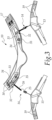
- the apparatus comprises a harness 11 to be worn on the torso of a user 12 and at least one band 13 to be worn around a leg of said user 12, above the knee and without affecting the latter.
- the apparatus 10 is normally provided and used with two bands 13, each one of these to be worn around a respective leg.
- the apparatus 10 comprises a connecting device 14 for connecting the harness 11 with the respective band 13; one device 14 is necessary for each band 13.
- the former in turn, comprises:
- the harness 11 and the bands 13 are provided with adapted closure means, like Velcro ® fasteners 17 and snap-acting buckles 18, for the former, and a system of Velcro ® fasteners 19 for the latter, indicated in Figure 3 , with which it is possible to adjust the width thereof as a function of the size of the torso and of the legs of the user 12.
- Figures 4 and 5 show the innermost side of the harness 11 and of a band 13, with the device 14, designed to be in contact with the body of the user.
- the system of Velcro ® fasteners 19 creates an overlapping of layers on the outermost side and not on the innermost side, in order to render use of the band more comfortable.
- the spring 15 is of the helical type.
- Figures 7 and 8 also show a part of the connection with a band 13.
- the spring 15 is preferably, but not exclusively, of the helical type. It can in fact have an alternative geometry, different from helical.
- the device in all its versions, is adapted to be positioned along the leg of the user, as shown in Figure 1 , for example along the femoral quadriceps.
- the apparatus 10 comprises an insert 20 inside the band 13 with a hole 21 which is open toward the outside of the band 13, in the part directed upward when worn, and accommodating the spring 15, and also comprises a screw plug 22, with a through hole, to be screwed onto the insert 20 at the hole 21.
- the insert can be inside the harness with the hole open toward the outside of the harness, in the part directed downward when worn. Substantially the device, together with the other elements described below, can be installed in the reverse position with respect to what is shown.
- the connecting device 14, 114, 214 comprises a non-extendable cable 23 and passes through the insert 20, the plug 22 and the spring 15, and is connected at one end with the spring 15 and at the other end with the means for pre-tensioning 16.
- the spring 15 can move with respect to the band 13, in compression and in extension, inside the insert 20.
- the apparatus 10 comprises a block 24 at the end of the cable 23 that lies inside the insert 20, which with the plug 22 defines an accommodation space for the spring 15 in the relaxed state.
- the cable 23 extends inside the spring 15.
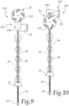
- the means for pre-tensioning 16 comprise a ratchet element, indicated with 25, 125 and 225 in the different variations.
- the ratchet element 25 comprises a buckle with means for opening and release, which are conventional per se, which is coupled to a toothed strip 26 (indicated in Figure 3 ) which extends downward from the harness 11 along the leg, when the apparatus 10 is worn.
- the buckle is coupled to a connecting element 27 to which the cable 23 is joined at the end opposite from the end connected with the spring 15. Also in the first variation, the section of cable 23 comprised between the insert 20 and the connecting element 27 is covered with a sheath 28, which protects the user 12 from direct contact with the cable 23.
- the ratchet element 125 comprises a wheel which is adapted to determine, with its rotation, the winding, one click after another, of the cable 23, in this case too in order to adjust the length of the connection 10 depending on the user and/or as a function of the pre-tensioning requirements.
- the lower part of the device 114 (from the plug downward, with respect to the position of use and with respect to the position shown), for mating with the band 13, is the same as in the previous version.
- a channel-like element 130 and another element 131 with a slot are present, proximate to the wheel, a channel-like element 130 and another element 131 with a slot, the function of which will become clear below.
- the third version of the connecting device 214 differs from the previous one substantially only in that the position of the last two elements cited, here numbered 230 and 231, is in a higher position than the ratchet element 225, i.e. the wheel.
- the apparatus 10 advantageously comprises adjustment means 32, 132, 232 for adjusting the position of the connecting device 14, 114, 214, along the leg of the user 12, for example so that the device is positioned along the femoral quadriceps.
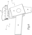
- such adjustment means 32, 132, 232 comprise a guide 33 (indicated in Figure 3 and in Figure 6 ) on the harness 11 on which the connecting device 14, 114, 214 is adapted to slide by way of a channel-like element 30, 130, 230.
- the adjustment means 32, 132, 232 also comprise a tape 34 which is length-adjustable and is coupled to the harness 11 by way of a buckle 35 and is connected at one end to the connecting device 14, 114, 214.
- the part of the adjustment means 32 is shown in Figure 6 , where the guide 33, the channel-like element 31 and the tape 34 are indicated.
- the channel-like element 130, 230 and the element 131 and 231 have a different shape but are connected to the harness 11 in the same way as in the first version.
- the connecting device can comprise a threaded insert and an externally-threaded tubular element, which accommodates the spring, inserted in the insert.
- the tubular element is screwed at one end portion thereof to the plug and at the opposite end portion to the threaded insert.
- the tubular element and the threaded insert are inserted and screwed into the insert mentioned above in the preceding versions and indicated in them with 20.
- the threaded insert is made, preferably, of brass and has a through opening for the spring and the cable. Alternatively, it can be made of other materials, for example of another metallic material or of plastic material.
- This construction variation protects the components subjected to friction and contact during use of the apparatus, like the spring and the cable, from wear.
- the apparatus 10 is evident from the foregoing description and explanation and, in particular, it is evident that it is easily adjustable, in addition to being less cumbersome during use than other conventional apparatuses.
- the apparatus which is easily adjustable, can be worn with the device between the trunk and a portion of leg, above the knee, so that the spring, inside the band, stores energy during the movements of the user, such as during the strides of walking.
- the spring can be compressed and return to the relaxed or pretensioned state, releasing the energy stored in order to assist the flexion and extension of the leg.
- the invention fully achieves the intended aim and objects by providing an apparatus that is comfortable to wear and to adjust, even during the performance of activities by the user, not particularly cumbersome even under clothing and at the same time capable of ensuring the correct release of energy during walking, as a function of the requirements of the user.
Landscapes
- Health & Medical Sciences (AREA)
- Epidemiology (AREA)
- Pain & Pain Management (AREA)
- Physical Education & Sports Medicine (AREA)
- Rehabilitation Therapy (AREA)
- Life Sciences & Earth Sciences (AREA)
- Animal Behavior & Ethology (AREA)
- General Health & Medical Sciences (AREA)
- Public Health (AREA)
- Veterinary Medicine (AREA)
- Rehabilitation Tools (AREA)
Claims (9)
- Eine Vorrichtung (10) für unterstützte Mobilität, die Folgendes umfasst: ein Korsett (11), zu tragen am Torso eines Benutzers (12), mindestens eine Bandage (13), zu tragen um ein Bein des Benutzers (12) oberhalb des Knies und eine Verbindungsvorrichtung (14, 114, 214) zum Verbinden des Korsetts (11) mit der mindestens einen Bandage (13), die wiederum Folgendes umfasst:- mindestens eine Feder (15), ausgebildet, um von einem entspannten Zustand oder von einem ersten Spannungszustand während des Gehens oder während anderer Bewegungen des Benutzers in einen zweiten Spannungszustand zu wechseln, und- Mittel (16) zum Vorspannen der Feder (15),wobei die Vorrichtung (10) dadurch gekennzeichnet ist, dass sie einen Einsatz (20) in dem Korsett (11) und/oder der Bandage (13) umfasst, mit einem Loch (21), welches zumindest zur Außenseite des Korsetts (11) oder der Bandage (13) hin offen ist und die Feder (15) aufnimmt, und einer Verschlussschraube (22) mit einem Durchgangsloch, aufgeschraubt auf den Einsatz (20) an dem Loch (21),wobei die Verbindungsvorrichtung (14, 114, 214) ein Kabel (23) umfasst, das durch den Einsatz (20) und die Verschlussschraube (22) verläuft und an einem Ende mit der Feder (15) und am gegenüberliegenden Ende mit den Mitteln (16) zum Vorspannen der Feder (15) verbunden ist.
- Die Vorrichtung (10) gemäß Anspruch 1, dadurch gekennzeichnet, dass die Feder (15) vom Spiraltyp ist.
- Die Vorrichtung (10) gemäß einem oder mehreren der obigen Ansprüche, dadurch gekennzeichnet, dass sie einen Block (24) am Ende des Kabels (23) umfasst, mit welchem die Verschlussschraube (22) einen Aufnahmeraum für die Feder (15) im entspannten Zustand bestimmt, wobei das Kabel (23) sich in der Feder (15) erstreckt.
- Die Vorrichtung (10) gemäß einem oder mehreren der obigen Ansprüche, dadurch gekennzeichnet, dass die Mittel (16) zum Vorspannen ein Ratschenelement (25, 125, 225) umfassen.
- Die Vorrichtung (10) gemäß einem oder mehreren der obigen Ansprüche, dadurch gekennzeichnet, dass sie Anpassungsmittel (32, 132, 232) zur Anpassung der Position der Verbindungsvorrichtung (14, 114, 214) entlang dem Bein des Benutzers (12) umfasst, die eine Führung (33) auf dem Korsett (11) umfassen und auf denen die Verbindungsvorrichtung (14, 114, 214) ausgebildet ist, um mit Hilfe eines kanalähnlichen Elements (30, 130, 230) zu gleiten.
- Die Vorrichtung (10) gemäß einem oder mehreren der obigen Ansprüche, dadurch gekennzeichnet, dass die Anpassungsmittel (32, 132, 232) ein Band (34) umfassen, das in der Länge verstellbar ist, mit Hilfe einer Schnalle (35) mit dem Korsett (11) gekoppelt wird und an einem Ende mit der Verbindungsvorrichtung (14, 114, 214) verbunden ist.
- Die Vorrichtung (10) gemäß einem oder mehreren der obigen Ansprüche, dadurch gekennzeichnet, dass das Ratschenelement (25) eine Schnalle umfasst.
- Die Vorrichtung (10) gemäß einem oder mehreren der obigen Ansprüche, dadurch gekennzeichnet, dass das Ratschenelement (125, 225) ein Rad umfasst.
- Die Vorrichtung (10) gemäß einem oder mehreren der obigen Ansprüche, dadurch gekennzeichnet, dass die Verbindungsvorrichtung (14, 114, 214) einen mit einem Gewinde versehenen Einsatz und ein rohrförmiges Element umfasst, die in den Einsatz (20) eingeführt werden, wobei das rohrförmige Element die Feder (15) aufnimmt.
Applications Claiming Priority (2)
| Application Number | Priority Date | Filing Date | Title |
|---|---|---|---|
| IT202000026362 | 2020-11-05 | ||
| PCT/EP2021/080605 WO2022096555A1 (en) | 2020-11-05 | 2021-11-04 | Apparatus for assisted mobility |
Publications (3)
| Publication Number | Publication Date |
|---|---|
| EP4236901A1 EP4236901A1 (de) | 2023-09-06 |
| EP4236901B1 true EP4236901B1 (de) | 2024-12-04 |
| EP4236901C0 EP4236901C0 (de) | 2024-12-04 |
Family
ID=74347517
Family Applications (1)
| Application Number | Title | Priority Date | Filing Date |
|---|---|---|---|
| EP21802361.2A Active EP4236901B1 (de) | 2020-11-05 | 2021-11-04 | Vorrichtung für unterstützte mobilität |
Country Status (3)
| Country | Link |
|---|---|
| US (1) | US20230404836A1 (de) |
| EP (1) | EP4236901B1 (de) |
| WO (1) | WO2022096555A1 (de) |
Families Citing this family (1)
| Publication number | Priority date | Publication date | Assignee | Title |
|---|---|---|---|---|
| KR102754295B1 (ko) * | 2022-11-23 | 2025-01-14 | 주식회사 이온메드 | 장력조절이 용이한 웨어러블 재활 보조 장치 |
Family Cites Families (14)
| Publication number | Priority date | Publication date | Assignee | Title |
|---|---|---|---|---|
| US2772674A (en) * | 1953-11-25 | 1956-12-04 | Swiech Edward | Orthopedic torsion leg brace |
| US4524760A (en) * | 1983-05-31 | 1985-06-25 | Elaine Lerner | Sexual aid |
| US5308305A (en) * | 1991-03-19 | 1994-05-03 | Jan W. Romney | Device to augment exercise |
| RU2054907C1 (ru) * | 1992-01-31 | 1996-02-27 | Акционерное Общество Закрытого Типа "Аюрведа" | Устройство для лечения больных с нарушением позы и двигательной активности |
| US5993362A (en) * | 1998-06-03 | 1999-11-30 | Ghobadi; Arthur Soroush | Martial arts conditioning device |
| US6428495B1 (en) * | 1999-10-22 | 2002-08-06 | John P. Lynott | Hamstring brace |
| US7476185B2 (en) * | 2002-09-04 | 2009-01-13 | Denis Burke Drennan | Dynamic hip stabilizer |
| US7600660B2 (en) * | 2004-03-11 | 2009-10-13 | Raymond Nevin Kasper | Harness tightening system |
| US9186536B2 (en) * | 2012-12-17 | 2015-11-17 | Kenneth L. Strachan | Training device |
| EP3777677B1 (de) * | 2013-05-31 | 2024-11-06 | President And Fellows Of Harvard College | Wiches exoskelett zur unterstützung von menshlicher bewegung |
| US20190030708A1 (en) * | 2016-10-03 | 2019-01-31 | Springactive, Inc. | Personal Augmentation Suit and Method for Assisted Human Motion |
| US11116654B2 (en) * | 2018-02-26 | 2021-09-14 | Stand Strong Company LLC | Device and method for reinforcing the lower body during the performance of a compound weightlifting exercise |
| JP2021528174A (ja) * | 2018-06-18 | 2021-10-21 | モべオ・ソシエタ・ア・レスポンサビリタ・リミタータMoveo Srl | 移動補助のためのシステムおよび装置 |
| KR102752450B1 (ko) * | 2019-11-01 | 2025-01-15 | 삼성전자주식회사 | 허벅지 형상에 기초하여 변형 가능한 보행 보조 장치 |
-
2021
- 2021-11-04 EP EP21802361.2A patent/EP4236901B1/de active Active
- 2021-11-04 US US18/251,843 patent/US20230404836A1/en active Pending
- 2021-11-04 WO PCT/EP2021/080605 patent/WO2022096555A1/en not_active Ceased
Also Published As
| Publication number | Publication date |
|---|---|
| EP4236901A1 (de) | 2023-09-06 |
| EP4236901C0 (de) | 2024-12-04 |
| WO2022096555A1 (en) | 2022-05-12 |
| US20230404836A1 (en) | 2023-12-21 |
| CN116546951A (zh) | 2023-08-04 |
Similar Documents
| Publication | Publication Date | Title |
|---|---|---|
| EP3806807B1 (de) | Systeme und vorrichtungen zur unterstützenden mobilität | |
| US10806966B2 (en) | Motion assistance apparatus | |
| US12558774B2 (en) | Soft exosuit for assistance with human motion | |
| US9788985B2 (en) | Friction-based orthotic impedence modulation device | |
| EP2649976B1 (de) | Vorrichtung zur unterstützung von gelenkübungen | |
| US9763847B2 (en) | Walking movement aid | |
| US10524973B2 (en) | Movement assistance device | |
| US8235924B2 (en) | Orthotic brace | |
| WO2017026943A1 (en) | Exosuit | |
| CN114980842A (zh) | 关节运动辅助装置 | |
| KR101664351B1 (ko) | 복부 자동압박복대 | |
| US10835407B2 (en) | Orthotic device for assisting limb movement | |
| US20110009788A1 (en) | Orthotic Device with Removably Attachable Actuator | |
| KR20150134889A (ko) | 지지 모듈 및 이를 포함하는 운동 보조 장치 | |
| US20140259798A1 (en) | Systems and Methods for Gravitational Load Support | |
| EP4236901B1 (de) | Vorrichtung für unterstützte mobilität | |
| CN116546951B (zh) | 用于辅助行动的设备 | |
| CN118617383A (zh) | 一种用于矿工负重行走助力的下肢外骨骼系统 | |
| CN117260678A (zh) | 一种连接件及其应用的关节外骨骼及膝关节外骨骼 | |
| CA3103434C (en) | Systems and devices with elastically deformable members for assistive mobility | |
| KR102568519B1 (ko) | 근력 보조 로봇용 레그 프레임 | |
| CN121535713A (zh) | 一种基于鲍登线驱动结构的膝关节助力外骨骼 |
Legal Events
| Date | Code | Title | Description |
|---|---|---|---|
| STAA | Information on the status of an ep patent application or granted ep patent |
Free format text: STATUS: UNKNOWN |
|
| STAA | Information on the status of an ep patent application or granted ep patent |
Free format text: STATUS: THE INTERNATIONAL PUBLICATION HAS BEEN MADE |
|
| PUAI | Public reference made under article 153(3) epc to a published international application that has entered the european phase |
Free format text: ORIGINAL CODE: 0009012 |
|
| STAA | Information on the status of an ep patent application or granted ep patent |
Free format text: STATUS: REQUEST FOR EXAMINATION WAS MADE |
|
| 17P | Request for examination filed |
Effective date: 20230601 |
|
| AK | Designated contracting states |
Kind code of ref document: A1 Designated state(s): AL AT BE BG CH CY CZ DE DK EE ES FI FR GB GR HR HU IE IS IT LI LT LU LV MC MK MT NL NO PL PT RO RS SE SI SK SM TR |
|
| DAV | Request for validation of the european patent (deleted) | ||
| DAX | Request for extension of the european patent (deleted) | ||
| GRAP | Despatch of communication of intention to grant a patent |
Free format text: ORIGINAL CODE: EPIDOSNIGR1 |
|
| STAA | Information on the status of an ep patent application or granted ep patent |
Free format text: STATUS: GRANT OF PATENT IS INTENDED |
|
| INTG | Intention to grant announced |
Effective date: 20240701 |
|
| GRAS | Grant fee paid |
Free format text: ORIGINAL CODE: EPIDOSNIGR3 |
|
| GRAA | (expected) grant |
Free format text: ORIGINAL CODE: 0009210 |
|
| STAA | Information on the status of an ep patent application or granted ep patent |
Free format text: STATUS: THE PATENT HAS BEEN GRANTED |
|
| AK | Designated contracting states |
Kind code of ref document: B1 Designated state(s): AL AT BE BG CH CY CZ DE DK EE ES FI FR GB GR HR HU IE IS IT LI LT LU LV MC MK MT NL NO PL PT RO RS SE SI SK SM TR |
|
| REG | Reference to a national code |
Ref country code: CH Ref legal event code: EP |
|
| REG | Reference to a national code |
Ref country code: DE Ref legal event code: R096 Ref document number: 602021023000 Country of ref document: DE |
|
| REG | Reference to a national code |
Ref country code: IE Ref legal event code: FG4D |
|
| U01 | Request for unitary effect filed |
Effective date: 20241231 |
|
| U07 | Unitary effect registered |
Designated state(s): AT BE BG DE DK EE FI FR IT LT LU LV MT NL PT RO SE SI Effective date: 20250114 |
|
| PG25 | Lapsed in a contracting state [announced via postgrant information from national office to epo] |
Ref country code: HR Free format text: LAPSE BECAUSE OF FAILURE TO SUBMIT A TRANSLATION OF THE DESCRIPTION OR TO PAY THE FEE WITHIN THE PRESCRIBED TIME-LIMIT Effective date: 20241204 |
|
| PG25 | Lapsed in a contracting state [announced via postgrant information from national office to epo] |
Ref country code: ES Free format text: LAPSE BECAUSE OF FAILURE TO SUBMIT A TRANSLATION OF THE DESCRIPTION OR TO PAY THE FEE WITHIN THE PRESCRIBED TIME-LIMIT Effective date: 20241204 |
|
| PG25 | Lapsed in a contracting state [announced via postgrant information from national office to epo] |
Ref country code: NO Free format text: LAPSE BECAUSE OF FAILURE TO SUBMIT A TRANSLATION OF THE DESCRIPTION OR TO PAY THE FEE WITHIN THE PRESCRIBED TIME-LIMIT Effective date: 20250304 |
|
| PG25 | Lapsed in a contracting state [announced via postgrant information from national office to epo] |
Ref country code: GR Free format text: LAPSE BECAUSE OF FAILURE TO SUBMIT A TRANSLATION OF THE DESCRIPTION OR TO PAY THE FEE WITHIN THE PRESCRIBED TIME-LIMIT Effective date: 20250305 |
|
| PG25 | Lapsed in a contracting state [announced via postgrant information from national office to epo] |
Ref country code: RS Free format text: LAPSE BECAUSE OF FAILURE TO SUBMIT A TRANSLATION OF THE DESCRIPTION OR TO PAY THE FEE WITHIN THE PRESCRIBED TIME-LIMIT Effective date: 20250304 |
|
| PG25 | Lapsed in a contracting state [announced via postgrant information from national office to epo] |
Ref country code: SM Free format text: LAPSE BECAUSE OF FAILURE TO SUBMIT A TRANSLATION OF THE DESCRIPTION OR TO PAY THE FEE WITHIN THE PRESCRIBED TIME-LIMIT Effective date: 20241204 |
|
| PG25 | Lapsed in a contracting state [announced via postgrant information from national office to epo] |
Ref country code: PL Free format text: LAPSE BECAUSE OF FAILURE TO SUBMIT A TRANSLATION OF THE DESCRIPTION OR TO PAY THE FEE WITHIN THE PRESCRIBED TIME-LIMIT Effective date: 20241204 |
|
| PG25 | Lapsed in a contracting state [announced via postgrant information from national office to epo] |
Ref country code: IS Free format text: LAPSE BECAUSE OF FAILURE TO SUBMIT A TRANSLATION OF THE DESCRIPTION OR TO PAY THE FEE WITHIN THE PRESCRIBED TIME-LIMIT Effective date: 20250404 |
|
| PG25 | Lapsed in a contracting state [announced via postgrant information from national office to epo] |
Ref country code: SK Free format text: LAPSE BECAUSE OF FAILURE TO SUBMIT A TRANSLATION OF THE DESCRIPTION OR TO PAY THE FEE WITHIN THE PRESCRIBED TIME-LIMIT Effective date: 20241204 |
|
| PG25 | Lapsed in a contracting state [announced via postgrant information from national office to epo] |
Ref country code: CZ Free format text: LAPSE BECAUSE OF FAILURE TO SUBMIT A TRANSLATION OF THE DESCRIPTION OR TO PAY THE FEE WITHIN THE PRESCRIBED TIME-LIMIT Effective date: 20241204 |
|
| PLBE | No opposition filed within time limit |
Free format text: ORIGINAL CODE: 0009261 |
|
| STAA | Information on the status of an ep patent application or granted ep patent |
Free format text: STATUS: NO OPPOSITION FILED WITHIN TIME LIMIT |
|
| 26N | No opposition filed |
Effective date: 20250905 |
|
| U20 | Renewal fee for the european patent with unitary effect paid |
Year of fee payment: 5 Effective date: 20251120 |
|
| PGFP | Annual fee paid to national office [announced via postgrant information from national office to epo] |
Ref country code: GB Payment date: 20251118 Year of fee payment: 5 |