EP4236573B1 - Datenübertragungsverfahren und geräte - Google Patents
Datenübertragungsverfahren und geräte Download PDFInfo
- Publication number
- EP4236573B1 EP4236573B1 EP21916774.9A EP21916774A EP4236573B1 EP 4236573 B1 EP4236573 B1 EP 4236573B1 EP 21916774 A EP21916774 A EP 21916774A EP 4236573 B1 EP4236573 B1 EP 4236573B1
- Authority
- EP
- European Patent Office
- Prior art keywords
- bwp
- initial
- terminal device
- coreset
- scheduling
- Prior art date
- Legal status (The legal status is an assumption and is not a legal conclusion. Google has not performed a legal analysis and makes no representation as to the accuracy of the status listed.)
- Active
Links
Images


Classifications
-
- H—ELECTRICITY
- H04—ELECTRIC COMMUNICATION TECHNIQUE
- H04W—WIRELESS COMMUNICATION NETWORKS
- H04W72/00—Local resource management
- H04W72/12—Wireless traffic scheduling
- H04W72/1263—Mapping of traffic onto schedule, e.g. scheduled allocation or multiplexing of flows
- H04W72/1268—Mapping of traffic onto schedule, e.g. scheduled allocation or multiplexing of flows of uplink data flows
-
- H—ELECTRICITY
- H04—ELECTRIC COMMUNICATION TECHNIQUE
- H04W—WIRELESS COMMUNICATION NETWORKS
- H04W74/00—Wireless channel access
- H04W74/08—Non-scheduled access, e.g. ALOHA
- H04W74/0833—Random access procedures, e.g. with 4-step access
-
- H—ELECTRICITY
- H04—ELECTRIC COMMUNICATION TECHNIQUE
- H04W—WIRELESS COMMUNICATION NETWORKS
- H04W74/00—Wireless channel access
- H04W74/08—Non-scheduled access, e.g. ALOHA
- H04W74/0833—Random access procedures, e.g. with 4-step access
- H04W74/0836—Random access procedures, e.g. with 4-step access with 2-step access
Definitions
- This disclosure relates to the field of wireless communication, and particularly to methods and devices for data transmission.
- a radio resource control (RRC)_INACTIVE state (namely, an inactive state) is a new RRC state introduced in a new radio (NR) system from the perspective of power saving.
- Small data transmission is introduced in release 17 (R17), and an SDT procedure corresponding to the SDT is a data transmission procedure in the inactive state.
- SDT procedure a terminal device does not have to enter an RRC_CONNECTED state (namely, a connected state), and can complete data transmission in the inactive state, which can reduce power consumption and overhead of the terminal device.
- RACH configuration for small data transmission 3GPP Draft, R2-2009097 relates to "RACH configuration for Small Data Transmission", which has the following options: "Option 1: RACH based SDT is always performed on initial BWP, Option 2: The BWP for RACH based SDT is configurable.”
- Implementations of the disclosure provide methods and devices for data transmission.
- a terminal device can perform a random access channel (RACH)-based small data transmission (SDT) procedure on a target bandwidth determined.
- RACH random access channel
- SDT small data transmission
- the terminal device firstly determines the target bandwidth before performing the RACH-based SDT procedure, and then performs the RACH-based SDT procedure on the target bandwidth, which provides a way for determining a bandwidth used for performing an SDT procedure.
- Radio resource control (RRC) state
- NR new radio
- RRC_INACTIVE new radio
- RRC_INACTIVE state Mobility is based on cell selection and reselection of a terminal device. There is a connection between a core network (CN) and NR. A user equipment (UE) access context exists in a network device. Paging is triggered by a radio access network (RAN), a RAN-based paging area is managed by the RAN, and the network device knows that a location of the terminal device is based on a RAN-based paging area level.
- RAN radio access network
- RAN-based paging area is managed by the RAN, and the network device knows that a location of the terminal device is based on a RAN-based paging area level.
- BWP is a concept introduced in NR.
- BWP is defined as an access bandwidth smaller than each of a system bandwidth of a cell and a terminal capability, and all reception and transmission operations of the terminal device can be performed on the small bandwidth, thereby realizing a terminal operation with higher flexibility, higher efficiency, and lower power consumption.
- the terminal device can flexibly select among BWPs with different bandwidths according to service requirements.
- the terminal device In a downlink (DL) direction, the terminal device is configured with up to four DL BWPs, and only one DL BWP can be activated at one time, where the terminal device can receive a DL channel on the activated DL BWP.
- DL downlink
- UL uplink
- the terminal device In an uplink (UL) direction, the terminal device is configured with up to four UL BWPs, and only one UL BWP can be activated at one time, where the terminal device can receive an UL channel on the activated UL BWP.
- the terminal device can be additionally configured with four UL BWPs, and only one UL BWP can be activated at one time, where the terminal device can receive an UL channel on the activated UL BWP.
- SUL supplementary uplink
- each DL BWP at least has one control resource set (CORESET), where the CORESET is used for physical downlink control channel (PDCCH) reception and detection, i.e., the CORESET is a time-frequency range for the terminal device to search for a PDCCH.
- CORESET control resource set
- a CORESET can occupy consecutive or nonconsecutive frequency-domain resources.
- the network device can indicate, via a bitmap in RRC signaling, a physical resource block (PRB) occupied by the CORESET in the DL BWP, where each bit in the bitmap indicates a resource block (RB) group containing six RBs.
- PRB physical resource block
- a duration parameter in a CORESET configuration is used for indicating a time-domain length of the CORESET. Since the CORESET itself does not have time location information, the CORESET defines a time-domain region which is not fixed and can float in time location and is determined by the duration parameter. Therefore, the network device needs to configure a search space to further indicate a time-domain region in which the terminal device can receive a PDCCH.
- the UL BWP and the DL BWP above are terminal-dedicated BWPs (namely, UE-dedicated BWPs) configured by using dedicated RRC signaling.
- the terminal device is further configured with an initial UL BWP and an initial DL BWP. Before entering the connected state, the terminal device operates on the initial UL BWP or the initial DL BWP.
- An initial UL BWP is configured in a system information block 1 (SIB1), and on the initial UL BWP, the terminal device completes transmission of a preamble, a message 3 (Msg3), or a message A (MsgA) during an initial random access procedure.
- SIB1 system information block 1
- Msg3 message 3
- MsgA message A
- the initial DL BWP has a CORESET#0, where the CORESET#0 is used for scheduling an SIB1, other system information (OSI), or physical downlink shared channel (PDSCH) information in an initial random access procedure such as message 2 (Msg2) or message 4 (Msg4).
- SIB1 system information
- OSI system information
- PDSCH physical downlink shared channel
- a method for the terminal device to determine a CORESET#0 in an initial DL BWP is as follows.
- the terminal device After cell search is completed, the terminal device obtains a synchronization signal block (SSB) from a network-device side, determines a frequency-domain location of the SSB, then determines, based on a physical broadcast channel (PBCH) in the SSB, a frequency offset value of a CORESET#0 relative to the SSB, and thus determines the CORESET#0 based on the frequency location of the SSB and the frequency offset value of the CORESET#0 relative to the SSB.
- PBCH physical broadcast channel
- Two ways for determining the initial DL BWP are supported in the standard.
- the terminal device takes a frequency domain range of the CORESET#0 as a bandwidth of the initial DL BWP.
- the initial DL BWP is configured by higher-layer signaling (for example, SIB1)
- the initial DL BWP is determined according to a configuration of the higher-layer signaling.
- the terminal device receives, on a CORESET#0, a DL message transmitted by the network device, such as a random access response (RAR), a contention resolution message, and an RRC setup message (namely, RRCSetup) or an RRC release message (namely, RRCRelease) or an RRC reestablishment message (namely, RRCReestablishment).
- RAR random access response
- RRC setup message namely, RRCSetup
- RRC release message namely, RRCRelease
- RRCReestablishment message namely, RRCReestablishment
- SDT is a data transmission mode configured for the terminal device in the inactive state.
- the terminal device can complete data transmission without entering the connected state, thereby reducing power consumption and overhead of the terminal device.
- the SDT procedure includes a configured grant (CG)-based SDT procedure and a random access channel (RACH)-based SDT procedure.
- CG configured grant
- RACH random access channel
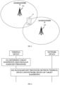
- FIG. 3 is a block diagram of a communication system provided in an exemplary implementation of the disclosure.
- the communication system may include an access network 12 and a terminal device 14.
- the access network 12 includes multiple network devices 120.
- the network device 120 can be a base station.
- the base station is an apparatus that is deployed in the access network and used to provide wireless communication functions for the terminal.
- the base station can include various forms of macro base stations, micro base stations, relay stations, access points, etc.
- a device with functions of the base station may be in different names.
- LTE long-term evolution
- eNodeB eNodeB
- gNodeB 5 th generation
- gNodeB 5 th generation
- the term "base station” may change.
- the devices that can provide wireless communication functions for the terminal device 14 are collectively referred to as "network device".
- the terminal device 14 can include various devices with wireless communication functions such as handheld devices, in-vehicle devices, wearable devices, computing devices, or other processing devices connected to a wireless modem, as well as various forms of UEs, mobile stations (MS), terminal devices, etc.
- terminal the above devices are collectively referred to as "terminal".
- the network device 120 and the terminal device 14 can communicate with each other with aid of an air-interface technology, such as a UE-universal mobile telecommunication system (UMTS) terrestrial radio access network (UE-UTRAN, Uu) interface.
- UMTS UE-universal mobile telecommunication system
- UE-UTRAN Universal Terrestriality
- GSM global system of mobile communication
- CDMA code division multiple access
- WCDMA wideband code division multiple access
- GPRS general packet radio service
- LTE LTE system
- FDD frequency division duplex
- TDD time division duplex
- LTE-A advanced LTE
- NR NR system
- UMTS universal mobile telecommunication system
- WiMAX worldwide interoperability for microwave access
- WLAN wireless local area network
- WiFi wireless fidelity
- next-generation communication system or other communication systems.
- a conventional communication system generally supports a limited quantity of connections and therefore is easy to implement.
- a mobile communication system will not only support conventional communication but also support, for example, device to device (D2D) communication, machine to machine (M2M) communication, machine type communication (MTC), vehicle to vehicle (V2V) communication, or vehicle to everything (V2X) system, etc. Implementations of the disclosure can also be applied to these communication systems.
- D2D device to device
- M2M machine to machine
- MTC machine type communication
- V2V vehicle to vehicle
- V2X vehicle to everything
- FIG. 4 is a flowchart of a method for data transmission provided in an exemplary implementation of the disclosure. The method can be applied to the communication system illustrated in FIG. 3 . The method includes the following.
- Step 410 a terminal device determines a target bandwidth used for a RACH-based SDT procedure.
- the terminal device Before performing the RACH-based SDT procedure, the terminal device determines the target bandwidth used for the RACH-based SDT procedure.
- the target bandwidth includes a target bandwidth used for UL and a target bandwidth used for DL.
- the terminal device can determine, according to a configuration of the higher-layer signaling, the target bandwidth used for the RACH-based SDT procedure.
- the SDT procedure is a data transmission procedure in an inactive state of the terminal device.
- SDT is a data transmission mode configured for the terminal device in the inactive state, and there is no need for RRC connection establishment between the terminal device and the network device.
- the terminal device For a terminal device with low data volume and low transmission frequency, if data transmission is performed only after an RRC connection with the network device is resumed through a connection resume procedure, the terminal device needs to return to the inactive state after data transmission is completed, and as a result, power consumption of the terminal device will be high.
- the terminal device can be exempt from RRC state transition, thereby reducing power consumption of the terminal device.
- the SDT procedure includes a CG-based SDT procedure and a RACH-based SDT procedure.
- the RACH-based SDT procedure is taken as an example.
- the RACH-based SDT procedure may be a 2-step RACH-based SDT procedure, or may be a 4-step RACH-based SDT procedure, and implementations of the disclosure are not limited in this regard.
- Step 420 the terminal device performs the RACH-based SDT procedure with the network device on the target bandwidth.
- the terminal device After determining the target bandwidth, the terminal device perform the RACH-based SDT procedure with the network device on the target bandwidth.
- the target bandwidth includes a target bandwidth used for UL and a target bandwidth used for DL.
- the terminal device performs UL transmission on the target bandwidth used for UL, and the network device performs UL reception on the target bandwidth used for UL.
- the terminal device performs DL reception on the target bandwidth used for DL, and the network device performs DL transmission on the target bandwidth used for DL.
- the terminal device firstly determines the target bandwidth before performing the RACH-based SDT procedure, and then performs the RACH-based SDT procedure on the target bandwidth, which provides a way for determining a bandwidth used for performing an SDT procedure.
- the initial UL BWP and the initial DL BWP are operation bandwidths determined by the terminal device during an initial access procedure.
- the terminal device determines the initial UL BWP and the initial DL BWP during the initial access procedure, and performs the RACH-based SDT procedure with the network device on the initial UL BWP and the initial DL BWP.
- the target bandwidth includes a first UL BWP and a first DL BWP.
- the first UL BWP and the first DL BWP are BWPs configured for the terminal device and dedicated for the RACH-based SDT procedure.
- the first UL BWP and the first DL BWP are introduced for the RACH-based SDT procedure, and the terminal device performs the RACH-based SDT procedure with the network device on the first UL BWP and the first DL BWP that are newly introduced.
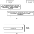
- FIG. 5 is a flowchart of a method for data transmission provided in an exemplary implementation of the disclosure.
- the method can be applied to the communication system illustrated in FIG. 3 .
- the method includes the following.
- Step 510 the terminal device determines the initial UL BWP and the initial DL BWP as the target bandwidth, where the initial DL BWP has a CORESET#0.
- the initial UL BWP and the initial DL BWP are operation bandwidths determined by the terminal device during an initial access procedure.
- the CORESET#0 is a control resource set used for carrying scheduling information of SIB1(where SIB1 is also referred to as remaining minimum system information (RMSI)). As illustrated in FIG. 6 , the initial DL BWP has the CORESET#0.
- the initial UL BWP and the initial DL BWP are determined based on an SIB 1 scheduled by the CORESET#0. That is, after determining the CORESET#0, the terminal device receives the SIB1 scheduled by the CORESET#0, and determines the initial UL BWP and the initial DL BWP based on the SIB1.
- the terminal device determines the CORESET#0 as follows. After cell search is completed, the terminal device obtains an SSB from a network-device side, determines a frequency-domain location of the SSB, then determines, based on a PBCH in the SSB, a frequency offset value of the CORESET#0 relative to the SSB, and thus determines the CORESET#0 based on the frequency location of the SSB and the frequency offset value of the CORESET#0 relative to the SSB.
- Step 520 the terminal device performs the RACH-based SDT procedure with the network device on the target bandwidth.
- the RACH-based SDT comprises a 4-step RACH-based STD.
- the RACH-based SDT procedure includes a 4-step RACH-based SDT procedure and a 2-step RACH-based SDT procedure.
- the terminal device transmits to the network device on the initial UL BWP at least one of a preamble, a Msg3, a Msg3 retransmission, or an UL transmission dynamically scheduled by the network device. Accordingly, the network device receives, on the initial UL BWP, at least one of the preamble, the Msg3, the Msg3 retransmission, or the UL transmission dynamically scheduled by the network device transmitted by the terminal device.
- the terminal device receives, on the CORESET#0 in the initial DL BWP, at least one of an RAR, a Msg3 retransmission indication, or a Msg4. Accordingly, the network device transmits to the terminal device on the CORESET#0 in the initial DL BWP at least one of the RAR, the Msg3 retransmission indication, or the Msg4.
- the terminal device stays in the inactive state, and the terminal device and the network device can perform continuous UL transmission or DL transmission.
- the bandwidth can be switched from the CORESET#0 to a larger bandwidth.
- the terminal device receives a resource scheduling on the initial DL BWP, where the resource scheduling includes at least one of an UL scheduling or a DL scheduling. Accordingly, if the Msg4 includes the contention resolution message and does not include the RRC release message, the network device transmits the resource scheduling on the initial DL BWP, where the resource scheduling includes at least one of the UL scheduling or the DL scheduling.
- the terminal device switches from the CORESET#0 to the initial DL BWP with a larger bandwidth, so as to receive a subsequent resource scheduling.
- the initial DL BWP further has a first CORESET and/or a first search space, where the first CORESET is a CORESET configured for the terminal device in the initial DL BWP, and the first search space is a search space configured for the terminal device in the initial DL BWP.
- the terminal device receives a resource scheduling on the first CORESET and/or the first search space, where the resource scheduling includes at least one of an UL scheduling or a DL scheduling. Accordingly, if the Msg4 includes the contention resolution message and does not include the RRC release message, the network device transmits the resource scheduling on the first CORESET and/or the first search space, where the resource scheduling includes at least one of the UL scheduling or the DL scheduling.
- the network device configures for the terminal device the first CORESET dedicated for the SDT procedure, or the network device configures for the terminal device the first search space dedicated for the SDT procedure, or the network device configures for the terminal device the first CORESET and the first search space dedicated for the SDT procedure. If the Msg4 indicates that contention resolution has been completed and does not indicate termination of the SDT procedure, the terminal device switches from the CORESET#0 to the first CORESET and/or the first search space with a larger bandwidth, so as to receive a subsequent resource scheduling.
- the first CORESET and/or the first search space is determined based on the SIB1 scheduled by the CORESET#0.
- the terminal device receives the SIB1 scheduled by the CORESET#0, and determines the first CORESET, or the first search space, or both the first CORESET and the first search space according to the SIB1 in addition to determining the initial UL BWP and the initial DL BWP according to the SIB 1.
- the UL scheduling and the DL scheduling belong to the same RACH-based SDT procedure.
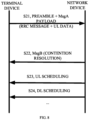
- the 4-step RACH-based SDT procedure between the terminal device and the network device includes the following.
- the terminal device transmits a preamble on the initial UL BWP.
- the network device receives the preamble on the initial UL BWP.
- the network device transmits an RAR on the CORESET#0.
- the terminal device receives the RAR on the CORESET#0.
- the terminal device transmits a Msg3 on the initial UL BWP.
- the network device receives the Msg3 on the initial UL BWP.
- the Msg3 includes an RRC message and UL data.
- the network device transmits a Msg4 on the CORESET#0.
- the terminal device receives the Msg4 on the CORESET#0.
- the Msg4 includes a contention resolution message, but does not include an RRC release message.
- the network device transmits an UL scheduling on the initial DL BWP.
- the terminal device receives the UL scheduling on the initial DL BWP.
- the network device transmits the UL scheduling on the first CORESET and/or the first search space. Accordingly, the terminal device receives the UL scheduling on the first CORESET and/or the first search space.
- the network device transmits a DL scheduling on the initial DL BWP.
- the terminal device receives the DL scheduling on the initial DL BWP.
- the network device transmits the DL scheduling on the first CORESET and/or the first search space. Accordingly, the terminal device receives the DL scheduling on the first CORESET and/or the first search space.
- the terminal device performs a 2-step RACH-based SDT procedure with the network device on the target bandwidth.
- the terminal device transmits to the network device on the initial UL BWP at least one of a preamble, a MsgA payload, a Msg3, a Msg3 retransmission, or an UL transmission dynamically scheduled by the network device. Accordingly, the network device receives, on the initial UL BWP, at least one of the preamble, the MsgA payload, the Msg3, the Msg3 retransmission, or the UL transmission dynamically scheduled by the network device transmitted by the terminal device.
- the terminal device receives, on the CORESET#0 in the initial DL BWP, at least one of an RAR, a Msg3 retransmission indication, a Msg4, or a message B (MsgB) transmitted by the network device. Accordingly, the network device transmits to the terminal device on the CORESET#0 in the initial DL BWP at least one of the RAR, the Msg3 retransmission indication, the Msg4, or the MsgB.
- the network device will transmit the RAR to the terminal device. After receiving the RAR, the terminal device transmits the Msg3 to the network device. If the network device successfully receives the Msg3, the network device will feed back the Msg4 to the terminal device. If the network device successfully receives the preamble and the MsgA payload transmitted by the terminal device, the network device will feed back the MsgB to the terminal device. After transmission of the Msg4 or the MsgB is completed, the terminal device stays in the inactive state, and the terminal device and the network device can perform continuous UL transmission or DL transmission. In order to receive an UL scheduling or a DL scheduling required for the continuous UL transmission or DL transmission, the bandwidth can be switched from the CORESET#0 to a larger bandwidth.
- the terminal device receives a resource scheduling on the initial DL BWP, where the resource scheduling includes at least one of an UL scheduling or a DL scheduling.
- the terminal device receives a resource scheduling on the initial DL BWP, where the resource scheduling includes at least one of an UL scheduling or a DL scheduling.
- the network device transmits the resource scheduling on the initial DL BWP, where the resource scheduling includes at least one of the UL scheduling or the DL scheduling.
- the Msg4 includes the contention resolution message and does not include the RRC release message
- the network device transmits the resource scheduling on the initial DL BWP, where the resource scheduling includes at least one of the UL scheduling or the DL scheduling.
- the Msg4 includes the contention resolution message and does not include the RRC release message
- the network device transmits the resource scheduling on the initial DL BWP, where the resource scheduling includes at least one of the UL scheduling or the DL scheduling.
- the terminal device switches from the CORESET#0 to the initial DL BWP with a larger bandwidth, so as to receive a subsequent resource scheduling.
- the initial DL BWP further has a first CORESET and/or a first search space, where the first CORESET is a CORESET configured for the terminal device in the initial DL BWP, and the first search space is a search space configured for the terminal device in the initial DL BWP.
- the terminal device receives a resource scheduling on the first CORESET and/or the first search space, where the resource scheduling includes at least one of an UL scheduling or a DL scheduling.
- the terminal device receives a resource scheduling on the first CORESET and/or the first search space, where the resource scheduling includes at least one of an UL scheduling or a DL scheduling.
- the network device transmits the resource scheduling on the first CORESET and/or the first search space, where the resource scheduling includes at least one of the UL scheduling or the DL scheduling.
- the network device transmits the resource scheduling on the first CORESET and/or the first search space, where the resource scheduling includes at least one of the UL scheduling or the DL scheduling.
- the network device configures for the terminal device the first CORESET dedicated for the SDT procedure, or the network device configures for the terminal device the first search space dedicated for the SDT procedure, or the network device configures for the terminal device the first CORESET and the first search space dedicated for the SDT procedure. If the Msg4 or the MsgB indicates that contention resolution has been completed and does not indicate termination of the SDT procedure, the terminal device switches from the CORESET#0 to the first CORESET and/or the first search space with a larger bandwidth, so as to receive a subsequent resource scheduling.
- the first CORESET and/or the first search space is determined based on the SIB1 scheduled by the CORESET#0.
- the terminal device receives the SIB1 scheduled by the CORESET#0, and determines the first CORESET, or the first search space, or both the first CORESET and the first search space according to the SIB1 in addition to determining the initial UL BWP and the initial DL BWP according to the SIB1.
- the UL scheduling and the DL scheduling belong to the same RACH-based SDT procedure.
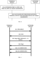
- a 2-step RACH-based SDT procedure between the terminal device and the network device includes the following.
- the terminal device transmits a preamble and a MsgA payload on the initial UL BWP.
- the network device receives the preamble and the MsgA payload on the initial UL BWP.
- the MsgA payload includes an RRC message and UL data.
- the network device transmits a MsgB on the CORESET#0.
- the terminal device receives the MsgB on the CORESET#0.
- the MsgB includes a contention resolution message and does not include an RRC release message.
- the network device transmits an UL scheduling on the initial DL BWP.
- the terminal device receives the UL scheduling on the initial DL BWP.
- the network device transmits the UL scheduling on the first CORESET and/or the first search space. Accordingly, the terminal device receives the UL scheduling on the first CORESET and/or the first search space.
- the network device transmits a DL scheduling on the initial DL BWP.
- the terminal device receives the DL scheduling on the initial DL BWP.
- the network device transmits the DL scheduling on the first CORESET and/or the first search space. Accordingly, the terminal device receives the DL scheduling on the first CORESET and/or the first search space.
- a 2-step RACH-based SDT procedure between the terminal device and the network device includes the following,
- the terminal device transmits a preamble and a MsgA payload on the initial UL BWP.
- the network device only receives the preamble on the initial UL BWP, but failed to receive the MsgA payload.
- the network device transmits an RAR on the CORESET#0.
- the terminal device receives the RAR on the CORESET#0.
- the terminal device transmits a Msg3 on the initial UL BWP.
- the network device receives the Msg3 on the initial UL BWP.
- the Msg3 includes an RRC message and UL data.
- the network device transmits a Msg4 on the CORESET#0.
- the terminal device receives the Msg4 on the CORESET#0.
- the Msg4 includes a contention resolution message and does not include an RRC release message.
- the network device transmits an UL scheduling on the initial DL BWP.
- the terminal device receives the UL scheduling on the initial DL BWP.
- the network device transmits the UL scheduling on the first CORESET and/or the first search space. Accordingly, the terminal device receives the UL scheduling on the first CORESET and/or the first search space.
- the network device transmits a DL scheduling on the initial DL BWP.
- the terminal device receives the DL scheduling on the initial DL BWP.
- the network device transmits the DL scheduling on the first CORESET and/or the first search space. Accordingly, the terminal device receives the DL scheduling on the first CORESET and/or the first search space.
- the terminal device can first implement a random access procedure on the initial UL BWP and the CORESET#0 in the initial DL BWP, and then switch from the CORESET#0 to the initial DL BWP with a larger bandwidth or switch from the CORESET#0 to the first CORESET and/or the first search space with a larger bandwidth, which can facilitate subsequent UL and DL scheduling as well as UL and DL transmission, thereby improving data transmission capability in an SDT procedure.
- the target bandwidth includes the first UL BWP and the first DL BWP.
- FIG. 10 is a flowchart of a method for data transmission provided in an exemplary implementation of the disclosure.
- the method can be applied to the communication system illustrated in FIG. 3 .
- the method includes the following.
- Step 1010 the terminal device determines the first UL BWP and the first DL BWP as the target bandwidth.
- the first UL BWP and the first DL BWP are BWPs configured for the terminal device and dedicated for the RACH-based SDT procedure.
- the first DL BWP has a CORESET#0.
- the first UL BWP and the first DL BWP are determined based on an SIB 1 scheduled by the CORESET#0.
- the terminal device receives the SIB1 scheduled by the CORESET#0, and determines the first UL BWP and the first DL BWP based on the SIB1.
- the terminal device determines the CORESET#0 as follows. After cell search is completed, the terminal device obtains an SSB from a network-device side, determines a frequency-domain location of the SSB, then determines, based on a PBCH in the SSB, a frequency offset value of the CORESET#0 relative to the SSB, and thus determines the CORESET#0 based on the frequency location of the SSB and the frequency offset value of the CORESET#0 relative to the SSB.
- Step 1020 the terminal device performs the RACH-based SDT procedure with the network device on the target bandwidth.
- the RACH-based SDT procedure includes a 4-step RACH-based SDT procedure and a 2-step RACH-based SDT procedure.
- the terminal device transmits to the network device on the first UL BWP at least one of a preamble, a Msg3, a Msg3 retransmission, or an UL transmission dynamically scheduled by the network device. Accordingly, the network device receives, on the first UL BWP, at least one of the preamble, the Msg3, the Msg3 retransmission, or the UL transmission dynamically scheduled by the network device transmitted by the terminal device.
- the terminal device receives, on the first DL BWP, at least one of an RAR, a Msg3 retransmission indication, an UL scheduling, a DL scheduling, or a Msg4 transmitted by the network device. Accordingly, the network device transmits to the terminal device on the first DL BWP at least one of the RAR, the Msg3 retransmission indication, the UL scheduling, the DL scheduling, or the Msg4.
- the UL scheduling and the DL scheduling belong to the same RACH-based SDT procedure.
- a 4-step RACH-based SDT procedure between the terminal device and the network device includes the following.
- the terminal device transmits a preamble on the first UL BWP.
- the network device receives the preamble on the first UL BWP.
- the network device transmits an RAR on the first DL BWP.
- the terminal device receives the RAR on the first DL BWP.
- the terminal device transmits a Msg3 on the first UL BWP.
- the network device receives the Msg3 on the first UL BWP.
- the Msg3 includes an RRC message and UL data.
- the network device transmits a Msg4 on the first DL BWP.
- the terminal device receives the Msg4 on the first DL BWP.
- the network device transmits an UL scheduling on the first DL BWP.
- the terminal device receives the UL scheduling on the first DL BWP.
- the network device transmits a DL scheduling on the first DL BWP.
- the terminal device receives the DL scheduling on the first DL BWP.
- the terminal device performs a 2-step RACH-based SDT procedure with the network device on the target bandwidth.
- the terminal device transmits to the network device on the first UL BWP at least one of a preamble, a MsgA payload, a Msg3, a Msg3 retransmission, or an UL transmission dynamically scheduled by the network device. Accordingly, the network device receives, on the first UL BWP, at least one of the preamble, the MsgA payload, the Msg3, the Msg3 retransmission, or the UL transmission dynamically scheduled by the network device transmitted by the terminal device.
- the terminal device receives, on the first DL BWP, at least one of an RAR, a Msg3 retransmission indication, a Msg4, an UL scheduling, a DL scheduling, or a MsgB transmitted by the network device. Accordingly, the network device transmits to the terminal device on the first DL BWP at least one of the RAR, the Msg3 retransmission indication, the Msg4, the UL scheduling, the DL scheduling, or the MsgB.
- the UL scheduling and the DL scheduling belong to the same RACH-based SDT procedure.
- a 2-step RACH-based SDT procedure between the terminal device and the network device includes the following.
- the terminal device transmits a preamble and a MsgA payload on the first UL BWP.
- the network device receives the preamble and the MsgA payload on the first UL BWP.
- the MsgA payload includes an RRC message and UL data.
- the network device transmits a MsgB on the first DL BWP.
- the terminal device receives the MsgB on the first DL BWP.
- the network device transmits an UL scheduling on the first DL BWP.
- the terminal device receives the UL scheduling on the first DL BWP.
- the network device transmits a DL scheduling on the first DL BWP.
- the terminal device receives the DL scheduling on the first DL BWP.
- a 2-step RACH-based SDT procedure between the terminal device and the network device includes the following.
- the terminal device transmits a preamble and a MsgA payload on the first UL BWP.
- the network device only receives the preamble on the first UL BWP, but failed to receive the MsgA payload.
- the network device transmits an RAR on the first DL BWP.
- the terminal device receives the RAR on the first DL BWP.
- the terminal device transmits a Msg3 on the first UL BWP.
- the network device receives the Msg3 on the first UL BWP.
- the Msg3 includes an RRC message and UL data.
- the network device transmits a Msg4 on the first DL BWP.
- the terminal device receives the Msg4 on the first DL BWP.
- the network device transmits an UL scheduling on the first DL BWP.
- the terminal device receives the UL scheduling on the first DL BWP.
- the network device transmits a DL scheduling on the first DL BWP.
- the terminal device receives the DL scheduling on the first DL BWP.
- the first UL BWP and the first DL BWP are dedicatedly configured for a RACH-based SDT procedure, so that the terminal device and the network device can implement the RACH-based SDT procedure on the first UL BWP and the first DL BWP.
- steps executed by the terminal device may be separately implemented as a method for data transmission at a terminal-device side
- steps executed by the network device may be separately implemented as a method for data transmission at a network-device side.
- FIG. 14 is a structural block diagram of an apparatus for data transmission provided in an exemplary implementation of the disclosure.
- the apparatus may be implemented as a terminal device or a part of the terminal device.
- the apparatus includes a bandwidth determining module 1401 and a transmitting module 1402.
- the bandwidth determining module 1401 is configured to determine a target bandwidth used for a RACH-based SDT procedure.
- the transmitting module 1402 is configured to perform the RACH-based SDT procedure with a network device on the target bandwidth, where the SDT procedure is a data transmission procedure in an inactive state of the terminal device.
- the bandwidth determining module 1401 is configured to determine an initial UL BWP and an initial DL BWP as the target bandwidth, where the initial DL BWP has a CORESET#0.
- the RACH includes a 4-step RACH
- the transmitting module 1402 is configured to transmit to the network device on the initial UL BWP at least one of a preamble, a Msg3, a Msg3 retransmission, or an UL transmission dynamically scheduled by the network device.
- the RACH includes a 4-step RACH
- the transmitting module 1402 is configured to receive, on the CORESET#0 in the initial DL BWP, at least one of an RAR, a Msg3 retransmission indication, or a Msg4 transmitted by the network device.
- the transmitting module 1402 is configured to receive a resource scheduling on the initial DL BWP when the Msg4 includes a contention resolution message and does not include a radio resource control (RRC) release message, where the resource scheduling includes at least one of an UL scheduling or a DL scheduling.
- RRC radio resource control
- the initial DL BWP further has a first CORESET and/or a first search space, where the first CORESET is a CORESET configured for the terminal device in the initial DL BWP, and the first search space is a search space configured for the terminal device in the initial DL BWP.
- the transmitting module 1402 is configured to receive a resource scheduling on the first CORESET and/or the first search space when the Msg4 includes a contention resolution message and does not include an RRC release message, where the resource scheduling includes at least one of an UL scheduling or a DL scheduling.
- the RACH includes a 2-step RACH
- the transmitting module 1402 is configured to transmit to the network device on the initial UL BWP at least one of a preamble, a MsgA payload, a Msg3, a Msg3 retransmission, or an UL transmission dynamically scheduled by the network device.
- the RACH includes a 2-step RACH
- the transmitting module 1402 is configured to receive, on the CORESET#0 in the initial DL BWP, at least one of an RAR, a Msg3 retransmission indication, a Msg4, or a MsgB transmitted by the network device.
- the transmitting module 1402 is configured to receive a resource scheduling on the initial DL BWP when the MsgB includes a contention resolution message and does not include an RRC release message, where the resource scheduling includes at least one of an UL scheduling or a DL scheduling; or receive a resource scheduling on the initial DL BWP when the Msg4 includes a contention resolution message and does not includes an RRC release message, where the resource scheduling includes at least one of an UL scheduling or a DL scheduling.
- the initial DL BWP further has a first CORESET and/or a first search space, where the first CORESET is a CORESET configured for the terminal device in the initial DL BWP, and the first search space is a search space configured for the terminal device in the initial DL BWP.
- the transmitting module 1402 is configured to receive a resource scheduling on the first CORESET and/or the first search space when the MsgB includes a contention resolution message and does not include an RRC release message, where the resource scheduling includes at least one of an UL scheduling or a DL scheduling; or receive a resource scheduling on the first CORESET and/or the first search space when the Msg4 includes a contention resolution message and does not include an RRC release message, where the resource scheduling includes at least one of an UL scheduling or a DL scheduling.
- the UL scheduling and the DL scheduling belong to the same RACH-based SDT procedure.
- the first CORESET and/or the first search space is determined based on an SIB1 scheduled by the CORESET#0.
- the initial UL BWP and the initial DL BWP are determined based on the SIB1 scheduled by the CORESET#0.
- the bandwidth determining module 1401 is configured to determine a first UL BWP and a first DL BWP as the target bandwidth, where the first UL BWP and the first DL BWP are BWPs configured for the terminal device and dedicated for the RACH-based SDT procedure.
- the RACH includes a 4-step RACH
- the transmitting module 1402 is configured to transmit to the network device on the first UL BWP at least one of a preamble, a Msg3, a Msg3 retransmission, or an UL transmission dynamically scheduled by the network device.
- the RACH includes a 4-step RACH
- the transmitting module 1402 is configured to receive, on the first DL BWP, at least one of an RAR, a Msg3 retransmission indication, an UL scheduling, a DL scheduling, or a Msg4 transmitted by the network device.
- the RACH includes a 2-step RACH
- the transmitting module 1402 is configured to transmit to the network device on the first UL BWP at least one of a preamble, a MsgA payload, a Msg3, a Msg3 retransmission, or an UL transmission dynamically scheduled by the network device.
- the RACH includes a 2-step RACH
- the transmitting module 1402 is configured to receive, on the first DL BWP, at least one of an RAR, a Msg3 retransmission indication, a Msg4, an UL scheduling, a DL scheduling, or a MsgB transmitted by the network device.
- the UL scheduling and the DL scheduling belong to the same RACH-based SDT procedure.
- the first UL BWP and the first DL BWP are determined based on an SIB1 scheduled by a CORESET#0.
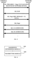
- FIG. 15 is a structural block diagram of an apparatus for data transmission provided in an exemplary implementation of the disclosure.
- the apparatus may be implemented as a network device or a part of the network device.
- the apparatus includes a transmitting module 1501.
- the transmitting module 1501 is configured to perform a RACH-based SDT procedure with a terminal device on a target bandwidth, where the SDT procedure is a data transmission procedure in an inactive state of the terminal device.
- the target bandwidth includes an initial UL BWP and an initial DL BWP, and the initial DL BWP has a CORESET#0.
- the RACH includes a 4-step RACH
- the transmitting module 1501 is configured to receive, on the initial UL BWP, at least one of a preamble, a Msg3, a Msg3 retransmission, or an UL transmission dynamically scheduled by the network device transmitted by the terminal device.
- the RACH includes a 4-step RACH
- the transmitting module 1501 is configured to transmit to the terminal device on the CORESET#0 in the initial DL BWP at least one of an RAR, a Msg3 retransmission indication, or a message 4 (Msg4).
- the transmitting module 1501 is configured to transmit a resource scheduling on the initial DL BWP when the Msg4 includes a contention resolution message and does not include a radio resource control (RRC) release message, where the resource scheduling includes at least one of an UL scheduling or a DL scheduling.
- RRC radio resource control
- the initial DL BWP further has a first CORESET and/or a first search space, where the first CORESET is a CORESET configured for the terminal device in the initial DL BWP, and the first search space is a search space configured for the terminal device in the initial DL BWP.
- the transmitting module 1501 is configured to transmit a resource scheduling on the first CORESET and/or the first search space when the Msg4 includes a contention resolution message and does not include an RRC release message, where the resource scheduling includes at least one of an UL scheduling or a DL scheduling.
- the RACH includes a 2-step RACH
- the transmitting module 1501 is configured to receive, on the initial UL BWP, at least one of a preamble, a MsgA payload, a Msg3, a Msg3 retransmission, or an UL transmission dynamically scheduled by the network device transmitted by the terminal device.
- the RACH includes a 2-step RACH
- the transmitting module 1501 is configured to transmit to the terminal device on the CORESET#0 in the initial DL BWP at least one of an RAR, a Msg3 retransmission indication, a Msg4, or a MsgB.
- the transmitting module 1501 is configured to transmit a resource scheduling on the initial DL BWP when the MsgB includes a contention resolution message and does not include an RRC release message, where the resource scheduling includes at least one of an UL scheduling or a DL scheduling; or transmit a resource scheduling on the initial DL BWP when the Msg4 includes a contention resolution message and does not includes an RRC release message, where the resource scheduling includes at least one of an UL scheduling or a DL scheduling.
- the initial DL BWP further has a first CORESET and/or a first search space, where the first CORESET is a CORESET configured for the terminal device in the initial DL BWP, and the first search space is a search space configured for the terminal device in the initial DL BWP.
- the transmitting module 1501 is configured to transmit a resource scheduling on the first CORESET and/or the first search space when the MsgB includes a contention resolution message and does not include an RRC release message, where the resource scheduling includes at least one of an UL scheduling or a DL scheduling; or transmit a resource scheduling on the first CORESET and/or the first search space when the Msg4 includes a contention resolution message and does not include an RRC release message, where the resource scheduling includes at least one of an UL scheduling or a DL scheduling.
- the UL scheduling and the DL scheduling belong to the same RACH-based SDT procedure.
- the first CORESET and/or the first search space is determined based on an SIB1 scheduled by the CORESET#0.
- the initial UL BWP and the initial DL BWP are determined based on the SIB1 scheduled by the CORESET#0.
- the target bandwidth includes a first UL BWP and a first DL BWP
- the first UL BWP and the first DL BWP are BWPs configured for the terminal device and dedicated for the RACH-based SDT procedure.
- the RACH includes a 4-step RACH
- the transmitting module 1501 is configured to receive, on the first UL BWP, at least one of a preamble, a Msg3, a Msg3 retransmission, or an UL transmission dynamically scheduled by the network device transmitted by the terminal device.
- the RACH includes a 4-step RACH
- the transmitting module 1501 is configured to transmit to the terminal device on the first DL BWP at least one of an RAR, a Msg3 retransmission indication, an UL scheduling, a DL scheduling, or a Msg4.
- the RACH includes a 2-step RACH
- the transmitting module 1501 is configured to receive, on the first UL BWP, at least one of a preamble, a MsgA payload, a Msg3, a Msg3 retransmission, or an UL transmission dynamically scheduled by the network device transmitted by the terminal device.
- the RACH includes a 2-step RACH
- the transmitting module 1501 is configured to transmit to the terminal device on the first DL BWP at least one of an RAR, a Msg3 retransmission indication, a Msg4, an UL scheduling, a DL scheduling, or a MsgB.
- the UL scheduling and the DL scheduling belong to the same RACH-based SDT procedure.
- the first UL BWP and the first DL BWP are determined based on an SIB1 scheduled by a CORESET#0.
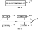
- FIG. 16 is a schematic structural diagram of a communication device (a terminal device or a network device) provided in an exemplary implementation of the disclosure.
- the communication device includes a processor 101, a receiver 102, a transmitter 103, a memory 104, and a bus 105.
- the processor 101 includes one or more processing cores, and the processor 101 executes various function applications and information processing by running software programs and modules.
- the receiver 102 and the transmitter 103 may be implemented as a communication assembly, where the communication assembly may be a communication chip.
- the memory 104 is coupled with the processor 101 through the bus 105.
- the memory 104 may be configured to store at least one instruction.
- the processor 101 is configured to execute the at least one instruction to implement various steps in the foregoing method implementations.
- the memory 104 may be implemented by any type of volatile or nonvolatile storage device or combination thereof.
- the volatile or non-volatile storage device includes, but is not limited to, a magnetic disk or an optical disk, an electrically-erasable programmable read only memory (EEPROM), an erasable programmable ROM (EPROM), a static random access memory (SRAM), a ROM, a magnetic memory, a flash memory, a PROM.
- a processor and a transceiver in the computer device involved in implementations of the disclosure can execute the steps performed by the terminal device in the method illustrated in any one of FIG. 4 to FIG. 13 described above, which will not be repeated herein.
- the computer device is implemented as a terminal device.
- the processor is configured to determine a target bandwidth used for a RACH-based SDT procedure.
- the transceiver is configured to perform the RACH-based SDT procedure with a network device on the target bandwidth, where the SDT procedure is a data transmission procedure in an inactive state of the terminal device.
- a processor and a transceiver in the computer device involved in implementations of the disclosure can execute the steps performed by the network device in the method illustrated in any one of FIG. 4 to FIG. 13 described above, which will not be repeated herein.
- the computer device is implemented as a network device.
- the transceiver is configured to perform a RACH-based SDT procedure with a terminal device on a target bandwidth, where the SDT procedure is a data transmission procedure in an inactive state of the terminal device.
- a computer-readable storage medium is further provided.
- the computer-readable storage medium is configured to store at least one instruction, at least one program, a code set, or an instruction set which is loaded and executed by a processor to implement the method for data transmission that is executed by the communication device and provided in the foregoing method implementations.
- a chip is further provided.
- the chip includes a programmable logic circuit or a program instruction.
- the chip when run on the computer device, is configured to implement the method for data transmission described in the above aspects.
- a computer program product is further provided.
- the computer program product when executed on a processor of the computer device, is operable with the computer device to implement the method for data transmission described in the above aspects.
- the program may be stored in a computer-readable storage medium.
- the storage medium may be a ROM, a magnetic disk, or an optical disk.
Landscapes
- Engineering & Computer Science (AREA)
- Computer Networks & Wireless Communication (AREA)
- Signal Processing (AREA)
- Mobile Radio Communication Systems (AREA)
- Communication Control (AREA)
Claims (11)
- Verfahren für eine Datenübertragung, das in einer Endgerätevorrichtung angewandt wird und das umfasst:Ermitteln eines anfänglichen Uplink-Bandbreitenanteils (Uplink Bandwidth Part, UL-BWP) und eines anfänglichen Downlink-BWP (DL-BWP) als eine Zielbandbreite, die für einen Direktzugriffskanal-basierten (Random Access Channel based, RACH-basierten) Prozess einer kleinen Datenübertragung (Small Data Transmission procedure, SDT-Prozess) verwendet wird, wobei der anfängliche DL-BWP einen Steuerressourcensatz #0, CORESET#0, aufweist, wobei der RACH einen 4-stufigen RACH umfasst; undDurchführen (420) des RACH-basierten SDT-Prozesses mit einer Netzwerkvorrichtung auf der Zielbandbreite, wobei das Durchführen (420) umfasst:
Empfangen, auf dem CORESET#0 in der anfänglichen DL-BWP, mindestens einer von einer Direktzugriffsantwort (Random Access Response, RAR), einer Anzeige einer Msg3-Neuübertragung oder einer Nachricht 4 (Message 4, Msg4), die von der Netzwerkvorrichtung übertragen wird, wobei der SDT-Prozess ein Datenübertragungsprozess in einem inaktiven Zustand der Endgerätevorrichtung ist. - Verfahren nach Anspruch 1, wobei das Durchführen des RACH-basierten SDT-Prozesses mit der Netzwerkvorrichtung auf der Zielbandbreite umfasst:
Übertragen zu der Netzwerkvorrichtung auf der anfänglichen UL-BWP mindestens einer von einer Präambel, einer Nachricht 3 (Msg3), einer Msg3-Neuübertragung oder einer UL-Übertragung, die durch die Netzwerkvorrichtung dynamisch geplant wird. - Verfahren nach Anspruch 1, wobei der anfängliche UL-BWP und die anfängliche DL-BWP basierend auf einem Systeminformationsblock 1, SIB1, ermittelt werden, der durch den CORESET#0 geplant wird.
- Verfahren nach Anspruch 1, das ferner umfasst:
Empfangen einer Ressourcenplanung auf dem anfänglichen DL-BWP, wenn die Msg4 eine Konfliktauflösungsnachricht umfasst, aber keine Freigabenachricht einer Funkressourcensteuerung (Radio Resource Control release message, RRC-Freigabenachricht) umfasst, wobei die Ressourcenplanung mindestens eine von einer UL-Planung und einer DL-Planung umfasst. - Verfahren nach Anspruch 1, wobeider anfängliche DL-BWP ferner eine ersten CORESET und/oder einen ersten Suchraum aufweist, wobei der erste CORESET ein CORESET ist, der für die Endgerätevorrichtung in dem anfänglichen DL-BWP konfiguriert ist, und wobei der erste Suchraum ein Suchraum ist, der für die Endgerätevorrichtung in dem anfänglichen DL-BWP konfiguriert ist; undwobei das Verfahren ferner umfasst:
Empfangen einer Ressourcenplanung auf dem ersten CORESET und/oder dem ersten Suchraum, wenn die Msg4 eine Konfliktauflösungsnachricht umfasst, aber keine RRC-Freigabenachricht umfasst, wobei die Ressourcenplanung mindestens eine von einer UL-Planung und einer DL-Planung umfasst. - Verfahren für eine Datenübertragung, das in einer Netzwerkvorrichtung angewandt wird und das umfasst:Durchführen (420) eines Direktzugriffskanal-basierten (Random Access Channel based, RACH-basierten) Prozesses einer kleinen Datenübertragung (Small Data Transmission procedure, SDT-Prozess) mit einer Endgerätevorrichtung auf einer Zielbandbreite, wobei der SDT-Prozess ein Datenübertragungsprozess in einem inaktiven Zustand der Endgerätevorrichtung ist; wobei die Zielbandbreite einen anfänglichen Uplink-Bandbreitenanteil (Uplink Bandwidth Part, UL-BWP) und einen anfänglichen Downlink-BWP (DL-BWP) umfasst und wobei der anfängliche DL-BWP einen Steuerressourcensatz #0, CORESET#0, aufweist;wobei der RACH einen 4-stufigen RACH umfasst, und wobei das Durchführen des RACH-basierten SDT-Prozesses mit der Endgerätevorrichtung auf der Zielbandbreite umfasst:
Übertragen, zu der Endgerätevorrichtung auf dem CORESET#0 in der anfänglichen DL-BWP, mindestens eine von einer Direktzugriffsantwort (Random Access Response, RAR), einer Anzeige einer Msg3-Neuübertragung oder einer Nachricht 4 (Message 4, Msg4). - Verfahren nach Anspruch 6, das ferner umfasst:
Übertragen einer Ressourcenplanung auf dem anfänglichen DL-BWP, wenn die Msg4 eine Konfliktauflösungsnachricht umfasst, aber keine Freigabenachricht einer Funkressourcensteuerung (Radio Resource Control release message, RRC-Freigabenachricht) umfasst, wobei die Ressourcenplanung mindestens eine von einer UL-Planung und einer DL-Planung umfasst. - Verfahren nach Anspruch 6, das ferner umfasst:
Übertragen einer Ressourcenplanung auf dem ersten CORESET und/oder dem ersten Suchraum, wenn die Msg4 eine Konfliktauflösungsnachricht umfasst, aber keine RRC-Freigabenachricht umfasst, wobei die Ressourcenplanung mindestens eine von einer UL-Planung und einer DL-Planung umfasst, wobei der anfängliche DL-BWP ferner eine ersten CORESET und/oder einen ersten Suchraum aufweist, wobei der erste CORESET ein CORESET ist, der für die Endgerätevorrichtung in dem anfänglichen DL-BWP konfiguriert ist, und wobei der erste Suchraum ein Suchraum ist, der für die Endgerätevorrichtung in dem anfänglichen DL-BWP konfiguriert ist. - Endgerätevorrichtung, umfassend:einen Prozessor (101), der konfiguriert ist zum Ermitteln eines anfänglichen Uplink-Bandbreitenanteils (Uplink Bandwidth Part, UL-BWP) und eines anfänglichen Downlink-BWP (DL-BWP) als eine Zielbandbreite, die für einen Direktzugriffskanal-basierten (Random Access Channel based, RACH-basierten) Prozess einer kleinen Datenübertragung (Small Data Transmission procedure, SDT-Prozess) verwendet wird, wobei der anfängliche DL-BWP einen Steuerressourcensatz #0, CORESET#0, aufweist, wobei der RACH einen 4-stufigen RACH umfasst; undeinen Transceiver (102), der mit dem Prozessor gekoppelt ist und konfiguriert ist zum Durchführen des RACH-basierten SDT-Prozesses mit einer Netzwerkvorrichtung auf der Zielbandbreite, wobei der SDT-Prozess ein Datenübertragungsprozess in einem inaktiven Zustand der Endgerätevorrichtung ist, und wobei der Transceiver (102), der konfiguriert ist zum Durchführen des RACH-basierten SDT-Prozesses mit einer Netzwerkvorrichtung auf der Zielbandbreite, konfiguriert ist zum:
Empfangen, auf dem CORESET#0 in der anfänglichen DL-BWP, mindestens einer von einer Direktzugriffsantwort (Random Access Response, RAR) einer Anzeige einer Msg3-Neuübertragung oder einer Nachricht 4 (Message 4, Msg4), die von der Netzwerkvorrichtung übertragen wird. - Endgerätevorrichtung nach Anspruch 9, wobei der anfängliche UL-BWP und die anfängliche DL-BWP basierend auf einem Systeminformationsblock 1, SIB1, ermittelt werden, der durch den CORESET#0 geplant wird.
- Netzwerkvorrichtung umfassend:einen Prozessor (101); undeinen Transceiver (102), der mit dem Prozessor gekoppelt ist und konfiguriert ist zum Durchführen eines Direktzugriffskanal-basierten (Random Access Channel based, RACH-basierten) Prozesses einer kleinen Datenübertragung (Small Data Transmission procedure, SDT-Prozess) mit einer Endgerätevorrichtung auf einer Zielbandbreite, wobei:der SDT-Prozess ein Datenübertragungsprozess in einem inaktiven Zustand der Endgerätevorrichtung ist;die Zielbandbreite einen anfänglichen Uplink-Bandbreitenanteil (Uplink Bandwidth Part, UL-BWP) und einen anfänglichen Downlink-BWP (DL-BWP) umfasst und wobei der anfängliche DL-BWP einen Steuerressourcensatz #0, CORESET#0, aufweist; undder RACH einen 4-stufigen RACH umfasst, und wobei der Transceiver, der konfiguriert ist zum Durchführen des RACH-basierten SDT-Prozesses mit der Endgerätevorrichtung auf der Zielbandbreite, konfiguriert ist zum:
Übertragen, zu der Endgerätevorrichtung auf dem CORESET#0 in der anfänglichen DL-BWP, mindestens eine von einer Direktzugriffsantwort (Random Access Response, RAR), einer Anzeige einer Msg3-Neuübertragung oder einer Nachricht 4 (Message 4, Msg4).
Applications Claiming Priority (1)
| Application Number | Priority Date | Filing Date | Title |
|---|---|---|---|
| PCT/CN2021/070666 WO2022147716A1 (zh) | 2021-01-07 | 2021-01-07 | 数据传输方法、装置、通信设备和存储介质 |
Publications (3)
| Publication Number | Publication Date |
|---|---|
| EP4236573A1 EP4236573A1 (de) | 2023-08-30 |
| EP4236573A4 EP4236573A4 (de) | 2023-12-06 |
| EP4236573B1 true EP4236573B1 (de) | 2024-10-16 |
Family
ID=82357759
Family Applications (1)
| Application Number | Title | Priority Date | Filing Date |
|---|---|---|---|
| EP21916774.9A Active EP4236573B1 (de) | 2021-01-07 | 2021-01-07 | Datenübertragungsverfahren und geräte |
Country Status (4)
| Country | Link |
|---|---|
| US (1) | US20230292375A1 (de) |
| EP (1) | EP4236573B1 (de) |
| CN (2) | CN119071919A (de) |
| WO (1) | WO2022147716A1 (de) |
Families Citing this family (2)
| Publication number | Priority date | Publication date | Assignee | Title |
|---|---|---|---|---|
| WO2021149965A1 (en) * | 2020-01-22 | 2021-07-29 | Lg Electronics Inc. | Method and apparatus for performing random access procedure with data transmission in wireless communication system |
| WO2023070543A1 (en) * | 2021-10-29 | 2023-05-04 | Nokia Shanghai Bell Co., Ltd. | Scheduling request and random access triggering for sdt |
Family Cites Families (2)
| Publication number | Priority date | Publication date | Assignee | Title |
|---|---|---|---|---|
| US11277862B2 (en) * | 2017-10-26 | 2022-03-15 | Comcast Cable Communications, Llc | Activation and deactivation of configured grant |
| CN114189839B (zh) * | 2018-03-30 | 2026-01-30 | 维沃移动通信有限公司 | 非同步上行传输方法、终端及网络设备 |
-
2021
- 2021-01-07 WO PCT/CN2021/070666 patent/WO2022147716A1/zh not_active Ceased
- 2021-01-07 EP EP21916774.9A patent/EP4236573B1/de active Active
- 2021-01-07 CN CN202411485991.7A patent/CN119071919A/zh active Pending
- 2021-01-07 CN CN202180068390.4A patent/CN116250351A/zh active Pending
-
2023
- 2023-05-17 US US18/319,128 patent/US20230292375A1/en active Pending
Also Published As
| Publication number | Publication date |
|---|---|
| WO2022147716A1 (zh) | 2022-07-14 |
| EP4236573A4 (de) | 2023-12-06 |
| CN116250351A (zh) | 2023-06-09 |
| CN119071919A (zh) | 2024-12-03 |
| US20230292375A1 (en) | 2023-09-14 |
| EP4236573A1 (de) | 2023-08-30 |
| CN116250351A8 (zh) | 2024-05-31 |
Similar Documents
| Publication | Publication Date | Title |
|---|---|---|
| EP3577965B1 (de) | Schnelle umschaltung zwischen steuerkanälen während einer funkressourcensteuerverbindung | |
| TWI491293B (zh) | 處理用於機器型態通訊之資源配置的方法及其通訊裝置 | |
| CN115669038B (zh) | 波束管理方法、装置、设备及存储介质 | |
| US20180110088A1 (en) | Dual active connections over single radio user equipment | |
| EP3043611B1 (de) | Verfahren, vorrichtung und system zur übertragung von informationen | |
| CN111165060A (zh) | 随机接入方法、装置以及通信系统 | |
| CN109891965B (zh) | 上行传输控制方法及其装置、通信系统 | |
| US20250097777A1 (en) | Cell access method and apparatus, and device and readable storage medium | |
| WO2021043416A1 (en) | Idle state small data transmissions for wireless networks | |
| CN113647126A (zh) | 一种非连续接收的方法、电子设备及存储介质 | |
| WO2021223221A1 (zh) | 上行发送方法、装置、设备及存储介质 | |
| US12349164B2 (en) | Method and device for data transmission, and storage medium | |
| US20230292375A1 (en) | Method for data transmission and terminal device | |
| US20180376514A1 (en) | Methods of uplink broadcast, terminal device, and network node | |
| EP4014694A1 (de) | Verbesserte mehrfachverbindungsoperationen | |
| KR20220007638A (ko) | D2d 시스템 중의 통신 방법 및 단말 장치, 네트워크 장치 | |
| KR102460264B1 (ko) | 통신 네트워크에서 d2d 통신을 지원하는 통신 노드의 동작 방법 | |
| EP4240098B1 (de) | Datenübertragungsverfahren und -vorrichtungen | |
| CN115777224B (zh) | 数据传输方法、装置、设备及存储介质 | |
| EP4366455A1 (de) | Kommunikationsverfahren, ressourcenkonfigurationsverfahren, vorrichtung, netzwerkknoten, system und medium | |
| US12477522B2 (en) | Random access resource determination method and apparatus, communication device, and storage medium | |
| CN117280838A (zh) | 用户设备、无线电网络节点以及在无线通信网络中执行的方法 | |
| CN116569636B (zh) | 小数据传输方法、装置、设备及介质 | |
| US12526845B2 (en) | Method and apparatus for requesting other system information, and device medium | |
| CN116830779A (zh) | 资源处理方法、装置、设备及存储介质 |
Legal Events
| Date | Code | Title | Description |
|---|---|---|---|
| STAA | Information on the status of an ep patent application or granted ep patent |
Free format text: STATUS: THE INTERNATIONAL PUBLICATION HAS BEEN MADE |
|
| PUAI | Public reference made under article 153(3) epc to a published international application that has entered the european phase |
Free format text: ORIGINAL CODE: 0009012 |
|
| STAA | Information on the status of an ep patent application or granted ep patent |
Free format text: STATUS: REQUEST FOR EXAMINATION WAS MADE |
|
| 17P | Request for examination filed |
Effective date: 20230523 |
|
| AK | Designated contracting states |
Kind code of ref document: A1 Designated state(s): AL AT BE BG CH CY CZ DE DK EE ES FI FR GB GR HR HU IE IS IT LI LT LU LV MC MK MT NL NO PL PT RO RS SE SI SK SM TR |
|
| REG | Reference to a national code |
Ref country code: DE Ref legal event code: R079 Free format text: PREVIOUS MAIN CLASS: H04W0074000000 Ipc: H04W0074080000 Ref country code: DE Ref legal event code: R079 Ref document number: 602021020501 Country of ref document: DE Free format text: PREVIOUS MAIN CLASS: H04W0074000000 Ipc: H04W0074080000 |
|
| A4 | Supplementary search report drawn up and despatched |
Effective date: 20231108 |
|
| RIC1 | Information provided on ipc code assigned before grant |
Ipc: H04W 72/1268 20230101ALN20231102BHEP Ipc: H04W 74/08 20090101AFI20231102BHEP |
|
| DAV | Request for validation of the european patent (deleted) | ||
| DAX | Request for extension of the european patent (deleted) | ||
| REG | Reference to a national code |
Ref country code: DE Free format text: PREVIOUS MAIN CLASS: H04W0074080000 Ref country code: DE Ref legal event code: R079 Ref document number: 602021020501 Country of ref document: DE Free format text: PREVIOUS MAIN CLASS: H04W0074080000 Ipc: H04W0074083300 |
|
| GRAP | Despatch of communication of intention to grant a patent |
Free format text: ORIGINAL CODE: EPIDOSNIGR1 |
|
| STAA | Information on the status of an ep patent application or granted ep patent |
Free format text: STATUS: GRANT OF PATENT IS INTENDED |
|
| RIC1 | Information provided on ipc code assigned before grant |
Ipc: H04W 72/1268 20230101ALN20240417BHEP Ipc: H04W 74/0833 20240101AFI20240417BHEP |
|
| INTG | Intention to grant announced |
Effective date: 20240508 |
|
| GRAS | Grant fee paid |
Free format text: ORIGINAL CODE: EPIDOSNIGR3 |
|
| GRAA | (expected) grant |
Free format text: ORIGINAL CODE: 0009210 |
|
| STAA | Information on the status of an ep patent application or granted ep patent |
Free format text: STATUS: THE PATENT HAS BEEN GRANTED |
|
| AK | Designated contracting states |
Kind code of ref document: B1 Designated state(s): AL AT BE BG CH CY CZ DE DK EE ES FI FR GB GR HR HU IE IS IT LI LT LU LV MC MK MT NL NO PL PT RO RS SE SI SK SM TR |
|
| REG | Reference to a national code |
Ref country code: GB Ref legal event code: FG4D |
|
| REG | Reference to a national code |
Ref country code: CH Ref legal event code: EP Ref country code: DE Ref legal event code: R096 Ref document number: 602021020501 Country of ref document: DE |
|
| REG | Reference to a national code |
Ref country code: IE Ref legal event code: FG4D |
|
| REG | Reference to a national code |
Ref country code: LT Ref legal event code: MG9D |
|
| REG | Reference to a national code |
Ref country code: AT Ref legal event code: MK05 Ref document number: 1733953 Country of ref document: AT Kind code of ref document: T Effective date: 20241016 |
|
| PG25 | Lapsed in a contracting state [announced via postgrant information from national office to epo] |
Ref country code: NL Free format text: LAPSE BECAUSE OF FAILURE TO SUBMIT A TRANSLATION OF THE DESCRIPTION OR TO PAY THE FEE WITHIN THE PRESCRIBED TIME-LIMIT Effective date: 20241016 |
|
| PG25 | Lapsed in a contracting state [announced via postgrant information from national office to epo] |
Ref country code: NL Free format text: LAPSE BECAUSE OF FAILURE TO SUBMIT A TRANSLATION OF THE DESCRIPTION OR TO PAY THE FEE WITHIN THE PRESCRIBED TIME-LIMIT Effective date: 20241016 |
|
| P01 | Opt-out of the competence of the unified patent court (upc) registered |
Free format text: CASE NUMBER: APP_9894/2025 Effective date: 20250226 |
|
| PG25 | Lapsed in a contracting state [announced via postgrant information from national office to epo] |
Ref country code: IS Free format text: LAPSE BECAUSE OF FAILURE TO SUBMIT A TRANSLATION OF THE DESCRIPTION OR TO PAY THE FEE WITHIN THE PRESCRIBED TIME-LIMIT Effective date: 20250216 Ref country code: HR Free format text: LAPSE BECAUSE OF FAILURE TO SUBMIT A TRANSLATION OF THE DESCRIPTION OR TO PAY THE FEE WITHIN THE PRESCRIBED TIME-LIMIT Effective date: 20241016 Ref country code: PT Free format text: LAPSE BECAUSE OF FAILURE TO SUBMIT A TRANSLATION OF THE DESCRIPTION OR TO PAY THE FEE WITHIN THE PRESCRIBED TIME-LIMIT Effective date: 20250217 |
|
| PGFP | Annual fee paid to national office [announced via postgrant information from national office to epo] |
Ref country code: DE Payment date: 20250121 Year of fee payment: 5 |
|
| PG25 | Lapsed in a contracting state [announced via postgrant information from national office to epo] |
Ref country code: FI Free format text: LAPSE BECAUSE OF FAILURE TO SUBMIT A TRANSLATION OF THE DESCRIPTION OR TO PAY THE FEE WITHIN THE PRESCRIBED TIME-LIMIT Effective date: 20241016 |
|
| PG25 | Lapsed in a contracting state [announced via postgrant information from national office to epo] |
Ref country code: BG Free format text: LAPSE BECAUSE OF FAILURE TO SUBMIT A TRANSLATION OF THE DESCRIPTION OR TO PAY THE FEE WITHIN THE PRESCRIBED TIME-LIMIT Effective date: 20241016 |
|
| PG25 | Lapsed in a contracting state [announced via postgrant information from national office to epo] |
Ref country code: ES Free format text: LAPSE BECAUSE OF FAILURE TO SUBMIT A TRANSLATION OF THE DESCRIPTION OR TO PAY THE FEE WITHIN THE PRESCRIBED TIME-LIMIT Effective date: 20241016 |
|
| PG25 | Lapsed in a contracting state [announced via postgrant information from national office to epo] |
Ref country code: NO Free format text: LAPSE BECAUSE OF FAILURE TO SUBMIT A TRANSLATION OF THE DESCRIPTION OR TO PAY THE FEE WITHIN THE PRESCRIBED TIME-LIMIT Effective date: 20250116 |
|
| PG25 | Lapsed in a contracting state [announced via postgrant information from national office to epo] |
Ref country code: LV Free format text: LAPSE BECAUSE OF FAILURE TO SUBMIT A TRANSLATION OF THE DESCRIPTION OR TO PAY THE FEE WITHIN THE PRESCRIBED TIME-LIMIT Effective date: 20241016 Ref country code: AT Free format text: LAPSE BECAUSE OF FAILURE TO SUBMIT A TRANSLATION OF THE DESCRIPTION OR TO PAY THE FEE WITHIN THE PRESCRIBED TIME-LIMIT Effective date: 20241016 Ref country code: GR Free format text: LAPSE BECAUSE OF FAILURE TO SUBMIT A TRANSLATION OF THE DESCRIPTION OR TO PAY THE FEE WITHIN THE PRESCRIBED TIME-LIMIT Effective date: 20250117 |
|
| PG25 | Lapsed in a contracting state [announced via postgrant information from national office to epo] |
Ref country code: PL Free format text: LAPSE BECAUSE OF FAILURE TO SUBMIT A TRANSLATION OF THE DESCRIPTION OR TO PAY THE FEE WITHIN THE PRESCRIBED TIME-LIMIT Effective date: 20241016 |
|
| PGFP | Annual fee paid to national office [announced via postgrant information from national office to epo] |
Ref country code: FR Payment date: 20250122 Year of fee payment: 5 |
|
| PGFP | Annual fee paid to national office [announced via postgrant information from national office to epo] |
Ref country code: GB Payment date: 20250122 Year of fee payment: 5 |
|
| PG25 | Lapsed in a contracting state [announced via postgrant information from national office to epo] |
Ref country code: RS Free format text: LAPSE BECAUSE OF FAILURE TO SUBMIT A TRANSLATION OF THE DESCRIPTION OR TO PAY THE FEE WITHIN THE PRESCRIBED TIME-LIMIT Effective date: 20250116 |
|
| PG25 | Lapsed in a contracting state [announced via postgrant information from national office to epo] |
Ref country code: SM Free format text: LAPSE BECAUSE OF FAILURE TO SUBMIT A TRANSLATION OF THE DESCRIPTION OR TO PAY THE FEE WITHIN THE PRESCRIBED TIME-LIMIT Effective date: 20241016 |
|
| PG25 | Lapsed in a contracting state [announced via postgrant information from national office to epo] |
Ref country code: DK Free format text: LAPSE BECAUSE OF FAILURE TO SUBMIT A TRANSLATION OF THE DESCRIPTION OR TO PAY THE FEE WITHIN THE PRESCRIBED TIME-LIMIT Effective date: 20241016 |
|
| REG | Reference to a national code |
Ref country code: DE Ref legal event code: R097 Ref document number: 602021020501 Country of ref document: DE |
|
| PG25 | Lapsed in a contracting state [announced via postgrant information from national office to epo] |
Ref country code: EE Free format text: LAPSE BECAUSE OF FAILURE TO SUBMIT A TRANSLATION OF THE DESCRIPTION OR TO PAY THE FEE WITHIN THE PRESCRIBED TIME-LIMIT Effective date: 20241016 |
|
| PG25 | Lapsed in a contracting state [announced via postgrant information from national office to epo] |
Ref country code: RO Free format text: LAPSE BECAUSE OF FAILURE TO SUBMIT A TRANSLATION OF THE DESCRIPTION OR TO PAY THE FEE WITHIN THE PRESCRIBED TIME-LIMIT Effective date: 20241016 |
|
| PG25 | Lapsed in a contracting state [announced via postgrant information from national office to epo] |
Ref country code: SK Free format text: LAPSE BECAUSE OF FAILURE TO SUBMIT A TRANSLATION OF THE DESCRIPTION OR TO PAY THE FEE WITHIN THE PRESCRIBED TIME-LIMIT Effective date: 20241016 |
|
| PG25 | Lapsed in a contracting state [announced via postgrant information from national office to epo] |
Ref country code: CZ Free format text: LAPSE BECAUSE OF FAILURE TO SUBMIT A TRANSLATION OF THE DESCRIPTION OR TO PAY THE FEE WITHIN THE PRESCRIBED TIME-LIMIT Effective date: 20241016 |
|
| PG25 | Lapsed in a contracting state [announced via postgrant information from national office to epo] |
Ref country code: IT Free format text: LAPSE BECAUSE OF FAILURE TO SUBMIT A TRANSLATION OF THE DESCRIPTION OR TO PAY THE FEE WITHIN THE PRESCRIBED TIME-LIMIT Effective date: 20241016 |
|
| PLBE | No opposition filed within time limit |
Free format text: ORIGINAL CODE: 0009261 |
|
| STAA | Information on the status of an ep patent application or granted ep patent |
Free format text: STATUS: NO OPPOSITION FILED WITHIN TIME LIMIT |
|
| REG | Reference to a national code |
Ref country code: CH Ref legal event code: PL |
|
| PG25 | Lapsed in a contracting state [announced via postgrant information from national office to epo] |
Ref country code: SE Free format text: LAPSE BECAUSE OF FAILURE TO SUBMIT A TRANSLATION OF THE DESCRIPTION OR TO PAY THE FEE WITHIN THE PRESCRIBED TIME-LIMIT Effective date: 20241016 |
|
| PG25 | Lapsed in a contracting state [announced via postgrant information from national office to epo] |
Ref country code: LU Free format text: LAPSE BECAUSE OF NON-PAYMENT OF DUE FEES Effective date: 20250107 Ref country code: MC Free format text: LAPSE BECAUSE OF FAILURE TO SUBMIT A TRANSLATION OF THE DESCRIPTION OR TO PAY THE FEE WITHIN THE PRESCRIBED TIME-LIMIT Effective date: 20241016 |
|
| 26N | No opposition filed |
Effective date: 20250717 |
|
| PG25 | Lapsed in a contracting state [announced via postgrant information from national office to epo] |
Ref country code: BE Free format text: LAPSE BECAUSE OF NON-PAYMENT OF DUE FEES Effective date: 20250131 |
|
| PG25 | Lapsed in a contracting state [announced via postgrant information from national office to epo] |
Ref country code: CH Free format text: LAPSE BECAUSE OF NON-PAYMENT OF DUE FEES Effective date: 20250131 |
|
| REG | Reference to a national code |
Ref country code: BE Ref legal event code: MM Effective date: 20250131 |
|
| PG25 | Lapsed in a contracting state [announced via postgrant information from national office to epo] |
Ref country code: IE Free format text: LAPSE BECAUSE OF NON-PAYMENT OF DUE FEES Effective date: 20250107 |