EP4236552B1 - Aktivierungsverfahren für bandbreitenteil und zugehörige produkte - Google Patents
Aktivierungsverfahren für bandbreitenteil und zugehörige produkte Download PDFInfo
- Publication number
- EP4236552B1 EP4236552B1 EP23178869.6A EP23178869A EP4236552B1 EP 4236552 B1 EP4236552 B1 EP 4236552B1 EP 23178869 A EP23178869 A EP 23178869A EP 4236552 B1 EP4236552 B1 EP 4236552B1
- Authority
- EP
- European Patent Office
- Prior art keywords
- bwp
- information
- feedback response
- terminal
- response information
- Prior art date
- Legal status (The legal status is an assumption and is not a legal conclusion. Google has not performed a legal analysis and makes no representation as to the accuracy of the status listed.)
- Active
Links
Images

Classifications
-
- H—ELECTRICITY
- H04—ELECTRIC COMMUNICATION TECHNIQUE
- H04L—TRANSMISSION OF DIGITAL INFORMATION, e.g. TELEGRAPHIC COMMUNICATION
- H04L5/00—Arrangements affording multiple use of the transmission path
- H04L5/0091—Signalling for the administration of the divided path, e.g. signalling of configuration information
- H04L5/0096—Indication of changes in allocation
- H04L5/0098—Signalling of the activation or deactivation of component carriers, subcarriers or frequency bands
-
- H—ELECTRICITY
- H04—ELECTRIC COMMUNICATION TECHNIQUE
- H04L—TRANSMISSION OF DIGITAL INFORMATION, e.g. TELEGRAPHIC COMMUNICATION
- H04L41/00—Arrangements for maintenance, administration or management of data switching networks, e.g. of packet switching networks
- H04L41/08—Configuration management of networks or network elements
- H04L41/0896—Bandwidth or capacity management, i.e. automatically increasing or decreasing capacities
-
- H—ELECTRICITY
- H04—ELECTRIC COMMUNICATION TECHNIQUE
- H04W—WIRELESS COMMUNICATION NETWORKS
- H04W72/00—Local resource management
- H04W72/20—Control channels or signalling for resource management
- H04W72/23—Control channels or signalling for resource management in the downlink direction of a wireless link, i.e. towards a terminal
-
- H—ELECTRICITY
- H04—ELECTRIC COMMUNICATION TECHNIQUE
- H04W—WIRELESS COMMUNICATION NETWORKS
- H04W72/00—Local resource management
- H04W72/04—Wireless resource allocation
- H04W72/044—Wireless resource allocation based on the type of the allocated resource
- H04W72/0453—Resources in frequency domain, e.g. a carrier in FDMA
-
- H—ELECTRICITY
- H04—ELECTRIC COMMUNICATION TECHNIQUE
- H04W—WIRELESS COMMUNICATION NETWORKS
- H04W76/00—Connection management
- H04W76/20—Manipulation of established connections
- H04W76/27—Transitions between radio resource control [RRC] states
Definitions
- the present invention is a divisional application of European Patent Application No. 20201307.4 , which is a divisional application of European Patent Application No. 17922065.2, which has a filing date of September 14, 2017 .
- the present application relates to the field of communication technologies, and in particular, to an activation method for a bandwidth part (BWP) and related products.
- BWP bandwidth part
- the 5th-Generation of mobile communication technology (5G) New Radio (NR) is a newly proposed topic in the 3rd Generation Partnership Project (3GPP) organization.
- 3GPP 3rd Generation Partnership Project
- 4G 4th generation mobile communication
- LTE Long Term Evolution
- the system bandwidth supported by the 5G NR system is much larger than maximum system bandwidth of 20MHz of LTE.
- BWP Bandwidth Part
- a network device may configure one or more BWPs for the terminal, where the BWP mainly includes three parameters: a numerology, which is used to indicate subcarrier spacing (SCS); a center frequency point; and a bandwidth, which is less than or equal to the maximum system bandwidth.
- the BWP is a concept of a frequency domain dimension.
- R1-1716440 discusses issues in CA and BWP for NR including unified framework for CA and BWP handling, timeline with activation/deactivation, and CA with mixed numerology.
- R1-1715571 discusses the activation and deactivation of DL and UL BWPs, the fall back mechanism for activation and the retuning mechanism for BWP switching.
- the present invention is set out in the appended set of claims.
- the embodiment of the present application provides an activation method for bandwidth part (BWP) and related products, so as to achieve that terminal and the network device have consistent understanding of BWP that is actually used, and ensure the accuracy and stability of data scheduling of the communication system.
- BWP bandwidth part
- the embodiment of the present application provides an activation method for bandwidth part (BWP), including:
- the embodiment of the present application provides a terminal, comprising a processing unit and a communication unit, wherein: he processing unit is configured to receive, through the communication unit, first information on a first bandwidth part, BWP, from a network device and ransmit feedback response information corresponding to the first information within a time unit after a time unit occupied by the first information, wherein the first information is used to activate a second BWP; and
- the embodiment of the present application provides a network device, comprising: a processing unit and a communication unit, wherein:the processing unit is configured to transmit, through the communication unit, first information on a first bandwidth part, BWP, and receive feedback response information corresponding to the first information within a time unit after a time unit occupied by the first information, wherein the first information is used to activate a second BWP; and
- a terminal receives first information from a network device on a first BWP in a first time unit, where the first information is used to activate a second BWP; then, the terminal transmits feedback response information corresponding to the first information in the second time unit; and finally, the terminal determines the BWP that is activated after the second time unit.
- the network device can know whether the terminal correctly receives the first information indicating that the second BWP is activated, so as to determine the BWP that is actually activated after the second time unit, so that the terminal and the network side device both can accurately know the actual activated BWP, avoid transmission interruption during BWP activation, and ensure the transmission reliability.
- the network device can switch between different BWPs configured by the terminal by transmitting an instruction, that is, deactivate the current BWP and activate a new BWP.
- the activation instruction may be in the following manners: RRC dedicated signaling; DCI or media access control (MAC) control element (CE); time pattern: that is, switch between different BWPs according to a certain time schedule.
- the embodiment of the present application proposes an activation method for a bandwidth part (BWP) and related products.
- the method includes: the terminal receives first information from a network device on a first BWP in a first time unit, where the first information is used to activate a second BWP; then, the terminal transmits feedback response information corresponding to the first information in the second time unit; and finally, the terminal determines the BWP that is activated after the second time unit.
- the network device can know whether the terminal correctly receives the first information that indicating to activate the second BWP, so as to determine the BWP that is actually activated after the second time unit, so that the terminal and the network side device both can accurately know the actual activated BWP, avoid transmission interruption during BWP activation, and ensure the transmission reliability.
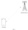
- FIG. 1 is possible network architecture of an example communication system according to an embodiment of the present application.
- the example communication system can be, for example, a 5G NR system and other such communication systems.
- the example communication system specifically includes a network device and a terminal. When the terminal accesses the mobile communication network provided by the network device, the terminal and the network device can communicate with each other and be connected through a wireless link, and the communication connection mode can be a single connection mode or a dual connection mode.
- the network device may be a LTE base station or a NR base station (also referred to as a gNB base station), and when the communication mode is a dual connection mode (may be specifically implemented by the carrier aggregation (CA) technology, or by a plurality of network devices), and the terminal is connected to multiple network devices, the plurality of network devices may be the primary base station MCG and the secondary base station SCG, and data backhaul among the base stations is performed through the backhaul link.
- CA carrier aggregation
- the primary base station may be a LTE base station
- the secondary base station may be a LTE base station
- the primary base station may be an NR base station
- the secondary base station may be a LTE base station
- the primary base station may be an NR base station
- the secondary base station may be an NR base station.
- terminal involved in the embodiment of the present application may include various handheld devices, vehicle-mounted devices, wearable devices, computing devices, all of which have the wireless communication function, or other processing devices connected to the wireless modem, and various forms of user equipment (UE), mobile stations (MS), terminal devices and such. Devices described above are collectively referred to as terminals for ease of description.
- UE user equipment
- MS mobile stations
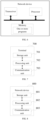
- FIG. 2 is an activation method for a bandwidth part (BWP) according to an embodiment of the present application, which is applied to the above example communication system, and the method includes: In section 201, the terminal receives first information from a network device on a first BWP in a first time unit, the first information is used to activate a second BWP.
- BWP bandwidth part
- time unit may be a time domain unit such as a subframe, a time slot, and a symbol.
- the terminal transmits the feedback response information corresponding to the first information in a second time unit.
- feedback response information includes acknowledgement (ACK)/non-acknowledgment (NACK) information.
- the terminal determines a BWP that is activated after the second time unit.
- the terminal receives a first information from a network device on a first BWP in a first time unit, and the first information is used to activate a second BWP; then, the terminal transmits feedback response information corresponding to the first information in a second time unit; and finally, the terminal determines a BWP that is activated after the second time unit.
- the network device can know whether the terminal correctly receives the first information that indicating to activate the second BWP, so as to determine the BWP that is actually activated after the second time unit, so that the terminal and the network side device both can accurately know the actual activated BWP, avoid transmission interruption during BWP activation, and ensure the transmission reliability.
- the terminal transmits feedback response information corresponding to the first information in the second time unit, including: the terminal transmits the feedback response information on the first BWP in the second time unit.
- the terminal can directly transmit the feedback response information on the first BWP, and does not need to wait for the handover to a new BWP to perform transmission, and the feedback delay is shorter.
- the terminal transmits feedback response information corresponding to the first information in the second time unit, including: the terminal transmits the feedback response information on the second BWP in the second time unit.
- the terminal can transmit feedback response information on the second BWP after the second BWP is activated, and the terminal completes the BWP handover before transmitting the feedback response information, and can directly perform data transmission on a new BWP after transmitting the feedback response information, so as to perform data transmission quickly.
- the terminal transmits feedback response information corresponding to the first information in the second time unit, including: the terminal transmits the feedback response information on a third BWP in the second time unit, a downlink operation of the terminal in the first time unit is on the first BWP, and an uplink operation of the terminal in the first time unit is on the third BWP.
- the downlink operation of the current terminal is on the first BWP
- the uplink operation is on the third BWP
- the terminal can directly transmit the feedback response information on the third BWP, does not need to wait for the handover to a new BWP to perform transmission, and the feedback delay is shorter.
- the terminal transmits feedback response information corresponding to the first information in the second time unit, including: the terminal transmits the feedback response information on the fourth BWP in the second time unit, the second BWP is a full downlink resource, and the fourth BWP is an uplink resource paired with the second BWP.
- the downlink operation of the terminal is on the second BWP in the second time unit
- the uplink operation is on the fourth BWP
- the terminal can directly transmit the feedback response information on the fourth BWP after activating the second BWP, and can directly perform data transmission on a new BWP after transmitting the feedback response information, so as to perform data transmission quickly.
- the terminal transmits feedback response information corresponding to the first information in the second time unit, including: the terminal transmits the feedback response information on a fifth BWP in the second time unit, and the fifth BWP is used to transmit feedback response information transmitted by the terminal.
- the fifth BWP resources are specifically used for transmitting feedback response information, and improving the reliability of the feedback response information transmission.
- the method further includes: the terminal receives the first configuration information from the network device; the terminal determines a BWP that transmits the feedback response information according to the first configuration information.
- the first configuration information can be used to indicate the BWP that transmits the feedback response information, so that the terminal and the network device have consistent understanding of BWP that transmits the feedback response information, and ensure the reliability of the feedback response information transmission.
- the terminal determines the BWP that is activated after the second time unit, including: the terminal correctly receives the first information, and determines to perform data reception and/or transmission on the second BWP after a target time period starting from the second time unit.
- the terminal determines that the first information is correctly received, and transmits feedback response information corresponding to the first information to a network device in the second time unit, it determines that the second BWP is activated after a target time period starting from the second time unit, and data transmission is performed on the second BWP, that is, a solution for accurately determining a time to activate the second BWP based on the result of correctly receiving the first information is proposed, so that the data transmission reliability and response efficiency can be improved.
- the duration of the target time period is configured by the network device; or the duration of the target time period is reported by the terminal; or the duration of the target time period is stipulated by the first preset protocol.
- the feedback response information is transmitted on the second BWP or on the fourth BWP, and the duration of the target time period is zero.
- the terminal determines the BWP that is activated after the second time unit, including: the terminal incorrectly receives the first information, and determines to perform data reception and/or transmission on a previously operating BWP after the second time unit, where the previously operating BWP is a BWP operating in the first time unit.
- the previously operating BWP may be the first BWP and/or the third BWP.
- the terminal determines that the first information is not correctly received, the terminal does not know the activation information transmitted by the network device, and thus continues to operate on the original operating BWP to ensure the reliability and success rate of the feedback response information transmission.
- the method before the terminal determines to transmit the feedback response information corresponding to the first information in the second time unit, the method further includes: the terminal receives the second configuration information from the network device; and the terminal determines the second time unit according to the second configuration information; or the terminal determines the second time unit according to a second preset protocol.
- the second configuration information can accurately indicate the second time unit for transmitting the feedback response information corresponding to the first information, so that the terminal and the network device have consistent understanding of BWP that transmits the feedback response information, and ensure the reliability of the feedback response information transmission.
- the feedback response information is transmitted through an independent uplink control channel.
- the feedback response information corresponding to other downlink data in the second time unit needs to be transmitted, the feedback response information corresponding to the first information is not multiplexed with the feedback response information corresponding to other data onto the same physical channel.
- the first information is transmitted through a downlink control channel; and/or the first information is transmitted through a downlink shared channel.
- FIG. 3 is an activation method for a bandwidth part (BWP) according to an embodiment of the present application.
- the method is applied to the above example communication system, and the method includes: In section 301, the network device transmits first information on a first BWP in a first time unit, and the first information is used to instruct a terminal to activate a second BWP.
- the network device receives feedback response information corresponding to the first information in a second time unit.
- the network device determines, according to the feedback response information, a BWP that is activated after the second time unit.
- the network device first transmits the first information on the first BWP in the first time unit, and the first information is used to instruct the terminal to activate a second BWP; then, the network device receives the feedback response information corresponding to the first information in the second time unit; and finally, the network device determines the BWP that is activated after the second time unit according to the feedback response information.
- the network device can know whether the terminal correctly receives the first information instructing to activate a second BWP, so as to determine the BWP that is actually activated after the second time unit, so that the terminal and the network side device both can accurately know the actual activated BWP, avoid transmission interruption during BWP activation, and ensure the transmission reliability.
- the feedback response information is transmitted on the first BWP; or the feedback response information is transmitted on the second BWP; or the feedback response information is transmitted on a third BWP, where a downlink operation of the terminal in the first time unit is on the first BWP, and an uplink operation of the terminal in the first time unit is on the third BWP; or, the feedback response information is transmitted on a fourth BWP, the second BWP is a full downlink resource, the fourth BWP is an uplink resource paired with the second BWP, or the feedback response information is transmitted on a fifth BWP, and the fifth BWP is configured to transmit the feedback response information transmitted by the terminal.
- the network device determines the BWP that is activated after the second time unit according to the feedback response information, including: the network device determines that the received feedback response information is acknowledgement feedback response information, and determines to perform data reception and/or transmission on the second BWP after a target time period starting from the second time unit.
- the duration of the target time period is configured by the network device; or the duration of the target time period is reported by the terminal; or the duration of the target time period is stipulated by the first preset protocol.
- the acknowledgement feedback response information is transmitted on the second BWP or on the fourth BWP, and the value of the duration of the target time period is zero.
- the terminal determines the BWP that is activated after the second time unit according to the feedback response information, including: the network device determines that the received feedback response information is non-acknowledgment feedback response information or the feedback response information is not received, and determines to perform data reception and/or transmission on the first BWP after the second time unit.
- the method before the network device receives the feedback response information in the second time unit, the method further includes: the network device transmits second configuration information, the second configuration information is used by the terminal to determine the second time unit; or, the network device determines the second time unit according to a second preset protocol.
- the feedback response information is transmitted through an independent uplink control channel.
- the first information is transmitted through a downlink control channel; and/or the first information is transmitted through a downlink shared channel.
- FIG. 4 is an activation method for a bandwidth part (BWP) according to an embodiment of the present application.
- the method is applied to the above example communication system, and the method includes: In section 401, the network device transmits first information on a first BWP in a first time unit, and the first information is used to instruct a terminal to activate a second BWP.
- the terminal receives first information from a network device on a first BWP in a first time unit, and the first information is used to activate a second BWP.
- the terminal transmits feedback response information corresponding to the first information in a second time unit.
- the network device receives feedback response information corresponding to the first information in the second time unit.
- the terminal determines a BWP that is activated after the second time unit.
- the network device determines, according to the feedback response information, a BWP that is activated after the second time unit.
- the terminal receives first information from the network device on the first BWP in the first time unit, and the first information is used to activate the second BWP; then, the terminal transmits feedback response information corresponding to the first information in the second time unit; and finally, the terminal determines the BWP that is activated after the second time unit.
- the network device can know whether the terminal correctly receives the first information indicating that the second BWP is activated, so as to determine the BWP that is actually activated after the second time unit, so that the terminal and the network side device both can accurately know the actual activated BWP, avoid transmission interruption during BWP activation, and ensure the transmission reliability.
- FIG. 5 is a schematic structural diagram of a terminal according to an embodiment of the present invention.
- the terminal includes a processor, a memory, a communication interface, and one or more programs, wherein the one or more programs are stored in the memory, and configured to be executed by the processor, and the one or more programs includes instructions for performing the following steps;
- the terminal receives the first information from the network device on the first BWP in the first time unit, where the first information is used to activate the second BWP; then, the terminal transmits feedback response information corresponding to the first information in the second time unit; and finally, the terminal determines the BWP that is activated after the second time unit.
- the network device can know whether the terminal correctly receives the first information indicating that the second BWP is activated, so as to determine the BWP that is actually activated after the second time unit, so that the terminal and the network side device both can accurately know the actual activated BWP, avoid transmission interruption during BWP activation, and ensure the transmission reliability.
- the instruction in the program is specifically configured to perform following operations: transmit the feedback response information on the first BWP in the second time unit; or transmit the feedback response information on the second BWP in the second time unit; or transmit the feedback response information on the third BWP in the second time unit, where a downlink operation of the terminal in the first time unit is on the first BWP, and an uplink operation of the terminal in the first time unit is on the third BWP; or the terminal transmits the feedback response information on the fourth BWP in the second time unit, the second BWP is a full downlink resource, and the fourth BWP is an uplink resource paired with the second BWP; or the terminal transmits the feedback response information on the fifth BWP in the second time unit, the fifth BWP is used to transmit the feedback response information transmitted by the terminal.
- the program further includes instructions for performing following operations: receive first configuration information from the network device before determining to transmit feedback response information corresponding to the first information in a second time unit; and determine a BWP for transmitting the feedback response information according to the first configuration information.
- the instruction in the program is specifically configured to perform following operations: correctly receive the first information, determine to perform data reception and/or transmission on the second BWP after the target time period starting from the second time unit.
- the duration of the target time period is configured by the network device; or,
- the feedback response information is transmitted on the second BWP or the fourth BWP, and the duration of the target time period is zero.
- the instruction in the program is specifically configured to perform following operations: incorrectly receive the first information, and determines to perform data reception and/or transmission on a previously operating BWP after the second time unit, and the previously operating BWP is a BWP operating in the first time unit.
- the program further includes instructions to perform following operations: receive a second configuration information from the network device before determining to transmit feedback response information corresponding to the first information in a second time unit; and determine the second time unit according to the second configuration information; or determine the second time unit according to a second preset protocol.
- the feedback response information is transmitted through an independent uplink control channel.
- the first information is transmitted through a downlink control channel; and/or the first information is transmitted through a downlink shared channel.
- FIG. 6 is a schematic structural diagram of a network device according to an embodiment of the present invention.
- the network device includes a processor, a memory, a transceiver, and one or more programs, where the one or more programs are stored in the memory and configured to be executed by the processor, and the one or more programs includes instructions for performing the following steps;
- the network device first transmits the first information on the first BWP in the first time unit, and the first information is used to indicates that the terminal activates the second BWP; then, receives feedback response information corresponding to the first information in the second time unit; and finally, determines the BWP that is activated after the second time unit according to the feedback response information.
- the network device can know whether the terminal correctly receives the first information indicating that the second BWP is activated, so as to determine the BWP that is actually activated after the second time unit, so that the terminal and the network side device both can accurately know the actual activated BWP, avoid transmission interruption during BWP activation, and ensure the transmission reliability.
- the feedback response information is transmitted on the first BWP; or the feedback response information is transmitted on the second BWP; or the feedback response information is transmitted on a third BWP, where a downlink operation of the terminal in the first time unit is on the first BWP, and an uplink operation of the terminal in the first time unit is on the third BWP; or, the feedback response information is transmitted on a fourth BWP, the second BWP is a full downlink resource, and the fourth BWP is an uplink resource paired with the second BWP; or the feedback response information is transmitted on a fifth BWP, and the fifth BWP is configured to transmit the feedback response information transmitted by the terminal.
- the program further includes instructions for performing following operations: transmit a first configuration information from the network device before determining to transmit feedback response information corresponding to the first information in a second time unit, where the first configuration information is used to instruct the terminal to determine, according to the first configuration information, a BWP that transmits the feedback response information.
- the instruction in the program is specifically configured to perform following operations: determine that the received feedback response information is acknowledgement feedback response information, and determine to perform data reception and/or transmission on the second BWP after a target time period starting from the second time unit.
- the duration of the target time period is configured by the network device; or the duration of the target time period is reported by the terminal; or the duration of the target time period is stipulated by a first preset protocol.
- the instruction in the program is specifically configured to perform following operations: determine that the received feedback response information is non-acknowledgment feedback response information or the feedback response information is not received, and determine to perform data reception and/or transmission on the first BWP after the second time unit.
- the program further includes instructions for performing the following steps: transmit second configuration information before receiving the feedback response information in a second time unit; and the second configuration information is used by the terminal to determine the second time unit; or, determine the second time unit according to a second preset protocol.
- the feedback response information is transmitted through an independent uplink control channel.
- the first information is transmitted through a downlink control channel; and/or the first information is transmitted through a downlink shared channel.
- the user device and the network device include corresponding hardware structures and/or software modules used for performing each function.
- units and algorithm steps of each example described with reference to the embodiment disclosed herein can be implemented in hardware or a combination of hardware and computer software. Whether a certain function is executed in hardware or in the form that computer software drives hardware, depends on the specific application and design constraints of the solution. Professionals can use different methods for implementing the described functions for each specific application, but such implementation should not be considered to be beyond the scope of the present application.
- the embodiment of the present application may perform functional unit division on the user device and the network side device according to the above method example.
- each functional unit may be divided according to each function, or two or more functions may be integrated into one processing unit.
- the above integrated unit can be implemented in the form of hardware or in the form of a software program module. It should be noted that the division of the unit in the embodiments of the present application is illustrative and is only a logical function division, and there may be other division ways in actual implementation.
- FIG. 7 illustrates a structural block diagram of a possible functional unit of the terminal involved in the above embodiments.
- a terminal 700 includes a processing unit 702 and a communication unit 703.
- the processing unit 702 is configured to control and manage actions of a terminal.
- the processing unit 702 is configured to support the terminal to perform steps 201 to 203 in FIG. 2 , steps 402, 403 to 405 in FIG. 4 , and/or configured to be used for other processes of the technology described herein.
- the communication unit 703 is configured to support communication between the terminal and other devices, such as the communication with the network device shown in FIG. 6 .
- the terminal may further include a storage unit 701 for storing program codes and data of the terminal.
- processing unit 702 may be a processor or a controller, and may be, for example, a central processing unit (CPU), a general processor, a digital signal processor (DSP), and an application-specific integrated circuit (ASIC), a field programmable gate array (FPGA) or other programmable logic devices, a transistor logic device, a hardware component, or any combination thereof.
- the processing unit 702 may implement or perform the various illustrative logical blocks, modules and circuits described with reference to the present disclosure.
- the processor may also be a combination for implementing the computing function, for example, a combination including one or more microprocessors, a combination of a DSP and a microprocessor and such.
- the communication unit 703 may be a transceiver, a transceiver circuit and such, and the storage unit 701 may be a memory.
- processing unit 702 is configured to receive, via the communication unit 703, first information from a network device on a first BWP in a first time unit, where the first information is used to activate a second BWP; the communication unit 703 transmits feedback response information corresponding to the first information in a second time unit; and determines the BWP that is activated after the second time unit.
- the processing unit 702 is specifically configured to: transmit the feedback response information on the first BWP in the second time; or transmit the feedback response information on the second BWP in the second time; or transmit the feedback response information on a third BWP in the second time, where a downlink operation of the terminal in the first time unit is on the first BWP, and an uplink operation of the terminal in the first time unit is on the third BWP; or the terminal transmits the feedback response information on a fourth BWP in the second time unit, where the second BWP is a full downlink resource, and the fourth BWP is an uplink resource paired with the second BWP, or the terminal transmits the feedback response information on a fifth BWP, and the fifth BWP is configured to transmit the feedback response information transmitted by the terminal.
- the processing unit 702 is further configured to: receive, through the communication unit 703, first configuration information from the network device before determining to transmit feedback response information corresponding to the first information in a second time unit; and determine a BWP for transmitting the feedback response information according to the first configuration information.
- the processing unit 702 is specifically configured to: correctly receive the first information, determine to perform data reception and/or transmission on the second BWP after the target time period starting from the second time unit.
- the duration of the target time period is configured by the network device; or the duration of the target time period is reported by the terminal; or the duration of the target time period is stipulated by the first preset protocol.
- the feedback response information is transmitted on the second BWP or the fourth BWP, and the duration of the target time period is zero.
- the processing unit 702 is specifically configured to: incorrectly receive the first information, and determines to perform data reception and/or transmission on a previously operating BWP after the second time unit, and the previously operating BWP is a BWP operating in the first time unit.
- the processing unit 702 is further configured to: receive, through the communication unit 703, a second configuration information from the network device before determining to transmit feedback response information corresponding to the first information in a second time unit; and determine the second time unit according to the second configuration information; or determine the second time unit according to a second preset protocol.
- the feedback response information is transmitted through an independent uplink control channel.
- the first information is transmitted through a downlink control channel; and/or the first information is transmitted through a downlink shared channel.
- the processing unit 702 is a processor
- the communication unit 703 is a communication interface
- the storage unit 701 is a memory
- the terminal involved in the embodiment of the present application may be the terminal shown in FIG. 5 .
- FIG. 8 illustrates a structural block diagram of a possible functional unit of the network device involved in the above embodiments.
- the network device 800 includes a processing unit 802 and a communication unit 803.
- the processing unit 802 is configured to control and manage actions of a network device.
- the processing unit 802 is configured to support the network device to perform steps 301 to 303 in FIG. 3 , 401, 404, 406 in FIG. 4 , and/or configured to be used for other processes of the technology described herein.
- the communication unit 803 is configured to support communication between the terminal and other devices, such as the communication with the terminal shown in FIG. 5 .
- the network device may further include a storage unit 801 for storing program codes and data of the network device.
- the processing unit 802 may be a processor or a controller
- the communication unit 803 may be a transceiver, a transceiver circuit, a radio frequency chip, etc.
- the storage unit 801 may be a memory.
- processing unit 802 is configured to transmit, via the communication unit 803, the first information on the first BWP in the first time unit, and the first information is used to instruct a terminal to activate a second BWP; receive, through the communication unit 803, the feedback response information corresponding to the first information in the second time unit; and determine the BWP that is activated after the second time unit according to the feedback response information.
- the processing unit 802 is further configured to: before receiving the feedback response information in the second time unit, the communication unit 803 transmits the first configuration information, where the first configuration information is used to instruct the terminal to determine, according to the first configuration information, a BWP that transmits the feedback response information.
- the processing unit 802 is specifically configured to: determine that the received feedback response information is acknowledgement feedback response information, and determine to perform data reception and/or transmission on the second BWP after a target time period starting from the second time unit.
- the duration of the target time period is configured by the network device; or the duration of the target time period is reported by the terminal; or the duration of the target time period is stipulated by the first preset protocol.
- the feedback response information is transmitted on the second BWP or on the fourth BWP, and the value of the duration of the target time period is zero.
- the processing unit 802 is specifically configured to: determine that the received feedback response information is non-acknowledgment feedback response information or the feedback response information is not received, and determine to perform data reception and/or transmission on the first BWP after the second time unit.
- the processing unit 802 is further configured to: before receiving the feedback response information in the second time unit, transmit, through the communication unit 803, second configuration information, the second configuration information is used by the terminal to determine the second time unit; or, determine the second time unit according to a second preset protocol.
- the first information is transmitted through a downlink control channel; and/or the first information is transmitted through a downlink shared channel.
- the processing unit 802 is a processor
- the communication unit 803 is a communication interface
- the storage unit 801 is a memory
- the network device involved in the embodiment of the present application may be the network device shown in FIG. 6 .
- the embodiment of the present application further provides another terminal.
- the terminal may be any terminal device including a mobile phone, a tablet computer, a PDA (Personal Digital Assistant), a point of sales (POS) and a vehicle-mounted computer.
- POS Point of sales
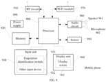
- FIG. 9 is a block diagram illustrating a partial structure of a mobile phone related to a terminal according to an embodiment of the present application. Referring to FIG.
- the mobile phone includes components such as a radio frequency (RF) circuit 910, a memory 920, an input unit 930, a display unit 940, a sensor 950, an audio circuit 960, a wireless fidelity (WiFi) module 970, a processor 980 and a power supply 990.
- RF radio frequency
- FIG. 9 the structure of the mobile phone shown in FIG. 9 does not constitute a limitation to the handset, and may include more or less components than those illustrated, or some components or different components may be combined for arrangement.
- the RF circuit 910 can be used to receive and transmit information.
- the RF circuit 910 includes, but is not limited to, an antenna, at least one amplifier, a transceiver, a coupler, a low noise Amplifier (LNA), a duplexer and such.
- the RF circuitry 910 can also communicate with other devices via wireless communication and the network.
- the above wireless communication may use any communication standard or protocol, including but not limited to Global System of Mobile communication (GSM), General Packet Radio Service (GPRS), Code Division Multiple Access (CDMA), Wideband Code Division Multiple Access (WCDMA), Long Term Evolution (LTE), e-mail, Short Messaging Service (SMS) and such.
- GSM Global System of Mobile communication
- GPRS General Packet Radio Service
- CDMA Code Division Multiple Access
- WCDMA Wideband Code Division Multiple Access
- LTE Long Term Evolution
- SMS Short Messaging Service
- the memory 920 can be used to store software programs and modules, and the processor 980 executes various functional applications and data processing of the mobile phone by running software programs and modules stored in the memory 920.
- the memory 920 may mainly include a program storage area and a data storage area, where the program storage area may store an operating system, an application required for at least one function and such; the data storage area may store data created according to usage of the mobile phone and such.
- the memory 920 can include high speed random access memory, and can also include a non-volatile memory, such as at least one magnetic disk storage device, flash memory device, or other volatile solid state storage devices.
- the input unit 930 can be configured to receive input numeric or character information and to generate key signal inputs related to user settings and function controls of the mobile phone.
- the input unit 930 can include a fingerprint identification module 931 and other input devices 932.
- the fingerprint identification module 931 can collect fingerprint data thereon of the user.
- the input unit 930 may also include other input devices 932.
- other input devices 932 may include, but are not limited to, one or more of a touch screen, a physical keyboard, function keys (such as volume control buttons, switch buttons, etc.), a trackball, a mice, a joystick and such.
- the display unit 940 can be used to display information input by the user or information provided to the user as well as various menus of the mobile phone.
- the display unit 940 can include a display screen 941.
- the display screen 941 can be configured in the form of a liquid crystal display (LCD), an organic light-emitting diode (OLED) and such.
- LCD liquid crystal display
- OLED organic light-emitting diode
- FIG. 9 the Fingerprint identification module 931 and the display screen 941 implement the input and input functions of the mobile phone function as two separate components, in some embodiments, the Fingerprint identification module 931 and the display screen 941 can be integrated to achieve the input and playback functions of the mobile phone.
- the mobile phone may also include at least one type of sensor 950, such as a light sensor, motion sensor, and other sensors.
- the light sensor may include an ambient light sensor and a proximity sensor, where the ambient light sensor may adjust the brightness of the display screen 941 according to the brightness of the ambient light, and the proximity sensor may turn off the display screen 941 and/or backlight when the mobile phone moves to the ear.
- the accelerometer sensor can detect the magnitude of acceleration in all directions (usually three axes), the magnitude and direction of gravity when it is stationary, and it can be used to identify mobile phone gesture applications (such as horizontal and vertical screens switching, related games, magnetometer attitude calibration), vibration recognition related functions (such as pedometer, tapping), etc.; gyroscopes, barometers, hygrometers, thermometers, infrared sensors and other sensors that can be provided for the mobile phone will not be repeated herein.
- mobile phone gesture applications such as horizontal and vertical screens switching, related games, magnetometer attitude calibration
- vibration recognition related functions such as pedometer, tapping
- An audio circuit 960, a speaker 961, and a microphone 962 can provide an audio interface between the user and the mobile phone.
- the audio circuit 960 can transmit the converted electrical data of the received audio data to the speaker 961 for conversion to the sound signal for playing; on the other hand, the microphone 962 converts the collected sound signal into an electrical signal that is then received by the audio circuit 960 for conversion into audio data being played and processed afterwards by the processor 980, and being transmitted to the other mobile phone via the RF circuit 910, or the audio data are stored to the memory 920 for further processing.
- WiFi is a short-range wireless transmission technology
- the mobile phone can help users to send and receive emails, browse web pages, and access streaming media through the WiFi module 970, which provides users with wireless broadband Internet access.
- FIG. 9 illustrates the WiFi module 970, it can be understood that it does not have to be a part of the mobile phone, and can be omitted as needed without changing the essence of the invention.
- the processor 980 is the control center of a mobile phone, which connects various portions of the entire mobile phone using various interfaces and lines, and executes various functions and processes data of the mobile phone by running or executing software programs and/or modules stored in the memory 920, and invoking data stored in the memory 920, so as to overall monitor the mobile phone.
- the processor 980 may include one or more processing units; preferably, the processor 980 may integrate an application processor and a modem processor, where the application processor mainly processes an operating system, a user interface, an application and such, and the modem processor mainly process wireless communications. It will be appreciated that the modem processor described above may also not be integrated into the processor 980.
- the mobile phone also includes a power supply 990 (such as a battery) that supplies power to various components.
- a power supply 990 such as a battery
- the power source can be logically coupled to the processor 980 through a power management system, so as to manage functions such as charging, discharging, and power management through the power management system.
- the mobile phone may further include a camera, a Bluetooth module and such, which will not be repeated herein.
- the process on the terminal side in each step method may be implemented based on the structure of the mobile phone.
- each unit function can be implemented based on the structure of the mobile phone.
- the embodiment of the present application further provides a computer readable storage medium, where the computer readable storage medium stores a computer program for electronic data exchange, where the computer program enables the computer to perform some or all of the steps described by the terminal according to the above method embodiment.
- the embodiment of the present application further provides a computer readable storage medium, where the computer readable storage medium stores a computer program for electronic data exchange, where the computer program enables the computer to perform some or all of the steps described by the network device according to the above method embodiment.
- the embodiment of the present application further provides a computer program product, where the computer program product includes a non-transitory computer readable storage medium, the computer program is operative to enable the computer to perform some or all of the steps described by the terminal according to the above method embodiment.
- the computer program product can be a software installation package.
- the embodiment of the present application further provides a computer program product, where the computer program product includes a non-transitory computer readable storage medium, the computer program is operative to enable the computer to perform some or all of the steps described by the network device according to the above method embodiment.
- the computer program product can be a software installation package.
- the steps of the method or algorithm described in the embodiment of the present application may be implemented in a hardware form, or may be implemented in a form that a processor executes a software instruction.
- the software instruction may be composed of corresponding software modules that may be stored in a random access memory (RAM), a flash memory, a read only memory (ROM), an erasable programmable read only memory (EPROM), an electrically erasable programmable read only memory (EEPROM), a register, a hard disk, a removable hard disk, a compact disc read only (CD-ROM) or any other form of storage medium known in the art.
- An exemplary storage medium is coupled to a processor so as to enable the processor to read information, and to write information to the storage medium.
- the storage medium can also be a part of the processor.
- the processor and the storage medium can be located in an ASIC.
- the ASIC may be located in an access network device, a target network device or a core network device.
- the processor and the storage medium may also exist as discrete components in the access network device, the target network device or the core network device.
- the function described in the embodiments of the present application may be implemented whole or partially by software, hardware, firmware, or any combination thereof.
- the function When the function is implemented by software, it may be implemented in whole or partially in the form of a computer program product.
- the computer program product includes one or more computer instructions. When the computer program instructions are loaded and executed on a computer, the process or function described according to the embodiments of the present application are generated in whole or partially.
- the computer can be a general computer, a dedicated computer, a computer network or other programmable device.
- the computer instruction can be stored in a computer storage medium, or be transferred from one computer storage medium to another computer storage medium, for example, the computer instruction may perform carrying transmission from a website site, computer, server or data center in a wired manner (for example, a coaxial cable, fiber, digital subscriber line (DSL) or a wireless manner (for example, infrared, wireless, microwave, etc.) to another website, computer, server or data center.
- the computer storage medium can be any available media that can be accessed by a computer, or be a data storage device such as a server, a data center that includes one or more available media.
- the available medium may be a magnetic medium (for example, a floppy disk, a hard disk and a magnetic tape), an optical medium (for example, a digital video disc (DVD)), or a semiconductor medium (for example, a solid state disk (SSD)), etc.
- a magnetic medium for example, a floppy disk, a hard disk and a magnetic tape
- an optical medium for example, a digital video disc (DVD)
- a semiconductor medium for example, a solid state disk (SSD)
Landscapes
- Engineering & Computer Science (AREA)
- Signal Processing (AREA)
- Computer Networks & Wireless Communication (AREA)
- Mobile Radio Communication Systems (AREA)
Claims (10)
- Aktivierungsverfahren für Bandbreitenteil (Bandwidth Part, BWP), umfassend:Empfangen, durch ein Endgerät, erster Informationen auf einem ersten Bandbreitenteil (Bandwidth Part, BWP) von einer Netzwerkvorrichtung, wobei die ersten Informationen verwendet werden, um einen zweiten BWP zu aktivieren;Übertragen, durch das Endgerät, von Rückkopplungsantwort-Informationen entsprechend den ersten Informationen innerhalb einer Zeiteinheit nach einer Zeiteinheit, die durch die ersten Informationen belegt wird; undBestimmen, durch das Endgerät, dass der zweite BWP nach einer Zielzeitperiode aktiviert wird, beginnend bei einem Ende der Zeiteinheit, innerhalb welcher die Rückkopplungsantwort-Informationen übertragen werden, wobei die Zeiteinheit, innerhalb welcher die Rückkopplungsantwort-Informationen übertragen werden, durch Konfigurationsinformationen angegeben wird, die von der Netzwerkvorrichtung empfangen werden;wobei eine Dauer der Zielzeitperiode durch die Netzwerkvorrichtung konfiguriert wird.
- Verfahren nach Anspruch 1, wobei ein BWP zum Übertragen der Rückkopplungsantwort-Informationen von dem zweiten BWP verschieden ist.
- Verfahren nach Anspruch 1 oder 2, wobei die Rückkopplungsantwort-Informationen angeben, dass das Endgerät die ersten Informationen korrekt empfängt.
- Verfahren nach einem der Ansprüche 1 bis 3, wobei die ersten Informationen über einen Downlink-Steuerkanal übertragen werden.
- Endgerät (700), umfassend: eine Verarbeitungseinheit (702) und eine Kommunikationseinheit (703), wobei:die Verarbeitungseinheit (702) dazu ausgelegt ist, über die Kommunikationseinheit (703) erste Informationen zu einem ersten Bandbreitenteil (Bandwidth Part, BWP) von einer Netzwerkvorrichtung zu empfangen und Rückkopplungsantwort-Informationen entsprechend den ersten Informationen innerhalb einer Zeiteinheit nach einer Zeiteinheit, die von den ersten Informationen belegt wird, zu übertragen, wobei die ersten Informationen verwendet werden, um einen zweiten BWP zu aktivieren; unddie Verarbeitungseinheit (702) ferner dazu ausgelegt ist zu bestimmen, dass der zweite BWP nach einer Zielzeitperiode aktiviert wird, beginnend bei dem Ende der Zeiteinheit, innerhalb welcher die Rückkopplungsantwort-Informationen übertragen werden, wobei die Zeiteinheit, innerhalb welcher die Rückkopplungsantwort-Informationen übertragen werden, durch Konfigurationsinformationen angegeben wird, die von der Netzwerkvorrichtung empfangen werden; wobei eine Dauer der Zielzeitperiode durch die Netzwerkvorrichtung konfiguriert wird.
- Endgerät (700) nach Anspruch 5, wobei ein BWP zum Übertragen der Rückkopplungsantwort-Informationen von dem zweiten BWP verschieden ist.
- Endgerät (700) nach Anspruch 5 oder 6, wobei die Rückkopplungsantwort-Informationen angeben, dass das Endgerät die ersten Informationen korrekt empfängt.
- Endgerät (700) nach einem der Ansprüche 5 bis 7, wobei die ersten Informationen über einen Downlink-Steuerkanal übertragen werden.
- Netzwerkvorrichtung (800), umfassend: eine Verarbeitungseinheit (802) und eine Kommunikationseinheit (803), wobei:die Verarbeitungseinheit (802) dazu ausgelegt ist, über die Kommunikationseinheit (803) erste Informationen zu einem ersten Bandbreitenteil (Bandwidth Part, BWP) zu übertragen und Rückkopplungsantwort-Informationen entsprechend den ersten Informationen innerhalb einer Zeiteinheit nach einer Zeiteinheit, die von den ersten Informationen belegt wird, zu empfangen, wobei die ersten Informationen verwendet werden, um einen zweiten BWP zu aktivieren; unddie Verarbeitungseinheit (802) ferner dazu ausgelegt ist, gemäß den Rückkopplungsantwort-Informationen zu bestimmen, dass der zweite BWP nach einer Zielzeitperiode aktiviert wird, beginnend bei dem Ende der Zeiteinheit, innerhalb welcher die Rückkopplungsantwort-Informationen übertragen werden, wobei die Zeiteinheit, innerhalb welcher die Rückkopplungsantwort-Informationen übertragen werden, durch Konfigurationsinformationen angegeben wird, die von der Netzwerkvorrichtung empfangen werden; wobei eine Dauer der Zielzeitperiode durch die Netzwerkvorrichtung konfiguriert wird.
- Netzwerkvorrichtung (800) nach Anspruch 9, wobei ein BWP zum Übertragen der Rückkopplungsantwort-Informationen von dem zweiten BWP verschieden ist.
Priority Applications (1)
| Application Number | Priority Date | Filing Date | Title |
|---|---|---|---|
| EP23178869.6A EP4236552B1 (de) | 2017-09-14 | 2017-09-14 | Aktivierungsverfahren für bandbreitenteil und zugehörige produkte |
Applications Claiming Priority (4)
| Application Number | Priority Date | Filing Date | Title |
|---|---|---|---|
| EP17922065.2A EP3493627B1 (de) | 2017-09-14 | 2017-09-14 | Verfahren zur aktivierung eines bandbreitenteils (bwp) und verwandtes produkte |
| PCT/CN2017/101745 WO2019051715A1 (zh) | 2017-09-14 | 2017-09-14 | 带宽部分bwp的激活方法及相关产品 |
| EP23178869.6A EP4236552B1 (de) | 2017-09-14 | 2017-09-14 | Aktivierungsverfahren für bandbreitenteil und zugehörige produkte |
| EP20201307.4A EP3783981B1 (de) | 2017-09-14 | 2017-09-14 | Aktivierungsverfahren für bandbreitenteil und zugehörige produkte |
Related Parent Applications (3)
| Application Number | Title | Priority Date | Filing Date |
|---|---|---|---|
| EP17922065.2A Division EP3493627B1 (de) | 2017-09-14 | 2017-09-14 | Verfahren zur aktivierung eines bandbreitenteils (bwp) und verwandtes produkte |
| EP20201307.4A Division EP3783981B1 (de) | 2017-09-14 | 2017-09-14 | Aktivierungsverfahren für bandbreitenteil und zugehörige produkte |
| EP20201307.4A Division-Into EP3783981B1 (de) | 2017-09-14 | 2017-09-14 | Aktivierungsverfahren für bandbreitenteil und zugehörige produkte |
Publications (3)
| Publication Number | Publication Date |
|---|---|
| EP4236552A2 EP4236552A2 (de) | 2023-08-30 |
| EP4236552A3 EP4236552A3 (de) | 2023-09-27 |
| EP4236552B1 true EP4236552B1 (de) | 2025-04-23 |
Family
ID=65723480
Family Applications (3)
| Application Number | Title | Priority Date | Filing Date |
|---|---|---|---|
| EP17922065.2A Active EP3493627B1 (de) | 2017-09-14 | 2017-09-14 | Verfahren zur aktivierung eines bandbreitenteils (bwp) und verwandtes produkte |
| EP20201307.4A Active EP3783981B1 (de) | 2017-09-14 | 2017-09-14 | Aktivierungsverfahren für bandbreitenteil und zugehörige produkte |
| EP23178869.6A Active EP4236552B1 (de) | 2017-09-14 | 2017-09-14 | Aktivierungsverfahren für bandbreitenteil und zugehörige produkte |
Family Applications Before (2)
| Application Number | Title | Priority Date | Filing Date |
|---|---|---|---|
| EP17922065.2A Active EP3493627B1 (de) | 2017-09-14 | 2017-09-14 | Verfahren zur aktivierung eines bandbreitenteils (bwp) und verwandtes produkte |
| EP20201307.4A Active EP3783981B1 (de) | 2017-09-14 | 2017-09-14 | Aktivierungsverfahren für bandbreitenteil und zugehörige produkte |
Country Status (9)
| Country | Link |
|---|---|
| US (3) | US10833946B2 (de) |
| EP (3) | EP3493627B1 (de) |
| CN (3) | CN112187437B (de) |
| DK (1) | DK3493627T3 (de) |
| ES (1) | ES2841430T3 (de) |
| HU (1) | HUE052922T2 (de) |
| PL (1) | PL3493627T3 (de) |
| PT (1) | PT3493627T (de) |
| WO (1) | WO2019051715A1 (de) |
Families Citing this family (12)
| Publication number | Priority date | Publication date | Assignee | Title |
|---|---|---|---|---|
| PL3493627T3 (pl) * | 2017-09-14 | 2021-03-08 | Guangdong Oppo Mobile Telecommunications Corp., Ltd. | Metoda aktywacji części szerokości pasma (bwp) i produktu pokrewnego |
| EP3685618B1 (de) * | 2017-09-22 | 2022-11-02 | LG Electronics Inc. | Verfahren und vorrichtung zur aktivierung von bandbreitenteilen |
| US10980007B2 (en) * | 2017-09-29 | 2021-04-13 | Samsung Electronics Co., Ltd | Uplink resource configuration method and apparatus in wireless communication system |
| JP7094090B2 (ja) * | 2017-10-20 | 2022-07-01 | シャープ株式会社 | 端末装置、基地局装置、および、通信方法 |
| US10785656B2 (en) * | 2018-01-22 | 2020-09-22 | Qualcomm Incorporated | Bandwidth part switch management |
| US11272540B2 (en) | 2018-08-09 | 2022-03-08 | Ofinno, Llc | Channel access and uplink switching |
| US11272539B2 (en) | 2018-08-09 | 2022-03-08 | Ofinno, Llc | Channel access and bandwidth part switching |
| US10805829B2 (en) * | 2019-02-08 | 2020-10-13 | Cisco Technology, Inc. | BLE-based location services in high density deployments |
| CN112399620B (zh) * | 2019-08-16 | 2022-08-09 | 大唐移动通信设备有限公司 | 一种指示节能信息的方法、基站以及用户终端 |
| CN115462141B (zh) * | 2020-05-15 | 2025-07-29 | Lg电子株式会社 | 用于无线通信的发送/接收信号的方法及其设备 |
| WO2022035643A1 (en) * | 2020-08-10 | 2022-02-17 | Qualcomm Incorporated | Wireless communication using multiple active bandwidth parts |
| CN116073961B (zh) * | 2021-09-16 | 2024-09-24 | Oppo广东移动通信有限公司 | 信息反馈方法、装置、设备及介质 |
Family Cites Families (29)
| Publication number | Priority date | Publication date | Assignee | Title |
|---|---|---|---|---|
| US9019902B2 (en) * | 2008-11-11 | 2015-04-28 | Qualcomm Incorporated | Channel quality feedback in multicarrier systems |
| US10135598B2 (en) * | 2009-06-10 | 2018-11-20 | Qualcomm Incorporated | Joint parameter determination and separate cqi generation reporting for LTE-A multicarrier |
| CN102088433B (zh) * | 2009-12-08 | 2015-01-28 | 中兴通讯股份有限公司 | 多载波系统中分量载波激活去激活的优化方法和系统 |
| CN102149208B (zh) | 2010-02-05 | 2013-11-06 | 华为技术有限公司 | 载波激活相关信息的处理方法、基站及ue |
| CN102378296B (zh) * | 2010-08-12 | 2013-06-05 | 普天信息技术研究院有限公司 | 一种通信系统中的频带切换方法 |
| US9559820B2 (en) * | 2011-02-18 | 2017-01-31 | Qualcomm Incorporated | Feedback reporting based on channel state information reference signal (CSI-RS) groups |
| US9673945B2 (en) * | 2011-02-18 | 2017-06-06 | Qualcomm Incorporated | Implicitly linking aperiodic channel state information (A-CSI) reports to CSI-reference signal (CSI-RS) resources |
| CN103139669A (zh) * | 2011-11-22 | 2013-06-05 | 中兴通讯股份有限公司 | 数据发送方法及系统 |
| CN103974418B (zh) | 2013-01-24 | 2019-04-05 | 中兴通讯股份有限公司 | Dmrs处理方法及装置 |
| US9065811B2 (en) | 2013-04-04 | 2015-06-23 | Ericsson Television Inc. | Methods, apparatus, and computer program products for communicating content files based on destination priority |
| CN106304199A (zh) * | 2015-05-27 | 2017-01-04 | 中兴通讯股份有限公司 | 信道协商方法、站点及系统 |
| CN106255215B (zh) * | 2016-08-05 | 2019-12-10 | 宇龙计算机通信科技(深圳)有限公司 | 通信方法及通信装置 |
| WO2018031664A1 (en) * | 2016-08-10 | 2018-02-15 | Idac Holdings, Inc. | Methods for flexible resource usage |
| US10349403B2 (en) * | 2016-08-25 | 2019-07-09 | Qualcomm Incorporated | Supporting different numerology configurations |
| US10595283B2 (en) * | 2016-11-22 | 2020-03-17 | Samsung Electronics Co., Ltd. | Method and apparatus for transmitting and receiving data of terminal |
| US20210211343A1 (en) * | 2017-05-05 | 2021-07-08 | Telefonaktiebolaget Lm Ericsson (Publ) | Numerology-dependent physical uplink control changnel. structure wireless communication |
| US10505803B2 (en) * | 2017-06-15 | 2019-12-10 | Mediatek Inc. | Power-efficient operation for wider bandwidth |
| CN109309550B (zh) * | 2017-07-26 | 2021-10-29 | 维沃移动通信有限公司 | 一种bwp的控制方法、相关设备及系统 |
| US10673601B2 (en) * | 2017-07-27 | 2020-06-02 | Qualcomm Incorporated | Techniques and apparatuses for bandwidth part management |
| US10687365B2 (en) * | 2017-08-01 | 2020-06-16 | Htc Corporation | Device and method of handling bandwidth parts |
| EP3442304B1 (de) * | 2017-08-07 | 2020-09-23 | HTC Corporation | Verfahren zur handhabung von funkverbindungsfehlern und zugehörige kommunikationsvorrichtung |
| CN109391985B (zh) * | 2017-08-11 | 2020-06-26 | 维沃移动通信有限公司 | 一种资源配置方法、终端及基站 |
| CN111756516B (zh) * | 2017-08-11 | 2021-08-27 | 维沃移动通信有限公司 | 一种bwp的激活控制方法、用户设备及基站 |
| US10575217B2 (en) * | 2017-08-11 | 2020-02-25 | Qualcomm Incorporated | Techniques and apparatuses for managing sounding reference signal (SRS) transmissions in a bandwidth part |
| KR102409304B1 (ko) * | 2017-08-16 | 2022-06-15 | 삼성전자주식회사 | 무선통신시스템에서 단말의 대역폭을 조정하는 방법 및 장치 |
| KR102425072B1 (ko) * | 2017-08-18 | 2022-07-27 | 삼성전자 주식회사 | 무선 통신 시스템에서 단말의 전력 소모 감소를 위한 하향링크 제어채널 설정 방법 및 장치 |
| WO2019049282A1 (ja) * | 2017-09-07 | 2019-03-14 | 株式会社Nttドコモ | ユーザ端末及び無線通信方法 |
| US11019610B2 (en) * | 2017-09-11 | 2021-05-25 | Qualcomm Incorporated | Feedback timing and uplink control information resource management for carrier aggregation activation |
| PL3493627T3 (pl) * | 2017-09-14 | 2021-03-08 | Guangdong Oppo Mobile Telecommunications Corp., Ltd. | Metoda aktywacji części szerokości pasma (bwp) i produktu pokrewnego |
-
2017
- 2017-09-14 PL PL17922065T patent/PL3493627T3/pl unknown
- 2017-09-14 EP EP17922065.2A patent/EP3493627B1/de active Active
- 2017-09-14 PT PT179220652T patent/PT3493627T/pt unknown
- 2017-09-14 WO PCT/CN2017/101745 patent/WO2019051715A1/zh not_active Ceased
- 2017-09-14 HU HUE17922065A patent/HUE052922T2/hu unknown
- 2017-09-14 CN CN202011075510.7A patent/CN112187437B/zh active Active
- 2017-09-14 EP EP20201307.4A patent/EP3783981B1/de active Active
- 2017-09-14 DK DK17922065.2T patent/DK3493627T3/da active
- 2017-09-14 ES ES17922065T patent/ES2841430T3/es active Active
- 2017-09-14 EP EP23178869.6A patent/EP4236552B1/de active Active
- 2017-09-14 CN CN202011074760.9A patent/CN112187435B/zh active Active
- 2017-09-14 CN CN201780050786.XA patent/CN109691200B/zh active Active
-
2019
- 2019-02-28 US US16/288,561 patent/US10833946B2/en active Active
-
2020
- 2020-10-01 US US17/061,090 patent/US11539593B2/en active Active
-
2022
- 2022-11-15 US US18/055,506 patent/US20230076416A1/en not_active Abandoned
Also Published As
| Publication number | Publication date |
|---|---|
| EP3493627A1 (de) | 2019-06-05 |
| US10833946B2 (en) | 2020-11-10 |
| WO2019051715A1 (zh) | 2019-03-21 |
| DK3493627T3 (da) | 2021-01-11 |
| CN109691200B (zh) | 2020-10-30 |
| US20210051072A1 (en) | 2021-02-18 |
| EP3783981A1 (de) | 2021-02-24 |
| ES2841430T3 (es) | 2021-07-08 |
| CN112187437A (zh) | 2021-01-05 |
| EP4236552A3 (de) | 2023-09-27 |
| PL3493627T3 (pl) | 2021-03-08 |
| EP3493627B1 (de) | 2020-11-25 |
| CN112187435A (zh) | 2021-01-05 |
| US20190199592A1 (en) | 2019-06-27 |
| CN112187437B (zh) | 2022-07-15 |
| EP4236552A2 (de) | 2023-08-30 |
| CN109691200A (zh) | 2019-04-26 |
| EP3783981B1 (de) | 2023-12-06 |
| US11539593B2 (en) | 2022-12-27 |
| HUE052922T2 (hu) | 2021-06-28 |
| CN112187435B (zh) | 2022-07-15 |
| PT3493627T (pt) | 2020-12-18 |
| EP3493627A4 (de) | 2019-09-18 |
| US20230076416A1 (en) | 2023-03-09 |
Similar Documents
| Publication | Publication Date | Title |
|---|---|---|
| US20230076416A1 (en) | Activation method for bandwidth part and related products | |
| US11706761B2 (en) | Information transmission method and related product | |
| EP3606210B1 (de) | Kanalpositionsanzeigeverfahren und zugehöriges produkt | |
| EP3614718B1 (de) | Messmeldungsteuerungsverfahren und zugehörige vorrichtungen | |
| EP3565333B1 (de) | Signalübertragungsverfahren und -vorrichtung | |
| US11082940B2 (en) | Uplink timing adjustment method and terminal | |
| EP3528579A1 (de) | Datenübertragungsverfahren, netzwerkseitige vorrichtung und endgerät | |
| TW201906438A (zh) | 數據傳輸方法及相關產品 | |
| HK40015262B (zh) | 信息传输方法及相关产品 |
Legal Events
| Date | Code | Title | Description |
|---|---|---|---|
| PUAI | Public reference made under article 153(3) epc to a published international application that has entered the european phase |
Free format text: ORIGINAL CODE: 0009012 |
|
| STAA | Information on the status of an ep patent application or granted ep patent |
Free format text: STATUS: THE APPLICATION HAS BEEN PUBLISHED |
|
| PUAL | Search report despatched |
Free format text: ORIGINAL CODE: 0009013 |
|
| AC | Divisional application: reference to earlier application |
Ref document number: 3493627 Country of ref document: EP Kind code of ref document: P Ref document number: 3783981 Country of ref document: EP Kind code of ref document: P |
|
| AK | Designated contracting states |
Kind code of ref document: A2 Designated state(s): AL AT BE BG CH CY CZ DE DK EE ES FI FR GB GR HR HU IE IS IT LI LT LU LV MC MK MT NL NO PL PT RO RS SE SI SK SM TR |
|
| AK | Designated contracting states |
Kind code of ref document: A3 Designated state(s): AL AT BE BG CH CY CZ DE DK EE ES FI FR GB GR HR HU IE IS IT LI LT LU LV MC MK MT NL NO PL PT RO RS SE SI SK SM TR |
|
| RIC1 | Information provided on ipc code assigned before grant |
Ipc: H04L 5/00 20060101ALI20230823BHEP Ipc: H04W 72/0453 20230101AFI20230823BHEP |
|
| STAA | Information on the status of an ep patent application or granted ep patent |
Free format text: STATUS: REQUEST FOR EXAMINATION WAS MADE |
|
| 17P | Request for examination filed |
Effective date: 20240301 |
|
| RBV | Designated contracting states (corrected) |
Designated state(s): AL AT BE BG CH CY CZ DE DK EE ES FI FR GB GR HR HU IE IS IT LI LT LU LV MC MK MT NL NO PL PT RO RS SE SI SK SM TR |
|
| GRAP | Despatch of communication of intention to grant a patent |
Free format text: ORIGINAL CODE: EPIDOSNIGR1 |
|
| STAA | Information on the status of an ep patent application or granted ep patent |
Free format text: STATUS: GRANT OF PATENT IS INTENDED |
|
| INTG | Intention to grant announced |
Effective date: 20250124 |
|
| GRAS | Grant fee paid |
Free format text: ORIGINAL CODE: EPIDOSNIGR3 |
|
| GRAA | (expected) grant |
Free format text: ORIGINAL CODE: 0009210 |
|
| STAA | Information on the status of an ep patent application or granted ep patent |
Free format text: STATUS: THE PATENT HAS BEEN GRANTED |
|
| AC | Divisional application: reference to earlier application |
Ref document number: 3493627 Country of ref document: EP Kind code of ref document: P Ref document number: 3783981 Country of ref document: EP Kind code of ref document: P |
|
| AK | Designated contracting states |
Kind code of ref document: B1 Designated state(s): AL AT BE BG CH CY CZ DE DK EE ES FI FR GB GR HR HU IE IS IT LI LT LU LV MC MK MT NL NO PL PT RO RS SE SI SK SM TR |
|
| REG | Reference to a national code |
Ref country code: GB Ref legal event code: FG4D |
|
| REG | Reference to a national code |
Ref country code: CH Ref legal event code: EP |
|
| REG | Reference to a national code |
Ref country code: DE Ref legal event code: R096 Ref document number: 602017089143 Country of ref document: DE |
|
| REG | Reference to a national code |
Ref country code: IE Ref legal event code: FG4D |
|
| REG | Reference to a national code |
Ref country code: NL Ref legal event code: MP Effective date: 20250423 |
|
| PG25 | Lapsed in a contracting state [announced via postgrant information from national office to epo] |
Ref country code: NL Free format text: LAPSE BECAUSE OF FAILURE TO SUBMIT A TRANSLATION OF THE DESCRIPTION OR TO PAY THE FEE WITHIN THE PRESCRIBED TIME-LIMIT Effective date: 20250423 |
|
| REG | Reference to a national code |
Ref country code: AT Ref legal event code: MK05 Ref document number: 1789062 Country of ref document: AT Kind code of ref document: T Effective date: 20250423 |
|
| P01 | Opt-out of the competence of the unified patent court (upc) registered |
Free format text: CASE NUMBER: UPC_APP_5341_4236552/2025 Effective date: 20250829 |
|
| PG25 | Lapsed in a contracting state [announced via postgrant information from national office to epo] |
Ref country code: PT Free format text: LAPSE BECAUSE OF FAILURE TO SUBMIT A TRANSLATION OF THE DESCRIPTION OR TO PAY THE FEE WITHIN THE PRESCRIBED TIME-LIMIT Effective date: 20250825 Ref country code: FI Free format text: LAPSE BECAUSE OF FAILURE TO SUBMIT A TRANSLATION OF THE DESCRIPTION OR TO PAY THE FEE WITHIN THE PRESCRIBED TIME-LIMIT Effective date: 20250423 Ref country code: ES Free format text: LAPSE BECAUSE OF FAILURE TO SUBMIT A TRANSLATION OF THE DESCRIPTION OR TO PAY THE FEE WITHIN THE PRESCRIBED TIME-LIMIT Effective date: 20250423 |
|
| PGFP | Annual fee paid to national office [announced via postgrant information from national office to epo] |
Ref country code: DE Payment date: 20250923 Year of fee payment: 9 |
|
| REG | Reference to a national code |
Ref country code: LT Ref legal event code: MG9D |
|
| PG25 | Lapsed in a contracting state [announced via postgrant information from national office to epo] |
Ref country code: NO Free format text: LAPSE BECAUSE OF FAILURE TO SUBMIT A TRANSLATION OF THE DESCRIPTION OR TO PAY THE FEE WITHIN THE PRESCRIBED TIME-LIMIT Effective date: 20250723 Ref country code: GR Free format text: LAPSE BECAUSE OF FAILURE TO SUBMIT A TRANSLATION OF THE DESCRIPTION OR TO PAY THE FEE WITHIN THE PRESCRIBED TIME-LIMIT Effective date: 20250724 |
|
| PG25 | Lapsed in a contracting state [announced via postgrant information from national office to epo] |
Ref country code: PL Free format text: LAPSE BECAUSE OF FAILURE TO SUBMIT A TRANSLATION OF THE DESCRIPTION OR TO PAY THE FEE WITHIN THE PRESCRIBED TIME-LIMIT Effective date: 20250423 |
|
| PG25 | Lapsed in a contracting state [announced via postgrant information from national office to epo] |
Ref country code: BG Free format text: LAPSE BECAUSE OF FAILURE TO SUBMIT A TRANSLATION OF THE DESCRIPTION OR TO PAY THE FEE WITHIN THE PRESCRIBED TIME-LIMIT Effective date: 20250423 |
|
| PGFP | Annual fee paid to national office [announced via postgrant information from national office to epo] |
Ref country code: GB Payment date: 20250915 Year of fee payment: 9 |
|
| PG25 | Lapsed in a contracting state [announced via postgrant information from national office to epo] |
Ref country code: HR Free format text: LAPSE BECAUSE OF FAILURE TO SUBMIT A TRANSLATION OF THE DESCRIPTION OR TO PAY THE FEE WITHIN THE PRESCRIBED TIME-LIMIT Effective date: 20250423 |
|
| PG25 | Lapsed in a contracting state [announced via postgrant information from national office to epo] |
Ref country code: AT Free format text: LAPSE BECAUSE OF FAILURE TO SUBMIT A TRANSLATION OF THE DESCRIPTION OR TO PAY THE FEE WITHIN THE PRESCRIBED TIME-LIMIT Effective date: 20250423 |
|
| PG25 | Lapsed in a contracting state [announced via postgrant information from national office to epo] |
Ref country code: RS Free format text: LAPSE BECAUSE OF FAILURE TO SUBMIT A TRANSLATION OF THE DESCRIPTION OR TO PAY THE FEE WITHIN THE PRESCRIBED TIME-LIMIT Effective date: 20250723 |
|
| PG25 | Lapsed in a contracting state [announced via postgrant information from national office to epo] |
Ref country code: IS Free format text: LAPSE BECAUSE OF FAILURE TO SUBMIT A TRANSLATION OF THE DESCRIPTION OR TO PAY THE FEE WITHIN THE PRESCRIBED TIME-LIMIT Effective date: 20250823 |
|
| PG25 | Lapsed in a contracting state [announced via postgrant information from national office to epo] |
Ref country code: LV Free format text: LAPSE BECAUSE OF FAILURE TO SUBMIT A TRANSLATION OF THE DESCRIPTION OR TO PAY THE FEE WITHIN THE PRESCRIBED TIME-LIMIT Effective date: 20250423 |
|
| PG25 | Lapsed in a contracting state [announced via postgrant information from national office to epo] |
Ref country code: SM Free format text: LAPSE BECAUSE OF FAILURE TO SUBMIT A TRANSLATION OF THE DESCRIPTION OR TO PAY THE FEE WITHIN THE PRESCRIBED TIME-LIMIT Effective date: 20250423 Ref country code: DK Free format text: LAPSE BECAUSE OF FAILURE TO SUBMIT A TRANSLATION OF THE DESCRIPTION OR TO PAY THE FEE WITHIN THE PRESCRIBED TIME-LIMIT Effective date: 20250423 |
|
| PG25 | Lapsed in a contracting state [announced via postgrant information from national office to epo] |
Ref country code: CZ Free format text: LAPSE BECAUSE OF FAILURE TO SUBMIT A TRANSLATION OF THE DESCRIPTION OR TO PAY THE FEE WITHIN THE PRESCRIBED TIME-LIMIT Effective date: 20250423 |
|
| PG25 | Lapsed in a contracting state [announced via postgrant information from national office to epo] |
Ref country code: EE Free format text: LAPSE BECAUSE OF FAILURE TO SUBMIT A TRANSLATION OF THE DESCRIPTION OR TO PAY THE FEE WITHIN THE PRESCRIBED TIME-LIMIT Effective date: 20250423 |
|
| REG | Reference to a national code |
Ref country code: DE Ref legal event code: R097 Ref document number: 602017089143 Country of ref document: DE |
|
| PG25 | Lapsed in a contracting state [announced via postgrant information from national office to epo] |
Ref country code: SK Free format text: LAPSE BECAUSE OF FAILURE TO SUBMIT A TRANSLATION OF THE DESCRIPTION OR TO PAY THE FEE WITHIN THE PRESCRIBED TIME-LIMIT Effective date: 20250423 |
|
| PG25 | Lapsed in a contracting state [announced via postgrant information from national office to epo] |
Ref country code: IT Free format text: LAPSE BECAUSE OF FAILURE TO SUBMIT A TRANSLATION OF THE DESCRIPTION OR TO PAY THE FEE WITHIN THE PRESCRIBED TIME-LIMIT Effective date: 20250423 |
|
| PLBE | No opposition filed within time limit |
Free format text: ORIGINAL CODE: 0009261 |
|
| STAA | Information on the status of an ep patent application or granted ep patent |
Free format text: STATUS: NO OPPOSITION FILED WITHIN TIME LIMIT |
|
| REG | Reference to a national code |
Ref country code: CH Ref legal event code: L10 Free format text: ST27 STATUS EVENT CODE: U-0-0-L10-L00 (AS PROVIDED BY THE NATIONAL OFFICE) Effective date: 20260304 |
|
| PG25 | Lapsed in a contracting state [announced via postgrant information from national office to epo] |
Ref country code: RO Free format text: LAPSE BECAUSE OF FAILURE TO SUBMIT A TRANSLATION OF THE DESCRIPTION OR TO PAY THE FEE WITHIN THE PRESCRIBED TIME-LIMIT Effective date: 20250423 |
|
| 26N | No opposition filed |
Effective date: 20260126 |
|
| REG | Reference to a national code |
Ref country code: CH Ref legal event code: H13 Free format text: ST27 STATUS EVENT CODE: U-0-0-H10-H13 (AS PROVIDED BY THE NATIONAL OFFICE) Effective date: 20260425 |