EP4236423A1 - Verfahren und vorrichtung zur erfassung von konfigurationsinformationen - Google Patents
Verfahren und vorrichtung zur erfassung von konfigurationsinformationen Download PDFInfo
- Publication number
- EP4236423A1 EP4236423A1 EP21881896.1A EP21881896A EP4236423A1 EP 4236423 A1 EP4236423 A1 EP 4236423A1 EP 21881896 A EP21881896 A EP 21881896A EP 4236423 A1 EP4236423 A1 EP 4236423A1
- Authority
- EP
- European Patent Office
- Prior art keywords
- link
- information
- service information
- quality
- terminal device
- Prior art date
- Legal status (The legal status is an assumption and is not a legal conclusion. Google has not performed a legal analysis and makes no representation as to the accuracy of the status listed.)
- Pending
Links
Images




Classifications
-
- H—ELECTRICITY
- H04—ELECTRIC COMMUNICATION TECHNIQUE
- H04W—WIRELESS COMMUNICATION NETWORKS
- H04W28/00—Network traffic management; Network resource management
- H04W28/16—Central resource management; Negotiation of resources or communication parameters, e.g. negotiating bandwidth or QoS [Quality of Service]
- H04W28/24—Negotiating SLA [Service Level Agreement]; Negotiating QoS [Quality of Service]
-
- H—ELECTRICITY
- H04—ELECTRIC COMMUNICATION TECHNIQUE
- H04W—WIRELESS COMMUNICATION NETWORKS
- H04W24/00—Supervisory, monitoring or testing arrangements
- H04W24/02—Arrangements for optimising operational condition
-
- H—ELECTRICITY
- H04—ELECTRIC COMMUNICATION TECHNIQUE
- H04W—WIRELESS COMMUNICATION NETWORKS
- H04W4/00—Services specially adapted for wireless communication networks; Facilities therefor
- H04W4/70—Services for machine-to-machine communication [M2M] or machine type communication [MTC]
-
- H—ELECTRICITY
- H04—ELECTRIC COMMUNICATION TECHNIQUE
- H04W—WIRELESS COMMUNICATION NETWORKS
- H04W72/00—Local resource management
- H04W72/40—Resource management for direct mode communication, e.g. D2D or sidelink
-
- H—ELECTRICITY
- H04—ELECTRIC COMMUNICATION TECHNIQUE
- H04W—WIRELESS COMMUNICATION NETWORKS
- H04W76/00—Connection management
- H04W76/10—Connection setup
- H04W76/14—Direct-mode setup
-
- H—ELECTRICITY
- H04—ELECTRIC COMMUNICATION TECHNIQUE
- H04W—WIRELESS COMMUNICATION NETWORKS
- H04W88/00—Devices specially adapted for wireless communication networks, e.g. terminals, base stations or access point devices
- H04W88/02—Terminal devices
- H04W88/04—Terminal devices adapted for relaying to or from another terminal or user
Definitions
- Embodiment of the present application relates to the technical field of communication, and in particular to a method and an apparatus for acquiring configuration information.
- a terminal device and a terminal device can communicate directly and transmit data, and this kind of link is called direct link.
- a sending-side terminal device when a sending-side terminal device needs to send data to a receiving-side terminal device, it needs to acquire network configuration information of the direct link between two terminal devices first to complete data transmission.
- one or more relay devices can be introduced between the sending-side terminal device and the receiving-side terminal device in order to improve the transmission coverage, and the relay devices can forward data, thereby expanding a sending range of the sending-side terminal device.
- Embodiments of the present application provide a method and an apparatus for acquiring configuration information, so as to solve the problem of how to acquire network configuration information of links between a terminal device and a relay device, and between relay devices when the relay device is introduced between a sending-side terminal device and a receiving-side terminal device.
- an embodiment of the present application provides a method for acquiring configuration information, including:
- the first device is a first terminal device or a first relay device; and the second device is a second terminal device or a second relay device.
- the first service information includes at least one of the following:
- the configuration information includes at least one of the following:
- the first terminal device is connected with the second terminal device through M links
- the relay device is connected with the second terminal device through N links
- the N links are a subset of the M links, and the N links include the second link, both M and N are positive integers, and M is greater than or equal to N;
- the method further includes: sending, by the relay device, first information to the second device, where the first information includes third quality of service information.
- the second device is the second relay device
- the first information further includes: second service information of the second link.
- the first terminal device is connected with the second terminal device through M links
- the relay device is connected with the second terminal device through N links
- the N links are a subset of the M links, and the N links include the second link, both M and N are positive integers, and M is greater than or equal to N
- the third quality of service information includes quality of service information of each of the M links, or includes quality of service information of each of the N links except the second link.
- the second service information includes at least one of the following:
- an embodiment of the present application provides a method for acquiring configuration information, including:
- the configuration information includes at least one of the following:
- the service information also includes a number of links M and total quality of service information, where the first terminal device is connected with the second terminal device through M links, and M-1 relay devices are included in the M links, M is an integer greater than 1.
- the configuration information further includes: quality of service information of each of the M links.
- the first terminal device is connected with the second terminal device through M links, and the service information further includes at least one of the following:
- the method further includes:
- an apparatus for acquiring configuration information including:
- the first device is a first terminal device or a first relay device; and the second device is a second terminal device or a second relay device.
- the first service information includes at least one of the following:
- the configuration information includes at least one of the following:
- the first terminal device is connected with the second terminal device through M links
- the relay device is connected with the second terminal device through N links
- the N links are a subset of the M links, and the N links include the second link, both M and N are positive integers, and M is greater than or equal to N;
- the sending module is further configured to: send first information to the second device, where the first information includes third quality of service information.
- the second device is the second relay device
- the first information further includes: second service information of the second link.
- the first terminal device is connected with the second terminal device through M links
- the relay device is connected with the second terminal device through N links
- the N links are a subset of the M links, and the N links include the second link, both M and N are positive integers, and M is greater than or equal to N
- the third quality of service information includes quality of service information of each of the M links, or includes quality of service information of each of the N links except the second link.
- the second service information includes at least one of the following:
- an apparatus for acquiring configuration information including:
- the configuration information includes at least one of the following:
- the service information also includes a number of links M and total quality of service information, where the first terminal device is connected with the second terminal device through M links, and M-1 relay devices are included in the M links, M is an integer greater than 1.
- the configuration information further includes: quality of service information of each of the M links.
- the first terminal device is connected with the second terminal device through M links, and the service information further includes at least one of the following:
- the receiving module is further configured to:
- an embodiment of the present application provides a relay device, including at least one processor and a memory;
- an embodiment of the present application provides a terminal device, including at least one processor and a memory;
- an embodiment of the present application provides a computer-readable storage medium, stored computer execution instructions, and a processor, when executing the computer execution instructions, implements the method for acquiring configuration information according to any one of the first aspect or the second aspect.
- a relay device acquires first service information and/or first quality of service information of a first link from a first device, where the first link is a link between the first device and the relay device; then, the relay device sends the first service information and/or second quality of service information to a network device, where the second quality of service information is a subset of the first quality of service information; finally, the relay device acquires configuration information of a second link from the network device, where the second link is a link between the relay device and a second device.
- the relay device is able to acquire the configuration information of the second link with the second device, and the second device is a next device node of the relay device.
- the above scheme can be adopted to acquire configuration information of its next link, thus realizing acquisition of configuration information of all links between the sending-side terminal device and the receiving-side terminal device, and further realizing data transmission between the sending-side terminal device and the receiving-side terminal device.
- Terminal device usually has wireless transceiver function, and the terminal device can be deployed on land, including indoor or outdoor, handheld, wearable or vehicle-mounted; it can also be deployed on the water (such as ships, etc.); it can also be deployed in the air (such as airplanes, balloons and satellites).
- the terminal device can be a mobile phone, a tablet computer (Pad), a computer with wireless transceiver function, a virtual reality (VR) terminal device, an augmented reality (AR) terminal device, wireless terminal device in industrial control, vehicle-mounted terminal device, wireless terminal device in self driving, wireless terminal device in remote medical, wireless terminal device in smart grid, wireless terminal device in transportation safety, wireless terminal device in smart city, wireless terminal device in smart home, wearable terminal device, etc.
- the terminal device involved in the embodiment of the present application can also be referred to as a terminal, a user equipment (UE), an access terminal device, a vehicle-mounted terminal, an industrial control terminal, a UE unit, a UE station, a mobile station, a mobile table, a remote station, a remote terminal device, a mobile device, a LTE terminal device, a wireless communication device, a LTE agent or a LTE apparatus, etc.
- the terminal device can also be fixed or mobile.
- Network device generally has wireless transceiver function, and the network device can be mobile.
- the network device can be a mobile device.
- the network device can be a satellite or a balloon station.
- the satellite can be a low earth orbit (LEO) satellite, a medium earth orbit (MEO) satellite, a geostationary earth orbit (GEO) satellite, a high elliptical orbit (HEO) satellite, etc.
- LEO low earth orbit
- MEO medium earth orbit
- GEO geostationary earth orbit
- HEO high elliptical orbit
- the network device can also be a base station located on land, water and other places, for example, the network device can be a next generation NodeB (gNB) or a next generation-evolved NodeB (ng-eNB).
- gNB next generation NodeB
- ng-eNB next generation-evolved NodeB
- gNB provides user plane function and control plane function of new radio (NR) for UE
- ng-eNB provides user plane function and control plane function of evolved universal terrestrial radio access (E-UTRA) for LTE.
- NR new radio
- E-UTRA evolved universal terrestrial radio access
- gNB and ng-eNB are only names used to indicate base stations supporting 5G network systems, and they are not restrictive.
- the network device can also be a base transceiver station (BTS) in a GSM system or a CDMA system, a nodeB (NB) in a WCDMA system, and an evolved node B (eNB or eNodeB) in an LTE system.
- BTS base transceiver station
- NB nodeB
- eNB or eNodeB evolved node B
- the network device can also be a relay station, an access point, a vehicle-mounted device, a wearable device, a network-side device in a network after 5G or a network device in a future evolved PLMN network, a roadside site unit (RSU), etc.
- a relay station an access point
- a vehicle-mounted device a wearable device
- a network-side device in a network after 5G or a network device in a future evolved PLMN network a roadside site unit (RSU), etc.
- RSU roadside site unit
- Quality of service information represents a series of service requests to be met by the network during data transmission. For example, it can be quantified as performance indicators such as bandwidth, delay, jitter, loss rate, throughput, etc. It is an agreement on information transmission quality.
- QoS information represents a series of service requests to be met by the network during data transmission. For example, it can be quantified as performance indicators such as bandwidth, delay, jitter, loss rate, throughput, etc. It is an agreement on information transmission quality.
- the sending-side terminal device needs to transmit data to the receiving-side terminal device
- there will exist total quality of service information which indicates a service request that needs to be met by the sending-side terminal device when transmitting data to the receiving-side terminal device.
- the relay device may be introduced between the sending-side terminal device and the receiving-side terminal device, and multiple links are involved, the quality of service information on each link can be acquired based on the total quality of service information.
- Traffic pattern information traffic pattern, which mainly includes period, offset and packet size of the service.
- the service refers to a service that the sending-side terminal device transmits data to the receiving-side terminal device.
- Configured grant configuration information refers to the process that between two devices, when a device authorizes the other device once through activation, the other device will always use the resources specified by the previous authorization for transmission in case deactivation is not received.
- Common configured grant includes uplink configured grant, which is configured grant between the base station and the terminal device. In the embodiments of the present application, data transmission between a terminal device and a relay device or between relay devices is involved, and the configured grant configuration information can be used for configured grant between the terminal device and the relay device, or between the relay devices.
- Bearer configuration information refers to the protocol stack configuration information used for data transmission between two devices.
- data is transmitted through bearers, and different bearers have different protocol stack configurations.
- the user plane protocol stack usually includes SDAP (Service Data Adaptation Protocol) layer, PDCP (packet data convergence protocol) layer, RLC (Radio Link control) layer and MAC (Media Access Control) layer, and the bearer configuration information will configure each layer respectively to meet data transmission requirements.
- SDAP Service Data Adaptation Protocol
- PDCP Packet data convergence protocol
- RLC Radio Link control
- MAC Media Access Control
- Relay device is also known as relay, is a transmission path between two switching centers.
- a relay device in order to improve the transmission coverage, a relay device can be introduced between the sending terminal and the receiving terminal, and the relay device can forward received data to the receiving terminal, thereby expanding sending range of the sending terminal.
- a relay device can be introduced between a base station and a terminal device, and the relay device is responsible for forwarding the data of the terminal device to the base station or forwarding the data of the base station to the terminal device.
- SSL communication technology also known as direct communication technology of things, is a communication technology that is different from that of an ordinary wireless cellular network.
- a terminal device communicates with a network device, and the link between the terminal device and the network device is called Uplink or Downlink, and an interface is called Uu interface.
- Uu interface In the direct communication between things, terminal devices communicate directly with each other.
- the link between the terminal devices is called direct link, an interface is called PC5 interface, and the sidelink can also be called direct link.
- FIG. 1 is a schematic diagram of uplink, downlink and sidelink provided by an embodiment of the present application.
- a base station 10 a terminal 11 and a terminal 12 is included, where there are uplink and downlink between the base station 10 and the terminal 11.
- the base station 10 can send downlink data to the terminal 11 through the downlink, and the terminal 11 can send uplink data to the base station 10 through the uplink.
- the terminal 11 can send data to the terminal 12, and the terminal 12 can also send data to the terminal 11.
- sidelink was introduced to realize the direct communication between terminal devices with relatively close distance, and the data does not need to be forwarded through the base station, thus reducing the transmission delay.
- a sidelink relay is designed based on the introduction of sidelink.
- the relay used the technology of uplink and downlink communication between the relay and the terminal device, while the sidelink relay use the sidelink technology in the link between the relay device and the terminal device.
- FIG. 2 is a schematic diagram of introducing a relay device between terminal devices provided by an embodiment of the present application. As shown in FIG. 2 , one or more relay devices can be introduced between two terminal devices.
- a relay device 22 is introduced between the terminal device 21 and the terminal device 23.
- a plurality of relay devices are introduced between the terminal device 24 and the terminal device 27, and FIG 2 illustrates the situation of two relay devices, including the relay device 25 and the relay device 26.
- the number of introduced relay devices can be three, four, etc., and the number is not limited.
- FIG. 3 is a schematic diagram of an application scenario provided by an embodiment of the present application. As shown in FIG. 3 , it includes a network device 31, a network device 32 and a network device 33, as well as a first terminal device 34, a second terminal device 37 and k relay devices, where k is a positive integer. FIG. 3 illustrates two relay devices, namely relay device 35 and relay device 36, respectively.
- the network device 31 can communicate with the first terminal device 34, for example, the network device 31 can be a serving base station of the first terminal device 34.
- the network device 32 can communicate with the relay device 35, for example, the network device 32 can be the serving base station of the relay device 35;
- the network device 33 can communicate with the relay device 36, for example, the network device 33 can be a serving base station of the relay device 36, and so on.
- the serving base station of each terminal device and the serving base station of each relay device may be different base stations from each other, or the same base station, which is not limited by the embodiment of the present application.
- the first terminal device 34 is a sending-side terminal device
- the second terminal device 37 is a receiving-side terminal device.
- the sending-side terminal device and the receiving-side terminal device are determined based on the actions performed by two terminal devices in one data transmission, and a terminal sending data is the sending-side terminal device and a terminal receiving data is the receiving-side terminal device.
- the second terminal device 37 needs to send data to the first terminal device 34
- the second terminal device 37 is the sending-side terminal device and the first terminal device 34 is the receiving-side terminal device.
- relay devices are set to expand the range of data transmission by terminal devices, and the number of relay devices between the first terminal device 34 and the second terminal device 37 is related to the distance between the first terminal device 34 and the second terminal device 37, signal quality and other factors.
- the first terminal device 34 When the first terminal device 34 determines that it needs to transmit data to the second terminal device 37, the first terminal device 34 needs to establish a link connection with the second terminal device 37 first. Specifically, the first terminal device 34 can send some control signaling outwardly. At this time, the relay device 35 receives the control signaling, and a link connection can be established between the first terminal device 34 and the relay device 35. The relay device 35 will continue to send control signaling outwardly, and after the control signaling is transmitted to the relay device 36, a link connection will be established between the relay device 35 and the relay device 36. Then the relay device 36 can send control signaling, and at this time, the second terminal device 37 receives the control signaling and establishes a link connection with the relay device 36. Therefore, a link connection is successfully established between the first terminal device 34 and the second terminal device 37 through the relay device 35 and the relay device 36.
- the first terminal device 34 and the second terminal device 37 cannot transmit data directly, and it is necessary to acquire network configuration information of the link between the first terminal device 34 and the second terminal device 37.
- the first terminal device 34 When there is no relay device between the first terminal device 34 and the second terminal device 37, the first terminal device 34 is directly connected with the second terminal device 37 through a direct link. At this time, the serving base station of the first terminal device 34 can send the network configuration information of the direct link to the first terminal device 34, and the first terminal device 34 can send data to the second network device 37 based on the network configuration information of the direct link.
- the first terminal device 34 and the second terminal device 37 are connected through multiple links, and data transmission needs to be forwarded from the first terminal device 34 through the relay device before reaching the second terminal device 37.
- an embodiment of the present application provides a scheme for acquiring network configuration information.
- FIG. 4 is a flowchart diagram of a method for acquiring configuration information provided by an embodiment of the present application. As shown in FIG. 4 , the method may include: S41: a relay device acquires first service information and/or first quality of service information of a first link from a first device, where the first link is a link between the first device and the relay device.
- the application scenario of the embodiment of the present application is that a connection is established between a sending-side terminal device and a receiving-side terminal device through at least one relay device, and the execution body of the method is any relay device between the sending-side terminal device and the receiving-side terminal device.
- the first device is a previous device node of the relay device, and the link established between the first device and the relay device is the first link.
- the first device may be the sending-side terminal device or another relay device.
- the first device can send the first service information and/or the first quality of service information of the first link to the relay device.
- the first service information may include, for example, a traffic pattern, configured grant configuration information of the first link, identification information of the first link, and the like.
- the first quality of service information may be quality of service information of all links between the sending-side terminal device and the receiving-side terminal device, or quality of service information of all links after the first link, and so on.
- the relay device sends the first service information and/or second quality of service information to a network device, where the second quality of service information is a subset of the first quality of service information.
- the relay device After receiving the first service information and/or the first quality of service information of the first link from the first device, the relay device needs to send the first service information and/or the second quality of service information to the network device, where the network device here is a network device that has established a communication connection with the relay device, such as a serving base station for the relay device.
- the relay device receives the first service information from the first device, it can directly forward the first service information to the network device. If the relay device receives the first quality of service information from the first device, it can send the second quality of service information to the network device, where the second quality of service information is a subset of the first quality of service information.
- the second quality of service information must include quality of service information of the second link, and may selectively include quality of service information of other links.
- the second link is a link after the first link, therefore, the first quality of service information must include the quality of service information of the second link, and the second quality of service information is a subset of the first quality of service information.
- the relay device acquires configuration information of a second link from the network device, where the second link is a link between the relay device and a second device.
- the network device After the network device acquires the first service information and/or the second quality of service information, it can also configure the second link based on the first service information and/or the second quality of service information, and send the configuration information of the second link to the relay device.
- the second link is a link between the relay device and the second device, where the second device can be the receiving-side terminal device or other relay devices. After acquiring the configuration information of the second link, the data can be transmitted from the relay device to the second device.
- a relay device acquires first service information and/or first quality of service information of a first link from a first device, where the first link is a link between the first device and the relay device; then, the relay device sends the first service information and/or second quality of service information to a network device, where the second quality of service information is a subset of the first quality of service information; finally, the relay device acquires configuration information of a second link from the network device, where the second link is a link between the relay device and a second device.
- the relay device is able to acquire the configuration information of the second link with the second device, and the second device is a next device node of the relay device.
- the above scheme can be adopted to acquire configuration information of its next link, thus realizing acquisition of configuration information of all links between the sending-side terminal device and the receiving-side terminal device, and further realizing data transmission between the sending-side terminal device and the receiving-side terminal device.
- the first device is a previous device node of the relay device
- the second device is a posterior device node of the relay device.
- its corresponding first device may be the first terminal device, that is, the sending-side terminal device, or it may be another relay device, that is, a first relay device
- its corresponding second device may be the second terminal device, that is, the receiving-side terminal device, or other relay device, that is, a second relay device.
- the contents included in the first service information or the first quality of service information may be different for different situations of the first device, and the contents included in the configuration information may be different for different situations of the second device. This will be explained in detail below.
- FIG. 5 is a schematic diagram 1 for acquiring configuration information provided by an embodiment of the present application. As shown in FIG. 5 , it includes a network device 51, a first terminal device 52, a relay device 53 and a second relay device 54. FIG. 5 illustrates a case where the first device is the first terminal device 52 and the second device is the second relay device 54. The link between the first terminal device 52 and the relay device 53 is a first link, and the link between the relay device 53 and the second relay device 54 is a second link.
- the first terminal device 52 sends first service information and/or first quality of service information to the relay device 53, where the first service information includes one or more of configured grant configuration information of the first link, traffic pattern information and identification information of the first link.
- the relay device 53 sends the first service information and/or second quality of service information to the network device 51. If the first terminal device is connected with the second terminal device through M links, and the relay device is connected with the second terminal device through N links, and the N links are a subset of the M links, then the N links include the second link, both M and N are positive integers, and M is greater than or equal to N.
- the first quality of service information includes quality of service information of each of the M links, or includes quality of service information of each of the N links;
- the second quality of service information is the first quality of service information, or the second quality of service information is quality of service information of the second link.
- the network device 51 can determine the configuration information based on the first service information and/or the second quality of service information, and send the configuration information to the relay device 53, where the configuration information includes at least one of bearer configuration information of the second link and configured grant configuration information of the second link.
- the relay device 53 can send first information to the second relay device 54.
- the first information includes third quality of service information and second service information of the second link.
- the third quality of service information includes quality of service information of each of the M links, or includes quality of service information of each of the N links except the second link.
- the second service information includes one or more of configured grant configuration information of the second link, traffic pattern information and identification information of the second link.
- FIG. 6 is a schematic diagram 2 for acquiring configuration information provided by an embodiment of the present application. As shown in FIG. 6 , it includes a network device 61, a first terminal device 62, a relay device 63 and a second terminal device 64. FIG. 6 illustrates a case where the first device is a first terminal device 62 and the second device is a second terminal device 64. The link between the first terminal device 62 and the relay device 63 is the first link, and the link between the relay device 63 and the second terminal device 64 is the second link.
- the first terminal device 62 sends first service information and/or first service quality information to the relay device 63, and the relay device 63 sends the first service information and/or second service quality information to the network device 61.
- the network device 61 After receiving the first service information and/or the second service quality information, the network device 61 can determine configuration information based on the first service information and/or the second service quality information, and send the configuration information to the relay device 63. The relay device 63 can then send first information to the second terminal device 64.
- the first service information, the first service quality information, the second service quality information, the configuration information and the third service quality information all correspond to the contents included in the first service information, the first service quality information, the second service quality information, the configuration information and the third service quality information in the scenario illustrated in FIG. 5 and are identical to the same.
- the first information only includes the third quality of service information, and does not include the second service information of the second link.
- FIG. 7 is a schematic diagram 3 for acquiring configuration information provided by an embodiment of the present application. As shown in FIG. 7 , it includes a network device 71, a first relay device 72, a relay device 73 and a second terminal device 74. FIG. 7 illustrates a case where the first device is the first relay device 72 and the second device is the second terminal device 74. The link between the first relay device 72 and the relay device 73 is the first link, and the link between the relay device 73 and the second terminal device 74 is the second link.
- the first relay device 72 sends first service information and/or first quality of service information to the relay device 73, and the relay device 73 sends the first service information and/or second quality of service information to the network device 71.
- the network device 71 After receiving the first service information and/or the second service quality information, the network device 71 can determine configuration information based on the first service information and/or the second service quality information, and send the configuration information to the relay device 73. The relay device 73 can then send first information to the second terminal device 74.
- the first service information, the first quality of service information, the second quality of service information, the configuration information and the first information all correspond to contents included in the first service information, the first quality of service information, the second quality of service information, the configuration information and the first information in the scenario illustrated in FIG. 6 and are identical to the same, and will not be repeated here.
- FIG. 8 is a schematic diagram 4 for acquiring configuration information provided by an embodiment of the present application. As shown in FIG. 8 , it includes a network device 81, a first relay device 82, a relay device 83 and a second relay device 84. FIG. 8 illustrates a case where the first device is the first relay device 82 and the second device is the second relay device 84. The link between the first relay device 82 and the relay device 83 is the first link, and the link between the relay device 83 and the second relay device 84 is the second link.
- the first relay device 82 sends first service information and/or first quality of service information to the relay device 83, and the relay device 83 sends the first service information and/or second quality of service information to the network device 81.
- the network device 81 can determine configuration information based on the first service information and/or the second service quality information, and send the configuration information to the relay device 83.
- the relay device 83 can then send first information to the second relay device 84.
- the first service information, the first quality of service information, the second quality of service information, the configuration information and the first information all correspond to the contents included in first service information, the first quality of service information, the second quality of service information, the configuration information and the first information in the scenario illustrated in FIG. 5 and are identical to the same, and will not be repeated here.
- FIG. 9 is a flow diagram of a method for acquiring configuration information provided by an embodiment of the present application. As shown in FIG. 9 , the method may include: S91, a first terminal device sends service information to a network device, where the service information includes traffic pattern information.
- the execution body of the method in the embodiment of the present application is the first terminal device, which is a sending-side terminal device, and the network device is a serving base station of the first terminal device. Initially, the first terminal device sends service information to the network device, and the network device receives the service information, which includes traffic pattern information.
- the first terminal device receives configuration information of a first link from the network device, where the first link is a link between the first terminal device and a relay device.
- the network device configures the first link based on the service information to obtain the configuration information of the first link, where the first link is a link between the first terminal device and the relay device.
- the configuration information includes at least one of bearer configuration information of the first link and configured grant configuration information of the first link.
- the splitting of the total quality of service information can be completed by the first terminal device or by the network device.
- the service information When the splitting of the total quality of service information is completed by the network equipment, the service information also includes a number of links M and total quality of service information, where the first terminal device is connected with the second terminal device through M links, and M-1 relay devices are included in the M links, M is an integer greater than 1.
- the configuration information also includes quality of service information of each of the M links.
- the first terminal device When the splitting of the total quality of service information is completed by the first terminal device, the first terminal device first acquires total quality of service information and the number of links M, and then acquires the quality of service information of each of the M links based on the total quality of service information and the M.
- the service information may include the quality of service information of each of the M links, and may also include the quality of service information of the first link.
- the configuration information also includes the quality of service information of each of the M links.
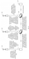
- FIG. 10 is a schematic diagram 1 for acquiring configuration information provided by an embodiment of the present application. As shown in FIG. 10 , it includes a network device 101, a network device 102, a network device 103, a first terminal device 104, a relay device 105, a relay device 106 and a second terminal device 107.
- the network device 101 can be a serving base station of the first terminal device 104
- the network device 102 can be a serving base station of the relay device 105
- the network device 103 can be a serving base station of the relay device 106.
- the first terminal device 104 and the second terminal device 107 are connected through one or more relay devices, and two relay devices are exemplified in FIG. 10 .
- the link between the first terminal device 104 and the relay device 105 is link 1
- the link between the relay device 105 and the relay device 106 is link 2
- the link between the relay device 106 and the second terminal device 107 is link 3.
- Step 1 the first terminal device 104 sends end-to-end QoS information, traffic pattern information and a number of hops of communication through relay to the network device 101.
- the number of hops of communication through relay is the number of the relay devices.
- the number of hops of communication through relay is 2.
- the end-to-end QoS information is the total quality of service information in the above embodiment. After acquiring the total quality of service information and the number of hops of communication through relay, the network device 101 can allocate the QoS information of each link to the respective link. Therefore, in FIG. 10 illustrates that the total quality of service information is split by the network device 101.
- Step 2 the network device 101 sends the QoS information, bearer configuration information of link 1 and configured grant configuration information of link 1 to the first terminal device 104.
- the QoS information is QoS information on each link, where three links are included in FIG. 9 , therefore, the QoS information here includes the QoS information of link 1, QoS information of link 2 and QoS information of link 3.
- Step 3 the first terminal device 104 sends the QoS information, the configured grant configuration information of link 1, the traffic pattern information and identification information of link 1 to the relay device 105.
- the QoS information may be the QoS information on each link or QoS information on other links except link 1.
- the QoS information may include the QoS information of link 2 and the QoS information of link 3.
- the identification information of link 1 is used to indicate which link is link 1.
- Step 4 the relay device 105 sends the QoS information, the configured grant configuration information of link 1, the traffic pattern information and the identification information of link 1 to the network device 102.
- the QoS information may be the QoS information of each link or only the QoS information of link 2.
- Step 5 the network device 102 sends bearer configuration information and configured grant configuration information of link 2 to the relay device 105.
- Step 6 the relay device 105 sends the QoS information, the configured grant configuration information of link 2, the traffic pattern information and identification information of link 2 to the relay device 106.
- the QoS information may be the QoS information of each link or QoS information of other links except link 1 and link 2.
- the QoS information may be the QoS information of link 3.
- the identification information of link 2 is used to indicate which link is link 2.
- Step 7 the relay device 106 sends the QoS information, the traffic pattern information, the configured grant configuration information of link 2 and the identification information of link 2 to the network device 103.
- Step 8 the network device 103 sends bearer configuration information of link 3 and configured grant configuration information of link 3 to the relay device 106.
- Step 9 the relay device 106 sends the QoS information to the second terminal device 107.
- the QoS information may be the QoS information of each link or only the QoS information of link 3.
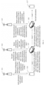
- FIG. 11 is a schematic diagram 2 for acquiring configuration information provided by an embodiment of the present application. As shown in FIG. 11 , it includes a network device 111, a network device 112, a network device 113, a first terminal device 114, a relay device 115, a relay device 116 and a second terminal device 117.
- the network device 111 can be a serving base station of the first terminal device 114
- the network device 112 can be a serving base station of the relay device 115
- the network device 113 can be a serving base station of the relay device 116.
- the first terminal device 114 and the second terminal device 117 are connected by one or more relay devices, and two relay devices are illustrated in FIG. 11 .
- the link between the first terminal device 114 and the relay device 115 is link 1
- the link between the relay device 115 and the relay device 116 is link 2
- the link between the relay device 116 and the second terminal device 117 is link 3.
- Step 1 the first terminal device 114 sends QoS information and traffic pattern information to the network device 111.
- the QoS information can be the QoS information of each link or just the QoS information of link 1.
- FIG. 11 illustrates that the total quality of service information is split by the first terminal device 114. After acquiring the total quality of service information and the number of hops of communication through relay, the first terminal device 114 can allocate the QoS information of each link to the respective link.
- Step 2 the network device 111 sends bearer configuration information of link 1 and configured grant configuration information of link 1 to the first terminal device 114.
- the QoS information is the QoS information of each link, which includes three links in FIG. 9 , therefore, the QoS information here includes the QoS information of link 1, the QoS information of link 2 and the QoS information of link 3.
- Step 3 the first terminal device 114 sends the QoS information, the configured grant configuration information of link 1, the traffic pattern information and identification information of link 1 to the relay device 115.
- the QoS information may be the QoS information of each link or the QoS information of other links except link 1.
- the QoS information may include the QoS information of link 2 and the QoS information of link 3.
- the identification information of link 1 is used to indicate which link is link 1.
- Step 4 the relay device 115 sends the QoS information, the configured grant configuration information of link 1, the traffic pattern information and the identification information of link 1 to the network device 112.
- the QoS information may be the QoS information of each link or only the QoS information of link 2.
- Step 5 the network device 112 sends bearer configuration information of link 2 and configured grant configuration information of link 2 to the relay device 115.
- Step 6 the relay device 115 sends the QoS information, the configured grant configuration information of link 2, the traffic pattern information and identification information of link 2 to the relay device 116.
- the QoS information may be the QoS information of each link or the QoS information of other links except link 1 and link 2.
- the QoS information may be the QoS information of link 3.
- the identification information of link 2 is used to indicate which link is link 2.
- Step 7 the relay device 116 sends the QoS information, the traffic pattern information, the configured grant configuration information of tlink 2 and the identification information of link 2 to the network device 113.
- Step 8 the network device 113 sends bearer configuration information of link 3 and configured grant configuration information of link 3 to the relay device 116.
- Step 9 the relay device 116 sends the QoS information to the second terminal device 117.
- the QoS information may be the QoS information of each link or only the QoS information of link 3.
- FIG. 12 is a schematic structural diagram of an apparatus for acquiring configuration information provided by an embodiment of the present application. As shown in FIG. 12 , the apparatus for acquiring configuration information 120 includes:
- the first device is a first terminal device or a first relay device; and the second device is a second terminal device or a second relay device.
- the first service information includes at least one of the following:
- the configuration information includes at least one of the following:
- the first terminal device is connected with the second terminal device through M links
- the relay device is connected with the second terminal device through N links
- the N links are a subset of the M links, and the N links include the second link, both M and N are positive integers, and M is greater than or equal to N;
- the sending module 122 is further configured to: send first information to the second device, where the first information includes third quality of service information.
- the second device is the second relay device
- the first information further includes: second service information of the second link.
- the first terminal device is connected with the second terminal device through M links
- the relay device is connected with the second terminal device through N links
- the N links are a subset of the M links, and the N links include the second link, both M and N are positive integers, and M is greater than or equal to N
- the third quality of service information includes quality of service information of each of the M links, or includes quality of service information of each of the N links except the second link.
- the second service information includes at least one of the following:
- FIG. 13 is a schematic structural diagram of an apparatus for acquiring configuration information provided by an embodiment of the present application. As shown in FIG. 13 , the apparatus for acquiring configuration information 130 includes:
- the configuration information includes at least one of the following:
- the service information also includes a number of links M and total quality of service information, where the first terminal device is connected with the second terminal device through M links, and M-1 relay devices are included in the M links, M is an integer greater than 1.
- the configuration information further includes: quality of service information of each of the M links.
- the first terminal device is connected with the second terminal device through M links, and the service information further includes at least one of the following:
- the receiving module 132 is further configured to:
- FIG. 14 is a schematic structural diagram of a relay device provided by an embodiment of the present application.
- the relay device 140 may include a transceiver 141, a memory 142, and a processor 143.
- the transceiver 141 may include a transmitter and/or a receiver.
- the transmitter can also be called as a sender, a transmitting device, a sending port or a sending interface and the like, and the receiver can also be called as a receiver, a receiving device, a receiving port or a receiving interface and the like.
- the transceiver 141, the memory 142, and the processor 143 are interconnected by a bus 144.
- the memory 142 is used to store program instructions; and the processor 143 is used to execute the program instructions stored in the memory to cause the relay device 140 to execute any of the methods for acquiring configuration information shown above.
- the receiver of the transceiver 141 can be used to perform the receiving function of the relay device in the above method for acquiring configuration information.
- FIG. 15 is a schematic structural diagram of a terminal device provided by an embodiment of the present application.
- the terminal device 150 may include a transceiver 151, a memory 152, and a processor 153.
- the transceiver 151 may include a transmitter and/or a receiver.
- the transmitter can also be called as a sender, a transmitting device, a sending port or a sending interface and the like, and the receiver can also be called as a receiver, a receiving device, a receiving port or a receiving interface and the like.
- the transceiver 151, the memory 152, and the processor 153 are interconnected by a bus 154.
- the memory 152 is used to store program instructions
- the processor 153 is used to execute the program instructions stored in the memory to cause the terminal device 150 to execute any of the methods for acquiring configuration information shown above.
- the receiver of the transceiver 151 can be used to perform the receiving function of the terminal device in the above methods for acquiring configuration information.
- An embodiment of the present application provides a computer-readable storage medium, the computer-readable storage medium stores computer execution instructions, and a processor, when executing the computer execution instructions, implements the above method for acquiring the configuration information.
- An embodiment of the present application also provide a computer program product which can be executed by a processor, and when the computer program product is executed, any one of the above method for acquiring configuration information executed by the terminal device is implemented.
- the transmission device, the computer-readable storage medium and the computer program product of the embodiments of the present application can execute the above method for acquiring configuration information executed by the network device, and the specific implementation process and beneficial effects thereof are described above, and are not described here.
- the disclosed systems, apparatuses and methods can be realized in other ways.
- the apparatuses embodiment described above is only exemplary.
- the division of the units is only a logical function division.
- the mutual coupling or direct coupling or communication connection shown or discussed can be indirect coupling or communication connection through some interfaces, apparatuses or units, which can be electrical, mechanical or other forms.
- the units described as separate components may or may not be physically separated, and the components displayed as units may or may not be physical units, that is, they may be located in one place or distributed to multiple network units. Some or all of the units can be selected according to actual needs to achieve the purpose of the embodiments.
- each functional unit in each embodiment of the present application can be integrated into one processing unit, or each unit can exist physically alone, or two or more units can be integrated into one unit.
- the above integrated units can be realized in the form of hardware or software functional units.
- the aforementioned computer program can be stored in a computer-readable storage medium.
- the computer program when executed by a processor, implements the steps including the above method embodiments; the aforementioned storage media include ROM, RAM, magnetic disk or optical disk and other media that can store program codes.
Landscapes
- Engineering & Computer Science (AREA)
- Quality & Reliability (AREA)
- Computer Networks & Wireless Communication (AREA)
- Signal Processing (AREA)
- Mobile Radio Communication Systems (AREA)
Applications Claiming Priority (2)
| Application Number | Priority Date | Filing Date | Title |
|---|---|---|---|
| CN202011139267.0A CN114390558B (zh) | 2020-10-22 | 2020-10-22 | 配置信息获取方法及装置 |
| PCT/CN2021/123333 WO2022083478A1 (zh) | 2020-10-22 | 2021-10-12 | 配置信息获取方法及装置 |
Publications (2)
| Publication Number | Publication Date |
|---|---|
| EP4236423A1 true EP4236423A1 (de) | 2023-08-30 |
| EP4236423A4 EP4236423A4 (de) | 2024-04-24 |
Family
ID=81193197
Family Applications (1)
| Application Number | Title | Priority Date | Filing Date |
|---|---|---|---|
| EP21881896.1A Pending EP4236423A4 (de) | 2020-10-22 | 2021-10-12 | Verfahren und vorrichtung zur erfassung von konfigurationsinformationen |
Country Status (4)
| Country | Link |
|---|---|
| US (1) | US20240031874A1 (de) |
| EP (1) | EP4236423A4 (de) |
| CN (1) | CN114390558B (de) |
| WO (1) | WO2022083478A1 (de) |
Families Citing this family (3)
| Publication number | Priority date | Publication date | Assignee | Title |
|---|---|---|---|---|
| CN115361749B (zh) * | 2022-08-18 | 2025-06-17 | 维沃移动通信有限公司 | 数据通信方法、装置、电子设备和可读存储介质 |
| CN119384818A (zh) * | 2022-09-23 | 2025-01-28 | Oppo广东移动通信有限公司 | 通信方法、装置、设备、存储介质及程序产品 |
| CN121488583A (zh) * | 2023-08-10 | 2026-02-06 | Oppo广东移动通信有限公司 | 无线通信的方法和通信设备 |
Family Cites Families (10)
| Publication number | Priority date | Publication date | Assignee | Title |
|---|---|---|---|---|
| CN102164385B (zh) * | 2010-02-21 | 2015-01-07 | 华为技术有限公司 | 切换方法和中继节点 |
| CN106211026B (zh) * | 2014-12-22 | 2019-05-24 | 中兴通讯股份有限公司 | 一种实现设备直通中继选择的方法、网络控制节点及用户设备 |
| CN107637162B (zh) * | 2015-05-14 | 2022-05-10 | 苹果公司 | Ue到网络中继发起和配置 |
| CN108668351B (zh) * | 2017-03-27 | 2021-06-08 | 上海诺基亚贝尔股份有限公司 | 通信方法和设备 |
| CN107483337A (zh) * | 2017-07-31 | 2017-12-15 | 郑州云海信息技术有限公司 | 确定路径的方法及其网络设备 |
| CN108207036B (zh) * | 2017-09-30 | 2022-07-12 | 中兴通讯股份有限公司 | 一种半持久调度的方法及装置 |
| CN110830954B (zh) * | 2018-08-10 | 2021-02-12 | 电信科学技术研究院有限公司 | 一种直接链路通信的方法、终端及网络设备 |
| US11224007B2 (en) * | 2018-11-19 | 2022-01-11 | Huawei Technologies Co., Ltd. | System and method for supporting sidelink radio bearers |
| WO2020164741A1 (en) * | 2019-02-15 | 2020-08-20 | Huawei Technologies Co., Ltd. | Communication devices and methods for providing multihop transmission |
| CN110602801B (zh) * | 2019-08-09 | 2022-04-05 | 北京紫光展锐通信技术有限公司 | 链路配置方法及装置 |
-
2020
- 2020-10-22 CN CN202011139267.0A patent/CN114390558B/zh active Active
-
2021
- 2021-10-12 US US18/033,214 patent/US20240031874A1/en active Pending
- 2021-10-12 EP EP21881896.1A patent/EP4236423A4/de active Pending
- 2021-10-12 WO PCT/CN2021/123333 patent/WO2022083478A1/zh not_active Ceased
Also Published As
| Publication number | Publication date |
|---|---|
| CN114390558A (zh) | 2022-04-22 |
| CN114390558B (zh) | 2023-07-25 |
| US20240031874A1 (en) | 2024-01-25 |
| WO2022083478A1 (zh) | 2022-04-28 |
| EP4236423A4 (de) | 2024-04-24 |
Similar Documents
| Publication | Publication Date | Title |
|---|---|---|
| US12568394B2 (en) | Communication method and apparatus | |
| US12532383B2 (en) | Mode configuration method and apparatus, and device and storage medium | |
| EP4307767A1 (de) | Drahtloskommunikationsverfahren, -vorrichtung und -system | |
| CN111565464B (zh) | 传输信息的方法和装置 | |
| EP4236423A1 (de) | Verfahren und vorrichtung zur erfassung von konfigurationsinformationen | |
| EP4064596B1 (de) | Datenübertragungsverfahren, -gerät und computerlesbares speichermedium | |
| EP3301874B1 (de) | Datenübertragungsverfahren und zugehörige vorrichtung | |
| WO2020164178A1 (zh) | 一种数据传输方法及装置 | |
| EP4661555A1 (de) | Verfahren und vorrichtung zur übertragung von gnss-gültigkeitsperioden, vorrichtung und speichermedium | |
| US20230171823A1 (en) | Information transmission method, network device and terminal | |
| WO2019192458A1 (zh) | 通信方法和装置 | |
| KR20220119073A (ko) | 무선통신 시스템에서 iab 노드의 동작 방법 및 상기 방법을 이용하는 장치 | |
| CN116017600A (zh) | 小区切换的方法、终端设备、网络设备及存储介质 | |
| WO2023078186A1 (zh) | 一种无线通信的方法和装置 | |
| US20230108740A1 (en) | Communication method and apparatus and network architecture | |
| CN110831083A (zh) | 数据传输的方法和设备 | |
| WO2022141332A1 (zh) | 一种通信方法及装置 | |
| CN110691421B (zh) | 数据传输方法及装置 | |
| US12471152B2 (en) | Method and device for use in nodes for wireless communication | |
| US20240244680A1 (en) | Communication method and communication apparatus | |
| US20250358166A1 (en) | Information transmission method and apparatus | |
| US20240114404A1 (en) | Master node, communication apparatus, and communication control method | |
| WO2024212059A1 (en) | Devices and methods for communication | |
| WO2025167683A1 (zh) | 数据传输方法和通信装置 | |
| KR20260051775A (ko) | 무선 통신 시스템에서 anr을 관리하는 방법 및 장치 |
Legal Events
| Date | Code | Title | Description |
|---|---|---|---|
| STAA | Information on the status of an ep patent application or granted ep patent |
Free format text: STATUS: THE INTERNATIONAL PUBLICATION HAS BEEN MADE |
|
| PUAI | Public reference made under article 153(3) epc to a published international application that has entered the european phase |
Free format text: ORIGINAL CODE: 0009012 |
|
| STAA | Information on the status of an ep patent application or granted ep patent |
Free format text: STATUS: REQUEST FOR EXAMINATION WAS MADE |
|
| 17P | Request for examination filed |
Effective date: 20230522 |
|
| AK | Designated contracting states |
Kind code of ref document: A1 Designated state(s): AL AT BE BG CH CY CZ DE DK EE ES FI FR GB GR HR HU IE IS IT LI LT LU LV MC MK MT NL NO PL PT RO RS SE SI SK SM TR |
|
| DAV | Request for validation of the european patent (deleted) | ||
| DAX | Request for extension of the european patent (deleted) | ||
| REG | Reference to a national code |
Ref country code: DE Ref legal event code: R079 Free format text: PREVIOUS MAIN CLASS: H04W0024020000 Ipc: H04W0028240000 |
|
| A4 | Supplementary search report drawn up and despatched |
Effective date: 20240326 |
|
| RIC1 | Information provided on ipc code assigned before grant |
Ipc: H04W 88/04 20090101ALN20240320BHEP Ipc: H04W 72/40 20230101ALN20240320BHEP Ipc: H04W 28/24 20090101AFI20240320BHEP |
|
| STAA | Information on the status of an ep patent application or granted ep patent |
Free format text: STATUS: EXAMINATION IS IN PROGRESS |
|
| 17Q | First examination report despatched |
Effective date: 20260309 |