EP4236297A1 - Camera module and electronic device - Google Patents
Camera module and electronic device Download PDFInfo
- Publication number
- EP4236297A1 EP4236297A1 EP21905653.8A EP21905653A EP4236297A1 EP 4236297 A1 EP4236297 A1 EP 4236297A1 EP 21905653 A EP21905653 A EP 21905653A EP 4236297 A1 EP4236297 A1 EP 4236297A1
- Authority
- EP
- European Patent Office
- Prior art keywords
- bracket
- camera
- axis
- driving portion
- camera module
- Prior art date
- Legal status (The legal status is an assumption and is not a legal conclusion. Google has not performed a legal analysis and makes no representation as to the accuracy of the status listed.)
- Granted
Links
Images





Classifications
-
- H—ELECTRICITY
- H04—ELECTRIC COMMUNICATION TECHNIQUE
- H04N—PICTORIAL COMMUNICATION, e.g. TELEVISION
- H04N23/00—Cameras or camera modules comprising electronic image sensors; Control thereof
- H04N23/50—Constructional details
- H04N23/54—Mounting of pick-up tubes, electronic image sensors, deviation or focusing coils
-
- G—PHYSICS
- G02—OPTICS
- G02B—OPTICAL ELEMENTS, SYSTEMS OR APPARATUS
- G02B27/00—Optical systems or apparatus not provided for by any of the groups G02B1/00 - G02B26/00, G02B30/00
- G02B27/64—Imaging systems using optical elements for stabilisation of the lateral and angular position of the image
- G02B27/646—Imaging systems using optical elements for stabilisation of the lateral and angular position of the image compensating for small deviations, e.g. due to vibration or shake
-
- G—PHYSICS
- G03—PHOTOGRAPHY; CINEMATOGRAPHY; ANALOGOUS TECHNIQUES USING WAVES OTHER THAN OPTICAL WAVES; ELECTROGRAPHY; HOLOGRAPHY
- G03B—APPARATUS OR ARRANGEMENTS FOR TAKING PHOTOGRAPHS OR FOR PROJECTING OR VIEWING THEM; APPARATUS OR ARRANGEMENTS EMPLOYING ANALOGOUS TECHNIQUES USING WAVES OTHER THAN OPTICAL WAVES; ACCESSORIES THEREFOR
- G03B30/00—Camera modules comprising integrated lens units and imaging units, specially adapted for being embedded in other devices, e.g. mobile phones or vehicles
-
- G—PHYSICS
- G03—PHOTOGRAPHY; CINEMATOGRAPHY; ANALOGOUS TECHNIQUES USING WAVES OTHER THAN OPTICAL WAVES; ELECTROGRAPHY; HOLOGRAPHY
- G03B—APPARATUS OR ARRANGEMENTS FOR TAKING PHOTOGRAPHS OR FOR PROJECTING OR VIEWING THEM; APPARATUS OR ARRANGEMENTS EMPLOYING ANALOGOUS TECHNIQUES USING WAVES OTHER THAN OPTICAL WAVES; ACCESSORIES THEREFOR
- G03B5/00—Adjustment of optical system relative to image or object surface other than for focusing
- G03B5/06—Swinging lens about normal to the optical axis
-
- H—ELECTRICITY
- H04—ELECTRIC COMMUNICATION TECHNIQUE
- H04N—PICTORIAL COMMUNICATION, e.g. TELEVISION
- H04N23/00—Cameras or camera modules comprising electronic image sensors; Control thereof
- H04N23/50—Constructional details
-
- H—ELECTRICITY
- H04—ELECTRIC COMMUNICATION TECHNIQUE
- H04N—PICTORIAL COMMUNICATION, e.g. TELEVISION
- H04N23/00—Cameras or camera modules comprising electronic image sensors; Control thereof
- H04N23/50—Constructional details
- H04N23/51—Housings
-
- H—ELECTRICITY
- H04—ELECTRIC COMMUNICATION TECHNIQUE
- H04N—PICTORIAL COMMUNICATION, e.g. TELEVISION
- H04N23/00—Cameras or camera modules comprising electronic image sensors; Control thereof
- H04N23/50—Constructional details
- H04N23/55—Optical parts specially adapted for electronic image sensors; Mounting thereof
-
- H—ELECTRICITY
- H04—ELECTRIC COMMUNICATION TECHNIQUE
- H04N—PICTORIAL COMMUNICATION, e.g. TELEVISION
- H04N23/00—Cameras or camera modules comprising electronic image sensors; Control thereof
- H04N23/57—Mechanical or electrical details of cameras or camera modules specially adapted for being embedded in other devices
-
- H—ELECTRICITY
- H04—ELECTRIC COMMUNICATION TECHNIQUE
- H04N—PICTORIAL COMMUNICATION, e.g. TELEVISION
- H04N23/00—Cameras or camera modules comprising electronic image sensors; Control thereof
- H04N23/60—Control of cameras or camera modules
- H04N23/68—Control of cameras or camera modules for stable pick-up of the scene, e.g. compensating for camera body vibrations
- H04N23/682—Vibration or motion blur correction
- H04N23/685—Vibration or motion blur correction performed by mechanical compensation
-
- H—ELECTRICITY
- H04—ELECTRIC COMMUNICATION TECHNIQUE
- H04N—PICTORIAL COMMUNICATION, e.g. TELEVISION
- H04N23/00—Cameras or camera modules comprising electronic image sensors; Control thereof
- H04N23/60—Control of cameras or camera modules
- H04N23/68—Control of cameras or camera modules for stable pick-up of the scene, e.g. compensating for camera body vibrations
- H04N23/682—Vibration or motion blur correction
- H04N23/685—Vibration or motion blur correction performed by mechanical compensation
- H04N23/687—Vibration or motion blur correction performed by mechanical compensation by shifting the lens or sensor position
-
- G—PHYSICS
- G03—PHOTOGRAPHY; CINEMATOGRAPHY; ANALOGOUS TECHNIQUES USING WAVES OTHER THAN OPTICAL WAVES; ELECTROGRAPHY; HOLOGRAPHY
- G03B—APPARATUS OR ARRANGEMENTS FOR TAKING PHOTOGRAPHS OR FOR PROJECTING OR VIEWING THEM; APPARATUS OR ARRANGEMENTS EMPLOYING ANALOGOUS TECHNIQUES USING WAVES OTHER THAN OPTICAL WAVES; ACCESSORIES THEREFOR
- G03B2205/00—Adjustment of optical system relative to image or object surface other than for focusing
- G03B2205/0007—Movement of one or more optical elements for control of motion blur
- G03B2205/0023—Movement of one or more optical elements for control of motion blur by tilting or inclining one or more optical elements with respect to the optical axis
Definitions
- This application relates to the technical field of communications devices, and in particular, to a camera module and an electronic device.
- a camera module in the electronic device in the related art provides an image stabilization function, and stabilizes an image through an OIS optical image stabilization technology.
- the only way of image stabilization based on the OIS image stabilization technology is to move the camera module in three directions: an X-axis (a direction of an optical axis of the camera module), a Y-axis, and a Z-axis (a plane defined by the Y-axis and the Z-axis is perpendicular to the direction of the optical axis of the camera module).
- the OIS optical image stabilization technology incurs a problem of a poor effect of image stabilization, and results in poor quality of an image captured by the camera module.
- This application discloses a camera module and an electronic device to solve the current problem that the only way of image stabilization is to move the camera.
- this application discloses a camera module, including a camera, a first bracket, a second bracket, a first driving portion, and a second driving portion.
- the camera is disposed on the first bracket.
- the first driving portion is located on the second bracket and connected to the camera.
- the second driving portion is connected to the first bracket.
- the first bracket is rotatably connected to the second bracket.
- the first driving portion is able to drive the camera to rotate around a first axis relative to the first bracket.
- the second driving portion is able to drive the first bracket and the camera to rotate around a second axis relative to the second bracket.
- the first axis and the second axis are non-coplanar straight lines or intersecting straight lines.
- this application discloses an electronic device, including the camera module.
- the camera module disclosed in this application includes a camera, a first bracket, a second bracket, a first driving portion, and a second driving portion.
- the camera is disposed on the first bracket.
- the first driving portion is located in a first accommodation groove and connected to the camera.
- Both the first bracket and the second driving portion are disposed on the second bracket.
- the first driving portion drives the camera to rotate around a first axis relative to the first bracket.
- the second driving portion drives the first bracket to rotate around a second axis relative to the second bracket.
- the first axis and the second axis are non-coplanar straight lines or intersecting straight lines.
- the camera rotates around the second axis along with the first bracket, and the first driving portion rotates around the second axis along with the first bracket.
- the camera can be adjusted by rotating around the first axis or the second axis, thereby further enhancing the image stabilization function of the camera.
- a camera module shown in FIG. 1 includes a camera 100, a first bracket 200, a second bracket 300, a first driving portion 400, and a second driving portion 500.
- the camera 100 is disposed on the first bracket 200.
- the first driving portion 400 is located on the second bracket 300 and connected to the camera 100.
- the second driving portion 500 is connected to the first bracket 200.
- the first bracket 200 is rotatably connected to the second bracket 300.
- both the first bracket 200 and the second bracket 300 may be of a cover-like and shell-like structure.
- the second bracket 300 sheathes the first bracket 200, the first bracket 200 sheathes the camera 100, and a clearance is maintained between the second bracket and the first bracket, and between the first bracket and the camera to ensure smooth rotation.
- the camera 100 may be driven by the first driving portion 400 so that the camera 100 rotates around a first axis Y relative to the first bracket 200. By rotating around the first axis Y, the camera 100 implements image stabilization.
- the second driving portion 500 may be actuated so that the first bracket 200 and the camera 100 as a whole are driven by the second driving portion 500.
- the first bracket 200 and the camera 100 rotate around a second axis Z relative to the second bracket 300.
- the camera 100 implements image stabilization.
- the first axis Y and the second axis Z are non-coplanar straight lines or intersecting straight lines.
- the camera 100 implements the image stabilization function by adjusting the rotation degree of freedom in two directions.
- the camera 100 rotates around the first axis Y or the second axis Z to stabilize images during the shooting and ensure quality of final images.
- the first axis Y is perpendicular to the second axis Z so that it is easier to control the rotation of the camera 100 to implement image stabilization.
- the camera 100 is used as an imaging component of the camera module.
- a main core component of the camera is a camera body 110.
- the camera body 110 is sheathed in a camera cover 120 so that the camera cover 120 serves a shielding and protective function for the camera body 110.
- both the first driving portion 400 and the second driving portion 500 may be of a motor structure.
- a motor shaft of the first driving portion 400 may be connected to the camera 100 along the first axis Y by means of shaft bossing
- a motor shaft of the second driving portion 500 may be connected to the first bracket 200 along the second axis Z by means of shaft bossing.
- the second bracket 300 may include a first accommodation groove 310.
- the first driving portion 400 is located in the first accommodation groove 310 and connected to the camera 100.
- the first accommodation groove 310 may be opened along the first axis Y
- the first driving portion 400 is accommodated in the first accommodation groove 310 along the first axis Y through the opening.
- the first accommodation groove 310 constrains the degree of freedom of the first driving portion 400 to prevent the first driving portion 400 from rotating around the first axis Y, from moving in a plane perpendicular to the first axis Y, and from incurring other circumstances.
- the first driving portion 400 in a stationary state drives the camera 100 to rotate around the first axis Y
- the second driving portion 500 drives the first bracket 200 to rotate together with the camera 100.
- the first accommodation groove 310 allows the first driving portion 400 to rotate around the second axis Z along with the first bracket 200, and the first driving portion 400 moves into the first accommodation groove 310 or moves out of the first accommodation groove 310 through the opening of the first accommodation groove 310.
- the first accommodation groove 310 is opened along the first axis Y, and the first driving portion 400 is accommodated in the first accommodation groove 310.
- the first driving portion 400 may serve as a driver to drive, in a stationary state, the camera 100 to rotate around the first axis Y; and the first driving portion 400 may serve as a follower to, in a moving state, rotate around the second axis Z along with the camera 100.
- the driving manner of the first driving portion 400 and the second driving portion 500 to drive the camera 100 is more reasonable and effective, and makes the structure more compact.
- the first driving portion 400 may be hinged on the second bracket 300, and a hinge shaft between the first driving portion and the second bracket is in the same direction as the second axis Z.
- the first driving portion 400 is stationary when serving as a driver and is moving when serving as a follower.
- the first accommodation groove 310 may be replaced by two barrier strips spaced apart along the second axis Z. The first driving portion 400 is disposed between the two barrier strips, thereby also achieving the above effect.
- the camera 100 may be rotatably in fit with the first bracket 200 through a connecting block 600.
- the connecting block 600 includes a base 610 and a first hinge shaft 620.
- the base 610 is mounted on the camera 100.
- the first hinge shaft 620 is disposed on the base 610.
- the first bracket 200 is provided with a first connecting hole 210.
- the first hinge shaft 620 is rotatably in fit with the first connecting hole 210, and connected to the first driving portion 400 by passing through the first connecting hole 210. In this way, the first driving portion 400 drives, through the first hinge shaft 620, the camera 100 to rotate around the first axis Y, and the driving manner is more reasonable.
- the first bracket 200 may be provided with an arcuate hole 220.
- the connecting block 600 may further include a second hinge shaft 630.
- the second hinge shaft 630 is fixed onto the base 610.
- the second hinge shaft 630 is slidably in fit with the arcuate hole 220.
- the second hinge shaft 630 is in limiting fit with two ends of the arcuate hole 220. With the position limited by the arcuate hole 220, the stroke of the second hinge shaft 630 is controlled. Further, an angle by which the camera 100 rotates around the first axis Y is controlled by the connecting block 600, so as to avoid excessive rotation.
- the arcuate hole 220 is an arc segment formed by gyrating around the first axis Y A circle center of the first connecting hole 210 is located on the first axis Y In this way, the arcuate hole 220 may fit with the first connecting hole 210 to constrain the motion of the connecting block 600. Therefore, a trajectory of the camera 100 rotating around the first axis Y is more circular, the gyration of the camera 100 is controlled more effectively, and the precision of rotation control is improved.
- the arcuate hole 220 may be replaced by two symmetrically arranged limiting blocks located on the inner wall of the first bracket 200.
- the second hinge shaft 630 is located between the two limiting blocks. The position limiting performed by the two limiting blocks on the second hinge shaft 630 can also control the angle by which the camera 100 rotates around the first axis Y
- the first bracket 200 is further provided with a second connecting hole 230.
- the second connecting hole 230 is coaxial with the first connecting hole 210.
- the camera 100 is provided with a third connecting hole 121.
- the camera 100 includes a third hinge shaft 122.
- the third hinge shaft 122 and the first hinge shaft 620 are located on two opposite sides of the camera 100 respectively.
- the third hinge shaft 122 passes through the second connecting hole 230 and the third connecting hole 121, and is coaxial with the first hinge shaft 620.
- the first bracket 200 is rotatably in fit with the camera 100 through the third hinge shaft 122.
- the third hinge shaft 122 and the first hinge shaft 620 is equivalent to a combined shaft that runs through the camera 100 and that is disposed along the first axis Y
- the combined shaft is integrated with the camera 100 to form a whole.
- the camera 100 hangs on the first bracket 200 and is rotatably in fit with the second connecting hole 230 through the third hinge shaft 122, and is rotatably in fit with the first connecting hole 210 through the first hinge shaft 620.
- the camera 100 can rotate more smoothly around the first axis Y relative to the first bracket 200, and the camera 100 is supported more uniformly.
- the third hinge shaft 122 is detachably connected to the camera 100, and is plugged and fixed onto the camera 100 by passing through the second connecting hole 230 and the third connecting hole 121, so as to facilitate disassembly and assembly of the camera 100 on the first bracket 200.
- the third hinge shaft 122 may be formed on the camera 100 in one piece.
- the first connecting hole 210 and the second connecting hole 230 are round holes in this application.
- the first connecting hole and the second connecting hole may be U-shaped holes. Open ends of the U-shaped holes are located at the top of the first bracket 200.
- the third hinge shaft 122 and the first hinge shaft 620 may be placed into the U-shaped holes through the open ends of the corresponding U-shaped holes, so that the camera 100 is positioned in the first bracket 200.
- the camera 100 may be provided with a mounting hole 123.
- the base 610 is fixed in the mounting hole 123 so that the connecting block 600 is fixed to the camera 100 more firmly.
- the mounting hole 123 may be replaced by two barrier strips or blocks spaced apart on the camera 100 along the second axis Z, and the base 610 is fixed between the two barrier strips or blocks spaced apart, thereby also enhancing the effect of fixing between the connecting block 600 and the camera 100.
- the mounting hole 123 and the third connecting hole 121 are disposed opposite to each other in the camera cover 120.
- the third hinge shaft 122 passes through the third connecting hole 121, and is fixed onto the camera body 110.
- the base 610 passes through the mounting hole 123, and is also fixed onto the camera body 110.
- the second driving portion 500 includes a first driving motor 510, a first connecting shaft 520, and an I-shaped bracket 530.
- the first driving motor 510 is connected to the first connecting shaft 520.
- the I-shaped bracket 530 is fixed onto the first connecting shaft 520, and is connected to the bottom of the first bracket 200.
- the I-shaped bracket 530 is fixedly disposed at the bottom of the first bracket 200 by bonding, welding, and the like.
- the I-shaped bracket 530 is fixed to the first connecting shaft 520, and closely fits with the first bracket 200.
- the rotation shaft of the first driving motor 510 is a fourth axis Z'. Therefore, the fourth axis Z' needs to remain stationary along with the first driving motor 510.
- Other components of the second driving portion 500 such as the first connecting shaft 520 and the I-shaped bracket 530 will rotate around the second axis Z along with the first bracket 200. Therefore, the first driving motor 510 is connected by transmission to the first connecting shaft 520.
- the specific form of the driving connection may be: as shown in FIG. 5A , the fourth axis Z' is coaxial with the second axis Z, and an adapter disc is disposed at an output end of the first driving motor 510.
- the adapter disc is connected to the output shaft of the first driving motor 510.
- the adapter disc is connected to the first connecting shaft 520.
- the first driving motor 510 can transmit the torque to the first connecting shaft 520 through the adapter disc, and make the first connecting shaft 520 rotate around the second axis Z along with the first bracket 200.
- the adapter disc may be replaced by an adapter shaft. Two ends of the adapter shaft are connected to the output shaft of the first driving motor 510 and the first connecting shaft 520 respectively, thereby also making the first connecting shaft 520 rotate around the second axis Z.
- a gyroradius of the first connecting shaft 520 is a length dimension of the adapter shaft.
- the camera module may further include a third bracket 700 and a third driving portion 800.
- the second bracket 300 is disposed on the third bracket 700.
- the third driving portion 800 is connected to the second bracket 300.
- the third driving portion 800 drives the second bracket 300 to rotate around the third axis X relative to the third bracket 700.
- the camera 100 may rotate around the third axis X along with the second bracket 300. Every two of the first axis Y, the second axis Z, or the third axis X are non-coplanar straight lines or intersecting straight lines. In this way, as shown in FIG. 14 and FIG. 15 , the camera 100 can implement image stabilization by adjusting the rotation degree of freedom in the three different directions. The image stabilization is more effective, and the shooting quality of images captured by a camera device according to this application is higher.
- the third axis X is coaxial with the optical axis of the camera 100, and every two of the first axis Y, the second axis Z, or the third axis X are perpendicular to each other, so that the image stabilization manner of the camera 100 is more reasonable.
- the third driving portion 800 may be a motor.
- An output shaft of the motor is connected to the second bracket 300 by means of shaft bossing, so as to enable the second bracket 300 to rotate around the third axis X.
- the third driving portion 800 may be a plurality of rollers powered by a motor mounted in the third bracket 700. The periphery of the rollers closely fits with the outer periphery of the second bracket 300. The rotation of the rollers drives the second bracket 300 to rotate around the third axis X.
- At least two rolling bodies 900 may be disposed between the third bracket 700 and the second bracket 300.
- the second bracket 300 is rotatably connected to the third bracket 700 through the at least two rolling bodies 900.
- the rolling bodies 900 serve as a rolling medium between the second bracket and the third bracket, thereby making the second bracket 300 rotate more smoothly around the third axis X relative to the third bracket 700, and alleviating abrasion.
- the rolling bodies 900 may be designed as balls and rollers, or may be bearings.
- the second bracket 300 or the third bracket 700 is provided with at least two second accommodation grooves 320.
- Each of the rolling bodies 900 is disposed in one of the second accommodation grooves 320.
- both the third bracket 700 and the second bracket 300 are of a box structure, and four angular corners of the box are filleted.
- the second accommodation groove 320 is disposed on the fillet of the third bracket 700 or the second bracket 300.
- One rolling body is disposed on each second accommodation groove 320. This structure ensures that the space between the camera modules is more compact in a case of fitting with each other by rolling.
- the camera module further includes a fixing base 1000.
- the third bracket 700 is mounted on the fixing base 1000.
- the first driving motor 510 is connected by transmission to the first connecting shaft 520 by a hinge 540.
- a hinge shaft of the hinge 540 is parallel to the optical axis direction of the camera 100, that is, the third axis X.
- the first driving motor 510 is fixed onto the fixing base 1000, and is located outside the third bracket 700.
- the third bracket 700 is provided with a first strip-shaped avoidance hole 710.
- the hinge 540 passes through the first strip-shaped avoidance hole 710, and is connected to the first connecting shaft 520 located in the third bracket 700.
- the first driving motor 510 together with the first connecting shaft 520 may be disposed at the bottom of the first bracket 200.
- the second axis Z and the fourth axis Z' are parallel but not coaxial.
- the hinge 540 is caused to be rigid in a direction parallel to the third axis X, and in turn, the driving motor 510 can transmit a torque to the first connecting shaft 520 through the hinge 540.
- the hinge 540 is flexible in a direction perpendicular to the second axis Z.
- the driving motor 510 drives the first connecting shaft 520 to rotate around the second axis Z, and in turn, causes the first bracket 200 to rotate around the second axis Z.
- the hinge 540 may deform along with the rotation of the first bracket 200, so as to change the relative position between the driving motor 510 and the first connecting shaft 520.
- the hinge 540 may deform along with the rotation of the second bracket 300, so as to change the relative position between the driving motor 510 and the first connecting shaft 520.
- the first strip-shaped avoidance hole 710 is made for the purpose of reserving sufficient space for deformation of the hinge 540, and enabling the hinge to deform sufficiently.
- the fixing base 1000 is a housing structure.
- the fixing base 1000 includes a first housing portion 1100 and a second housing portion 1200.
- the first housing portion 1100 is docked to the second housing portion 1200 to form an accommodation cavity.
- the third bracket 700 is located in the accommodation cavity.
- the second bracket 300 is located in the third bracket 700.
- the first bracket 200 is located in the second bracket 300.
- the camera 100 is located in the first bracket 200.
- the fixing base 1000 can shield and protect internal parts and serve a dustproof and waterproof function.
- the first housing portion 1100 may be provided with a second strip-shaped avoidance hole 1110.
- a supporting platform 1120 may be disposed on an outer side of the first housing portion 1100.
- the supporting platform 1120 is covered with a protective cover 1130.
- the first driving motor 510 is located inside the protective cover 1130 to shield and protect the first driving motor 510.
- the hinge 540 passes through the second strip-shaped avoidance hole 1110 and the first strip-shaped avoidance hole 710 sequentially to get connected to the first connecting shaft 520. In this way, enough space is reserved in both the second strip-shaped avoidance hole 1110 and the first strip-shaped avoidance hole 710 to enable the hinge 540 to deform sufficiently.
- the third driving portion 800 includes a second driving motor 810, a second connecting shaft 820, and a gear mechanism 830.
- the gear mechanism 830 includes a first bevel gear 831, a second bevel gear 832, and a third gear 833.
- the first bevel gear 831 is disposed on the second connecting shaft 820.
- a third connecting shaft 1140 coaxial with the third axis X is rotatably disposed on the fixing base 1000.
- the second connecting shaft 820 is perpendicular to the third connecting shaft 1140.
- the second bevel gear 832 and the third gear 833 are fixed to each other, and are both rotatably connected to the third connecting shaft 1140.
- the third connecting shaft 1140 may be a rotating sleeve in which a bearing is disposed.
- the first bevel gear 831 meshes with the second bevel gear 832.
- An inner ring gear is disposed on the third bracket 700.
- the third gear 833 meshes with the inner ring gear.
- the second driving motor 810 drives, through the second connecting shaft 820, the gear mechanism 830 to rotate, and in turn, drives, through the third gear 833, the third bracket 700 to bring the camera 100 to rotate around the optical axis of the camera.
- the design of the bevel gear pair implements reversing transmission, so as to make better use of the internal space of the camera module.
- the gear mechanism 830 may be replaced by a chain transmission mechanism, a belt transmission mechanism, a worm gear mechanism, or the like.
- the electronic device includes the camera module according to any one of the above embodiments of this application.
- the electronic device disclosed herein may be a mobile phone, a tablet computer, an e-book reader, a wearable device (such as smart glasses and smart watches), a game console, or the like, and may be other types of devices.
- the specific type of the electronic device is not limited herein.
Landscapes
- Engineering & Computer Science (AREA)
- Multimedia (AREA)
- Signal Processing (AREA)
- Physics & Mathematics (AREA)
- General Physics & Mathematics (AREA)
- Optics & Photonics (AREA)
- Studio Devices (AREA)
- Accessories Of Cameras (AREA)
- Adjustment Of Camera Lenses (AREA)
Abstract
Description
- This application claims priority to
Chinese Patent Application No. 202011497271.4, filed with the Chinese Patent Office on December 17, 2020 - This application relates to the technical field of communications devices, and in particular, to a camera module and an electronic device.
- Higher requirements of users are promoting continuous performance optimization of electronic devices. Notably, the shooting performance of current electronic devices keeps improving. In a shooting process of an electronic device, the shake of the electronic device caused by hand-holding of a user impairs the shooting quality. To solve this problem, a camera module in the electronic device in the related art provides an image stabilization function, and stabilizes an image through an OIS optical image stabilization technology. In a specific working process, the only way of image stabilization based on the OIS image stabilization technology is to move the camera module in three directions: an X-axis (a direction of an optical axis of the camera module), a Y-axis, and a Z-axis (a plane defined by the Y-axis and the Z-axis is perpendicular to the direction of the optical axis of the camera module). However, the OIS optical image stabilization technology incurs a problem of a poor effect of image stabilization, and results in poor quality of an image captured by the camera module.
- This application discloses a camera module and an electronic device to solve the current problem that the only way of image stabilization is to move the camera.
- To solve the above problem, this application discloses the following technical solutions:
- According to a first aspect, this application discloses a camera module, including a camera, a first bracket, a second bracket, a first driving portion, and a second driving portion. The camera is disposed on the first bracket. The first driving portion is located on the second bracket and connected to the camera. The second driving portion is connected to the first bracket. The first bracket is rotatably connected to the second bracket. The first driving portion is able to drive the camera to rotate around a first axis relative to the first bracket. The second driving portion is able to drive the first bracket and the camera to rotate around a second axis relative to the second bracket. The first axis and the second axis are non-coplanar straight lines or intersecting straight lines.
- According to a second aspect, this application discloses an electronic device, including the camera module.
- The technical solutions put forward in this application achieve the following beneficial effects:
The camera module disclosed in this application includes a camera, a first bracket, a second bracket, a first driving portion, and a second driving portion. The camera is disposed on the first bracket. The first driving portion is located in a first accommodation groove and connected to the camera. Both the first bracket and the second driving portion are disposed on the second bracket. The first driving portion drives the camera to rotate around a first axis relative to the first bracket. The second driving portion drives the first bracket to rotate around a second axis relative to the second bracket. The first axis and the second axis are non-coplanar straight lines or intersecting straight lines. The camera rotates around the second axis along with the first bracket, and the first driving portion rotates around the second axis along with the first bracket. In this way, the camera can be adjusted by rotating around the first axis or the second axis, thereby further enhancing the image stabilization function of the camera. -
-
FIG. 1 is an exploded view of a camera module according to an embodiment of this application; -
FIG. 2 is a partial structural diagram of a camera according to an embodiment of this application; -
FIG. 3 is a structural diagram of a connecting block according to an embodiment of this application; -
FIG. 4 is a structural diagram of a camera cover according to an embodiment of this application; -
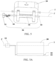
FIG. 5 is a diagram of a connection relationship between a first bracket and a second driving portion according to an embodiment of this application; -
FIG. 5A is a diagram of another connection relationship between a first bracket and a second driving portion according to an embodiment of this application; -
FIG. 6 is a structural diagram of a first bracket according to an embodiment of this application; -
FIG. 7 is a diagram of a connection relationship between a second bracket and a third driving portion according to an embodiment of this application; -
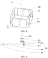
FIG. 8 is a structural diagram of a second bracket according to an embodiment of this application; -
FIG. 9 is an exploded view of a third driving portion according to an embodiment of this application; -
FIG. 10 is a structural diagram of a fixing base according to an embodiment of this application; -
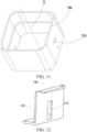
FIG. 11 is a structural diagram of a third bracket according to an embodiment of this application; -
FIG. 12 is a structural diagram of a first housing portion according to an embodiment of this application; -
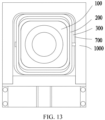
FIG. 13 is a structural top view of a camera module according to an embodiment of this application; -
FIG. 14 is a schematic diagram of adjusting a camera module by rotating around a first axis or a second axis according to an embodiment of this application; and -
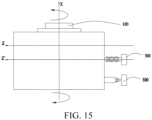
FIG. 15 is a schematic diagram of adjusting a camera module by rotating around a third axis according to an embodiment of this application. - Reference numerals:
- 100-camera, 110-camera body, 120-camera cover, 121-third connecting hole, 122-third hinge shaft, 123-mounting hole
- 200-first bracket, 210-first connecting hole, 220-arcuate hole, 230-second connecting hole
- 300-second bracket, 310-first accommodation groove, 320-second accommodation groove
- 400-first driving portion
- 500-second driving portion, 510-first driving motor, 520-first connecting shaft, 530-1-shaped bracket, 540-hinge
- 600-connecting block, 610-base, 620-first hinge shaft, 630-second hinge shaft
- 700-third bracket, 710-first strip-shaped avoidance hole
- 800-third driving portion, 810-second driving motor, 820-second connecting shaft, 830-gear mechanism, 831-first bevel gear, 832-second bevel gear, 833-third gear
- 900-rolling body
- 1000-fixing base, 1100-first housing portion, 1110-second strip-shaped avoidance hole, 1120-supporting platform, 1130-protective cover, 1140-third connecting shaft, 1200-second housing portion
- Y-first axis, Z-second axis, X-third axis, Z'-fourth axis
- To make the objectives, technical solutions, and advantages of the present invention clearer, the following describes the technical solutions of the present invention clearly and thoroughly with reference to specific embodiments of the present invention and the corresponding drawings. Evidently, the described embodiments are merely a part of but not all of the embodiments of the present invention. All other embodiments derived by a person of ordinary skill in the art based on the embodiments of the present invention without making any creative effort fall within the protection scope of the present invention.
- With reference to drawings, the following describes in detail the technical solution disclosed in each embodiment of this application.
- In some embodiments, a camera module shown in
FIG. 1 includes acamera 100, afirst bracket 200, asecond bracket 300, afirst driving portion 400, and asecond driving portion 500. - As shown in
FIG. 2 ,FIG. 5 , andFIG. 14 , thecamera 100 is disposed on thefirst bracket 200. Thefirst driving portion 400 is located on thesecond bracket 300 and connected to thecamera 100. Thesecond driving portion 500 is connected to thefirst bracket 200. Thefirst bracket 200 is rotatably connected to thesecond bracket 300. - As shown in
FIG. 6 andFIG. 8 , in a further assembling solution, both thefirst bracket 200 and thesecond bracket 300 may be of a cover-like and shell-like structure. Thesecond bracket 300 sheathes thefirst bracket 200, thefirst bracket 200 sheathes thecamera 100, and a clearance is maintained between the second bracket and the first bracket, and between the first bracket and the camera to ensure smooth rotation. - As shown in
FIG. 1 andFIG. 2 , in a process of shooting an image by using the camera module, thecamera 100 may be driven by thefirst driving portion 400 so that thecamera 100 rotates around a first axis Y relative to thefirst bracket 200. By rotating around the first axis Y, thecamera 100 implements image stabilization. - As shown in
FIG. 1 andFIG. 5 , in the process of shooting an image by using the camera module, thesecond driving portion 500 may be actuated so that thefirst bracket 200 and thecamera 100 as a whole are driven by thesecond driving portion 500. In this way, thefirst bracket 200 and thecamera 100 rotate around a second axis Z relative to thesecond bracket 300. By rotating around the second axis Z, thecamera 100 implements image stabilization. - The first axis Y and the second axis Z are non-coplanar straight lines or intersecting straight lines. In this way, the
camera 100 implements the image stabilization function by adjusting the rotation degree of freedom in two directions. During shooting, thecamera 100 rotates around the first axis Y or the second axis Z to stabilize images during the shooting and ensure quality of final images. As an optional solution, the first axis Y is perpendicular to the second axis Z so that it is easier to control the rotation of thecamera 100 to implement image stabilization. - More specifically, as shown in
FIG. 2 andFIG. 4 , thecamera 100 is used as an imaging component of the camera module. A main core component of the camera is acamera body 110. Thecamera body 110 is sheathed in acamera cover 120 so that thecamera cover 120 serves a shielding and protective function for thecamera body 110. - In addition, it is hereby pointed out that both the
first driving portion 400 and thesecond driving portion 500 may be of a motor structure. During actual assembling, a motor shaft of thefirst driving portion 400 may be connected to thecamera 100 along the first axis Y by means of shaft bossing, and a motor shaft of thesecond driving portion 500 may be connected to thefirst bracket 200 along the second axis Z by means of shaft bossing. - Further, as shown in
FIG. 2 ,FIG. 7 , andFIG. 8 , thesecond bracket 300 may include afirst accommodation groove 310. Thefirst driving portion 400 is located in thefirst accommodation groove 310 and connected to thecamera 100. Specifically, thefirst accommodation groove 310 may be opened along the first axis Y Thefirst driving portion 400 is accommodated in thefirst accommodation groove 310 along the first axis Y through the opening. - When the
camera 100 performs image stabilization by rotating around the first axis Y, thefirst accommodation groove 310 constrains the degree of freedom of thefirst driving portion 400 to prevent thefirst driving portion 400 from rotating around the first axis Y, from moving in a plane perpendicular to the first axis Y, and from incurring other circumstances. In this way, thefirst driving portion 400 in a stationary state drives thecamera 100 to rotate around the first axis Y - When the
camera 100 performs image stabilization by rotating around the second axis Z, thesecond driving portion 500 drives thefirst bracket 200 to rotate together with thecamera 100. At this time, thefirst accommodation groove 310 allows thefirst driving portion 400 to rotate around the second axis Z along with thefirst bracket 200, and thefirst driving portion 400 moves into thefirst accommodation groove 310 or moves out of thefirst accommodation groove 310 through the opening of thefirst accommodation groove 310. - To sum up, the
first accommodation groove 310 is opened along the first axis Y, and thefirst driving portion 400 is accommodated in thefirst accommodation groove 310. Under such design, thefirst driving portion 400 may serve as a driver to drive, in a stationary state, thecamera 100 to rotate around the first axis Y; and thefirst driving portion 400 may serve as a follower to, in a moving state, rotate around the second axis Z along with thecamera 100. In this way, the driving manner of thefirst driving portion 400 and thesecond driving portion 500 to drive thecamera 100 is more reasonable and effective, and makes the structure more compact. - It is hereby noted that, as an alternative, in order to implement the
first driving portion 400 and the above functions, thefirst driving portion 400 may be hinged on thesecond bracket 300, and a hinge shaft between the first driving portion and the second bracket is in the same direction as the second axis Z. In this way, the following effect is achieved: thefirst driving portion 400 is stationary when serving as a driver and is moving when serving as a follower. As another alternative, thefirst accommodation groove 310 may be replaced by two barrier strips spaced apart along the second axis Z. Thefirst driving portion 400 is disposed between the two barrier strips, thereby also achieving the above effect. - In some embodiments, as shown in
FIG. 2, FIG. 3 , andFIG. 6 , thecamera 100 may be rotatably in fit with thefirst bracket 200 through a connectingblock 600. The connectingblock 600 includes abase 610 and afirst hinge shaft 620. Thebase 610 is mounted on thecamera 100. Thefirst hinge shaft 620 is disposed on thebase 610. Thefirst bracket 200 is provided with a first connectinghole 210. Thefirst hinge shaft 620 is rotatably in fit with the first connectinghole 210, and connected to thefirst driving portion 400 by passing through the first connectinghole 210. In this way, thefirst driving portion 400 drives, through thefirst hinge shaft 620, thecamera 100 to rotate around the first axis Y, and the driving manner is more reasonable. - Further, as shown in
FIG. 3 andFIG. 6 , thefirst bracket 200 may be provided with anarcuate hole 220. The connectingblock 600 may further include asecond hinge shaft 630. Thesecond hinge shaft 630 is fixed onto thebase 610. Thesecond hinge shaft 630 is slidably in fit with thearcuate hole 220. Thesecond hinge shaft 630 is in limiting fit with two ends of thearcuate hole 220. With the position limited by thearcuate hole 220, the stroke of thesecond hinge shaft 630 is controlled. Further, an angle by which thecamera 100 rotates around the first axis Y is controlled by the connectingblock 600, so as to avoid excessive rotation. - More specifically, the
arcuate hole 220 is an arc segment formed by gyrating around the first axis Y A circle center of the first connectinghole 210 is located on the first axis Y In this way, thearcuate hole 220 may fit with the first connectinghole 210 to constrain the motion of the connectingblock 600. Therefore, a trajectory of thecamera 100 rotating around the first axis Y is more circular, the gyration of thecamera 100 is controlled more effectively, and the precision of rotation control is improved. - In addition, it is hereby pointed out that, as an alternative, the
arcuate hole 220 may be replaced by two symmetrically arranged limiting blocks located on the inner wall of thefirst bracket 200. Thesecond hinge shaft 630 is located between the two limiting blocks. The position limiting performed by the two limiting blocks on thesecond hinge shaft 630 can also control the angle by which thecamera 100 rotates around the first axis Y - In a more specific implementation solution, as shown in
FIG. 2 ,FIG. 4 , andFIG. 6 , thefirst bracket 200 is further provided with a second connectinghole 230. The second connectinghole 230 is coaxial with the first connectinghole 210. Thecamera 100 is provided with a third connectinghole 121. Thecamera 100 includes athird hinge shaft 122. Thethird hinge shaft 122 and thefirst hinge shaft 620 are located on two opposite sides of thecamera 100 respectively. Thethird hinge shaft 122 passes through the second connectinghole 230 and the third connectinghole 121, and is coaxial with thefirst hinge shaft 620. Thefirst bracket 200 is rotatably in fit with thecamera 100 through thethird hinge shaft 122. - In this way, the
third hinge shaft 122 and thefirst hinge shaft 620 is equivalent to a combined shaft that runs through thecamera 100 and that is disposed along the first axis Y The combined shaft is integrated with thecamera 100 to form a whole. In this way, thecamera 100 hangs on thefirst bracket 200 and is rotatably in fit with the second connectinghole 230 through thethird hinge shaft 122, and is rotatably in fit with the first connectinghole 210 through thefirst hinge shaft 620. In this way, thecamera 100 can rotate more smoothly around the first axis Y relative to thefirst bracket 200, and thecamera 100 is supported more uniformly. - More preferably, the
third hinge shaft 122 is detachably connected to thecamera 100, and is plugged and fixed onto thecamera 100 by passing through the second connectinghole 230 and the third connectinghole 121, so as to facilitate disassembly and assembly of thecamera 100 on thefirst bracket 200. In addition, as an optional solution of this application, thethird hinge shaft 122 may be formed on thecamera 100 in one piece. - The first connecting
hole 210 and the second connectinghole 230 are round holes in this application. As an alternative, the first connecting hole and the second connecting hole may be U-shaped holes. Open ends of the U-shaped holes are located at the top of thefirst bracket 200. During assembling, thethird hinge shaft 122 and thefirst hinge shaft 620 may be placed into the U-shaped holes through the open ends of the corresponding U-shaped holes, so that thecamera 100 is positioned in thefirst bracket 200. - Furthermore, as shown in
FIG. 4 , thecamera 100 may be provided with a mountinghole 123. Thebase 610 is fixed in the mountinghole 123 so that the connectingblock 600 is fixed to thecamera 100 more firmly. As an alternative, the mountinghole 123 may be replaced by two barrier strips or blocks spaced apart on thecamera 100 along the second axis Z, and thebase 610 is fixed between the two barrier strips or blocks spaced apart, thereby also enhancing the effect of fixing between the connectingblock 600 and thecamera 100. - In a more specific implementation solution, as shown in
FIG. 4 , the mountinghole 123 and the third connectinghole 121 are disposed opposite to each other in thecamera cover 120. Thethird hinge shaft 122 passes through the third connectinghole 121, and is fixed onto thecamera body 110. The base 610 passes through the mountinghole 123, and is also fixed onto thecamera body 110. - In some embodiments, as shown in
FIG. 5 , thesecond driving portion 500 includes afirst driving motor 510, a first connectingshaft 520, and an I-shapedbracket 530. Thefirst driving motor 510 is connected to the first connectingshaft 520. The I-shapedbracket 530 is fixed onto the first connectingshaft 520, and is connected to the bottom of thefirst bracket 200. For example, the I-shapedbracket 530 is fixedly disposed at the bottom of thefirst bracket 200 by bonding, welding, and the like. Alternatively, the I-shapedbracket 530 is fixed to the first connectingshaft 520, and closely fits with thefirst bracket 200. In this way, by actuating thesecond driving portion 500, a torque output by thesecond driving portion 500 is transmitted to the I-shapedbracket 530 through the first connectingshaft 520. Anchor plates on two wings of the I-shapedbracket 530 enable the I-shapedbracket 530 to output a torque to thefirst bracket 200, thereby driving thefirst bracket 200 to rotate around the second axis Z. - It is hereby pointed out that the rotation shaft of the
first driving motor 510 is a fourth axis Z'. Therefore, the fourth axis Z' needs to remain stationary along with thefirst driving motor 510. Other components of thesecond driving portion 500 such as the first connectingshaft 520 and the I-shapedbracket 530 will rotate around the second axis Z along with thefirst bracket 200. Therefore, thefirst driving motor 510 is connected by transmission to the first connectingshaft 520. The specific form of the driving connection may be: as shown inFIG. 5A , the fourth axis Z' is coaxial with the second axis Z, and an adapter disc is disposed at an output end of thefirst driving motor 510. At a circle center of the adapter disc, the adapter disc is connected to the output shaft of thefirst driving motor 510. At a position near the edge on the adapter disc, the adapter disc is connected to the first connectingshaft 520. In this way, thefirst driving motor 510 can transmit the torque to the first connectingshaft 520 through the adapter disc, and make the first connectingshaft 520 rotate around the second axis Z along with thefirst bracket 200. Alternatively, the adapter disc may be replaced by an adapter shaft. Two ends of the adapter shaft are connected to the output shaft of thefirst driving motor 510 and the first connectingshaft 520 respectively, thereby also making the first connectingshaft 520 rotate around the second axis Z. In this case, a gyroradius of the first connectingshaft 520 is a length dimension of the adapter shaft. - In some embodiments, as shown in
FIG. 1 ,FIG. 9 , andFIG. 11 , the camera module may further include athird bracket 700 and athird driving portion 800. Thesecond bracket 300 is disposed on thethird bracket 700. Thethird driving portion 800 is connected to thesecond bracket 300. Thethird driving portion 800 drives thesecond bracket 300 to rotate around the third axis X relative to thethird bracket 700. Thecamera 100 may rotate around the third axis X along with thesecond bracket 300. Every two of the first axis Y, the second axis Z, or the third axis X are non-coplanar straight lines or intersecting straight lines. In this way, as shown inFIG. 14 andFIG. 15 , thecamera 100 can implement image stabilization by adjusting the rotation degree of freedom in the three different directions. The image stabilization is more effective, and the shooting quality of images captured by a camera device according to this application is higher. - Furthermore, as an optional layout solution, the third axis X is coaxial with the optical axis of the
camera 100, and every two of the first axis Y, the second axis Z, or the third axis X are perpendicular to each other, so that the image stabilization manner of thecamera 100 is more reasonable. - More specifically, the
third driving portion 800 may be a motor. An output shaft of the motor is connected to thesecond bracket 300 by means of shaft bossing, so as to enable thesecond bracket 300 to rotate around the third axis X. Alternatively, thethird driving portion 800 may be a plurality of rollers powered by a motor mounted in thethird bracket 700. The periphery of the rollers closely fits with the outer periphery of thesecond bracket 300. The rotation of the rollers drives thesecond bracket 300 to rotate around the third axis X. - In a further implementation solution, as shown in
FIG. 1 andFIG. 7 , at least two rollingbodies 900 may be disposed between thethird bracket 700 and thesecond bracket 300. Thesecond bracket 300 is rotatably connected to thethird bracket 700 through the at least two rollingbodies 900. In this way, the rollingbodies 900 serve as a rolling medium between the second bracket and the third bracket, thereby making thesecond bracket 300 rotate more smoothly around the third axis X relative to thethird bracket 700, and alleviating abrasion. More specifically, the rollingbodies 900 may be designed as balls and rollers, or may be bearings. - Further, the
second bracket 300 or thethird bracket 700 is provided with at least twosecond accommodation grooves 320. Each of the rollingbodies 900 is disposed in one of thesecond accommodation grooves 320. - More specifically, both the
third bracket 700 and thesecond bracket 300 are of a box structure, and four angular corners of the box are filleted. Thesecond accommodation groove 320 is disposed on the fillet of thethird bracket 700 or thesecond bracket 300. There are a total of four rollingbodies 900 that are arranged annularly around the third axis X. One rolling body is disposed on eachsecond accommodation groove 320. This structure ensures that the space between the camera modules is more compact in a case of fitting with each other by rolling. - In a further implementation solution, as shown in
FIG. 10 andFIG. 13 , the camera module further includes afixing base 1000. Thethird bracket 700 is mounted on thefixing base 1000. - As shown in
FIG. 5 andFIG. 14 , thefirst driving motor 510 is connected by transmission to the first connectingshaft 520 by ahinge 540. A hinge shaft of thehinge 540 is parallel to the optical axis direction of thecamera 100, that is, the third axis X. Thefirst driving motor 510 is fixed onto the fixingbase 1000, and is located outside thethird bracket 700. - As shown in
FIG. 11 andFIG. 14 , thethird bracket 700 is provided with a first strip-shapedavoidance hole 710. Thehinge 540 passes through the first strip-shapedavoidance hole 710, and is connected to the first connectingshaft 520 located in thethird bracket 700. - As shown in
FIG. 5 andFIG. 6 , thefirst driving motor 510 together with the first connectingshaft 520 may be disposed at the bottom of thefirst bracket 200. The second axis Z and the fourth axis Z' are parallel but not coaxial. In this way, when thefirst driving motor 510 is actuated, by virtue of the characteristic that the hinge shaft of thehinge 540 is parallel to the third axis X, thehinge 540 is caused to be rigid in a direction parallel to the third axis X, and in turn, the drivingmotor 510 can transmit a torque to the first connectingshaft 520 through thehinge 540. At the same time, thehinge 540 is flexible in a direction perpendicular to the second axis Z. In this way, in a case that the drivingmotor 510 keeps stationary, the driving motor drives the first connectingshaft 520 to rotate around the second axis Z, and in turn, causes thefirst bracket 200 to rotate around the second axis Z. In this case, thehinge 540 may deform along with the rotation of thefirst bracket 200, so as to change the relative position between the drivingmotor 510 and the first connectingshaft 520. - In addition, it is hereby pointed out that, by virtue of the flexibility of the
hinge 540, when thethird driving portion 800 is actuated, thesecond bracket 300 rotates around the optical axis of thecamera 100, that is, the third axis X. In this case, thehinge 540 may deform along with the rotation of thesecond bracket 300, so as to change the relative position between the drivingmotor 510 and the first connectingshaft 520. It is hereby noted that the first strip-shapedavoidance hole 710 is made for the purpose of reserving sufficient space for deformation of thehinge 540, and enabling the hinge to deform sufficiently. - In a further implementation solution, as shown in
FIG. 10 andFIG. 13 , the fixingbase 1000 is a housing structure. The fixingbase 1000 includes afirst housing portion 1100 and asecond housing portion 1200. Thefirst housing portion 1100 is docked to thesecond housing portion 1200 to form an accommodation cavity. Thethird bracket 700 is located in the accommodation cavity. Thesecond bracket 300 is located in thethird bracket 700. Thefirst bracket 200 is located in thesecond bracket 300. Thecamera 100 is located in thefirst bracket 200. In this way, the fixingbase 1000 can shield and protect internal parts and serve a dustproof and waterproof function. - In addition, as shown in
FIG. 10 andFIG. 12 , thefirst housing portion 1100 may be provided with a second strip-shapedavoidance hole 1110. A supportingplatform 1120 may be disposed on an outer side of thefirst housing portion 1100. The supportingplatform 1120 is covered with aprotective cover 1130. Thefirst driving motor 510 is located inside theprotective cover 1130 to shield and protect thefirst driving motor 510. Thehinge 540 passes through the second strip-shapedavoidance hole 1110 and the first strip-shapedavoidance hole 710 sequentially to get connected to the first connectingshaft 520. In this way, enough space is reserved in both the second strip-shapedavoidance hole 1110 and the first strip-shapedavoidance hole 710 to enable thehinge 540 to deform sufficiently. - In some embodiments, as shown in
FIG. 9 , thethird driving portion 800 includes asecond driving motor 810, a second connectingshaft 820, and agear mechanism 830. Thegear mechanism 830 includes afirst bevel gear 831, asecond bevel gear 832, and athird gear 833. Thefirst bevel gear 831 is disposed on the second connectingshaft 820. A third connectingshaft 1140 coaxial with the third axis X is rotatably disposed on thefixing base 1000. The second connectingshaft 820 is perpendicular to the third connectingshaft 1140. - The
second bevel gear 832 and thethird gear 833 are fixed to each other, and are both rotatably connected to the third connectingshaft 1140. For example, the third connectingshaft 1140 may be a rotating sleeve in which a bearing is disposed. Thefirst bevel gear 831 meshes with thesecond bevel gear 832. An inner ring gear is disposed on thethird bracket 700. Thethird gear 833 meshes with the inner ring gear. - The
second driving motor 810 drives, through the second connectingshaft 820, thegear mechanism 830 to rotate, and in turn, drives, through thethird gear 833, thethird bracket 700 to bring thecamera 100 to rotate around the optical axis of the camera. - In this way, the design of the bevel gear pair implements reversing transmission, so as to make better use of the internal space of the camera module. In addition, it is hereby pointed out that, as an alternative, the
gear mechanism 830 may be replaced by a chain transmission mechanism, a belt transmission mechanism, a worm gear mechanism, or the like. - This application further discloses an electronic device. The electronic device includes the camera module according to any one of the above embodiments of this application. The electronic device disclosed herein may be a mobile phone, a tablet computer, an e-book reader, a wearable device (such as smart glasses and smart watches), a game console, or the like, and may be other types of devices. The specific type of the electronic device is not limited herein.
- The above embodiments of this application are described by focusing on the differences between the embodiments. Different technical features optimized based on various embodiments may be combined to form an optimized embodiment as long as the features do not conflict with each other. For brevity, details of the optimized embodiment are omitted herein.
- What is described above is merely optional embodiments of this application, but not intended to limit this application. To a person skilled in the art, various modifications and variations may be made to this application. Any modifications, equivalent replacements, improvements, and the like made without departing from the spirit and principles of this application still fall within the protection scope of claims of this application.
Claims (15)
- A camera module, comprising a camera, a first bracket, a second bracket, a first driving portion, and a second driving portion, whereinthe camera is disposed on the first bracket, the first driving portion is located on the second bracket and connected to the camera, the second driving portion is connected to the first bracket, and the first bracket is rotatably connected to the second bracket; andthe first driving portion is able to drive the camera to rotate around a first axis relative to the first bracket; the second driving portion is able to drive the first bracket and the camera to rotate around a second axis relative to the second bracket; and the first axis and the second axis are non-coplanar straight lines or intersecting straight lines.
- The camera module according to claim 1, wherein the second bracket comprises a first accommodation groove; and the first driving portion is located in the first accommodation groove; and
the first driving portion is able to rotate around the second axis along with the first bracket, so as to move into the first accommodation groove or move out of the first accommodation groove through an opening of the first accommodation groove. - The camera module according to claim 1, wherein the camera is rotatably in fit with the first bracket through a connecting block, the connecting block comprises a base mounted on the camera and a first hinge shaft disposed on the base, and the first bracket is provided with a first connecting hole;the first hinge shaft is rotatably in fit with the first connecting hole, and connected to the first driving portion by passing through the first connecting hole; andthe first driving portion drives, through the first hinge shaft, the camera to rotate around the first axis.
- The camera module according to claim 3, wherein the first bracket is further provided with an arcuate hole, the connecting block further comprises a second hinge shaft fixed onto the base, the second hinge shaft is slidably in fit with the arcuate hole, and the second hinge shaft is in limiting fit with two ends of the arcuate hole.
- The camera module according to claim 3, wherein the first bracket is further provided with a second connecting hole, the second connecting hole is disposed coaxial with the first connecting hole, and the camera is provided with a third connecting hole;the camera further comprises a third hinge shaft, the third hinge shaft is coaxial with the first hinge shaft, and the third hinge shaft and the first hinge shaft are located on two opposite sides of the camera respectively; andthe third hinge shaft passes through the second connecting hole and the third connecting hole, and the first bracket is rotatably in fit with the camera through the third hinge shaft.
- The camera module according to claim 3, wherein the camera is provided with a mounting hole, and the base is fixed in the mounting hole.
- The camera module according to claim 1, wherein the second driving portion comprises a first driving motor, a first connecting shaft, and an I-shaped bracket; the first driving motor is connected to the first connecting shaft; and the I-shaped bracket is fixed onto the first connecting shaft and connected to a bottom of the first bracket.
- The camera module according to claim 7, wherein the camera module further comprises a third bracket and a third driving portion; the second bracket is disposed on the third bracket and connected to the third driving portion; the third driving portion drives the second bracket to rotate around a third axis relative to the third bracket; the camera is able to rotate around the third axis along with the second bracket; the third axis is coaxial with an optical axis of the camera; and every two of the first axis, the second axis, or the third axis are non-coplanar straight lines or intersecting straight lines.
- The camera module according to claim 8, wherein at least two rolling bodies are disposed between the third bracket and the second bracket; and
the second bracket is rotatably connected to the third bracket through the at least two rolling bodies. - The camera module according to claim 9, wherein the second bracket or the third bracket is provided with at least two second accommodation grooves, and each of the rolling bodies is disposed in one of the second accommodation grooves.
- The camera module according to claim 8, wherein the camera module further comprises a fixing base; the third bracket is mounted on the fixing base; the first driving motor is connected by transmission to the first connecting shaft through a hinge; a hinge axis of the hinge is parallel to an optical axis direction of the camera; the first driving motor is fixed onto the fixing base, and is located outside the third bracket; the third bracket is provided with a first strip-shaped avoidance hole; the hinge passes through the first strip-shaped avoidance hole, and is connected to the first connecting shaft located in the third bracket; and the hinge deforms when the second bracket rotates around the optical axis of the camera, or the hinge deforms when the first bracket rotates around the second axis.
- The camera module according to claim 11, wherein the fixing base is a housing structure, the fixing base comprises a first housing portion and a second housing portion, the first housing portion is docked to the second housing portion to form an accommodation cavity, the third bracket is located in the accommodation cavity, the second bracket is located in the third bracket, and the first bracket is located in the second bracket.
- The camera module according to claim 12, wherein the first housing portion is provided with a second strip-shaped avoidance hole, a supporting platform is disposed on an outer side of the first housing portion, the supporting platform is covered with a protective cover, the first driving motor is located inside the protective cover, and the hinge passes through the second strip-shaped avoidance hole and the first strip-shaped avoidance hole sequentially to get connected to the first connecting shaft.
- The camera module according to claim 8, wherein the third driving portion comprises a second driving motor, a second connecting shaft, and a gear mechanism; the gear mechanism comprises a first bevel gear, a second bevel gear, and a third gear; the first bevel gear is disposed on the second connecting shaft; a third connecting shaft coaxial with the third axis is rotatably disposed on the fixing base; and the second connecting shaft is perpendicular to the third connecting shaft;the second bevel gear and the third gear are fixed to each other, and are both rotatably connected to the third connecting shaft, the first bevel gear meshes with the second bevel gear, an inner ring gear is disposed on the third bracket, and the third gear meshes with the inner ring gear; andthe second driving motor drives, through the second connecting shaft, the gear mechanism to rotate, and in turn, drives, through the third gear, the third bracket to bring the camera to rotate around the optical axis of the camera.
- An electronic device, comprising the camera module according to any one of claims 1 to 14.
Applications Claiming Priority (2)
| Application Number | Priority Date | Filing Date | Title |
|---|---|---|---|
| CN202011497271.4A CN112492218B (en) | 2020-12-17 | 2020-12-17 | Camera module and electronic equipment |
| PCT/CN2021/137353 WO2022127724A1 (en) | 2020-12-17 | 2021-12-13 | Camera module and electronic device |
Publications (3)
| Publication Number | Publication Date |
|---|---|
| EP4236297A1 true EP4236297A1 (en) | 2023-08-30 |
| EP4236297A4 EP4236297A4 (en) | 2024-04-24 |
| EP4236297B1 EP4236297B1 (en) | 2025-08-20 |
Family
ID=74917297
Family Applications (1)
| Application Number | Title | Priority Date | Filing Date |
|---|---|---|---|
| EP21905653.8A Active EP4236297B1 (en) | 2020-12-17 | 2021-12-13 | Camera module and electronic device |
Country Status (6)
| Country | Link |
|---|---|
| US (1) | US12267571B2 (en) |
| EP (1) | EP4236297B1 (en) |
| JP (1) | JP7583938B2 (en) |
| CN (1) | CN112492218B (en) |
| ES (1) | ES3041773T3 (en) |
| WO (1) | WO2022127724A1 (en) |
Families Citing this family (6)
| Publication number | Priority date | Publication date | Assignee | Title |
|---|---|---|---|---|
| CN112492218B (en) * | 2020-12-17 | 2022-04-08 | 维沃移动通信有限公司 | Camera module and electronic equipment |
| CN113163040B (en) * | 2021-05-20 | 2023-03-14 | 维沃移动通信有限公司 | Electronic device |
| CN116156299B (en) * | 2021-11-17 | 2025-01-24 | 维沃移动通信有限公司 | Camera modules and electronic equipment |
| CN114531006B (en) * | 2022-04-01 | 2023-09-12 | 浙江舜宇智领技术有限公司 | Linear rotating motor and vehicle-mounted anti-shake imaging device |
| CN115174795B (en) * | 2022-08-25 | 2024-10-15 | 杭州海康威视数字技术股份有限公司 | Camera |
| CN119233060B (en) * | 2024-11-26 | 2025-02-25 | 杭州海康威视数字技术股份有限公司 | Swaying camera |
Family Cites Families (25)
| Publication number | Priority date | Publication date | Assignee | Title |
|---|---|---|---|---|
| JP2000010139A (en) * | 1998-06-18 | 2000-01-14 | Asahi Optical Co Ltd | Image blur correction camera and camera image blur correction method |
| JP2005326807A (en) * | 2004-04-12 | 2005-11-24 | Konica Minolta Photo Imaging Inc | Camera with built-in lens barrel |
| JP5011793B2 (en) * | 2006-04-05 | 2012-08-29 | 株式会社ニコン | Lens barrel and imaging device |
| JP2008191615A (en) * | 2007-02-08 | 2008-08-21 | Casio Comput Co Ltd | Image stabilizer |
| KR101022548B1 (en) * | 2009-03-31 | 2011-03-16 | 정성호 | Camera module 3-axis rotating bracket assembly of surveillance camera device |
| JP2013140285A (en) | 2012-01-05 | 2013-07-18 | Sony Corp | Image shake correction device and imaging device |
| JP6320044B2 (en) * | 2014-01-08 | 2018-05-09 | キヤノン株式会社 | Image blur correction device, lens device, and imaging device |
| TWI588592B (en) | 2015-06-16 | 2017-06-21 | 台灣東電化股份有限公司 | Thin-plate-typed rotating module |
| US10534154B2 (en) * | 2017-06-16 | 2020-01-14 | Apple Inc. | Interlock arrangement for attaching a lens barrel to a lens carrier |
| CN108674366B (en) * | 2018-05-11 | 2021-11-16 | 深圳市通利达电子有限公司 | Face recognition equipment that duration is strong |
| EP3817357B1 (en) * | 2018-07-09 | 2023-05-10 | Guangdong Oppo Mobile Telecommunications Corp., Ltd. | Camera module, assembly, electronic device, mobile terminal, and photography method |
| CN108696687A (en) * | 2018-07-11 | 2018-10-23 | Oppo广东移动通信有限公司 | Camera assembly of electronic device and electronic device with same |
| KR102626510B1 (en) * | 2018-10-05 | 2024-01-19 | 엘지이노텍 주식회사 | Camera Actuator and Camera module including the same |
| CN109379529B (en) * | 2018-12-20 | 2024-09-17 | 歌尔科技有限公司 | Electronic equipment, camera and camera shielding mechanism |
| JP7344679B2 (en) | 2019-06-14 | 2023-09-14 | ニデックインスツルメンツ株式会社 | Optical unit with shake correction function |
| CN110677567B (en) | 2019-09-30 | 2020-11-13 | 维沃移动通信有限公司 | Camera module and electronic equipment |
| CN110572556B (en) | 2019-09-30 | 2021-02-02 | 维沃移动通信有限公司 | Camera module and electronic equipment |
| CN110673656B (en) * | 2019-09-30 | 2024-03-26 | 维沃移动通信有限公司 | Camera module, electronic equipment and control method of camera module |
| KR102843872B1 (en) * | 2020-01-10 | 2025-08-08 | 삼성전자주식회사 | Camera module and electronic device including the same |
| CN211266959U (en) * | 2020-02-13 | 2020-08-14 | 南昌欧菲光电技术有限公司 | Camera module, camera device and electronic equipment |
| CN111212215B (en) * | 2020-04-20 | 2020-08-14 | 瑞声通讯科技(常州)有限公司 | Camera assembly |
| CN113669563B (en) * | 2020-04-30 | 2025-02-14 | 新思考电机有限公司 | Two-axis tilt device, camera device and electronic equipment |
| CN111917966B (en) * | 2020-08-26 | 2025-01-28 | 河南皓泽电子股份有限公司昆山分公司 | Camera module and electronic equipment |
| CN112492218B (en) * | 2020-12-17 | 2022-04-08 | 维沃移动通信有限公司 | Camera module and electronic equipment |
| CN112822354B (en) * | 2020-12-28 | 2023-01-31 | 维沃移动通信有限公司 | Camera module and electronic equipment |
-
2020
- 2020-12-17 CN CN202011497271.4A patent/CN112492218B/en active Active
-
2021
- 2021-12-13 WO PCT/CN2021/137353 patent/WO2022127724A1/en not_active Ceased
- 2021-12-13 ES ES21905653T patent/ES3041773T3/en active Active
- 2021-12-13 JP JP2023532758A patent/JP7583938B2/en active Active
- 2021-12-13 EP EP21905653.8A patent/EP4236297B1/en active Active
-
2023
- 2023-05-30 US US18/203,358 patent/US12267571B2/en active Active
Also Published As
| Publication number | Publication date |
|---|---|
| CN112492218B (en) | 2022-04-08 |
| EP4236297B1 (en) | 2025-08-20 |
| ES3041773T3 (en) | 2025-11-14 |
| EP4236297A4 (en) | 2024-04-24 |
| CN112492218A (en) | 2021-03-12 |
| US20230308734A1 (en) | 2023-09-28 |
| WO2022127724A1 (en) | 2022-06-23 |
| US12267571B2 (en) | 2025-04-01 |
| JP2023552185A (en) | 2023-12-14 |
| JP7583938B2 (en) | 2024-11-14 |
Similar Documents
| Publication | Publication Date | Title |
|---|---|---|
| US12267571B2 (en) | Camera module and electronic device | |
| CN110572556B (en) | Camera module and electronic equipment | |
| US20200401021A1 (en) | Camera System and Mobile Terminal Using Same | |
| CN112532840A (en) | Electronic device | |
| KR100919987B1 (en) | Small digital zoom camera and mobile phone equipped with it | |
| US7342606B2 (en) | Zoom lens system for camera | |
| CN210518443U (en) | Electronic device | |
| US12326762B2 (en) | Flip function assembly and electronic device | |
| WO2022143368A1 (en) | Camera module and electronic device | |
| WO2021114280A1 (en) | Follower and gimbal assembly | |
| CN112073621A (en) | Camera Modules and Electronic Equipment | |
| CN113163040B (en) | Electronic device | |
| CN213305531U (en) | Electronic equipment | |
| EP3703348B1 (en) | Electronic device with rotating member | |
| WO2022127653A1 (en) | Photographing module and electronic device | |
| EP4422191A1 (en) | Camera assembly and electronic device | |
| EP4265953B1 (en) | Electronic device, and photographic apparatus thereof | |
| JP2005202316A (en) | Hollow motor integrated lens barrel | |
| CN111491091B (en) | Shooting terminal with image stability enhancement function | |
| US8896933B2 (en) | Lens barrel | |
| CN110115552B (en) | Vision unit adjustment device for cleaning robots | |
| CN222545564U (en) | Lens adjustment structure and imaging device | |
| CN209839566U (en) | Automatic rotating mechanism of cradle head | |
| CN112702493B (en) | Electronic device | |
| CN111385381B (en) | Electronic equipment |
Legal Events
| Date | Code | Title | Description |
|---|---|---|---|
| STAA | Information on the status of an ep patent application or granted ep patent |
Free format text: STATUS: THE INTERNATIONAL PUBLICATION HAS BEEN MADE |
|
| PUAI | Public reference made under article 153(3) epc to a published international application that has entered the european phase |
Free format text: ORIGINAL CODE: 0009012 |
|
| STAA | Information on the status of an ep patent application or granted ep patent |
Free format text: STATUS: REQUEST FOR EXAMINATION WAS MADE |
|
| 17P | Request for examination filed |
Effective date: 20230526 |
|
| AK | Designated contracting states |
Kind code of ref document: A1 Designated state(s): AL AT BE BG CH CY CZ DE DK EE ES FI FR GB GR HR HU IE IS IT LI LT LU LV MC MK MT NL NO PL PT RO RS SE SI SK SM TR |
|
| REG | Reference to a national code |
Free format text: PREVIOUS MAIN CLASS: H04N0005232000 Ipc: H04N0023550000 Ref country code: DE Ref legal event code: R079 Ref document number: 602021036906 Country of ref document: DE |
|
| DAV | Request for validation of the european patent (deleted) | ||
| DAX | Request for extension of the european patent (deleted) | ||
| A4 | Supplementary search report drawn up and despatched |
Effective date: 20240325 |
|
| RIC1 | Information provided on ipc code assigned before grant |
Ipc: H04N 23/68 20230101ALI20240319BHEP Ipc: H04N 23/57 20230101ALI20240319BHEP Ipc: H04N 23/55 20230101AFI20240319BHEP |
|
| GRAP | Despatch of communication of intention to grant a patent |
Free format text: ORIGINAL CODE: EPIDOSNIGR1 |
|
| STAA | Information on the status of an ep patent application or granted ep patent |
Free format text: STATUS: GRANT OF PATENT IS INTENDED |
|
| GRAS | Grant fee paid |
Free format text: ORIGINAL CODE: EPIDOSNIGR3 |
|
| INTG | Intention to grant announced |
Effective date: 20250616 |
|
| GRAA | (expected) grant |
Free format text: ORIGINAL CODE: 0009210 |
|
| STAA | Information on the status of an ep patent application or granted ep patent |
Free format text: STATUS: THE PATENT HAS BEEN GRANTED |
|
| AK | Designated contracting states |
Kind code of ref document: B1 Designated state(s): AL AT BE BG CH CY CZ DE DK EE ES FI FR GB GR HR HU IE IS IT LI LT LU LV MC MK MT NL NO PL PT RO RS SE SI SK SM TR |
|
| REG | Reference to a national code |
Ref country code: GB Ref legal event code: FG4D |
|
| REG | Reference to a national code |
Ref country code: CH Ref legal event code: EP |
|
| REG | Reference to a national code |
Ref country code: IE Ref legal event code: FG4D |
|
| REG | Reference to a national code |
Ref country code: DE Ref legal event code: R096 Ref document number: 602021036906 Country of ref document: DE |
|
| REG | Reference to a national code |
Ref country code: NL Ref legal event code: FP |
|
| REG | Reference to a national code |
Ref country code: ES Ref legal event code: FG2A Ref document number: 3041773 Country of ref document: ES Kind code of ref document: T3 Effective date: 20251114 |
|
| PGFP | Annual fee paid to national office [announced via postgrant information from national office to epo] |
Ref country code: NL Payment date: 20251112 Year of fee payment: 5 |
|
| PG25 | Lapsed in a contracting state [announced via postgrant information from national office to epo] |
Ref country code: IS Free format text: LAPSE BECAUSE OF FAILURE TO SUBMIT A TRANSLATION OF THE DESCRIPTION OR TO PAY THE FEE WITHIN THE PRESCRIBED TIME-LIMIT Effective date: 20251220 |
|
| PGFP | Annual fee paid to national office [announced via postgrant information from national office to epo] |
Ref country code: DE Payment date: 20251028 Year of fee payment: 5 |
|
| PGFP | Annual fee paid to national office [announced via postgrant information from national office to epo] |
Ref country code: GB Payment date: 20251030 Year of fee payment: 5 |
|
| PG25 | Lapsed in a contracting state [announced via postgrant information from national office to epo] |
Ref country code: NO Free format text: LAPSE BECAUSE OF FAILURE TO SUBMIT A TRANSLATION OF THE DESCRIPTION OR TO PAY THE FEE WITHIN THE PRESCRIBED TIME-LIMIT Effective date: 20251120 |
|
| REG | Reference to a national code |
Ref country code: LT Ref legal event code: MG9D |
|
| PG25 | Lapsed in a contracting state [announced via postgrant information from national office to epo] |
Ref country code: PT Free format text: LAPSE BECAUSE OF FAILURE TO SUBMIT A TRANSLATION OF THE DESCRIPTION OR TO PAY THE FEE WITHIN THE PRESCRIBED TIME-LIMIT Effective date: 20251222 |
|
| PG25 | Lapsed in a contracting state [announced via postgrant information from national office to epo] |
Ref country code: FI Free format text: LAPSE BECAUSE OF FAILURE TO SUBMIT A TRANSLATION OF THE DESCRIPTION OR TO PAY THE FEE WITHIN THE PRESCRIBED TIME-LIMIT Effective date: 20250820 |
|
| PGFP | Annual fee paid to national office [announced via postgrant information from national office to epo] |
Ref country code: IT Payment date: 20251121 Year of fee payment: 5 |
|
| PG25 | Lapsed in a contracting state [announced via postgrant information from national office to epo] |
Ref country code: HR Free format text: LAPSE BECAUSE OF FAILURE TO SUBMIT A TRANSLATION OF THE DESCRIPTION OR TO PAY THE FEE WITHIN THE PRESCRIBED TIME-LIMIT Effective date: 20250820 |
|
| PGFP | Annual fee paid to national office [announced via postgrant information from national office to epo] |
Ref country code: FR Payment date: 20251110 Year of fee payment: 5 |
|
| PG25 | Lapsed in a contracting state [announced via postgrant information from national office to epo] |
Ref country code: GR Free format text: LAPSE BECAUSE OF FAILURE TO SUBMIT A TRANSLATION OF THE DESCRIPTION OR TO PAY THE FEE WITHIN THE PRESCRIBED TIME-LIMIT Effective date: 20251121 |
|
| PG25 | Lapsed in a contracting state [announced via postgrant information from national office to epo] |
Ref country code: SE Free format text: LAPSE BECAUSE OF FAILURE TO SUBMIT A TRANSLATION OF THE DESCRIPTION OR TO PAY THE FEE WITHIN THE PRESCRIBED TIME-LIMIT Effective date: 20250820 |
|
| PG25 | Lapsed in a contracting state [announced via postgrant information from national office to epo] |
Ref country code: LV Free format text: LAPSE BECAUSE OF FAILURE TO SUBMIT A TRANSLATION OF THE DESCRIPTION OR TO PAY THE FEE WITHIN THE PRESCRIBED TIME-LIMIT Effective date: 20250820 |
|
| PG25 | Lapsed in a contracting state [announced via postgrant information from national office to epo] |
Ref country code: PL Free format text: LAPSE BECAUSE OF FAILURE TO SUBMIT A TRANSLATION OF THE DESCRIPTION OR TO PAY THE FEE WITHIN THE PRESCRIBED TIME-LIMIT Effective date: 20250820 Ref country code: BG Free format text: LAPSE BECAUSE OF FAILURE TO SUBMIT A TRANSLATION OF THE DESCRIPTION OR TO PAY THE FEE WITHIN THE PRESCRIBED TIME-LIMIT Effective date: 20250820 |
|
| PG25 | Lapsed in a contracting state [announced via postgrant information from national office to epo] |
Ref country code: RS Free format text: LAPSE BECAUSE OF FAILURE TO SUBMIT A TRANSLATION OF THE DESCRIPTION OR TO PAY THE FEE WITHIN THE PRESCRIBED TIME-LIMIT Effective date: 20251120 |
|
| REG | Reference to a national code |
Ref country code: AT Ref legal event code: MK05 Ref document number: 1828668 Country of ref document: AT Kind code of ref document: T Effective date: 20250820 |
|
| PG25 | Lapsed in a contracting state [announced via postgrant information from national office to epo] |
Ref country code: RO Free format text: LAPSE BECAUSE OF FAILURE TO SUBMIT A TRANSLATION OF THE DESCRIPTION OR TO PAY THE FEE WITHIN THE PRESCRIBED TIME-LIMIT Effective date: 20250820 |
|
| PG25 | Lapsed in a contracting state [announced via postgrant information from national office to epo] |
Ref country code: SM Free format text: LAPSE BECAUSE OF FAILURE TO SUBMIT A TRANSLATION OF THE DESCRIPTION OR TO PAY THE FEE WITHIN THE PRESCRIBED TIME-LIMIT Effective date: 20250820 |
|
| PGFP | Annual fee paid to national office [announced via postgrant information from national office to epo] |
Ref country code: ES Payment date: 20260116 Year of fee payment: 5 |
|
| PG25 | Lapsed in a contracting state [announced via postgrant information from national office to epo] |
Ref country code: DK Free format text: LAPSE BECAUSE OF FAILURE TO SUBMIT A TRANSLATION OF THE DESCRIPTION OR TO PAY THE FEE WITHIN THE PRESCRIBED TIME-LIMIT Effective date: 20250820 |
|
| PG25 | Lapsed in a contracting state [announced via postgrant information from national office to epo] |
Ref country code: AT Free format text: LAPSE BECAUSE OF FAILURE TO SUBMIT A TRANSLATION OF THE DESCRIPTION OR TO PAY THE FEE WITHIN THE PRESCRIBED TIME-LIMIT Effective date: 20250820 |
|
| PG25 | Lapsed in a contracting state [announced via postgrant information from national office to epo] |
Ref country code: CZ Free format text: LAPSE BECAUSE OF FAILURE TO SUBMIT A TRANSLATION OF THE DESCRIPTION OR TO PAY THE FEE WITHIN THE PRESCRIBED TIME-LIMIT Effective date: 20250820 |
|
| PG25 | Lapsed in a contracting state [announced via postgrant information from national office to epo] |
Ref country code: EE Free format text: LAPSE BECAUSE OF FAILURE TO SUBMIT A TRANSLATION OF THE DESCRIPTION OR TO PAY THE FEE WITHIN THE PRESCRIBED TIME-LIMIT Effective date: 20250820 Ref country code: SK Free format text: LAPSE BECAUSE OF FAILURE TO SUBMIT A TRANSLATION OF THE DESCRIPTION OR TO PAY THE FEE WITHIN THE PRESCRIBED TIME-LIMIT Effective date: 20250820 |