EP4236173B1 - Zeitbereichszuordnung für wiederholungen - Google Patents
Zeitbereichszuordnung für wiederholungen Download PDFInfo
- Publication number
- EP4236173B1 EP4236173B1 EP23176911.8A EP23176911A EP4236173B1 EP 4236173 B1 EP4236173 B1 EP 4236173B1 EP 23176911 A EP23176911 A EP 23176911A EP 4236173 B1 EP4236173 B1 EP 4236173B1
- Authority
- EP
- European Patent Office
- Prior art keywords
- pair
- length
- value
- slot
- slot border
- Prior art date
- Legal status (The legal status is an assumption and is not a legal conclusion. Google has not performed a legal analysis and makes no representation as to the accuracy of the status listed.)
- Active
Links
Images


Classifications
-
- H—ELECTRICITY
- H04—ELECTRIC COMMUNICATION TECHNIQUE
- H04L—TRANSMISSION OF DIGITAL INFORMATION, e.g. TELEGRAPHIC COMMUNICATION
- H04L1/00—Arrangements for detecting or preventing errors in the information received
- H04L1/08—Arrangements for detecting or preventing errors in the information received by repeating transmission, e.g. Verdan system
-
- H—ELECTRICITY
- H04—ELECTRIC COMMUNICATION TECHNIQUE
- H04L—TRANSMISSION OF DIGITAL INFORMATION, e.g. TELEGRAPHIC COMMUNICATION
- H04L5/00—Arrangements affording multiple use of the transmission path
- H04L5/003—Arrangements for allocating sub-channels of the transmission path
- H04L5/0044—Allocation of payload; Allocation of data channels, e.g. PDSCH or PUSCH
-
- H—ELECTRICITY
- H04—ELECTRIC COMMUNICATION TECHNIQUE
- H04W—WIRELESS COMMUNICATION NETWORKS
- H04W72/00—Local resource management
- H04W72/04—Wireless resource allocation
- H04W72/044—Wireless resource allocation based on the type of the allocated resource
- H04W72/0446—Resources in time domain, e.g. slots or frames
Definitions
- the present disclosure relates generally to communications, and more particularly to communicating transport block repetitions in a radio access network and related network nodes.
- NR New Radio
- a slot is defined to be 14 symbols and a subframe is 1 ms.
- the length of a subframe is hence as in Long-Term Evolution (LTE), but depending on numerology, the number of slots per subframe varies.
- LTE Long-Term Evolution
- the numerologies 15 kHz and 30 kHz Sub-Carrier Spacing (SCS) is supported, while 60 kHz SCS is optional for User Equipment (UE).
- 15 kHz SCS equals the LTE numerology for normal cyclic prefix.
- NR supports two types of transmissions: Type A and Type B. Type A is usually referred to as slot-based, while Type B transmissions may be referred to as non-slot-based or mini-slot-based.
- Mini-slot transmissions can be dynamically scheduled and shall in Release 15 (Rel-15) obey:
- mini-slot transmission would not start in any symbol within a slot, but rather would follow the pattern of configured DL control search space (CORESET).
- CORESET configured DL control search space
- the location of configured DL control search space e.g., the union of the Control Channel Element (CCE) sets where Downlink Control Information (DCI) can be received in a given mini-slot
- DCI Downlink Control Information
- PDSCH Physical Downlink Shared Channel
- TTI Transmission Time Interval
- Type B transmissions are important for Ultra-Reliable Low-Latency Communication (URLLC) since it reduces latency; the transmissions can be scheduled and start sooner than for slot-based transmissions where scheduling and transmissions need to wait until the next slot.
- URLLC Ultra-Reliable Low-Latency Communication
- Repetition or aggregation is a feature supported by NR where a transport block (TB) transmission can be repeated/re-transmitted K times. TB repetitions can thus be viewed as non-HARQ-based retransmissions, i.e., all K TB re-transmissions/repetitions are performed using consecutive TTls without knowledge of whether any specific transmission in the set of K transmissions was correctly decoded or not.
- Repetition is a feature to improve the robustness when the latency requirements are so strict that no HARQ-based re-transmissions are possible without violating the latency requirement.
- a known method is disclosed in INTEL CORPORATION: "Remaining issues of UL transmission procedures", 3GPP DRAFT; R1-1802416.
- Figure 1 is an example block diagram illustrating scheduling of Physical Uplink Shared Channel (PUSCH) repetition near a slot border.
- the filled block 102 indicates an UL grant transmission on Physical Downlink Control Channel (PDCCH) on DL carrier, while the hatched blocks (e.g., 104) indicate three repetitions of 2-OFDM symbol long PUSCH transmissions.
- PDCCH Physical Downlink Control Channel
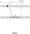
- Figure 3 is an example block diagram illustrating scheduling of PUSCH repetition near a slot border.
- the filled block 302 indicates an UL grant transmission on PDCCH on DL carrier, while the hatched blocks (e.g., 304) indicate three PUSCH repetitions where the first repetition is 2-OFDM symbols long while the second and third repetitions are 4-OFDM symbols long.
- the determination of the second non-violating (start, length) pair is based on the slot border location. For example, in one embodiment, the UE determines second pairs of (start, length) such that the start position is kept the same, but length is adjusted to the slot border location. In another embodiment, the UE determines second pairs of (start, length) such that the start position is adjusted to the slot border location and length is adjusted accordingly.
- the determination of the second non-violating (start, length) pair is based on the slot border location and the first length.
- the UE determines a second non-violating (start, length) pair by delaying the start position to match with the slot border and adjusting the length accordingly.
- the UE determines a second non-violating (start, length) pair by keeping the same start position but adjusting the length to fit within the slot border.
- PDCCH can also be transmitted with a same starting symbol as PDSCH, where PDSCH is rate-matched around the resources used for the PDCCH assigning the PDSCH.
- Figure 4 is an example block diagram illustrating scheduling of PDSCH repetition near a slot border.
- the filled block 402 indicates a DL assignment on PDCCH, while the hatched blocks (e.g., 404) indicate three PDSCH repetitions where the first repetition is 2-OFDM symbols long, while the second and third repetitions are 4-OFDM symbols long.
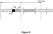
- Figure 5 is an example block diagram illustrating scheduling of PDSCH repetition.
- the filled block 502 indicates a DL assignment on PDCCH, while the hatched blocks (e.g., 504) indicate two PDSCH repetitions where the first repetition is 6-OFDM symbols long (including PDCCH symbols), and the second repetition is 8-OFDM symbols long.
- a mini-slot can have length 8.
- the transmission occasion crossing the slot border is dropped instead of shortened. This means than in Figure 3 above, the first occasion will not be transmitted, but the second and third will.
- Figure 1 shows the case of a first pair of start and length values that violate the time-domain allocation restrictions since the first of K repetitions sent with PUSCH duration of 4 OFDM symbols is not allowed because the first repetition would cross the slot border.
- the network realizing that sending the grant using the specific DCI shown in Figure 1 will cause this problem, can decide that the first of the K repetitions will be sent with 2-symbol duration but send the remaining K-1 repetitions according to the embodiments provided by the scenarios below:
- the concept of the disclosed embodiments also allows another embodiment wherein a UE is scheduled with resources for sending a first of K transport block repetitions, wherein the first pair of start and length values (as indicated by DCI and repetition duration) does not violate the time-domain allocation restrictions but the transmission of one or more of the subsequent repetitions is not possible due to border constraints.
- An additional embodiment is where an uplink transmission is performed using a combination of K repetitions wherein some reflect the nominal 4 symbol duration per TTI and some do not:
- An additional embodiment involves the concept of K transport block repetitions within the context of Semi-Permanent Scheduling (SPS) instead of dynamic grants (as discussed above), wherein the corresponding periodic preconfigured uplink transmission opportunities may be determined without taking into account the time of day at which a UE may typically be expected to have uplink payload available for transmission.
- SPS Semi-Permanent Scheduling
- the UE should be allowed to trigger uplink data transmission as soon as possible (within the scope of its SPS resources) after the data becomes available.
- This delay between data availability and start of data transmission is known as the alignment delay and it can be minimized by allowing transmission of the first of K TB repetitions to start using any symbol within the set of symbols comprising its configured SPS resources.
- FIG. 6 is a block diagram illustrating an example wireless network.
- a wireless network such as the example wireless network illustrated in Figure 6 .
- the wireless network of Figure 6 only depicts network 606, network nodes 660 and 660b, and WDs 610, 610b, and 610c.
- a wireless network may further include any additional elements suitable to support communication between wireless devices or between a wireless device and another communication device, such as a landline telephone, a service provider, or any other network node or end device.
- network node 660 and wireless device (WD) 610 are depicted with additional detail.
- the wireless network may provide communication and other types of services to one or more wireless devices to facilitate the wireless devices' access to and/or use of the services provided by, or via, the wireless network.
- network node refers to equipment capable, configured, arranged and/or operable to communicate directly or indirectly with a wireless device and/or with other network nodes or equipment in the wireless network to enable and/or provide wireless access to the wireless device and/or to perform other functions (e.g., administration) in the wireless network.
- network nodes include, but are not limited to, access points (APs) (e.g., radio access points), base stations (BSs) (e.g., radio base stations, Node Bs, evolved Node Bs (eNBs) and NR NodeBs (gNBs)).
- APs access points
- BSs base stations
- eNBs evolved Node Bs
- gNBs NR NodeBs
- Base stations may be categorized based on the amount of coverage they provide (or, stated differently, their transmit power level) and may then also be referred to as femto base stations, pico base stations, micro base stations, or macro base stations.
- a base station may be a relay node or a relay donor node controlling a relay.
- a network node may also include one or more (or all) parts of a distributed radio base station such as centralized digital units and/or remote radio units (RRUs), sometimes referred to as Remote Radio Heads (RRHs). Such remote radio units may or may not be integrated with an antenna as an antenna integrated radio.
- RRUs remote radio units
- RRHs Remote Radio Heads
- Such remote radio units may or may not be integrated with an antenna as an antenna integrated radio.
- Parts of a distributed radio base station may also be referred to as nodes in a distributed antenna system (DAS).
- DAS distributed antenna system
- network nodes include multi-standard radio (MSR) equipment such as MSR BSs, network controllers such as radio network controllers (RNCs) or base station controllers (BSCs), base transceiver stations (BTSs), transmission points, transmission nodes, multi-cell/multicast coordination entities (MCEs), core network nodes (e.g., MSCs, MMEs), O&M nodes, OSS nodes, SON nodes, positioning nodes (e.g., E-SMLCs), and/or MDTs.
- MSR multi-standard radio
- RNCs radio network controllers
- BSCs base station controllers
- BTSs base transceiver stations
- transmission points transmission nodes
- MCEs multi-cell/multicast coordination entities
- core network nodes e.g., MSCs, MMEs
- O&M nodes e.g., OSS nodes, SON nodes, positioning nodes (e.g., E-SMLCs), and/or MDTs.
- network nodes may represent any suitable device (or group of devices) capable, configured, arranged, and/or operable to enable and/or provide a wireless device with access to the wireless network or to provide some service to a wireless device that has accessed the wireless network.
- network node 660 includes processing circuitry 670, device readable medium 680, interface 690, auxiliary equipment 684, power source 686, power circuitry 687, and antenna 662.
- network node 660 illustrated in the example wireless network of Figure 6 may represent a device that includes the illustrated combination of hardware components, other embodiments may comprise network nodes with different combinations of components. It is to be understood that a network node comprises any suitable combination of hardware and/or software needed to perform the tasks, features, functions and methods disclosed herein.
- network node 660 may comprise multiple different physical components that make up a single illustrated component (e.g., device readable medium 680 may comprise multiple separate hard drives as well as multiple RAM modules).
- network node 660 may be composed of multiple physically separate components (e.g., a NodeB component and a RNC component, or a BTS component and a BSC component, etc.), which may each have their own respective components.
- network node 660 comprises multiple separate components (e.g., BTS and BSC components)
- one or more of the separate components may be shared among several network nodes.
- a single RNC may control multiple NodeB's.
- each unique NodeB and RNC pair may in some instances be considered a single separate network node.
- network node 660 may be configured to support multiple radio access technologies (RATs).
- RATs radio access technologies
- Network node 660 may also include multiple sets of the various illustrated components for different wireless technologies integrated into network node 660, such as, for example, GSM, WCDMA, LTE, NR, WiFi, or Bluetooth wireless technologies. These wireless technologies may be integrated into the same or different chip or set of chips and other components within network node 660.
- Processing circuitry 670 is configured to perform any determining, calculating, or similar operations (e.g., certain obtaining operations) described herein as being provided by a network node. These operations performed by processing circuitry 670 may include processing information obtained by processing circuitry 670 by, for example, converting the obtained information into other information, comparing the obtained information or converted information to information stored in the network node, and/or performing one or more operations based on the obtained information or converted information, and as a result of said processing making a determination.
- processing information obtained by processing circuitry 670 by, for example, converting the obtained information into other information, comparing the obtained information or converted information to information stored in the network node, and/or performing one or more operations based on the obtained information or converted information, and as a result of said processing making a determination.
- Processing circuitry 670 may comprise a combination of one or more of a microprocessor, controller, microcontroller, central processing unit, digital signal processor, application-specific integrated circuit, field programmable gate array, or any other suitable computing device, resource, or combination of hardware, software and/or encoded logic operable to provide, either alone or in conjunction with other network node 660 components, such as device readable medium 680, network node 660 functionality.
- processing circuitry 670 may execute instructions stored in device readable medium 680 or in memory within processing circuitry 670. Such functionality may include providing any of the various wireless features, functions, or benefits discussed herein.
- processing circuitry 670 may include a system on a chip (SOC).
- SOC system on a chip
- processing circuitry 670 may include one or more of radio frequency (RF) transceiver circuitry 672 and baseband processing circuitry 674.
- radio frequency (RF) transceiver circuitry 672 and baseband processing circuitry 674 may be on separate chips (or sets of chips), boards, or units, such as radio units and digital units.
- part or all of RF transceiver circuitry 672 and baseband processing circuitry 674 may be on the same chip or set of chips, boards, or units
- processing circuitry 670 executing instructions stored on device readable medium 680 or memory within processing circuitry 670.
- some or all of the functionality may be provided by processing circuitry 670 without executing instructions stored on a separate or discrete device readable medium, such as in a hard-wired manner.
- processing circuitry 670 can be configured to perform the described functionality. The benefits provided by such functionality are not limited to processing circuitry 670 alone or to other components of network node 660, but are enjoyed by network node 660 as a whole, and/or by end users and the wireless network generally.
- Device readable medium 680 may comprise any form of volatile or non-volatile computer readable memory including, without limitation, persistent storage, solid-state memory, remotely mounted memory, magnetic media, optical media, random access memory (RAM), read-only memory (ROM), mass storage media (for example, a hard disk), removable storage media (for example, a flash drive, a Compact Disk (CD) or a Digital Video Disk (DVD)), and/or any other volatile or non-volatile, non-transitory device readable and/or computer-executable memory devices that store information, data, and/or instructions that may be used by processing circuitry 670.
- volatile or non-volatile computer readable memory including, without limitation, persistent storage, solid-state memory, remotely mounted memory, magnetic media, optical media, random access memory (RAM), read-only memory (ROM), mass storage media (for example, a hard disk), removable storage media (for example, a flash drive, a Compact Disk (CD) or a Digital Video Disk (DVD)), and/or any other volatile or
- Device readable medium 680 may store any suitable instructions, data or information, including a computer program, software, an application including one or more of logic, rules, code, tables, etc. and/or other instructions capable of being executed by processing circuitry 670 and, utilized by network node 660.
- Device readable medium 680 may be used to store any calculations made by processing circuitry 670 and/or any data received via interface 690.
- processing circuitry 670 and device readable medium 680 may be considered to be integrated.
- Interface 690 is used in the wired or wireless communication of signalling and/or data between network node 660, network 606, and/or WDs 610. As illustrated, interface 690 comprises port(s)/terminal(s) 694 to send and receive data, for example to and from network 606 over a wired connection. Interface 690 also includes radio front end circuitry 692 that may be coupled to, or in certain embodiments a part of, antenna 662. Radio front end circuitry 692 comprises filters 698 and amplifiers 696. Radio front end circuitry 692 may be connected to antenna 662 and processing circuitry 670. Radio front end circuitry may be configured to condition signals communicated between antenna 662 and processing circuitry 670.
- Radio front end circuitry 692 may receive digital data that is to be sent out to other network nodes or WDs via a wireless connection. Radio front end circuitry 692 may convert the digital data into a radio signal having the appropriate channel and bandwidth parameters using a combination of filters 698 and/or amplifiers 696. The radio signal may then be transmitted via antenna 662. Similarly, when receiving data, antenna 662 may collect radio signals which are then converted into digital data by radio front end circuitry 692. The digital data may be passed to processing circuitry 670. In other embodiments, the interface may comprise different components and/or different combinations of components.
- network node 660 may not include separate radio front end circuitry 692, instead, processing circuitry 670 may comprise radio front end circuitry and may be connected to antenna 662 without separate radio front end circuitry 692.
- processing circuitry 670 may comprise radio front end circuitry and may be connected to antenna 662 without separate radio front end circuitry 692.
- all or some of RF transceiver circuitry 672 may be considered a part of interface 690.
- interface 690 may include one or more ports or terminals 694, radio front end circuitry 692, and RF transceiver circuitry 672, as part of a radio unit (not shown), and interface 690 may communicate with baseband processing circuitry 674, which is part of a digital unit (not shown).
- Antenna 662 may include one or more antennas, or antenna arrays, configured to send and/or receive wireless signals. Antenna 662 may be coupled to radio front end circuitry 690 and may be any type of antenna capable of transmitting and receiving data and/or signals wirelessly. In some embodiments, antenna 662 may comprise one or more omni-directional, sector or panel antennas operable to transmit/receive radio signals between, for example, 2 GHz and 66 GHz. An omni-directional antenna may be used to transmit/receive radio signals in any direction, a sector antenna may be used to transmit/receive radio signals from devices within a particular area, and a panel antenna may be a line of sight antenna used to transmit/receive radio signals in a relatively straight line. In some instances, the use of more than one antenna may be referred to as MIMO. In certain embodiments, antenna 662 may be separate from network node 660 and may be connectable to network node 660 through an interface or port.
- Antenna 662, interface 690, and/or processing circuitry 670 may be configured to perform any receiving operations and/or certain obtaining operations described herein as being performed by a network node. Any information, data and/or signals may be received from a wireless device, another network node and/or any other network equipment. Similarly, antenna 662, interface 690, and/or processing circuitry 670 may be configured to perform any transmitting operations described herein as being performed by a network node. Any information, data and/or signals may be transmitted to a wireless device, another network node and/or any other network equipment.
- Power circuitry 687 may comprise, or be coupled to, power management circuitry and is configured to supply the components of network node 660 with power for performing the functionality described herein. Power circuitry 687 may receive power from power source 686. Power source 686 and/or power circuitry 687 may be configured to provide power to the various components of network node 660 in a form suitable for the respective components (e.g., at a voltage and current level needed for each respective component). Power source 686 may either be included in, or external to, power circuitry 687 and/or network node 660.
- network node 660 may be connectable to an external power source (e.g., an electricity outlet) via an input circuitry or interface such as an electrical cable, whereby the external power source supplies power to power circuitry 687.
- power source 686 may comprise a source of power in the form of a battery or battery pack which is connected to, or integrated in, power circuitry 687. The battery may provide backup power should the external power source fail.
- Other types of power sources such as photovoltaic devices, may also be used.
- network node 660 may include additional components beyond those shown in Figure 6 that may be responsible for providing certain aspects of the network node's functionality, including any of the functionality described herein and/or any functionality necessary to support the subject matter described herein.
- network node 660 may include user interface equipment to allow input of information into network node 660 and to allow output of information from network node 660. This may allow a user to perform diagnostic, maintenance, repair, and other administrative functions for network node 660.
- wireless device refers to a device capable, configured, arranged and/or operable to communicate wirelessly with network nodes and/or other wireless devices.
- the term WD may be used interchangeably herein with user equipment (UE).
- Communicating wirelessly may involve transmitting and/or receiving wireless signals using electromagnetic waves, radio waves, infrared waves, and/or other types of signals suitable for conveying information through air.
- a WD may be configured to transmit and/or receive information without direct human interaction.
- a WD may be designed to transmit information to a network on a predetermined schedule, when triggered by an internal or external event, or in response to requests from the network.
Landscapes
- Engineering & Computer Science (AREA)
- Signal Processing (AREA)
- Computer Networks & Wireless Communication (AREA)
- Mobile Radio Communication Systems (AREA)
- Transition And Organic Metals Composition Catalysts For Addition Polymerization (AREA)
- Developing Agents For Electrophotography (AREA)
Claims (13)
- Verfahren, das von einer drahtlosen Vorrichtung (610) durchgeführt wird, zum Senden von Transportblockwiederholungen, wobei das Verfahren Folgendes umfasst:Empfangen (702) einer dynamischen Gewährung oder Downlink-Zuordnung, die ein erstes Paar von Start- und Längenwerten zum Starten der Übertragung einer ersten von K Transportblockwiederholungen bereitstellt, was zu einer Verletzung einer Zeitbereichszuweisungsbeschränkung führt, wobei die Zeitbereichszuweisungsbeschränkung eine Slot-Grenze ist;Bestimmen (704) eines zweiten Paars von Start- und Längenwerten zum Starten der Übertragung, sodass die Zeitbereichszuweisungsbeschränkung nicht verletzt wird, wobei der Startwert des zweiten Paars größer oder gleich dem Startwert des ersten Paars ist und der Längenwert des zweiten Paars kleiner als der Längenwert des ersten Paars ist; undÜbertragen (706) der K Transportblockwiederholungen gemäß dem bestimmten zweiten Paar von Start- und Längenwerten,wobei die Bestimmung (704) des zweiten Paars von Start- und Längenwerten auf einem Standort der Slot-Grenze basiert.
- Verfahren nach Anspruch 1, wobei das zweite Paar von Start- und Längenwerten derart bestimmt wird, dass der Startwert des zweiten Paars der gleiche wie der Startwert des ersten Paars ist, aber der Längenwert des zweiten Paars an den Standort der Slot-Grenze angepasst wird.
- Verfahren nach Anspruch 1, wobei das zweite Paar von Start- und Längenwerten derart bestimmt wird, dass der Startwert des zweiten Paars und der Längenwert des zweiten Paars an den Standort der Slot-Grenze angepasst werden.
- Verfahren nach Anspruch 1, wobei die Bestimmung des zweiten Paars von Start- und Längenwerten auf dem Standort der Slot-Grenze und dem Längenwert des ersten Paars basiert.
- Verfahren nach Anspruch 4, wobei, wenn sich die Slot-Grenze in einer ersten Hälfte von einer der K Transportblockwiederholungen befindet, das zweite Paar von Start- und Längenwerten durch Verzögern des Startwerts des zweiten Paars und Anpassen des Längenwerts des zweiten Paars, um mit dem Standort der Slot-Grenze übereinzustimmen, bestimmt wird.
- Verfahren nach Anspruch 4, wobei, wenn sich die Slot-Grenze in einer zweiten Hälfte oder in einer Mitte von einer der K Transportblockwiederholungen befindet, das zweite Paar von Start- und Längenwerten durch Beibehalten des Startwerts des zweiten Paars wie der Startwert des ersten Paars bestimmt wird, jedoch durch Anpassen des Längenwerts des zweiten Paars, um innerhalb des Standorts der Slot-Grenze zu passen.
- Drahtlose Vorrichtung (610), umfassend eine Verarbeitungsschaltung (620) und ein(en) von einem Gerät lesbares Medium (630) oder lesbaren Speicher, wobei die Verarbeitungsschaltung (620) dazu konfiguriert ist, Anweisungen auszuführen, die auf dem von der Vorrichtung lesbaren Medium (630) oder Speicher gespeichert sind, um Vorgänge durchzuführen, die Folgendes umfassen:Empfangen einer dynamischen Gewährung oder Downlink-Zuordnung, die ein erstes Paar von Start- und Längenwerten zum Starten der Übertragung einer ersten von K Transportblockwiederholungen bereitstellt, was zu einer Verletzung einer Zeitbereichszuweisungsbeschränkung führt, wobei die Zeitbereichszuweisungsbeschränkung eine Slot-Grenze ist;Bestimmen eines zweiten Paars von Start- und Längenwerten zum Starten der Übertragung, sodass die Zeitbereichszuweisungsbeschränkung nicht verletzt wird, wobei der Startwert des zweiten Paars größer oder gleich dem Startwert des ersten Paars ist und der Längenwert des zweiten Paars kleiner als der Längenwert des ersten Paars ist; undÜbertragen der K Transportblockwiederholungen gemäß dem bestimmten zweiten Paar von Start- und Längenwerten, wobei die Bestimmung des zweiten Paars von Start- und Längenwerten auf einem Standort der Slot-Grenze basiert.
- Drahtlose Vorrichtung (610) nach Anspruch 7, die dazu konfiguriert ist, das zweite Paar von Start- und Längenwerten derart zu bestimmen, dass der Startwert des zweiten Paars der gleiche wie der Startwert des ersten Paars ist, aber der Längenwert des zweiten Paars an den Standort der Slot-Grenze angepasst wird.
- Drahtlose Vorrichtung (610) nach Anspruch 7, die dazu konfiguriert ist, das zweite Paar von Start- und Längenwerten derart zu bestimmen, dass der Startwert des zweiten Paars und der Längenwert des zweiten Paars an den Standort der Slot-Grenze angepasst werden.
- Drahtlose Vorrichtung (610) nach Anspruch 7, die dazu konfiguriert ist, das zweite Paar von Start- und Längenwerten auf Grundlage des Standorts der Slot-Grenze und des Längenwerts des ersten Paars zu bestimmen.
- Drahtlose Vorrichtung (610) nach Anspruch 10, wobei, wenn sich die Slot-Grenze in einer ersten Hälfte von einer der K Transportblockwiederholungen befindet, die drahtlose Vorrichtung (610) dazu konfiguriert ist, das zweite Paar von Start- und Längenwerten durch Verzögern des Startwerts des zweiten Paars und Anpassen des Längenwerts des zweiten Paars zu bestimmen, um mit dem Standort der Slot-Grenze übereinzustimmen.
- Drahtlose Vorrichtung (610) nach Anspruch 10, wobei, wenn sich die Slot-Grenze in einer zweiten Hälfte oder in einer Mitte von einer der K Transportblockwiederholungen befindet, die drahtlose Vorrichtung (610) dazu konfiguriert ist, das zweite Paar von Start- und Längenwerten durch Beibehalten des Startwerts des zweiten Paars wie der Startwert des ersten Paars zu bestimmen, jedoch durch Anpassen des Längenwerts des zweiten Paars, um innerhalb des Standorts der Slot-Grenze zu passen.
- Von einer Vorrichtung lesbares Medium (630), auf dem Anweisungen gespeichert sind, die bei Ausführung durch eine Verarbeitungsschaltung (620) einer drahtlosen Vorrichtung (610) die drahtlose Vorrichtung (610) zu Folgendem veranlassen:Empfangen einer dynamischen Gewährung oder Downlink-Zuordnung, die ein erstes Paar von Start- und Längenwerten zum Starten der Übertragung einer ersten von K Transportblockwiederholungen bereitstellt, was zu einer Verletzung einer Zeitbereichszuweisungsbeschränkung führt, wobei die Zeitbereichszuweisungsbeschränkung eine Slot-Grenze ist;Bestimmen eines zweiten Paars von Start- und Längenwerten zum Starten der Übertragung, sodass die Zeitbereichszuweisungsbeschränkung nicht verletzt wird, wobei der Startwert des zweiten Paars größer oder gleich dem Startwert des ersten Paars ist und der Längenwert des zweiten Paars kleiner als der Längenwert des ersten Paars ist; undÜbertragen der K Transportblockwiederholungen gemäß dem bestimmten zweiten Paar von Start- und Längenwerten, wobei die Bestimmung des zweiten Paars von Start- und Längenwerten auf einem Standort der Slot-Grenze basiert.
Applications Claiming Priority (3)
| Application Number | Priority Date | Filing Date | Title |
|---|---|---|---|
| US201862661552P | 2018-04-23 | 2018-04-23 | |
| PCT/IB2019/053354 WO2019207488A1 (en) | 2018-04-23 | 2019-04-23 | Time-domain allocation for repititions |
| EP19727731.2A EP3785388B1 (de) | 2018-04-23 | 2019-04-23 | Zeitbereichszuordnung für wiederholungen |
Related Parent Applications (2)
| Application Number | Title | Priority Date | Filing Date |
|---|---|---|---|
| EP19727731.2A Division EP3785388B1 (de) | 2018-04-23 | 2019-04-23 | Zeitbereichszuordnung für wiederholungen |
| EP19727731.2A Division-Into EP3785388B1 (de) | 2018-04-23 | 2019-04-23 | Zeitbereichszuordnung für wiederholungen |
Publications (4)
| Publication Number | Publication Date |
|---|---|
| EP4236173A2 EP4236173A2 (de) | 2023-08-30 |
| EP4236173A3 EP4236173A3 (de) | 2023-09-27 |
| EP4236173C0 EP4236173C0 (de) | 2025-07-02 |
| EP4236173B1 true EP4236173B1 (de) | 2025-07-02 |
Family
ID=66677185
Family Applications (2)
| Application Number | Title | Priority Date | Filing Date |
|---|---|---|---|
| EP19727731.2A Active EP3785388B1 (de) | 2018-04-23 | 2019-04-23 | Zeitbereichszuordnung für wiederholungen |
| EP23176911.8A Active EP4236173B1 (de) | 2018-04-23 | 2019-04-23 | Zeitbereichszuordnung für wiederholungen |
Family Applications Before (1)
| Application Number | Title | Priority Date | Filing Date |
|---|---|---|---|
| EP19727731.2A Active EP3785388B1 (de) | 2018-04-23 | 2019-04-23 | Zeitbereichszuordnung für wiederholungen |
Country Status (7)
| Country | Link |
|---|---|
| US (2) | US11510196B2 (de) |
| EP (2) | EP3785388B1 (de) |
| JP (1) | JP7135110B2 (de) |
| CN (1) | CN111971916B (de) |
| ES (2) | ES3037829T3 (de) |
| RU (1) | RU2754583C1 (de) |
| WO (1) | WO2019207488A1 (de) |
Families Citing this family (15)
| Publication number | Priority date | Publication date | Assignee | Title |
|---|---|---|---|---|
| US11510184B2 (en) * | 2018-07-03 | 2022-11-22 | Qualcomm Incorporated | Physical uplink control channel repetition |
| CN110831218B (zh) * | 2018-08-10 | 2021-07-23 | 大唐移动通信设备有限公司 | 一种信息传输方法、基站及终端 |
| JP7195406B2 (ja) | 2018-10-12 | 2022-12-23 | オッポ広東移動通信有限公司 | 情報を繰り返し伝送する方法、端末機器及びネットワーク機器 |
| CN111181707B (zh) * | 2018-11-09 | 2022-11-04 | 华为技术有限公司 | 数据传输的方法和通信装置 |
| EP3915327A1 (de) * | 2019-02-12 | 2021-12-01 | Google LLC | System und verfahren zur reduzierung der verzögerungen von zeitgeberbasierten übertragungen auf einem gemeinsamen träger |
| US11617198B2 (en) | 2019-02-15 | 2023-03-28 | Qualcomm Incorporated | Physical uplink shared channel repetition across slot boundary |
| US11641249B2 (en) * | 2019-03-25 | 2023-05-02 | Lenovo (Singapore) Pte. Ltd. | Method and apparatus for determining a duration of a repetition of a transport block |
| JP7501544B2 (ja) * | 2019-07-01 | 2024-06-18 | ソニーグループ株式会社 | 通信デバイス、インフラストラクチャ機器および方法 |
| CN115702558A (zh) * | 2020-06-04 | 2023-02-14 | 联想(新加坡)私人有限公司 | 传输块的集合的时域重复 |
| WO2022016414A1 (en) * | 2020-07-22 | 2022-01-27 | Qualcomm Incorporated | Repetition in a configured grant |
| WO2022080941A1 (ko) * | 2020-10-15 | 2022-04-21 | 엘지전자 주식회사 | 커버리지 개선을 위한 pucch 전송 |
| WO2022133754A1 (zh) * | 2020-12-22 | 2022-06-30 | 华为技术有限公司 | 发送数据和接收数据的方法以及通信装置 |
| US12200705B2 (en) * | 2021-01-06 | 2025-01-14 | Qualcomm Incorporated | Latency reduction and coverage enhancement for extended reality |
| WO2022165836A1 (zh) * | 2021-02-08 | 2022-08-11 | 华为技术有限公司 | 传输方法及通信装置 |
| US12323971B2 (en) * | 2021-07-06 | 2025-06-03 | Acer Incorporated | Device of handling PUSCH transmissions |
Family Cites Families (15)
| Publication number | Priority date | Publication date | Assignee | Title |
|---|---|---|---|---|
| WO2010122419A2 (en) * | 2009-04-22 | 2010-10-28 | Nokia Corporation | Methods and apparatus for subframe splitting to obtain uplink feedback using relay nodes |
| EP2721792B1 (de) * | 2011-06-15 | 2019-04-17 | Samsung Electronics Co., Ltd. | Erweiterung einer physikalischen downlink-steuersignalgebung in einem kommunikationssystem |
| US9113463B2 (en) * | 2011-11-04 | 2015-08-18 | Qualcomm Incorporated | Resource management for enhanced PDCCH |
| US9544119B2 (en) * | 2011-11-23 | 2017-01-10 | Lg Electronics Inc. | Method and device for transmitting/obtaining control information in wireless communication system |
| US20140098754A1 (en) * | 2012-10-09 | 2014-04-10 | Qualcomm Incorporated | Methods and apparatus for improved resource management in lte |
| WO2015077915A1 (en) * | 2013-11-26 | 2015-06-04 | Qualcomm Incorporated | Methods and apparatus for capacity enhancements for voice over long term evolution |
| US10080218B2 (en) | 2014-03-04 | 2018-09-18 | Lg Electronics Inc. | Method of receiving control information for receiving discovery reference signal and apparatus thereof |
| CN104468030B (zh) | 2014-08-26 | 2018-06-05 | 上海华为技术有限公司 | 一种数据传输方法、用户设备及基站 |
| WO2016153548A1 (en) * | 2015-03-26 | 2016-09-29 | Intel IP Corporation | Systems, methods and devices for uplink transmissions with reduced signaling overhead |
| US10085255B2 (en) * | 2015-09-02 | 2018-09-25 | Qualcomm Incorporated | Physical uplink control channel for low latency downlink communications |
| WO2019155637A1 (ja) * | 2018-02-09 | 2019-08-15 | 株式会社Nttドコモ | 送信装置、受信装置及び無線通信方法 |
| US11025373B2 (en) * | 2018-05-11 | 2021-06-01 | Qualcomm Incorporated | Repetition-based transmission |
| US11139930B2 (en) * | 2018-08-10 | 2021-10-05 | Institute For Information Industry | User equipment and method for performing repetition |
| US11540312B2 (en) * | 2018-09-25 | 2022-12-27 | Mediatek Singapore Pte. Ltd. | Method and apparatus for handling multiple active configurations of configured grant in mobile communications |
| US11831571B2 (en) * | 2018-10-31 | 2023-11-28 | Qualcomm Incorporated | Transport block transmission using different spatial parameters |
-
2019
- 2019-04-23 US US16/964,231 patent/US11510196B2/en active Active
- 2019-04-23 EP EP19727731.2A patent/EP3785388B1/de active Active
- 2019-04-23 JP JP2020558520A patent/JP7135110B2/ja active Active
- 2019-04-23 CN CN201980025441.8A patent/CN111971916B/zh active Active
- 2019-04-23 ES ES23176911T patent/ES3037829T3/es active Active
- 2019-04-23 WO PCT/IB2019/053354 patent/WO2019207488A1/en not_active Ceased
- 2019-04-23 ES ES19727731T patent/ES2950668T3/es active Active
- 2019-04-23 EP EP23176911.8A patent/EP4236173B1/de active Active
- 2019-04-23 RU RU2020137943A patent/RU2754583C1/ru active
-
2022
- 2022-11-10 US US17/984,375 patent/US11910367B2/en active Active
Also Published As
| Publication number | Publication date |
|---|---|
| US20210045110A1 (en) | 2021-02-11 |
| JP2021522712A (ja) | 2021-08-30 |
| EP4236173A3 (de) | 2023-09-27 |
| EP4236173C0 (de) | 2025-07-02 |
| EP4236173A2 (de) | 2023-08-30 |
| ES2950668T3 (es) | 2023-10-11 |
| WO2019207488A1 (en) | 2019-10-31 |
| RU2754583C1 (ru) | 2021-09-03 |
| CN111971916A (zh) | 2020-11-20 |
| JP7135110B2 (ja) | 2022-09-12 |
| CN111971916B (zh) | 2023-08-22 |
| EP3785388C0 (de) | 2023-07-12 |
| ES3037829T3 (en) | 2025-10-07 |
| EP3785388A1 (de) | 2021-03-03 |
| US11910367B2 (en) | 2024-02-20 |
| EP3785388B1 (de) | 2023-07-12 |
| US20230070829A1 (en) | 2023-03-09 |
| US11510196B2 (en) | 2022-11-22 |
Similar Documents
| Publication | Publication Date | Title |
|---|---|---|
| US11910367B2 (en) | Time-domain allocation for repetitions | |
| US20250175855A1 (en) | Transmit format for multi-segment pusch | |
| US11849420B2 (en) | Systems and methods for synchronous control of HARQ configurations | |
| US12369176B2 (en) | Transport block size determination for repetition | |
| AU2021320067B2 (en) | Coverage enhancement of Msg3 and MsgA transmissions on physical uplink shared channel | |
| WO2022022286A2 (en) | Method and apparatus for transmitting csi report | |
| CN112970214B (zh) | 用于侧链路的反馈信令 | |
| RU2726641C1 (ru) | Сигнализация о местоположении опорных сигналов в слотах и минислотах | |
| JP7250038B2 (ja) | 早期データ送信のためのトランスポートブロックサイズ選択 | |
| CN115242364A (zh) | 用于监控的方法和设备 | |
| CN108293245B (zh) | 一种数据通信的方法、终端设备及网络设备 | |
| CN109952802B (zh) | 用于发送下行链路控制信息的方法和设备 | |
| WO2017152810A1 (zh) | 信道探测信号srs的发送方法及装置 | |
| HK40032916A (en) | Methods, wireless device, base station, media, and system for communicating transport block repetitions | |
| WO2020208216A1 (en) | Multiple starting positions for multi-transmission time interval scheduling downlink control information | |
| HK40032916B (zh) | 用於传送传输块重复的方法、无线设备、基站、介质和系统 | |
| US20240365295A1 (en) | Methods and devices for semi-persistently scheduled transmission |
Legal Events
| Date | Code | Title | Description |
|---|---|---|---|
| PUAI | Public reference made under article 153(3) epc to a published international application that has entered the european phase |
Free format text: ORIGINAL CODE: 0009012 |
|
| STAA | Information on the status of an ep patent application or granted ep patent |
Free format text: STATUS: THE APPLICATION HAS BEEN PUBLISHED |
|
| REG | Reference to a national code |
Ref country code: DE Ref legal event code: R079 Free format text: PREVIOUS MAIN CLASS: H04L0005000000 Ipc: H04L0001080000 Ref document number: 602019072184 Country of ref document: DE |
|
| PUAL | Search report despatched |
Free format text: ORIGINAL CODE: 0009013 |
|
| AC | Divisional application: reference to earlier application |
Ref document number: 3785388 Country of ref document: EP Kind code of ref document: P |
|
| AK | Designated contracting states |
Kind code of ref document: A2 Designated state(s): AL AT BE BG CH CY CZ DE DK EE ES FI FR GB GR HR HU IE IS IT LI LT LU LV MC MK MT NL NO PL PT RO RS SE SI SK SM TR |
|
| AK | Designated contracting states |
Kind code of ref document: A3 Designated state(s): AL AT BE BG CH CY CZ DE DK EE ES FI FR GB GR HR HU IE IS IT LI LT LU LV MC MK MT NL NO PL PT RO RS SE SI SK SM TR |
|
| RIC1 | Information provided on ipc code assigned before grant |
Ipc: H04L 5/00 20060101ALI20230821BHEP Ipc: H04L 1/08 20060101AFI20230821BHEP |
|
| STAA | Information on the status of an ep patent application or granted ep patent |
Free format text: STATUS: REQUEST FOR EXAMINATION WAS MADE |
|
| 17P | Request for examination filed |
Effective date: 20240315 |
|
| RBV | Designated contracting states (corrected) |
Designated state(s): AL AT BE BG CH CY CZ DE DK EE ES FI FR GB GR HR HU IE IS IT LI LT LU LV MC MK MT NL NO PL PT RO RS SE SI SK SM TR |
|
| GRAP | Despatch of communication of intention to grant a patent |
Free format text: ORIGINAL CODE: EPIDOSNIGR1 |
|
| STAA | Information on the status of an ep patent application or granted ep patent |
Free format text: STATUS: GRANT OF PATENT IS INTENDED |
|
| INTG | Intention to grant announced |
Effective date: 20250313 |
|
| GRAS | Grant fee paid |
Free format text: ORIGINAL CODE: EPIDOSNIGR3 |
|
| GRAA | (expected) grant |
Free format text: ORIGINAL CODE: 0009210 |
|
| STAA | Information on the status of an ep patent application or granted ep patent |
Free format text: STATUS: THE PATENT HAS BEEN GRANTED |
|
| AC | Divisional application: reference to earlier application |
Ref document number: 3785388 Country of ref document: EP Kind code of ref document: P |
|
| AK | Designated contracting states |
Kind code of ref document: B1 Designated state(s): AL AT BE BG CH CY CZ DE DK EE ES FI FR GB GR HR HU IE IS IT LI LT LU LV MC MK MT NL NO PL PT RO RS SE SI SK SM TR |
|
| REG | Reference to a national code |
Ref country code: GB Ref legal event code: FG4D |
|
| REG | Reference to a national code |
Ref country code: CH Ref legal event code: EP |
|
| REG | Reference to a national code |
Ref country code: DE Ref legal event code: R096 Ref document number: 602019072184 Country of ref document: DE |
|
| REG | Reference to a national code |
Ref country code: IE Ref legal event code: FG4D |
|
| U01 | Request for unitary effect filed |
Effective date: 20250709 |
|
| U07 | Unitary effect registered |
Designated state(s): AT BE BG DE DK EE FI FR IT LT LU LV MT NL PT RO SE SI Effective date: 20250716 |
|
| REG | Reference to a national code |
Ref country code: ES Ref legal event code: FG2A Ref document number: 3037829 Country of ref document: ES Kind code of ref document: T3 Effective date: 20251007 |