EP4235949A1 - Bloc-batterie à sécurité améliorée - Google Patents
Bloc-batterie à sécurité améliorée Download PDFInfo
- Publication number
- EP4235949A1 EP4235949A1 EP22861743.7A EP22861743A EP4235949A1 EP 4235949 A1 EP4235949 A1 EP 4235949A1 EP 22861743 A EP22861743 A EP 22861743A EP 4235949 A1 EP4235949 A1 EP 4235949A1
- Authority
- EP
- European Patent Office
- Prior art keywords
- bus bar
- battery
- safety bus
- module
- venting gas
- Prior art date
- Legal status (The legal status is an assumption and is not a legal conclusion. Google has not performed a legal analysis and makes no representation as to the accuracy of the status listed.)
- Pending
Links
- 238000013022 venting Methods 0.000 claims abstract description 96
- 229910052751 metal Inorganic materials 0.000 claims description 125
- 239000002184 metal Substances 0.000 claims description 125
- 238000002844 melting Methods 0.000 claims description 30
- 230000008018 melting Effects 0.000 claims description 30
- 238000004146 energy storage Methods 0.000 claims description 12
- 239000007789 gas Substances 0.000 description 94
- 239000010410 layer Substances 0.000 description 39
- RYGMFSIKBFXOCR-UHFFFAOYSA-N Copper Chemical compound [Cu] RYGMFSIKBFXOCR-UHFFFAOYSA-N 0.000 description 22
- 229910052802 copper Inorganic materials 0.000 description 19
- 239000010949 copper Substances 0.000 description 19
- 230000006870 function Effects 0.000 description 19
- 239000000463 material Substances 0.000 description 13
- 229910052782 aluminium Inorganic materials 0.000 description 8
- XAGFODPZIPBFFR-UHFFFAOYSA-N aluminium Chemical compound [Al] XAGFODPZIPBFFR-UHFFFAOYSA-N 0.000 description 8
- 230000000694 effects Effects 0.000 description 8
- 238000009413 insulation Methods 0.000 description 8
- 230000000903 blocking effect Effects 0.000 description 7
- 238000007599 discharging Methods 0.000 description 7
- 230000002265 prevention Effects 0.000 description 7
- 239000004020 conductor Substances 0.000 description 6
- 230000005540 biological transmission Effects 0.000 description 5
- 239000007769 metal material Substances 0.000 description 5
- PXHVJJICTQNCMI-UHFFFAOYSA-N Nickel Chemical compound [Ni] PXHVJJICTQNCMI-UHFFFAOYSA-N 0.000 description 4
- 238000010586 diagram Methods 0.000 description 4
- WHXSMMKQMYFTQS-UHFFFAOYSA-N Lithium Chemical compound [Li] WHXSMMKQMYFTQS-UHFFFAOYSA-N 0.000 description 3
- 229910000831 Steel Inorganic materials 0.000 description 3
- 230000002159 abnormal effect Effects 0.000 description 3
- 229910052744 lithium Inorganic materials 0.000 description 3
- 150000002739 metals Chemical class 0.000 description 3
- 238000012986 modification Methods 0.000 description 3
- 230000004048 modification Effects 0.000 description 3
- 239000010959 steel Substances 0.000 description 3
- 238000010292 electrical insulation Methods 0.000 description 2
- 229910052759 nickel Inorganic materials 0.000 description 2
- UFHFLCQGNIYNRP-UHFFFAOYSA-N Hydrogen Chemical compound [H][H] UFHFLCQGNIYNRP-UHFFFAOYSA-N 0.000 description 1
- 239000011149 active material Substances 0.000 description 1
- 230000000712 assembly Effects 0.000 description 1
- 238000000429 assembly Methods 0.000 description 1
- OJIJEKBXJYRIBZ-UHFFFAOYSA-N cadmium nickel Chemical compound [Ni].[Cd] OJIJEKBXJYRIBZ-UHFFFAOYSA-N 0.000 description 1
- 239000011247 coating layer Substances 0.000 description 1
- 238000004891 communication Methods 0.000 description 1
- 239000012777 electrically insulating material Substances 0.000 description 1
- 239000003792 electrolyte Substances 0.000 description 1
- 239000008151 electrolyte solution Substances 0.000 description 1
- 239000010419 fine particle Substances 0.000 description 1
- 239000001257 hydrogen Substances 0.000 description 1
- 229910052739 hydrogen Inorganic materials 0.000 description 1
- 239000011810 insulating material Substances 0.000 description 1
- 239000012212 insulator Substances 0.000 description 1
- 230000003446 memory effect Effects 0.000 description 1
- 238000000034 method Methods 0.000 description 1
- 239000012768 molten material Substances 0.000 description 1
- QELJHCBNGDEXLD-UHFFFAOYSA-N nickel zinc Chemical compound [Ni].[Zn] QELJHCBNGDEXLD-UHFFFAOYSA-N 0.000 description 1
- 239000002245 particle Substances 0.000 description 1
- 230000000149 penetrating effect Effects 0.000 description 1
- 239000002861 polymer material Substances 0.000 description 1
- 239000000843 powder Substances 0.000 description 1
- 238000011160 research Methods 0.000 description 1
- 239000000243 solution Substances 0.000 description 1
Images


Classifications
-
- H—ELECTRICITY
- H01—ELECTRIC ELEMENTS
- H01M—PROCESSES OR MEANS, e.g. BATTERIES, FOR THE DIRECT CONVERSION OF CHEMICAL ENERGY INTO ELECTRICAL ENERGY
- H01M50/00—Constructional details or processes of manufacture of the non-active parts of electrochemical cells other than fuel cells, e.g. hybrid cells
- H01M50/20—Mountings; Secondary casings or frames; Racks, modules or packs; Suspension devices; Shock absorbers; Transport or carrying devices; Holders
- H01M50/249—Mountings; Secondary casings or frames; Racks, modules or packs; Suspension devices; Shock absorbers; Transport or carrying devices; Holders specially adapted for aircraft or vehicles, e.g. cars or trains
-
- H—ELECTRICITY
- H01—ELECTRIC ELEMENTS
- H01M—PROCESSES OR MEANS, e.g. BATTERIES, FOR THE DIRECT CONVERSION OF CHEMICAL ENERGY INTO ELECTRICAL ENERGY
- H01M50/00—Constructional details or processes of manufacture of the non-active parts of electrochemical cells other than fuel cells, e.g. hybrid cells
- H01M50/20—Mountings; Secondary casings or frames; Racks, modules or packs; Suspension devices; Shock absorbers; Transport or carrying devices; Holders
- H01M50/204—Racks, modules or packs for multiple batteries or multiple cells
-
- H—ELECTRICITY
- H01—ELECTRIC ELEMENTS
- H01M—PROCESSES OR MEANS, e.g. BATTERIES, FOR THE DIRECT CONVERSION OF CHEMICAL ENERGY INTO ELECTRICAL ENERGY
- H01M50/00—Constructional details or processes of manufacture of the non-active parts of electrochemical cells other than fuel cells, e.g. hybrid cells
- H01M50/20—Mountings; Secondary casings or frames; Racks, modules or packs; Suspension devices; Shock absorbers; Transport or carrying devices; Holders
- H01M50/258—Modular batteries; Casings provided with means for assembling
-
- H—ELECTRICITY
- H01—ELECTRIC ELEMENTS
- H01M—PROCESSES OR MEANS, e.g. BATTERIES, FOR THE DIRECT CONVERSION OF CHEMICAL ENERGY INTO ELECTRICAL ENERGY
- H01M50/00—Constructional details or processes of manufacture of the non-active parts of electrochemical cells other than fuel cells, e.g. hybrid cells
- H01M50/20—Mountings; Secondary casings or frames; Racks, modules or packs; Suspension devices; Shock absorbers; Transport or carrying devices; Holders
- H01M50/296—Mountings; Secondary casings or frames; Racks, modules or packs; Suspension devices; Shock absorbers; Transport or carrying devices; Holders characterised by terminals of battery packs
-
- H—ELECTRICITY
- H01—ELECTRIC ELEMENTS
- H01M—PROCESSES OR MEANS, e.g. BATTERIES, FOR THE DIRECT CONVERSION OF CHEMICAL ENERGY INTO ELECTRICAL ENERGY
- H01M50/00—Constructional details or processes of manufacture of the non-active parts of electrochemical cells other than fuel cells, e.g. hybrid cells
- H01M50/30—Arrangements for facilitating escape of gases
- H01M50/35—Gas exhaust passages comprising elongated, tortuous or labyrinth-shaped exhaust passages
-
- H—ELECTRICITY
- H01—ELECTRIC ELEMENTS
- H01M—PROCESSES OR MEANS, e.g. BATTERIES, FOR THE DIRECT CONVERSION OF CHEMICAL ENERGY INTO ELECTRICAL ENERGY
- H01M50/00—Constructional details or processes of manufacture of the non-active parts of electrochemical cells other than fuel cells, e.g. hybrid cells
- H01M50/50—Current conducting connections for cells or batteries
- H01M50/502—Interconnectors for connecting terminals of adjacent batteries; Interconnectors for connecting cells outside a battery casing
- H01M50/503—Interconnectors for connecting terminals of adjacent batteries; Interconnectors for connecting cells outside a battery casing characterised by the shape of the interconnectors
-
- H—ELECTRICITY
- H01—ELECTRIC ELEMENTS
- H01M—PROCESSES OR MEANS, e.g. BATTERIES, FOR THE DIRECT CONVERSION OF CHEMICAL ENERGY INTO ELECTRICAL ENERGY
- H01M50/00—Constructional details or processes of manufacture of the non-active parts of electrochemical cells other than fuel cells, e.g. hybrid cells
- H01M50/50—Current conducting connections for cells or batteries
- H01M50/502—Interconnectors for connecting terminals of adjacent batteries; Interconnectors for connecting cells outside a battery casing
- H01M50/507—Interconnectors for connecting terminals of adjacent batteries; Interconnectors for connecting cells outside a battery casing comprising an arrangement of two or more busbars within a container structure, e.g. busbar modules
-
- H—ELECTRICITY
- H01—ELECTRIC ELEMENTS
- H01M—PROCESSES OR MEANS, e.g. BATTERIES, FOR THE DIRECT CONVERSION OF CHEMICAL ENERGY INTO ELECTRICAL ENERGY
- H01M50/00—Constructional details or processes of manufacture of the non-active parts of electrochemical cells other than fuel cells, e.g. hybrid cells
- H01M50/50—Current conducting connections for cells or batteries
- H01M50/502—Interconnectors for connecting terminals of adjacent batteries; Interconnectors for connecting cells outside a battery casing
- H01M50/521—Interconnectors for connecting terminals of adjacent batteries; Interconnectors for connecting cells outside a battery casing characterised by the material
- H01M50/522—Inorganic material
-
- H—ELECTRICITY
- H01—ELECTRIC ELEMENTS
- H01M—PROCESSES OR MEANS, e.g. BATTERIES, FOR THE DIRECT CONVERSION OF CHEMICAL ENERGY INTO ELECTRICAL ENERGY
- H01M50/00—Constructional details or processes of manufacture of the non-active parts of electrochemical cells other than fuel cells, e.g. hybrid cells
- H01M50/50—Current conducting connections for cells or batteries
- H01M50/502—Interconnectors for connecting terminals of adjacent batteries; Interconnectors for connecting cells outside a battery casing
- H01M50/521—Interconnectors for connecting terminals of adjacent batteries; Interconnectors for connecting cells outside a battery casing characterised by the material
- H01M50/526—Interconnectors for connecting terminals of adjacent batteries; Interconnectors for connecting cells outside a battery casing characterised by the material having a layered structure
-
- H—ELECTRICITY
- H01—ELECTRIC ELEMENTS
- H01M—PROCESSES OR MEANS, e.g. BATTERIES, FOR THE DIRECT CONVERSION OF CHEMICAL ENERGY INTO ELECTRICAL ENERGY
- H01M50/00—Constructional details or processes of manufacture of the non-active parts of electrochemical cells other than fuel cells, e.g. hybrid cells
- H01M50/50—Current conducting connections for cells or batteries
- H01M50/572—Means for preventing undesired use or discharge
- H01M50/574—Devices or arrangements for the interruption of current
- H01M50/581—Devices or arrangements for the interruption of current in response to temperature
-
- H—ELECTRICITY
- H01—ELECTRIC ELEMENTS
- H01M—PROCESSES OR MEANS, e.g. BATTERIES, FOR THE DIRECT CONVERSION OF CHEMICAL ENERGY INTO ELECTRICAL ENERGY
- H01M50/00—Constructional details or processes of manufacture of the non-active parts of electrochemical cells other than fuel cells, e.g. hybrid cells
- H01M50/50—Current conducting connections for cells or batteries
- H01M50/572—Means for preventing undesired use or discharge
- H01M50/584—Means for preventing undesired use or discharge for preventing incorrect connections inside or outside the batteries
- H01M50/588—Means for preventing undesired use or discharge for preventing incorrect connections inside or outside the batteries outside the batteries, e.g. incorrect connections of terminals or busbars
-
- H—ELECTRICITY
- H01—ELECTRIC ELEMENTS
- H01M—PROCESSES OR MEANS, e.g. BATTERIES, FOR THE DIRECT CONVERSION OF CHEMICAL ENERGY INTO ELECTRICAL ENERGY
- H01M2200/00—Safety devices for primary or secondary batteries
- H01M2200/10—Temperature sensitive devices
-
- H—ELECTRICITY
- H01—ELECTRIC ELEMENTS
- H01M—PROCESSES OR MEANS, e.g. BATTERIES, FOR THE DIRECT CONVERSION OF CHEMICAL ENERGY INTO ELECTRICAL ENERGY
- H01M2200/00—Safety devices for primary or secondary batteries
- H01M2200/20—Pressure-sensitive devices
-
- H—ELECTRICITY
- H01—ELECTRIC ELEMENTS
- H01M—PROCESSES OR MEANS, e.g. BATTERIES, FOR THE DIRECT CONVERSION OF CHEMICAL ENERGY INTO ELECTRICAL ENERGY
- H01M2220/00—Batteries for particular applications
- H01M2220/20—Batteries in motive systems, e.g. vehicle, ship, plane
-
- H—ELECTRICITY
- H01—ELECTRIC ELEMENTS
- H01M—PROCESSES OR MEANS, e.g. BATTERIES, FOR THE DIRECT CONVERSION OF CHEMICAL ENERGY INTO ELECTRICAL ENERGY
- H01M50/00—Constructional details or processes of manufacture of the non-active parts of electrochemical cells other than fuel cells, e.g. hybrid cells
- H01M50/50—Current conducting connections for cells or batteries
- H01M50/572—Means for preventing undesired use or discharge
- H01M50/574—Devices or arrangements for the interruption of current
- H01M50/578—Devices or arrangements for the interruption of current in response to pressure
-
- Y—GENERAL TAGGING OF NEW TECHNOLOGICAL DEVELOPMENTS; GENERAL TAGGING OF CROSS-SECTIONAL TECHNOLOGIES SPANNING OVER SEVERAL SECTIONS OF THE IPC; TECHNICAL SUBJECTS COVERED BY FORMER USPC CROSS-REFERENCE ART COLLECTIONS [XRACs] AND DIGESTS
- Y02—TECHNOLOGIES OR APPLICATIONS FOR MITIGATION OR ADAPTATION AGAINST CLIMATE CHANGE
- Y02E—REDUCTION OF GREENHOUSE GAS [GHG] EMISSIONS, RELATED TO ENERGY GENERATION, TRANSMISSION OR DISTRIBUTION
- Y02E60/00—Enabling technologies; Technologies with a potential or indirect contribution to GHG emissions mitigation
- Y02E60/10—Energy storage using batteries
Definitions
- the present disclosure relates to a battery, and more particularly, to a battery pack configured to have improved safety when an event such as thermal runaway occurs, and a vehicle and an energy storage system including the same.
- the lithium secondary battery has almost no memory effect to ensure free charge and discharge, compared to the nickel-based secondary battery, and the lithium secondary battery is spotlighted due to a very low discharge rate and a high energy density.
- the secondary battery may be used alone, but in general, in many cases, a plurality of secondary batteries are electrically connected in series and/or parallel to each other.
- the plurality of secondary batteries may be accommodated in one module case while being electrically connected to each other to constitute one battery module.
- the battery module may be used alone, or two or more battery modules may be electrically connected in series and/or parallel to each other to form a higher level device such as a battery pack.
- the battery module and the battery pack may be used interchangeably.
- an energy storage system for storing produced power has received a lot of attention.
- ESS energy storage system
- it is easy to construct a power management system such as a smart grid system, so that power supply and demand may be easily controlled in a specific region or city.
- the energy storage system may be applied to an electric charging station capable of charging electric vehicles.
- At least one battery module may be accommodated in the inner space of the pack case.
- the battery pack may be connected to an external component, such as an external charging/discharging device or another battery pack, through a pack terminal provided on at least one side of the pack case.
- an external component such as an external charging/discharging device or another battery pack
- a pack terminal provided on at least one side of the pack case.
- a power cable or a copper bus bar connected between the pack terminal and the module terminal may be provided as a path for supplying power.
- the module terminal of the battery module located far from the portion where the pack terminal is located be connected with the pack terminal be elongating a power cable or the like.
- a venting gas may be discharged from the corresponding battery module.
- the venting gas discharged from the battery module may be in a high-temperature state, such as about 950°C.
- the venting gas may include sparks, molten electrode discharges, flames, and the like.
- a copper wire may be configured to be covered with an insulator, and the coating layer may be melted due to the high-temperature venting gas, so that the copper wire inside may be exposed to the outside.
- the pack case of the battery pack may be made of a conductive metal material such as steel.
- the present disclosure is designed to solve the problems of the related art, and therefore the present disclosure is directed to providing a battery pack configured to secure safety even when a high-temperature gas or the like is generated therein due to thermal runaway or the like, and applications including the same.
- a battery pack comprising: a battery module including at least one battery cell and a module terminal; a pack case configured to cover at least a part of an outer side of the battery module and having a pack terminal on at least one side; and a safety bus bar connected between the module terminal and the pack terminal or between the module terminals to provide a power path and configured to block the power path by a venting gas discharged from the battery module.
- the safety bus bar may be disposed in a portion to the venting gas is discharged from the battery module.
- a plurality of battery modules may be included and stacked in at least one direction, and the safety bus bar may be configured to be elongated along a stacking direction of the battery modules.
- the plurality of battery modules may be arranged side by side in a left and right direction so that the venting gas is discharged to the front or rear, and the safety bus bar may be disposed at a front or rear side of the stack of the plurality of battery modules.
- the safety bus bar may include two or more different types of metal.
- safety bus bar may be configured so that the two or more different types of metal are joined to each other.
- the safety bus bar may be configured so that at least one type of metal among the two or more different types of metal is meltable by the venting gas.
- the safety bus bar may include two or more metal layers with different melting points, and the metal layer with a low melting point may be thicker than the metal layer with a high melting point.
- the metal layer with a high melting point may be formed with a plurality of layers.
- an energy storage system comprising the battery pack according to the present disclosure.
- a vehicle comprising the battery pack according to the present disclosure.
- a battery pack with safety secured against a case where a venting gas or the like is generated inside due to an event such as thermal runaway may be provided.
- risk factors such as occurrence of secondary ignition due to an internal short may be eliminated.
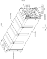
- FIG. 1 is a perspective view schematically showing the configuration of a battery pack according to an embodiment of the present disclosure
- FIG. 2 is an exploded perspective view showing some components of FIG. 1 .
- the battery pack includes a battery module 100, a pack case 200, and a safety bus bar 300.
- the battery module 100 may include at least one battery cell to store and release energy.
- each battery cell may mean a secondary battery.
- one or more battery modules 100 may be included in the battery pack.
- a plurality of battery modules 100 may be included in the battery pack as shown in FIGS. 1 and 2 .
- the plurality of battery modules 100 may be arranged in at least one direction.
- FIGS. 1 and 2 show a form in which eight battery modules 100 are arranged in the X-axis direction.
- FIGS. 3 and 4 An example of a more specific configuration of the battery module 100 is shown in more detail in FIGS. 3 and 4 .
- FIG. 3 is a perspective view showing one battery module 100 included in the battery pack according to an embodiment of the present disclosure. Also, FIG. 4 is a partial perspective view of a form in which some components of FIG. 3 are separated or removed.
- the battery module 100 may include a battery cell 110 (secondary battery).
- the battery cell 110 may include an electrode assembly, an electrolytic solution (electrolyte), and a battery case.
- an electrolytic solution electrolytic solution
- a battery case a pouch-type secondary battery is shown in FIGS. 3 and 4 , other types of secondary batteries, such as cylindrical batteries or prismatic batteries, may be included in the battery module 100.
- the secondary battery may be included in plural.
- a battery assembly may be configured in a form in which a plurality of pouch-type secondary batteries are stacked in an upper and lower direction in a state of being laid down.
- electrode leads 111 of the batteries may be in direct contact with each other or electrically connected through a bus bar or the like.
- the battery module 100 may include a module terminal 140.
- the electrode lead 111 of each battery cell 110 may be located on a front and/or rear side, and the module terminal 140 may be located to be electrically connected to the electrode lead 111.
- the module terminal 140 may be located on the front and/or rear side of the battery module 100 and configured to protrude forward and/or rearward.
- each battery module 100 may include a positive electrode module terminal 140 (+) and a negative electrode module terminal 140 (-) as the module terminals 140.
- the positive electrode module terminal 140 (+) and the negative electrode module terminal 140 (-) may be located on the same side of the battery module 100, for example on the front (-Y-axis direction) side as shown in the drawings.
- the module terminal 140 may allow the secondary battery (battery cell) 110 included in the battery module 100 to be electrically connected to other components outside the battery module 100, such as another battery module 100.
- the pack case 200 may be configured to cover at least a part of the outer side of the battery module 100. Moreover, the pack case 200 may be configured to define an inner space and accommodate one or more battery modules 100 in the inner space. That is, the pack case 200 may be configured to surround at least a part of the outer side of at least one battery module 100.
- the pack case 200 may include a front case 210, a rear case 220, and a left case 230, as shown in FIGS. 1 and 2 , and be configured to cover a front end, a rear end and a left part of the stack of the plurality of battery modules 100.
- the pack case 200 may include a right case, an upper case, and/or a lower case to cover the right side, the upper part, and/or the lower part of the stack of the battery modules 100.
- a pack terminal 201 may be provided on at least one side of the pack case 200.
- the pack terminal 201 may function as a terminal capable of exchanging power with an external charging or discharging device for the battery pack. That is, the pack terminal 201 may be a terminal capable of supplying a charging power to each battery module 100 inside the battery pack or providing a discharging power supplied from each battery module 100 to the outside.
- the pack terminal 201 may include a positive electrode pack terminal 201 (+) and a negative electrode pack terminal 201 (-).
- the positive electrode pack terminal 201 (+) and the negative electrode pack terminal 201 (-) may be located on the same side of the battery pack.
- the positive electrode pack terminal 201 (+) and the negative electrode pack terminal 201 (-) of the battery pack may be located in the left case 230.
- At least a part of the pack case 200 may be made of a material such as steel to protect internal components by securing mechanical strength. Moreover, at least a part of the pack case 200 may serve as a duct.
- the front case 210 may function as a duct.
- a discharge hole may be formed in communication with the duct, as indicated by H1 in FIG. 1 . Accordingly, the venting gas discharged toward the front case 210 may flow along the inner surface of the front case 210 and then be discharged to the outside of the pack case 200 through the discharge hole H1.
- the venting gas is not only high temperature in itself, but also may include high temperature active material particles or flames. Therefore, the front case 210 may be made of a material such as steel to withstand such high-temperature materials easily.
- the pack case 200 may be made of various other materials or shapes. In addition, the pack case 200 may be partially made of different materials.
- the safety bus bar 300 may be included as a component that provides a power path in the battery pack. In addition, one or more safety bus bars 300 may be provided in the battery pack.
- the safety bus bar 300 may be connected between the module terminal 140 provided in the battery module 100 and the pack terminal 201 provided in the pack case 200. Also, the safety bus bar 300 may provide an electrical path through which a charging power or a discharging power may move between the battery module 100 and the pack terminal 201. For example, both ends of the safety bus bar 300 may be connected to the negative electrode module terminal 140 (-) of at least one battery module 100 and the negative electrode pack terminal 201 (-) of the pack case 200, respectively.
- the safety bus bar 300 may be connected between module terminals 140 respectively provided several battery modules 100, so that the battery modules 100 are connected in series and/or in parallel.
- both ends of the safety bus bar 300 may be connected between the positive electrode module terminal 140 (+) of at least one battery module 100 and the negative electrode module terminal 140 (-) of another at least one battery module 100, respectively.
- the safety bus bar 300 may include an electrically conductive material to provide a power path.
- the safety bus bar 300 may be made of a metal material having electrical conductivity.
- the safety bus bar 300 may also have an electrical insulating material so as not to come into contact with other parts.
- the safety bus bar 300 may include a plastic material having electrical insulation and may be configured to cover the outer side of the metal material.
- the safety bus bar 300 may be implemented in the form of a flexible bus bar configured to have flexibility in a form in which a metal plate is wrapped with a polymer material.
- the safety bus bar 300 may be configured to provide a power path, such that the power path is blocked by a venting gas. That is, when a venting gas is generated due to thermal runaway or the like in one or more battery modules 100 included in the battery pack, the safety bus bar 300 may be configured to block the power path by the venting gas. Moreover, when a plurality of safety bus bars 300 are included in the battery pack, all or some of the safety bus bars 300 may be configured to block the power path by the venting gas.
- the safety of the battery pack may be improved.
- a situation in which a venting gas is generated from the battery module 100 may be referred to as an abnormal situation.
- an abnormal situation if the power path of the safety bus bar 300 is blocked, the charging and discharging power connection to the battery pack may be blocked. Therefore, it is possible to block or reduce risk factors that may occur by continuously charging or discharging an abnormal battery pack.
- the battery pack according to the present disclosure may further include a pack bus bar of a general form in addition to the safety bus bar 300.
- the bus bar connecting the battery modules 100 may have a general shape, for example a shape made of one copper plate, rather than the safety bus bar 300.
- the safety bus bar 300 is adopted as a pack bus bar on the negative electrode pack terminal 201 (-)
- a common pack bus bar namely a general pack bus bar made of a copper plate, may be employed on the positive electrode pack terminal 201 (+).
- the safety bus bar 300 may be disposed at a portion where the venting gas is discharged from the battery module 100. This will be described in more detail with reference to FIGS. 5 and 6 along with FIGS. 1 to 4 above.
- FIG. 5 is a cross-sectional view showing the configuration of the battery pack according to an embodiment of the present disclosure, viewed from the top.
- FIG. 6 is an enlarged perspective view showing the portion A1 in FIG. 5 .
- the pack case 200 is not shown.
- the vented gas when a venting gas is generated inside one of the battery modules 100, the vented gas may be discharged in the -Y-axis direction toward the front side, as indicated by an arrow.
- the safety bus bar 300 may be located on the front side of the battery module 100, which is a path through which the venting gas is discharged.
- the battery module 100 may include a module case 120 and a bus bar assembly 130 as shown in FIGS. 3 and 4 .
- the module case 120 may be configured to accommodate at least one secondary battery in the inner space.
- the module case 120 may include an upper plate 121, a lower plate 122, a side plate 123, and a rear plate 124 as shown in the drawing.
- the plurality of plates may be coupled to each other to accommodate the battery assembly in a limited inner space.
- some of the plates included in the module case 120 may be integrated with each other.
- the integrated shape of the lower plate 122 and the side plate 123 may be approximately U-shaped.
- the lower plate 122, the side plate 123 (the left plate, the right plate), and the upper plate 121 may be configured in the form of tubular mono frames integrated with each other.
- the plates of the module case 120 may define an inner space in a coupled state.
- the cell assembly may be accommodated in the inner space.
- the module case 120 may be configured such that at least one side is open.
- the electrode lead 111 of the cell assembly may be positioned in the open portion.
- the battery module 100 may include a bus bar assembly 130 to be coupled to the open portion of the module case 120.
- the bus bar assembly 130 may be coupled to the open portion of the front side of the module case 120.
- the electrode lead 111 of the battery assembly may be located in the front side of the module case 120.
- the bus bar assembly 130 may be coupled with the electrode lead 111.
- the bus bar assembly 130 may include a bus bar housing 131 and a module bus bar 132 as shown in FIGS. 3 and 4 .
- the bus bar housing 131 may be made of an electrically insulating material, such as a plastic material.
- the bus bar housing 131 may be configured such that the module bus bar 132 is seated and fixed thereon.
- the module bus bar 132 may be made of an electrically conductive material, such as a metal material.
- the module bus bar 132 may be connected to at least one electrode lead 111 to electrically connect two or more electrode leads 111 or to transmit sensing information to a control unit such as a battery management system (BMS).
- BMS battery management system
- the battery module 100 included in the battery pack according to the present disclosure as above may be configured so that only a specific part, for example the front side where the bus bar assembly 130 is located, is opened and the other parts may be sealed.
- the venting gas or the like when a venting gas or the like is generated inside the battery module 100, the venting gas or the like may be induced to be discharged only to the open portion of the module case 120, for example a front side where the bus bar assembly 130 is located.
- a slit may be formed in the bus bar assembly 130 so that the electrode lead 111 may pass therethrough.
- gas, sparks, flames, or the like inside the module may be discharged to the outside of the module case 120 through the slit of the bus bar assembly 130, as indicated by arrows in FIGS. 5 and 6 .
- the safety bus bar 300 may be located in the portion where the venting gas is discharged from the battery module 100 as above. Therefore, in the battery pack according to the present disclosure, it may be regarded that each battery module 100 is configured to induce the venting gas generated inside toward the safety bus bar 300 by means of the configuration of the module case 120 and the bus bar assembly 130. That is, it may be regarded that the safety bus bar 300 is located in the open portion so that the venting gas may be discharged from the battery module 100. In addition, when the venting gas is induced toward the safety bus bar 300 and discharged as above, the power path of the safety bus bar 300 may be blocked by the temperature and/or pressure of the venting gas.
- the safety bus bar 300 may be configured such that at least a portion thereof is cut by the venting gas. This will be described in more detail with reference to FIG. 7 .
- FIG. 7 is a diagram schematically showing the configuration in which a safety bus bar 300 is cut by a venting gas in the configuration of FIG. 6 .
- the high-temperature venting gas may be discharged with high pressure to the safety bus bar 300 located in front of the bus bar assembly 130.
- the corresponding portion of the safety bus bar 300 may be removed and cut.
- a predetermined portion the safety bus bar 300 may be removed in the form of crumbling due to the discharge of the venting gas.
- the power path blocking effect may be stably secured by cutting the safety bus bar 300. Moreover, in this case, even a predetermined portion of the safety bus bar 300, particularly a portion having electrical conductivity, may be completely removed into the form of fine particles. Therefore, a problem in which the cut safety bus bar 300 contacts the pack case 200, which is a conductor, or an electrode terminal of a different polarity to cause a short circuit may be prevented.
- the safety bus bar 300 may be configured such that at least a part is fixed to the battery module 100 or the pack case 200.
- the safety bus bar 300 may be configured to be fixed to module cases 120 or bus bar assemblies 130 of several battery modules 100. In this case, the position of the safety bus bar 300 may be fixed despite the ejection pressure of the venting gas, and the partial removal process by the venting gas may be performed more smoothly.
- the battery module 100 may be configured such that only the front side is opened, but the rear side may also be configured in an open form along with the front side.
- the bus bar assembly 130 may be included instead of the rear plate 124.
- the rear case 220 of the pack case 200 may function as a duct like the front case 210.
- FIG. 8 is a diagram schematically showing the configuration of a front end of the battery pack according to an embodiment of the present disclosure.
- the battery pack may include a plurality of battery modules 100.
- the plurality of battery modules 100 may be stacked in at least one direction.
- the battery pack may include eight battery modules 100 arranged side by side in a horizontal direction, particularly in a left and right direction (X-axis direction).
- the safety bus bar 300 may be configured to be elongated long along the stacking direction of the battery module 100. That is, when the battery modules 100 are arranged side by side in a horizontal direction, the safety bus bar 300 may be configured to be elongated in a horizontal direction. For example, as shown in FIG. 8 and the like, the safety bus bar 300 may be configured to be elongated along the left and right direction (X-axis direction), which is the stacking direction of the battery module 100.
- the safety bus bar 300 may be connected between the pack terminal 201 and the module terminal 140 to provide a power path. At this time, the module terminal 140 of the battery module 100 located farthest from the pack terminal 201 on one side of the pack case 200 needs to be connected with the pack terminal 201.
- the safety bus bar 300 according to the present disclosure may be employed.
- the pack terminal 201 may be located at the left end of the battery pack.
- one of the module terminals 140 of the battery module 100 stacked on the rightmost side of the battery pack needs to be connected to the pack terminal 201.
- the safety bus bar 300 may be configured to be elongated in the left and right direction to connect the pack terminal 201 located on the left side of the battery pack and the module terminal 140 of the battery module 100 located on the right side.
- the safety bus bar 300 may be provided to connect the negative electrode pack terminal 201 (-) located on the left side and the negative electrode module terminal 140 (-) of the battery module 100 located on the rightmost side.
- each of the plurality of battery modules 100 disposed side by side in the left and right direction may be configured to discharge the venting gas forward or backward.
- each of the eight battery modules 100 may be opened at the front side where the bus bar assembly 130 is located, as described above in FIGS. 3 to 6 , so that the venting gas may be discharged through the front portion (-Y-axis direction).
- the safety bus bar 300 may be disposed on the front or rear side of the stack of the plurality of battery modules 100.
- one safety bus bar 300 may be disposed on the front or rear side with respect to all eight battery modules 100.
- the safety bus bar 300 may be configured to be elongated in the left and right direction, so as to be disposed on the front side of eight battery modules 100. That is, the safety bus bar 300 may be disposed on the outer side of the open portion through which the venting gas is discharged from the battery module 100.
- the safety bus bar 300 may be disposed on the outer side of the bus bar assembly 130, for example on the front side of the slit of the bus bar assembly 130.
- the safety bus bar 300 may be cut by the venting gas. Therefore, in this case, with one safety bus bar 300, a configuration for securing safety during venting of the plurality of battery modules 100 may be effectively achieved.
- FIG. 9 is a cross-sectional view schematically showing the configuration of the safety bus bar 300 according to an embodiment of the present disclosure, viewed from the top.
- FIG. 9 may be regarded as a cross-sectional configuration along the line A3-A3' of FIG. 7 .
- the safety bus bar 300 may be configured to include two or more different types of metal.
- the safety bus bar 300 may include two or more metals having different melting points.
- the safety bus bar 300 may include two or more metals having different electrical conductivities.
- the safety bus bar 300 may include a first metal, such as the portion indicated by M1 in FIG. 9 , and a second metal, such as the portion indicated by M2.
- the second metal may be a metal having a lower melting point and electrical conductivity than the first metal.
- the safety bus bar 300 may include copper and aluminum.
- the power transmission function of the safety bus bar 300 itself may be maintained at a certain level or above through the metal having a high melting point and electrical conductivity, such as copper.
- the metal when heat is applied by the venting gas to the metal having a low melting point and low electrical conductivity in the safety bus bar 300, the metal is melted to be separated or removed from the safety bus bar 300, so that the safety bus bar 300 is cut to stably achieve the power path blocking function and the short circuit prevention function. Therefore, in this case, the power transmission function in a normal state and the power blocking function and the short circuit prevention function in an emergency may be stably performed by the safety bus bar 300.
- the safety bus bar 300 may be configured such that two or more different types of metal are joined to each other.
- the safety bus bar 300 may be configured such that two or more types of metal plates are joined to each other in a state of being in surface contact with each other.
- the safety bus bar 300 is configured in the form of a clad metal having two or more types of metal.
- the safety bus bar 300 may be configured in a form in which the first metal plate and the second metal plate are joined to each other.
- the first metal plate may be a metal plate made of copper, namely a copper plate
- the second metal plate may be a metal plate made of aluminum, namely an aluminum plate.
- the safety bus bar 300 may be regarded as having a clad metal made of copper and aluminum.
- all of the power transmission function, the power blocking function, and the short circuit prevention function may be easily performed through two or more metal plates of different types, particularly different melting points.
- the safety bus bar 300 when the safety bus bar 300 includes two or more different types of metal, at least one of these metals may be configured to be meltable by the venting gas.
- at least one type of metal included in the safety bus bar 300 may be made of a material having a lower melting point than the temperature of the venting gas.
- a venting gas is generated from the battery module 100 included in the battery pack, if the temperature of the venting gas is approximately 950°C, a metal material having a lower melting point than this may be used as the second metal plate.
- the second metal plate may be made of an aluminum material having a melting point of about 660°C.
- the second metal plate when a gas is vented from the battery module 100, the second metal plate may be easily melted by the venting gas. Moreover, the molten material of the second metal plate may be released from the safety bus bar 300 by the pressure of the venting gas.
- the first metal plate may be made of a material having a higher melting point than that of the second metal plate.
- the first metal plate may be made of a copper material having a melting point of about 1084°C. Even if the melting point of the first metal plate made of copper is slightly higher than the temperature of the venting gas, the thickness may not be thick due to the presence of the second metal plate. Therefore, the first metal plate may also be removed in a crumbling form by the venting gas.
- the metal layer with a low melting point may be formed thicker than the metal layer with a high melting point.
- the metal layer with a high melting point may be formed thinner than the metal layer with a low melting point.
- the safety bus bar 300 may be designed such that T1 and T2 have the following relationship. T 1 ⁇ T 2 .
- the first metal plate may be formed of two layers, namely an inner metal plate M1 1 and an outer metal plate M12.
- the thickness T1 of the first metal plate M1 may be a value obtained by adding the thickness T11 of the inner metal plate M11 and the thickness T12 of the outer metal plate M12.
- the second metal plate M2 may have a thickness greater than the sum of the thicknesses of the inner metal plate M11 and the outer metal plate M12.
- the thickness of the second metal plate may be 2 times or more, 3 to 4 times or more, or 7 to 8 times or more than the thickness of the first metal plate.
- the thickness T1 of the copper plate may be 0.05 mm and the thickness T2 of the aluminum plate may be 0.45 mm.
- the power transmission and blocking function, the short circuit prevention functions, and the like by the safety bus bar 300 may be secured more stably. That is, according to this embodiment, even if the first metal plate with a high melting point and good electrical conductivity is included in the safety bus bar 300 to improve the power transmission function, it may be regarded that the second metal plate with a low melting point is included in a relatively large amount. Therefore, in case of an emergency, the power blocking function and the short circuit prevention functions of the safety bus bar 300 may be more effectively achieved by the venting gas.
- the safety bus bar 300 may further include an insulation layer P.
- the insulation layer P is made of a material having electrical insulation, for example a plastic material, and may be located on the outer side of the safety bus bar 300.
- the insulation layer P may be configured to surround the first metal layer M1 and the second metal layer M2. Therefore, in the case of the cross-sectional configuration shown in FIG. 9 , it may be regarded that the safety bus bar 300 includes the inner insulation layer P, the first metal layer M1 (inner metal plate), the second metal layer M2, the first metal layer M1 (outer metal plate), and the outer insulation layer P.
- the insulation layer P may be melted by the venting gas, and according to this embodiment of the present disclosure, since the metal layer included inside may be melted or crumbled and removed by the venting gas, the short-circuit prevention function by the safety bus bar 300 may be secured more stably.
- the metal layer having a high melting point may be formed with a plurality of layers.
- the first metal plate (first metal layer M1) having a relatively high melting point, such as a copper plate may be formed with a plurality of layers. That is, in the embodiment of FIG. 9 , the first metal plate is a copper plate and may be regarded as having an inner copper plate and an outer copper plate.
- the plurality of first metal plates may be disposed on both sides of the second metal plate having a low melting point.
- the safety bus bar 300 may be configured to have metal layers, including one aluminum layer and two copper layers located on both surfaces thereof.
- the thickness of the first metal plate may be made thinner. That is, in order to secure the electrical conductivity of the safety bus bar 300 to a certain level or above, if the thickness of the first metal plate needs to be a certain level or above, the first metal plate may be configured with multiple layers so that the thickness of each layer becomes thinner. For example, in order to secure the electrical conductivity of the safety bus bar 300, if the thickness of the first metal plate needs to be 0.05 mm or more, the thickness of 0.05 mm may be divided into two or more so that the thickness of each first metal plate becomes thinner. For example, when the first metal plate includes an inner metal plate and an outer metal plate, each of the inner metal plate and the outer metal plate may have a thickness of 0.025 mm.
- the electrical conductivity of the safety bus bar 300 may be stably maintained by securing the entire thickness of the first metal plate M1 to a certain level or above.
- the thickness of each of the first metal plate M 1 becomes thin, the effect of crumbling into powder or the like by the venting gas may be easily achieved.
- the melting point of copper may be higher than the temperature of the venting gas, but as the thickness thereof becomes thinner, the effect of crumpling by the venting gas may be more easily achieved.
- the inner metal plate M1 when the first metal plate M1 includes an inner metal plate and an outer metal plate, the inner metal plate may have the same thickness as the outer metal plate. In this case, by making the thicknesses of the inner metal plate and the outer metal plate as thin as possible, the effect of crumpling the first metal plate may be achieved more easily.
- the thickness of the inner metal plate may be formed thinner than the thickness of the outer metal plate.
- the venting gas may collides with the inner metal plate first. At this time, when the thickness of the inner metal plate is thin, the inner metal plate may be more easily removed and the second metal plate may be melted more quickly.
- the safety bus bar 300 may be cut off by the venting gas discharged from the battery module 100, so that power blocking and short circuit prevention functions may be implemented.
- other components of the battery pack such as the battery module 100, may be configured to more easily implement the configuration of cutting the safety bus bar 300 by the venting gas. Embodiments related to this will be described in more detail with reference to FIG. 10 .
- FIG. 10 is a cross-sectional view schematically showing some components of the battery pack according to an embodiment of the present disclosure.
- the bus bar housing 131 of the bus bar assembly 130 and the safety bus bar 300 are shown excluding other components.
- slits S1 to S6 penetrating from the inner side to the outer side of the battery module 100 may be formed in the bus bar housing 131.
- the left side is the inner portion of the battery module 100
- the right side is the outer portion of the battery module 100.
- the electrode leads 111 of the secondary battery may be inserted into this slit S1 to S6 and connected to the module bus bar 132 at the outer side.
- the venting gas may be discharged to the outside through the slits S1 to S6, as indicated by arrows.
- the slits S1 to S6 of the bus bar assembly 130 may be configured such that the venting gas passing therethrough is directed toward the safety bus bar 300.
- the safety bus bar 300 may be located on the front side (outer side) of the bus bar assembly 130.
- at least some of the slits S1 to S6 of the bus bar assembly 130 may be configured in an inclined shape so that venting gas flows toward the safety bus bar 300.
- the safety bus bar 300 is located on the front side of the bus bar assembly 130, but may be located in a central portion in the upper and lower direction (Z-axis direction). At this time, at least some of the slits S1 to S6 of the bus bar assembly 130 may be configured in an inclined shape toward the front center portion. That is, like S 1 and S2, the slit located higher than the safety bus bar 300 in the vertical direction (Z-axis direction) in the bus bar assembly 130 may be configured to be inclined downward from the inner side to the outer side. In addition, like S5 and S6, the slit located lower than the safety bus bar 300 in the vertical direction (Z-axis direction) in the bus bar assembly 130 may be configured to be inclined upward from the inner side to the outer side.
- the slit located in the center portion in the upper and lower direction in the bus bar assembly 130 is located similar to the safety bus bar 300 in the vertical direction (Z-axis direction), so it may be configured to discharge the in the horizontal direction (direction parallel to the ground).
- the venting gas passing through the slit of the bus bar assembly 130 may be concentrated on the safety bus bar 300. Therefore, the effect of cutting and removing the safety bus bar 300 may be further improved.
- the slits of the bus bar assembly 130 are configured in an inclined shape, at least some of the slits may have different inclination angles.
- the inclination angle may mean an angle inclined from the horizontal direction (Y-axis direction).
- the slits inclined downward may be configured to have different inclination angles.
- S 1 and S2 which are slits located higher than the safety bus bar 300, are inclined downward, but their slopes may be different from each other.
- the slit S 1 located at the relatively upper side may have a greater inclination angle in the lower direction than that of the slit S2 located at the relatively lower side. That is, as the slit is located higher than the safety bus bar 300 in the upper and lower direction, its inclination angle may be formed to be larger in the lower direction.
- the slits inclined upward may be configured to have different inclination angles.
- S5 and S6, which are slits located lower than the safety bus bar 300 are inclined upward, but their slopes may be different from each other.
- the slit S6 located at the relatively lower side may have a greater inclination angle in the upper direction than that of the slit S5 located at the relatively upper side. That is, as the slit is located lower than the safety bus bar 300 in the upper and lower direction, its inclination angle may be formed to be larger in the upper direction.
- a slit farther apart in the upper and lower direction from the safety bus bar 300 may be configured to have a relatively large inclination angle.
- the effect of concentrating the venting gas passing through the slit to the safety bus bar 300 may be further increased. Therefore, in this case, the effect of cutting and removing the safety bus bar 300 by the venting gas may be enhanced further.
- FIG. 11 is a perspective view schematically showing some components of a safety bus bar 300 according to another embodiment of the present disclosure.
- FIG. 11 may be regarded as showing the inner surface of the safety bus bar 300, namely the surface viewed from the battery module 100. This embodiment will be mainly explained based on features different from the former embodiments.
- the safety bus bar 300 may have a groove formed as indicated by G.
- the groove G may be formed concavely on the surface of the safety bus bar 300 in an inner direction thereof.
- the groove G may be formed in a concave shape in the outer direction of the battery pack on the inner surface of the safety bus bar 300.
- the groove G may be formed such that the thickness of the safety bus bar 300 becomes thinner.
- the safety bus bar 300 may be cut by the venting gas more effectively.
- the venting gas may cut the safety bus bar 300 more easily by the groove G.
- the cutting position of the safety bus bar 300 by the venting gas may be guided by the groove G.
- two grooves G may be formed on both sides of the portion of the safety bus bar 300 facing the venting gas.
- the venting gas is ejected into the portion between the two grooves G, and the portion between the two grooves G may be lost by the venting gas. Therefore, in this case, the safety bus bar 300 is cut more reliably, and also the cutting position may be clearly defined.
- FIG. 12 is a perspective view schematically showing some components of a safety bus bar according to still another embodiment of the present disclosure.
- FIG. 12 may also be regarded as showing the inner surface of the safety bus bar 300.
- the groove G may be formed on the inner surface of the safety bus bar 300 to directly face the venting gas ejection portion. That is, as indicated by an arrow in FIG. 12 , when a venting gas is ejected from the battery module 100, the groove G of the safety bus bar 300 may be formed at a portion that faces the venting gas. At this time, the groove G may be formed with a wider area than the groove G formed in the embodiment of FIG. 11 .
- the force of cutting the safety bus bar 300 by the venting gas may be improved even with one groove G.
- the safety bus bar 300 and the battery pack may be manufactured more efficiently.
- FIG. 13 is a perspective view schematically showing some components of a safety bus bar 300 according to still another embodiment of the present disclosure.
- FIG. 13 may be regarded as a cross-sectional view showing the configuration of the safety bus bar 300, viewed from the top.
- FIG. 13 may be regarded as a modification of the embodiment of FIG. 12 .
- a groove G may be formed on the inner surface of the safety bus bar 300at a portion facing the venting gas.
- the groove G of the safety bus bar 300 may have an inclined surface that is inclined in a specific direction, as indicated by GS.
- the inclined surface GS may be formed such that the thickness of the safety bus bar 300 becomes thinner toward the center portion GC of the groove G. That is, the groove G of the safety bus bar 300 may be configured such that its depth increases toward the center portion GC from both ends.
- the venting gas when a venting gas is ejected into the groove G of the safety bus bar 300, the venting gas may be concentrated on a specific part of the groove G.
- the venting gas moves to the center portion GC along the inclined surface GS of the groove G, so that the heat and pressure of the venting gas may be more concentrated on the center portion GC of the groove G. Therefore, the safety bus bar 300 may be cut more quickly and reliably. Therefore, the effect of cutting the safety bus bar 300 by the venting gas may be further improved.
- the battery pack according to the present disclosure may further include various other components of the battery pack known at the time of filing of this application.
- the battery pack according to the present disclosure may further include components such as a battery management system (BMS), a current sensor, and a fuse.
- BMS battery management system
- a current sensor current sensor
- a fuse fuse
- An energy storage system may include at least one battery pack according to the present disclosure.
- a plurality of battery packs according to the present disclosure may be included in the energy storage system to have a large energy capacity.
- the energy storage system according to the present disclosure may further include various other components of the energy storage system known at the time of filing of this application.
- the energy storage system may be used in various places or devices, such as a smart grid system or an electric charging station.
- the vehicle according to the present disclosure may include the battery pack according to the present disclosure.
- the vehicle according to the present disclosure may further include other various components included in a vehicle, in addition to the battery pack.
- the vehicle according to the present disclosure may further include a vehicle body, a motor, and a control device such as an electronic control unit (ECU), in addition to the battery pack according to the present disclosure.
- ECU electronice control unit
Landscapes
- Chemical & Material Sciences (AREA)
- Chemical Kinetics & Catalysis (AREA)
- Electrochemistry (AREA)
- General Chemical & Material Sciences (AREA)
- Inorganic Chemistry (AREA)
- Engineering & Computer Science (AREA)
- Aviation & Aerospace Engineering (AREA)
- Connection Of Batteries Or Terminals (AREA)
- Battery Mounting, Suspending (AREA)
- Sealing Battery Cases Or Jackets (AREA)
Applications Claiming Priority (3)
| Application Number | Priority Date | Filing Date | Title |
|---|---|---|---|
| KR20210113529 | 2021-08-26 | ||
| KR1020220106420A KR20230031159A (ko) | 2021-08-26 | 2022-08-24 | 안전성이 향상된 배터리 팩 |
| PCT/KR2022/012768 WO2023027535A1 (fr) | 2021-08-26 | 2022-08-25 | Bloc-batterie à sécurité améliorée |
Publications (1)
| Publication Number | Publication Date |
|---|---|
| EP4235949A1 true EP4235949A1 (fr) | 2023-08-30 |
Family
ID=85321926
Family Applications (1)
| Application Number | Title | Priority Date | Filing Date |
|---|---|---|---|
| EP22861743.7A Pending EP4235949A1 (fr) | 2021-08-26 | 2022-08-25 | Bloc-batterie à sécurité améliorée |
Country Status (5)
| Country | Link |
|---|---|
| US (1) | US20240047840A1 (fr) |
| EP (1) | EP4235949A1 (fr) |
| JP (1) | JP2023548128A (fr) |
| AU (1) | AU2022332328A1 (fr) |
| WO (1) | WO2023027535A1 (fr) |
Family Cites Families (7)
| Publication number | Priority date | Publication date | Assignee | Title |
|---|---|---|---|---|
| CN103650209B (zh) * | 2012-01-03 | 2016-08-17 | 株式会社Lg化学 | 电池组和应用于该电池组的连接条 |
| KR20150121518A (ko) * | 2014-04-21 | 2015-10-29 | 에스케이배터리시스템즈 주식회사 | 단락시 안전성 확보가 가능한 배터리모듈 및 배터리팩 |
| CN207765491U (zh) * | 2017-11-29 | 2018-08-24 | 长城汽车股份有限公司 | 电池包和具有其的车辆 |
| JP2020042968A (ja) * | 2018-09-10 | 2020-03-19 | 株式会社豊田自動織機 | 蓄電装置モジュール |
| CN111668527A (zh) * | 2019-03-07 | 2020-09-15 | 宁德时代新能源科技股份有限公司 | 一种电池模块及电池包 |
| KR20210113529A (ko) | 2020-03-06 | 2021-09-16 | 삼성디스플레이 주식회사 | 표시 기판 및 이를 포함하는 표시 장치 |
| KR20220106420A (ko) | 2021-01-22 | 2022-07-29 | 김학재 | 휴대용 약액 도포구 |
-
2022
- 2022-08-25 EP EP22861743.7A patent/EP4235949A1/fr active Pending
- 2022-08-25 US US18/269,236 patent/US20240047840A1/en active Pending
- 2022-08-25 JP JP2023526117A patent/JP2023548128A/ja active Pending
- 2022-08-25 AU AU2022332328A patent/AU2022332328A1/en active Pending
- 2022-08-25 WO PCT/KR2022/012768 patent/WO2023027535A1/fr active Application Filing
Also Published As
| Publication number | Publication date |
|---|---|
| AU2022332328A1 (en) | 2023-06-15 |
| US20240047840A1 (en) | 2024-02-08 |
| JP2023548128A (ja) | 2023-11-15 |
| WO2023027535A1 (fr) | 2023-03-02 |
Similar Documents
| Publication | Publication Date | Title |
|---|---|---|
| CN110915025B (zh) | 汇流条、包括其的电池模块和包括该电池模块的电池组 | |
| US11673205B2 (en) | Battery module having bus bar, and battery pack | |
| US10892468B2 (en) | Battery module with short-circuit unit, and battery pack and vehicle including the same | |
| EP4068480A1 (fr) | Bloc-batterie, véhicule et dispositif électronique le comprenant | |
| EP3561906B1 (fr) | Module de batterie | |
| EP3512008A1 (fr) | Module de batterie et bloc-batterie, et véhicule les comprenant | |
| EP3293782B1 (fr) | Module de batterie et bloc-batterie le comprenant | |
| CN113826270B (zh) | 电池组、电子装置及车辆 | |
| EP3989354A1 (fr) | Module de batterie comprenant une plaque de barre omnibus, bloc-batterie comprenant un module de batterie, et dispositif électronique | |
| CN108155429A (zh) | 过充安全保护装置 | |
| EP4053989A1 (fr) | Module de batterie comportant une barre omnibus, bloc-batterie et véhicule | |
| EP4053990A1 (fr) | Module de batterie comprenant un module de barre omnibus, bloc-batterie le comprenant et dispositif électronique | |
| US9843032B2 (en) | Battery module | |
| KR20190001408A (ko) | 배터리 모듈과 이를 포함하는 배터리 팩 및 자동차 | |
| EP4235949A1 (fr) | Bloc-batterie à sécurité améliorée | |
| EP4167363A1 (fr) | Module de batterie, bloc-batterie, et véhicule comprenant ceux-ci | |
| KR20230031159A (ko) | 안전성이 향상된 배터리 팩 | |
| CN116670923A (zh) | 具有提高的安全性的电池组 | |
| KR102267056B1 (ko) | 배터리 모듈과 이를 포함하는 배터리 팩 및 자동차 | |
| EP4329062A1 (fr) | Module de batterie qui peut supprimer l'émission de gaz ou de flammes à travers le connecteur en cas de combustion interne | |
| EP4354597A1 (fr) | Bloc-batterie, et système de stockage d'énergie et véhicule comprenant un bloc-batterie | |
| JP7367021B2 (ja) | コネクター、バッテリー管理ユニット及びバッテリーパック | |
| EP3358644B1 (fr) | Cellule de batterie et module de batterie | |
| KR102603907B1 (ko) | 이차 전지 모듈 케이스 및 이를 포함하는 이차 전지 모듈 | |
| CN117223162A (zh) | 电池组以及包括电池组的能量存储系统和车辆 |
Legal Events
| Date | Code | Title | Description |
|---|---|---|---|
| STAA | Information on the status of an ep patent application or granted ep patent |
Free format text: STATUS: THE INTERNATIONAL PUBLICATION HAS BEEN MADE |
|
| PUAI | Public reference made under article 153(3) epc to a published international application that has entered the european phase |
Free format text: ORIGINAL CODE: 0009012 |
|
| STAA | Information on the status of an ep patent application or granted ep patent |
Free format text: STATUS: REQUEST FOR EXAMINATION WAS MADE |
|
| 17P | Request for examination filed |
Effective date: 20230525 |
|
| AK | Designated contracting states |
Kind code of ref document: A1 Designated state(s): AL AT BE BG CH CY CZ DE DK EE ES FI FR GB GR HR HU IE IS IT LI LT LU LV MC MK MT NL NO PL PT RO RS SE SI SK SM TR |